Embed Size (px)
Citation preview

8/17/2019 InTech-Hexa Band Multi Standard Planar Antenna Design for Wireless Mobile Terminal
http://slidepdf.com/reader/full/intech-hexa-band-multi-standard-planar-antenna-design-for-wireless-mobile-terminal 1/17
1
Hexa-Band Multi-Standard Planar AntennaDesign for Wireless Mobile Terminal
Yu-Jen Chi1 and Chien-Wen Chiu2 1Department of Electrical Engineering, National Chiao Tung University,
2Department of Electric Engineering, National Ilan University,Taiwan
1. IntroductionElectronic devices such as mobile phones and laptop computers are parts of modern life.Users of portable wireless devices always desire such devices to be of small volume, lightweight, and low cost. Thanks to the rapid advances in very large scale integration (VLSI)technology, this dream has become a reality in the past two decades. As technology growsrapidly, a mobile is not just a phone recently. The highly integration of circuits makes themobile phone and the PDA (personal digital assistant) been combined into a single handset,which is called a smart phone. Also, the Internet carries various information resources andservices, such as electronic mail, online chat, file transfer and file sharing, these attractiveproprieties make wireless internet service becomes an important function that should beintegrated into mobile devices. There are many ways for the user to connect to the internet.The traditional wireless local area network (WLAN) is a popular communication system foraccessing the Internet. However, the reach of WiFi is very limited. WLAN connectivity isprimarily constrained to hotspots, users need to find the access points and can only use it incertain rooms or areas. As the user get out of range of the hotspot, the signal will becomevery weak and the user may lose the connection. This disadvantage limits the mobility ofwireless communication. Except for the widely used wireless local area network, thirdgeneration (3G) mobile telephony based on the High Speed Downlink Packet Access(HSDPA), which is part of the UMTS standards in 3G communications protocol, is anotherhigh speed wireless internet access service. It has become popular nowadays that people canget to the internet via cellular communication system. This technology gives the users the
ability to access to the Internet wherever the signal is available from the cellular base station.However, the quality sometimes depends on the number of users simultaneously connectedper cellular site. In addition to utilizing WLAN/3G dual-mode terminals to enhanceefficiency of mobile number portability service, WiMAX (the Worldwide Interoperability forMicrowave Access) is an emerging telecommunications technology that provides wirelessdata transmission in a variety of ways, ranging from point-to-point links to full mobilecellular-type access. WiMAX is similar to Wi-Fi but it can also permit usage at much greaterdistances. The bandwidth and range of WiMAX make it suitable for the applications likeVoIP (Voice over Internet Protocol) or IPTV (Internet Protocol Television). Many peopleexpect WiMAX to emerge as another technology that may be adopted for handset devices inthe near future.
www.intechopen.com

8/17/2019 InTech-Hexa Band Multi Standard Planar Antenna Design for Wireless Mobile Terminal
http://slidepdf.com/reader/full/intech-hexa-band-multi-standard-planar-antenna-design-for-wireless-mobile-terminal 2/17
Advanced Transmission Techniques in WiMAX4
The rapid progress in mobile communication requires that many functions and wirelesscommunication systems be integrated into a mobile phone. When portability is taken intoaccount, antenna that can be built in the phone device is desirable. This has led to a greatdemand for designing multiband antennas for handset devices. Among existing built-in or
internal type scheme, the inverted-F (IFA) or planar inverted-F antenna (PIFA) are the mostpromising candidates. The linear inverted-F antenna, which is the original version of thePIFA, has been described by R. King in 1960 as a shunt-driven inverted-L antenna-transmission line with open-end (king et al., 1960). The PIFA, which is constructed byreplacing the linear radiator element of IFA with a planar radiator element, can also beevolved from a microstrip antenna. Taga first investigated PIFA’s performance for 800MHzband portable unit radio in 1987 (Taga & Tsunekawa, 1987). He also wrote a chapter in his
textbook to teach how to design a single band PIFA (Hirasawa & Haneishi, 1922). The PIFAor IFA are not only small in size but also have a broadband bandwidth. Since it is cheap andeasy to fabricate, it has become very popular with mobile phone manufacturers. Many
references concerning PIFA and its relatives were published in the decade.In the past decade, researches for variation of the PIFA and multiband antenna grow rapidlylike mushroom. Tri-band, quad-band, penta-band or hexa-band antenna can be found inmany journals (Chiu & Lin, 2002; Guo et al., 2003, 2004; Ciais et al., 2004; Chen, 2007;Bancroft, 2005; Ali & Hayes, 2000; Soras et al., 2002; Nepa et al., 2005; Wong et al., 2005; Liu& Gaucher, 2004, 2007; Wang et al., 2007). For example, Chiu presented a tri-band PIFA forGSM800/DCS1800/PCS1900 in 2002 (Chiu & Lin, 2002) . Using two folded arms betweenthe two plates, Guo at el. proposed a compact internal quad-band for coveringGSM900/DCS1800/PCS1900 and ISM2450 bands (Guo, et al., 2003). By adding threequarter-wavelength parasitic elements to create new resonances, Ciais et al. presented adesign of a compact quad-band PIFA for mobile phones (Ciais et al., 2004). In 2004, Guo &Tan proposed a new compact six-band but complicated internal antenna. His antenna iscomprised of a main plate, a ground plane, a parasitic plate and a folded stub perpendicularto the two main plates (Guo & Tan, 2004).
In order to integrate all the wireless services into a mobile terminal and have an effectiveusage of the precious board space in the mobile device, multiband antenna that is designedto operate on several bands is necessary. However, designing a multiband antenna in anarrow space is a great challenge; a method that decrease the complexity of the antennastructure is also necessary to be investigated. Guo et. al. have recently designed quad-bandantennas for mobile phones (Chiu & Lin, 2002; Nashaat et al., 2005; Karkkainen, 2005) anddual-band antennas for WLAN operations (Su & Chou, 2008). However, few of theseantennas simultaneously cover the following communication standards: GSM (880-960MHz), DCS (1710-1880 MHz), PCS (1850-1990 MHz), UMTS2100 (1920-2170 MHz), WLAN +Bluetooth (2400-2480 MHz), WiMAX (2500-2690 MHz), HiperLAN/2 in Europe (5150-5350 /5470-5725 MHz) and IEEE 802.11a in the U.S. (5150-5350 / 5725-5825 MHz) (Liu & Gaucher,2004, 2007; Wang et al., 2007; Rao & Geyi, 2009; Nguyen et al., 2009; Anguera et al., 2010;Kumar et al., 2010; Liu et al., 2010; Hsieh et al., 2009; Yu & Tarng, 2009; Hong et at., 2008;Guo et al., 2004; Li et al., 2010). This chapter proposes a planar multiband antenna thatcomprises a dual-band inverted-F resonator and two parasitic elements to cover all the
communication standards mentioned above. One element is devoted to generating a dipolemode and another is helpful to excite a loop mode so as to broaden the impedance
www.intechopen.com

8/17/2019 InTech-Hexa Band Multi Standard Planar Antenna Design for Wireless Mobile Terminal
http://slidepdf.com/reader/full/intech-hexa-band-multi-standard-planar-antenna-design-for-wireless-mobile-terminal 3/17
Hexa-Band Multi-Standard Planar Antenna Design for Wireless Mobile Terminal 5
bandwidth. This hepta-band antenna is designed for a mobile device and the parasiticelement broadens the impedance bandwidth to about 45.5%. This antenna is extended tosimultaneously operate in WLAN, WiMAX, and WWAN systems. It covers all cellularbands world-wide and all wireless network bands, such as the following communication
standards: GSM/DCS/PCS/UMTS/WLAN/WiMAX/HIPERLAN2/IEEE 802.11. Theantenna structure that measures only 50 mm x 12 mm x 0.5 mm can be easily fabricated bystamping from a metal plate. The following describes the details of the proposed antenna aswell as the experimental results.
Parasitic Element 1
Parasitic
Element 2
Dual Band Main
Resonator Ground Plane
Feeding Point
Shorting Strip
1 0 0 m m
5 0 m m
L
x
yz
(a)
(b)
Fig. 1. The proposed antenna (a) Three-dimensional configuration of the proposed antenna(b) Plane view of the antenna structure.
www.intechopen.com

8/17/2019 InTech-Hexa Band Multi Standard Planar Antenna Design for Wireless Mobile Terminal
http://slidepdf.com/reader/full/intech-hexa-band-multi-standard-planar-antenna-design-for-wireless-mobile-terminal 4/17
Advanced Transmission Techniques in WiMAX6
2 Antenna design
2.1 Design of a dual-band antenna
Modern mobile terminals require small and thin design, therefore, planar inverted-F
antenna, which requires a spacing of about 7 mm ~ 12 mm between the antenna and thesubstrate to achieve the sufficient operating bandwidth, is not suitable to be integrated with
the present thin mobile terminals although it is popular and widely used. Fig. 1(a) shows a
three dimensional view of the proposed design. The antenna, which is mounted on the top
edge of the printed circuit board (PCB), is fed by a 50 Ω coaxial cable. The antenna is
coplanar with the system ground of the PCB. The dielectric constant of the PCB used here is
4.4 and the thickness is 1.58 mm. As shown in Fig. 1(b), this radiating structure measures 50
mm × 12 mm × 1.5 mm and can be extended to a single metallic plate. It is basically an
inverted-F antenna in which the quarter-wavelength characteristic is obtained thanks to a
short-circuited metallic strip. As indicated in Fig. 1(b), this design comprises a direct-feed
dual band main resonator with two branches (A) and (B), and two parasitic elements (C)and (D) excited by electromagnetic coupling, to achieve multiband operation.
Shown in Fig. 2 is a typical configuration of an inverted-F antenna. It can be fed by a mini-
coaxial cable which is connected to the RF module. Here, H is the height of the radiator
above the ground plane, LF is the horizontal length from the feed point to the open end of
the antenna, and LB is the horizontal length from the feed point to the closed end of the
antenna. This antenna is a quarter-wavelength radiator with one short end and one open
end. The resonant frequency can be easily calculated by the formula:
4( )B F
c f
H L L
the where c is the speed of light. The resonant frequency can be adjusted by changing the
value LF, and the distance LB between the feed point and shorting strip can be used to adjust
the input impedance. The height H of the antenna is closely related to the impedance
bandwidth where the Q factor can be reduced by increasing the antenna height to broaden
the bandwidth and vice versa. Variations of IFA Antenna height cause some effects on
bandwidth. Fig. 3 shows the simulation results with different antenna height H. It is found
that increasing the height will increase the impedance bandwidth.
Fig. 2. A typical inverted-F Antenna.
www.intechopen.com

8/17/2019 InTech-Hexa Band Multi Standard Planar Antenna Design for Wireless Mobile Terminal
http://slidepdf.com/reader/full/intech-hexa-band-multi-standard-planar-antenna-design-for-wireless-mobile-terminal 5/17
Hexa-Band Multi-Standard Planar Antenna Design for Wireless Mobile Terminal 7
0.5 1 1.5
Frequency (GHz)
-30
-20
-10
0
10
R e t u r n L o s s ( d B )
H = 5mm
H = 6mm
H = 7mmH = 8mm
H = 9mm
H = 10mm
H
Fig. 3. Antenna height influences on the impedance bandwidth for a simple IFA.
Fig. 4. A variation of typical inverted-F antenna.
Fig. 4 shows another kind of inverted-F antenna while the shorting pin is moved to the
bottom for size reduction. The mechanism of this alternative is the same as the previous one,but the input impedance is matched by adjusting the length of the shorting strip LS.
The dual band inverted-F antenna can be simply accomplished by creating two resonantpaths of the antenna element. As shown in Fig. 5, the dual-band main resonator consists oftwo branches (A and B). The length of the longer branch (B) is about 83 mm (9 + 44.5 + 6 +23.5 mm) which is one-quarter of the wavelength at 900MHz. The lower resonant mode forGSM operation can be excited on this resonator. On the other hand, branch (A) in the middlecreates a shorter path of 42 mm, which is about a quarter of wavelength at 1800 MHz. As aresult, the resonant mode for DCS operation can be excited. Simulation result of the dualband antenna is shown in Fig. 6. The input impedance can be adjusted by changing the
Ls
│
S 1 1
│
( d B )
www.intechopen.com

8/17/2019 InTech-Hexa Band Multi Standard Planar Antenna Design for Wireless Mobile Terminal
http://slidepdf.com/reader/full/intech-hexa-band-multi-standard-planar-antenna-design-for-wireless-mobile-terminal 6/17
Advanced Transmission Techniques in WiMAX8
length of the shorting strip Ls . In this case, Ls is selected to be 22.5 mm to have the widestbandwidth at both lower and upper band.
Fig. 5. A dual band inverted-F main resonator.
0.5 1 1.5 2
Frequency (GHz)
-25
-20
-15
-10
-5
0
5
Ls = 34.5 mm
Ls = 22.5 mm
Ls = 10.5 mm
Fig. 6. Parameter study with different value of Ls.
2.2 Bandwidth enhanced by a parasitic element
Creating multiple resonant paths of the inverted-F antenna is helpful to generate multipleresonances. However, the coupling between each resonant path makes it difficult to matchthe antenna at each frequency band. To cover the wide bandwidth from 1900 MHz to 2700MHz, this work introduces a parasitic resonator C near the main driven resonator. Thisparasitic element is excited by electromagnetic coupling from the main dual band resonator.
Thus, a dipole-like antenna that resonates at 2250 MHz is formed by both the introduced
S 1 1
( d B )
www.intechopen.com

8/17/2019 InTech-Hexa Band Multi Standard Planar Antenna Design for Wireless Mobile Terminal
http://slidepdf.com/reader/full/intech-hexa-band-multi-standard-planar-antenna-design-for-wireless-mobile-terminal 7/17
Hexa-Band Multi-Standard Planar Antenna Design for Wireless Mobile Terminal 9
resonator C, and the main resonators A and B. Fig. 7 shows the surface current distributionson the resonators and the ground plane. Finding show that part of the dual band resonatorand the parasitic element form a dipole antenna. From point a, through point b, c, and d,then to point f in Fig. 7, the total length (39 mm + 3 mm + 9 mm + 19 mm = 70 mm) is closed
to 0.5 wavelength at 2250MHz (67 mm). This allows the antenna to generate an additional0.5-wavelength resonant mode at 2250 MHz to cover the desired operation bands.
Fig. 7. Victor surface current distribution at 2.25 GHz.
0.5 1 1.5 2 2.5 3
Frequency (GHz)
-40
-35
-30
-25
-20
-15
-10
-5
0
5
L = 13mm
L = 15mm
L = 17mm
L = 19mm
Fig. 8. Parameter study with different length of the parasitic resonator.
S 1 1
( d B )
www.intechopen.com

8/17/2019 InTech-Hexa Band Multi Standard Planar Antenna Design for Wireless Mobile Terminal
http://slidepdf.com/reader/full/intech-hexa-band-multi-standard-planar-antenna-design-for-wireless-mobile-terminal 8/17
Advanced Transmission Techniques in WiMAX10
To demonstrate the effect of the parasitic element covering from 1900 MHz to 2700 MHz,Fig. 8 shows the parameter study of the proposed antennas with different length of theparasitic element. By Investigating the Smith chart shown in Fig. 9, it is evident that theinput impedance is closer to 50 Ω as length L increases, because the longer the parasitic
element, the more the loaded capacitance (Chi, 2009). The narrow gap between the mainresonator and the parasitic element C introduces a proper capacitance to compensate forpossible inductance contributed from the dual-band main resonator. Increasing capacitanceneutralizes the effect due to inductance of the strip. Therefore, the capacitive coupledparasitic element creates a new resonant mode but does not change the original tworesonant modes at 900 MHz and 1800 MHz. The length of the parasitic element is selected tobe 19 mm to have the return loss better than 6 dB in the band of operation. The achievebandwidth of the parasitic element is about 34.78 %, covering from 1900 MHz to 2700 MHz,which is enough for WLAN, WMAN, and WWAN operations.
Fig. 9. Parametric study – Smith Chart.
2.3 Create resonances at the U-NII band
So far, a hexa-band Inverted-F antenna has been designed, except IEEE 802.11a orHYPERLAN/2. The current research will include the U-NII (Unlicensed NationalInformation Infrastructure) band in this design by a tuning parasitic resonator D, as Fig. 1(b)shows. First, the third harmonics of the resonating frequency in the second band (1.72 GHz)is about 5.20 GHz. This mode which contributes to the U-NII band is also excited. Thesurface current distribution on the resonator A in Fig. 10(a) demonstrates that the 1.5wavelength mode generates at the resonating frequency. The vector current distribution isshown in Fig. 11(a). Second, the loop resonator E in Fig. 1(b) is designed as a one-wavelength rectangular loop antenna. The perimeter of the loop antenna (25.5 mm + 1 mm +
www.intechopen.com

8/17/2019 InTech-Hexa Band Multi Standard Planar Antenna Design for Wireless Mobile Terminal
http://slidepdf.com/reader/full/intech-hexa-band-multi-standard-planar-antenna-design-for-wireless-mobile-terminal 9/17
Hexa-Band Multi-Standard Planar Antenna Design for Wireless Mobile Terminal 11
25.5 mm + 1 mm) is roughly equal to a wavelength of the resonant frequency 5.59 GHz(53.67 mm). Fig. 10 (b) shows surface current distributions at the resonating frequency 5.59GHz, The vector current distribution shown in Fig. 11(b) demonstrates that one-wavelengthloop mode is excited on the resonator E.
(a)
(b)
Fig. 10. Surface current distribution at (a) 5.20 and (b) 5.59 GHz.
www.intechopen.com

8/17/2019 InTech-Hexa Band Multi Standard Planar Antenna Design for Wireless Mobile Terminal
http://slidepdf.com/reader/full/intech-hexa-band-multi-standard-planar-antenna-design-for-wireless-mobile-terminal 10/17
Advanced Transmission Techniques in WiMAX12
(a)
(b)
Fig. 11. Victor current distributions at higher U-NII bands: (a) 5.20 and (b) 5.59 GHz.
Finally, this work applies another technique to tune the higher order resonances for the U-NII band. The quarter wavelength resonating at 6.0 GHz is only about 12.5 mm. A shortresonator D with a length of 10.5 mm, as Fig. 1(b) shows, is introduced to the short-circuitedpin of the main resonator to form an inverted L-shape parasitic element. The capacitive
coupling between the strip and the chassis increases its electrical length since the radiatingstrip is only 1 mm above the ground plane. Adding this parasitic element improvesresonance performance at the U-NII band.
3. Results and discussion
This study constructs and tests the proposed antenna based on the design dimensionsshown in Fig. 1(b). The test structure was shown in Fig. 12 and the measurement ofscattering parameters was performed by an Agilent E5071B network analyzer. Fig. 13 showsthe measured and simulated return loss where the solid red line is the measured result andthe dotted blue line is the simulated one. Findings show good agreement between the
www.intechopen.com

8/17/2019 InTech-Hexa Band Multi Standard Planar Antenna Design for Wireless Mobile Terminal
http://slidepdf.com/reader/full/intech-hexa-band-multi-standard-planar-antenna-design-for-wireless-mobile-terminal 11/17
Hexa-Band Multi-Standard Planar Antenna Design for Wireless Mobile Terminal 13
measured data and simulated results. The antenna covers all cellular bands used world-wide is evident. The achieved bandwidths with return loss better than 6 dB are 80 MHz(880–960 MHz) in the GSM band, 1000 MHz (1700–2700 MHz) in theDCS/PCS/UMTS/WiFi /WiMAX band and 1270 MHz (4820–6090 MHz) in the 5 GHz U-
NII band. When ground plane length varies from 80 mm to 120 mm, frequency shifting isslight (Chi, 2009).
(a) (b)
Fig. 12. Photography of the fabricated antenna (a) top view, (b) side view.
0.5 1.5 2.5 3.5 4.5 5.5 6.5
Frequency (GHz)
-35
-30
-25
-20
-15
-10
-5
0
5
R e
t u r n L o s s ( d B )
Simulated (HFSS)
Measured
-6dB
Fig. 13. Measured and simulated results of the proposed antenna.
S
1 1
( d B )
www.intechopen.com

8/17/2019 InTech-Hexa Band Multi Standard Planar Antenna Design for Wireless Mobile Terminal
http://slidepdf.com/reader/full/intech-hexa-band-multi-standard-planar-antenna-design-for-wireless-mobile-terminal 12/17
Advanced Transmission Techniques in WiMAX14
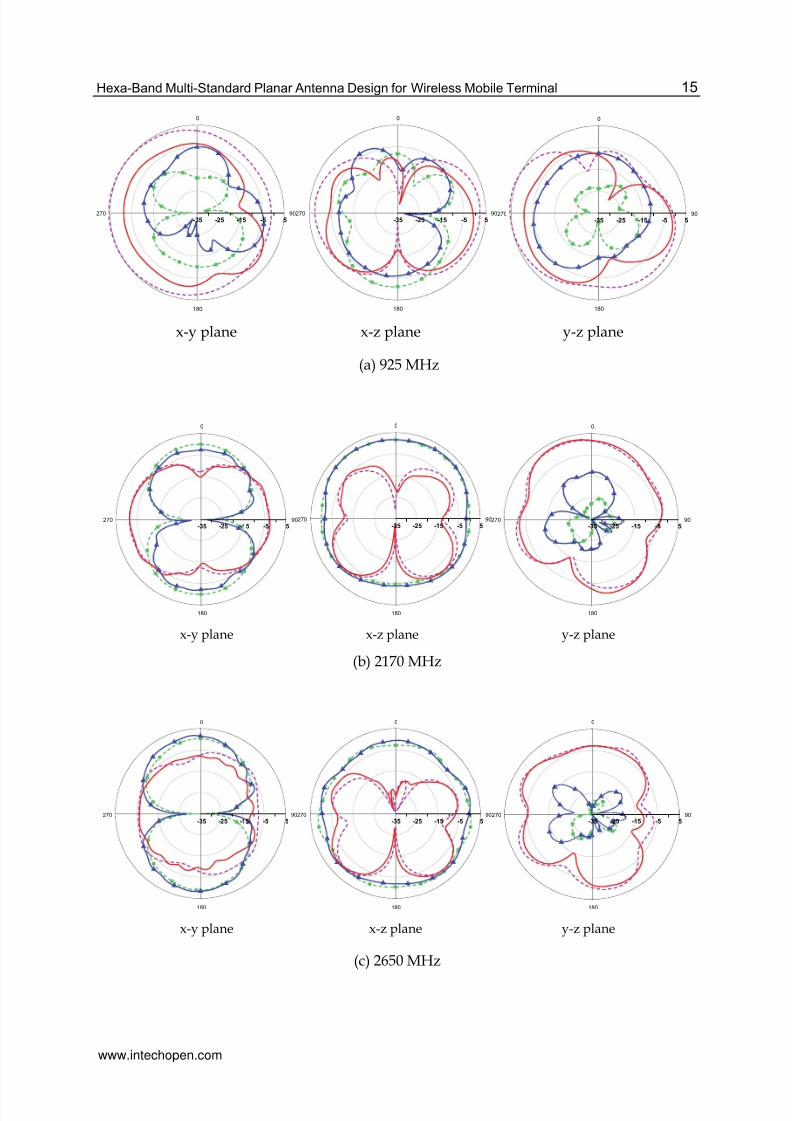
This study performed radiation-pattern and gain measurement in the anechoic chambers ofSGS Ltd. Taiwan, as shown in Fig. 14. Fig. 15 shows the measured and simulated radiationpatterns at the xy-cut, xz-cut, and yz-cut. The measured radiation patterns show a goodmatch to the simulation results except at 925MHz. In the small antenna measurement, the
patterns are easily affected by the feeding RF cable in the GSM band (Chen et al., 2005). Thiswork finds that the dual-polarization radiation-patterns have very suitable characteristicsfor portable devices. For the radiation shown in Fig. 14(a), more energy for Eθ is radiated inthe lower band as compared to Eφ. The Eφ field has some dips at 900 MHz on the xz-planeor 1800 MHz on the xy-plane. This is probably due to current cancellation on the strips andthe ground plane.
Fig. 14. Radiation Pattern measurement in a 3D anechoic chamber.
Findings also show a dipole-like pattern at the frequency 2170 MHz. Radiation patternsshown in Fig. 15(b) confirm this deduction. The radiation pattern of this mode is similar to asmall dipole oriented in the y–axis leading to a directional pattern in the E-plane (xy-plane,blue line) and omni-directional pattern in the H-plane (xz-plane, blue line), as Fig. 15(b),shows respectively. The resonators C and B at 2170 MHz have strong current distributionsalong the z-direction which also contribute to radiation fields. The radiation pattern of thiscurrent distribution is due to a small dipole oriented in the z–axis leading to a bidirectionalpattern in the E-plane (xz-plane, red line) and omni-directional pattern in the H-plane (xy-plane, red line), as Fig. 15(b), shows respectively. Findings also show an asymmetricradiation pattern at the U-NII band (5-6 GHz) and some variation and nulls, since differentmodes are excited in this U-NII band.
www.intechopen.com
8/17/2019 InTech-Hexa Band Multi Standard Planar Antenna Design for Wireless Mobile Terminal
http://slidepdf.com/reader/full/intech-hexa-band-multi-standard-planar-antenna-design-for-wireless-mobile-terminal 13/17
Hexa-Band Multi-Standard Planar Antenna Design for Wireless Mobile Terminal 15
0
90
180
270
-35 -25 -15 -5 5
0
90
180
270
-35 -25 -15 -5 5
0
90
180
270
-35 -25 -15 -5 5
x-y plane x-z plane y-z plane
(a) 925 MHz
0
90
180
270
-35 -25 -15 -5 5
0
90
180
270
-35 -25 -15 -5 5
0
90
180
270
-35 -25 -15 -5 5
x-y plane x-z plane y-z plane
(b) 2170 MHz
0
90
180
270
-35 -25 -15 -5 5
0
90
180
270
-35 -25 -15 -5 5
0
90
180
270
-35 -25 -15 -5 5
x-y plane x-z plane y-z plane
(c) 2650 MHz
www.intechopen.com

8/17/2019 InTech-Hexa Band Multi Standard Planar Antenna Design for Wireless Mobile Terminal
http://slidepdf.com/reader/full/intech-hexa-band-multi-standard-planar-antenna-design-for-wireless-mobile-terminal 14/17
Advanced Transmission Techniques in WiMAX16
0
90
180
270
-35 -25 -15 -5 5
0
90
180
270
-35 -25 -15 -5 5
0
90
180
270
-35 -25 -15 -5 5
x-y plane x-z plane y-z plane
(d) 5775 MHz
xy
z
Fig. 15. Measured and simulated radiation patterns in three cuts (a) 925 MHz (b) 2170 MHz
(c) 2650 MHz (d) 5775 MHz.
Frequency (MHz) 925 1710 1795 1920 1990
Peak Gain (dBi) -0.25 2.4 2.05 1.39 1.63
Average Gain (dBi) -1.96 1.10 -0.63 -0.01 -0.51
Efficiency 51.42% 61.94% 64.85% 70.35% 78.80%
Frequency 2170 2420 2650 5250 5800
Peak Gain 2.95 2.5 2.48 6.91 8.35
Average Gain 1.10 1.15 0.58 -0.31 -1.99
Efficiency 90.11% 86.83% 71.42% 70.24% 71.80%
Table 1. Measured three-dimensional peak gain, average gain, and radiation efficiency.
By using the commercial electromagnetic simulation software HFSS, this research carries outsimulations for the theoretical gains to investigate antenna performance and compare it withthe measured results (Chi, 2009). Good agreement confirms that the measured data areaccurate. The two-dimensional average gain is determined from pattern measurementsmade in the horizontal (azimuth) plane for both polarizations of the electric field. Theresults are then averaged over azimuth angles and normalized with respect to an idealisotropic radiator (Chen, 2007). Finally, Table 1 lists the measured peak gain, two-
Measured E-theta
Measured E-phi
Simulated E-theta
Simulated E-phi
www.intechopen.com

8/17/2019 InTech-Hexa Band Multi Standard Planar Antenna Design for Wireless Mobile Terminal
http://slidepdf.com/reader/full/intech-hexa-band-multi-standard-planar-antenna-design-for-wireless-mobile-terminal 15/17
Hexa-Band Multi-Standard Planar Antenna Design for Wireless Mobile Terminal 17
dimensional average gain and radiation efficiency for all the operation bands, showing thatall radiation efficiencies are over 50 percent, meeting the specification requirement.
4. Summary
This chapter reported a down-sized multiband inverted-F antenna to integrate the 3.5G andWLAN/WiMAX antenna systems. It is comprised of a dual-band antenna with one feedpoint and two parasitic elements to cover many mobile communication systems includingGSM900 /DCS /PCS /UMTS /WLAN/ WiMAX /HiperLAN2 /IEEE802.11a. Measuredparameters including return loss, radiation patterns, three-dimensional peak gain andaverage gain as well as radiation efficiency were presented to validate the proposed design.Since this antenna can be formed by a single plate, it is both low cost and easy to fabricate,making it suitable for any palm-sized mobile device applications.
5. References
C. Soras, M. Karaboikis, and G. T. V. Makios, "Analysis and design of an inverted-F antennaprinted on a PCMCIA card for the 2.4 GHz ISM band," IEEE Antenna's andpropagation magazine, vol. 44, no. 1, February 2002.
C. W. Chiu and F. L. Lin, "Compact dual-band PIFA with multi-resonators," ElectronicsLetters, vol. 38, pp. 538-540, June 2002.
C.-L. Liu, Y.-F. Lin, C.-M. Liang, S.-C. Pan, and H.-M. Chen, "Miniature Internal Penta-BandMonopole Antenna for Mobile Phones," IEEE Trans. Antennas Propag., vol. 58, no.3, March 2010.
D. Liu and B. Gaucher, "A new multiband antenna for WLAN/Cellular application,"Vehicular Technology Conference, vol. 1, 60th, pp. 243 - 246, Sept. 2004.
D. Liu and B. Gaucher, "A quadband antenna for laptop application," InternationalWorkshop on Antenna Technology, pp. 128-131, March 2007.
D.M. Nashaat, H. A. Elsadek, and H. Ghali, “Single feed compact quad -band PIFA antennafor wireless communication applications,” IEEE Trans. Antennas Propagat., vol. 53,No. 8, pp. 2631-2635, Aug. 2005.
H.-W. Hsieh, Y.-C. Lee, K.-K. Tiong, and J.-S. Sun, "Design of A Multiband Antenna forMobile Handset Operations," IEEE Antennas Wireless Propag. Lett., vol. 8, 2009.
J. Anguera, I. Sanz, J. Mumbrú, and C. Puente, "Multiband Handset Antenna with A ParallelExcitation of PIFA and Slot Radiators," IEEE Trans. Antennas Propag., vol. 58, no.2, February 2010.
K. Hirasawa and M. Haneishi, "Analysis, design and measurement of small and low profileantennas," ch.5, Norwood, MA, Artech House, 1922.
K.-L. Wong, L.-C. Chou, and C.-M. Su, "Dual-band flat-plate antenna with a shortedparasitic element for laptop applications," IEEE Transactions on Antennas andPropagation, vol. 53, no. 1, pp. 539-544, January 2005.
M. Ali and G. J. Hayes, "Analysis of intergated inverted-F antennas for bluetoothapplications," IEEE International symposium on antenna and propagation, 2000.
M. K. Karkkainen, “Meandered multiband PIFA with coplanar parasitic patches,” IEEEMicrow. Wireless Compon. Lett., vol.15, pp. 630-632, Oct. 2005.
www.intechopen.com

8/17/2019 InTech-Hexa Band Multi Standard Planar Antenna Design for Wireless Mobile Terminal
http://slidepdf.com/reader/full/intech-hexa-band-multi-standard-planar-antenna-design-for-wireless-mobile-terminal 16/17
Advanced Transmission Techniques in WiMAX18
P. Ciais, R. Staraj, G. Kossiavas, and C. Luxey, "Design of an internal quad-band antenna formobile phones," IEEE Microwave and wireless components letters, vol. 14, no. 4,April 2004.
P. Kumar.m, S. Kumar, R. Jyoti, V. Reddy, and P. Rao1, "Novel Structural Design for
Compact and Broadband Patch Antenna," 2010 International Workshop onAntenna Technology (iWAT), 1-3 March 2010.
P.Nepa, G. Manara, A. A. Serra, and G. Nenna, "Multiband PIFA for WLAN mobileterminals," IEEE antenna and wireless propagation letters, vol. 4, 2005.
Q. Rao and W. Geyi, "Compact Multiband Antenna for Handheld Devices," IEEE Trans.Antennas Propag., vol. 57, no. 10, October 2009.
R. Bancroft, "Development and integration of a commercially viable 802.11a/b/g HiperLan/WLAN antenna into laptop computers," Antennas and Propagation SocietyInternational Symposium, vol. 4A, pp. 231- 234, July 2005.
R. King, C. W. Harisson, and D. H. Denton, "Transmission-line missile antenna," IRE Trans.Antenna Propagation, vol. 8, no. 1, pp. 88-90, 1960.
S. Hong, W. Kim, H. Park, S. Kahng, and J. Choi, "Design of An Internal MultiresonantMonopole Antenna for GSM900/DCS1800/US-PCS/S-DMB Operation," IEEETrans. Antennas Propag., vol. 56, no. 5, May 2008.
S.W. Su and J.H. Chou, “Internal 3G and WLAN/WiMAX antennas integrated in palm-sizedmobile devices,” Microw. Opt. Technol. Lett., vol. 50, no. 1, pp. 29-31, Jan. 2008.
T. K. Nguyen, B. Kim, H. Choo, and I. Park, "Multiband dual Spiral Stripline-LoadedMonopole Antenna," IEEE Antennas Wireless Propag. Lett., vol. 8, 2009.
T. Taga and K. Tsunekawa, "Performance analysis pf a built-in planar inverted-F antenna for800MHz and portable radio units," IEEE Trans. on selected areas incommunications, vol. SAC-5, no. 5, June 1987.
W. X. Li, X. Liu, and S. Li, "Design of A Broadband and Multiband Planar Inverted-FAntenna," 2010 International Conference on Communications and MobileComputing, vol. 2, 12-14 April 2010.
X. Wang, W. Chen, and Z. Feng, "Multiband antenna with parasitic branches for laptopapplications," Electronics letters, vol. 43, no. 19, 13th, September 2007.
Y. J., Chi, “Design of internal multiband antennas for portable devices,” Master Thesis,National Ilan University, June 2009
Y.-C. Yu and J.-H. Tarng, "A Novel Modified Multiband Planar Inverted-F Antenna," IEEEAntennas Wireless Propag. Lett., vol. 8, 2009.
Y.-X. Guo and H. S. Tan, "New compact six-band internal antenna," IEEE antenna andwireless propagation letters, vol. 3, 2004.
Y.-X. Guo, I. Ang, and M. Y. W. Chia, "Compact internal multiband antennas for mobilehandsets," IEEE antenna and wireless propogation letters, vol. 2, 2003.
Y.-X. Guo, M. Y. W. Chia, and Z. N. Chen, "Miniature Built-In Multiband Antennas forMobile Handsets," IEEE Trans. Antennas Propag., vol. 52, no. 8, August 2004.
Z. N. Chen, Antennas for Portable Devices, pp.125-126, John Wiley & Sons, Inc. 2007.Z. N. Chen, N. Yang, Y. X. Guo, and M. Y. W. Chia, “An investigation into measurement of
handset antennas,” IEEE. Trans. Instrum. Meas., vol. 54, no.3, pp. 1100–1110, June 2005.Zhi Ning Chen, "Antennas for Portable Devices," John Wiley & Sons, Inc. 2007, ch.4, pp.115-116.
www.intechopen.com

8/17/2019 InTech-Hexa Band Multi Standard Planar Antenna Design for Wireless Mobile Terminal
http://slidepdf.com/reader/full/intech-hexa-band-multi-standard-planar-antenna-design-for-wireless-mobile-terminal 17/17
Advanced Transmission Techniques in WiMAX
Edited by Dr. Roberto Hincapie
ISBN 978-953-307-965-3
Hard cover, 336 pages
Publisher InTech
Published online 18, January, 2012
Published in print edition January, 2012
InTech Europe
University Campus STeP Ri
Slavka Krautzeka 83/A
51000 Rijeka, CroatiaPhone: +385 (51) 770 447
Fax: +385 (51) 686 166
www.intechopen.com
InTech China
Unit 405, Office Block, Hotel Equatorial Shanghai
No.65, Yan An Road (West), Shanghai, 200040, China
Phone: +86-21-62489820
Fax: +86-21-62489821
This book has been prepared to present the state of the art on WiMAX Technology. The focus of the book is
the physical layer, and it collects the contributions of many important researchers around the world. So many
different works on WiMAX show the great worldwide importance of WiMAX as a wireless broadband access
technology. This book is intended for readers interested in the transmission process under WiMAX. All
chapters include both theoretical and technical information, which provides an in-depth review of the most
recent advances in the field, for engineers and researchers, and other readers interested in WiMAX.
How to reference
In order to correctly reference this scholarly work, feel free to copy and paste the following:
Yu-Jen Chi and Chien-Wen Chiu (2012). Hexa-Band Multi-Standard Planar Antenna Design for Wireless
Mobile Terminal, Advanced Transmission Techniques in WiMAX, Dr. Roberto Hincapie (Ed.), ISBN: 978-953-
307-965-3, InTech, Available from: http://www.intechopen.com/books/advanced-transmission-techniques-in-
wimax/hexa-band-multi-standard-planar-antenna-design-for-wireless-mobile-terminal