Embed Size (px)
Citation preview

2000 – 2002 Celica GTS Intake Manifold Installation Guide
1 | P a g e Revision 1.01
Intake Manifold Installation Guide
2000 – 2002 Celica GTS

2000 – 2002 Celica GTS Intake Manifold Installation Guide
2 | P a g e Revision 1.01
Toyota Part Numbers you might need:
IAC Valve gasket – P/N 22215-7A680
Intake Manifold Gasket – P/N 17177-88600
IAC Mounting screws – P/N 90079-10012
IMPORTANT!! READ THIS AND DO THIS BEFORE INSTALLATION!!!
Preparation Instructions:
1 - Thoroughly clean your Q45 Throttle Body with Carb / Throttle body cleaner and dry
2 – Inspect your DD Performance Research Intake Manifold. Be sure to clean thoroughly to ensure there is no dust or debris in the plenum, runners, or IAC mounting location.
3 – Be sure to install hose barbs and throttle cable mount on new DD Performance Research Intake Manifold prior to bolting it to the vehicle
4 – Use Teflon tape on hose barb threads to ensure a 100% seal
5 - Store clean manifold and throttle body in a new trash bag and put somewhere safe until called to install them
6 - Read through the instructions and be sure that you have all tools necessary.
7 – Use gloves and eye protection and remove jewelery while working to prevent injury
8 – Once installation is complete double check that nothing can interfere with the movement of the throttle cable or bellcrank. If the throttle sticks open uncontrollable acceleration will result.
Things you need that DD Performance Research does NOT provide:
Brake clean, Carb clean, clean rags, small vacuum plugs, Q45 throttle body, Permatex gasket spray, Blue lockite thread adhesive, Teflon tape, TB – CAI coupler (4” to 3”), Metric hand tools
Cosmetic Repair:
If at any time your DD Performance Research intake manifold looses its shine you can clean it with blue magic or mothers metal polish and a mothers power ball or power cone and some terrycloth towels. If you have a deep scratch or want to achieve a perfectly smooth texture sand first with 400 grit wet dry paper, and then 800 and 1000 grit paper. After 1000 grit polish with one of the compounds noted above.
2000 – 2002 Celica GTS Intake Manifold Installation Guide
3 | P a g e Revision 1.01
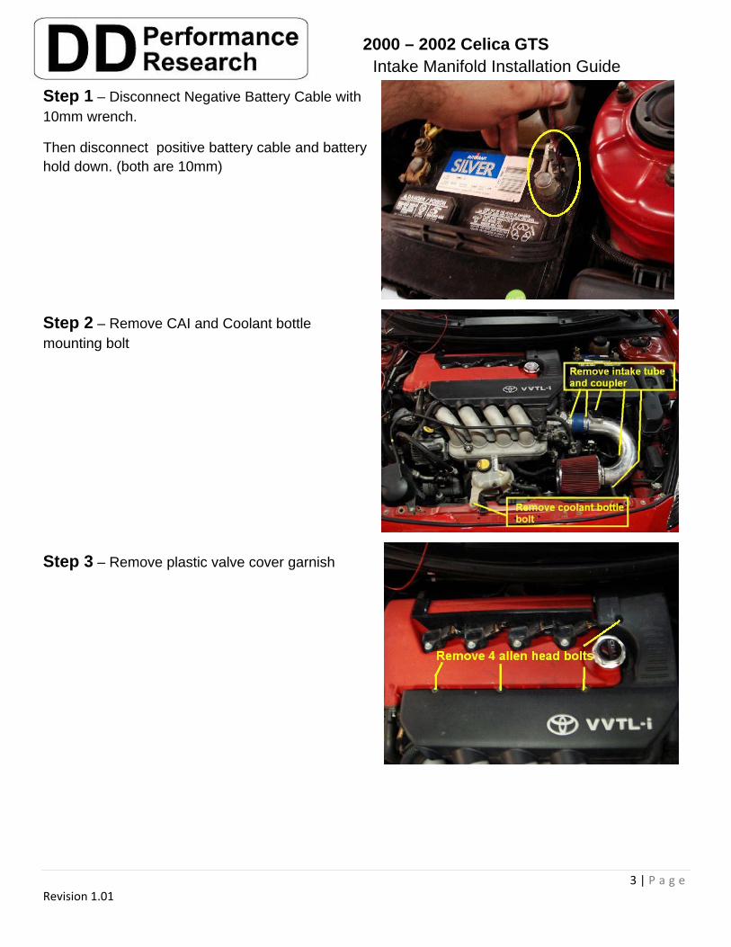
Step 1 – Disconnect Negative Battery Cable with 10mm wrench.
Then disconnect positive battery cable and battery hold down. (both are 10mm)
Step 2 – Remove CAI and Coolant bottle mounting bolt
Step 3 – Remove plastic valve cover garnish
2000 – 2002 Celica GTS Intake Manifold Installation Guide
4 | P a g e Revision 1.01
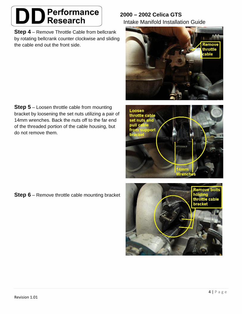
Step 4 – Remove Throttle Cable from bellcrank by rotating bellcrank counter clockwise and sliding the cable end out the front side.
Step 5 – Loosen throttle cable from mounting bracket by loosening the set nuts utilizing a pair of 14mm wrenches. Back the nuts off to the far end of the threaded portion of the cable housing, but do not remove them.
Step 6 – Remove throttle cable mounting bracket
2000 – 2002 Celica GTS Intake Manifold Installation Guide
5 | P a g e Revision 1.01
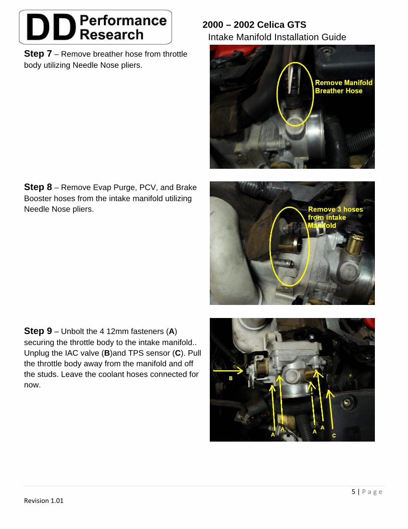
Step 7 – Remove breather hose from throttle body utilizing Needle Nose pliers.
Step 8 – Remove Evap Purge, PCV, and Brake Booster hoses from the intake manifold utilizing Needle Nose pliers.
Step 9 – Unbolt the 4 12mm fasteners (A) securing the throttle body to the intake manifold.. Unplug the IAC valve (B)and TPS sensor (C). Pull the throttle body away from the manifold and off the studs. Leave the coolant hoses connected for now.
2000 – 2002 Celica GTS Intake Manifold Installation Guide
6 | P a g e Revision 1.01
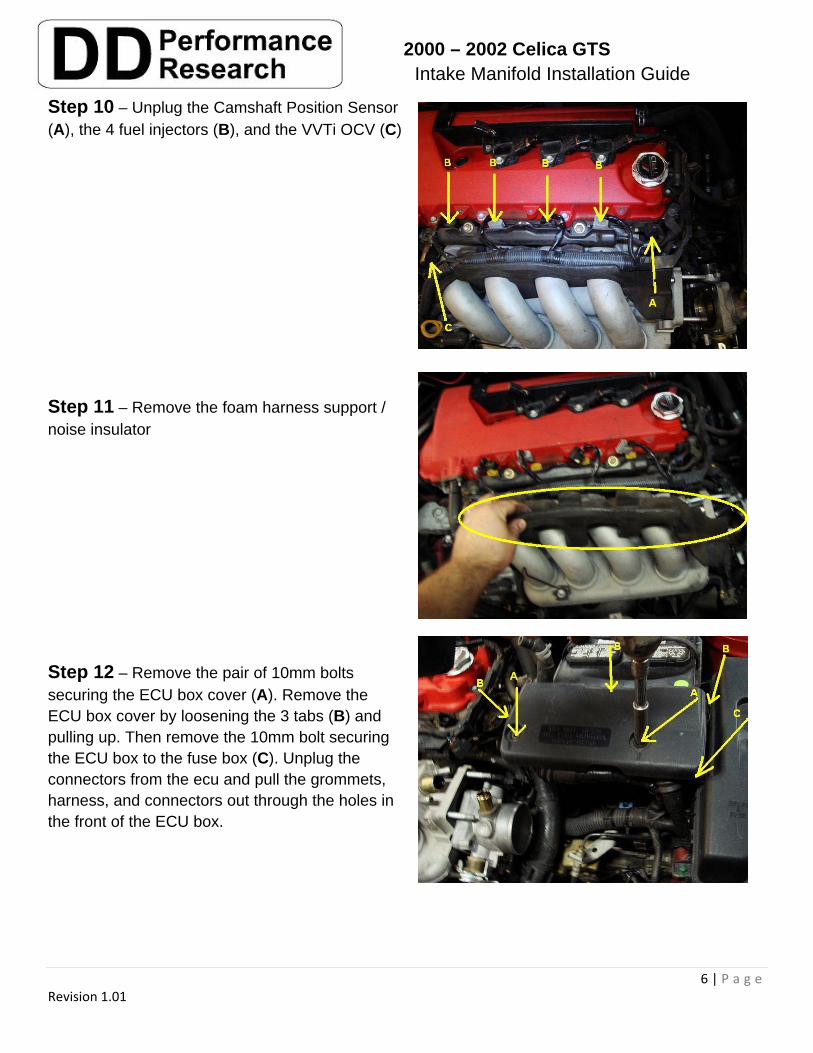
Step 10 – Unplug the Camshaft Position Sensor (A), the 4 fuel injectors (B), and the VVTi OCV (C)
Step 11 – Remove the foam harness support / noise insulator
Step 12 – Remove the pair of 10mm bolts securing the ECU box cover (A). Remove the ECU box cover by loosening the 3 tabs (B) and pulling up. Then remove the 10mm bolt securing the ECU box to the fuse box (C). Unplug the connectors from the ecu and pull the grommets, harness, and connectors out through the holes in the front of the ECU box.
2000 – 2002 Celica GTS Intake Manifold Installation Guide
7 | P a g e Revision 1.01
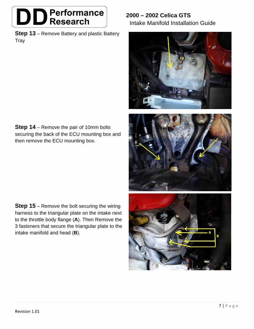
Step 13 – Remove Battery and plastic Battery Tray
Step 14 – Remove the pair of 10mm bolts securing the back of the ECU mounting box and then remove the ECU mounting box.
Step 15 – Remove the bolt securing the wiring harness to the triangular plate on the intake next to the throttle body flange (A). Then Remove the 3 fasteners that secure the triangular plate to the intake manifold and head (B).
2000 – 2002 Celica GTS Intake Manifold Installation Guide
8 | P a g e Revision 1.01
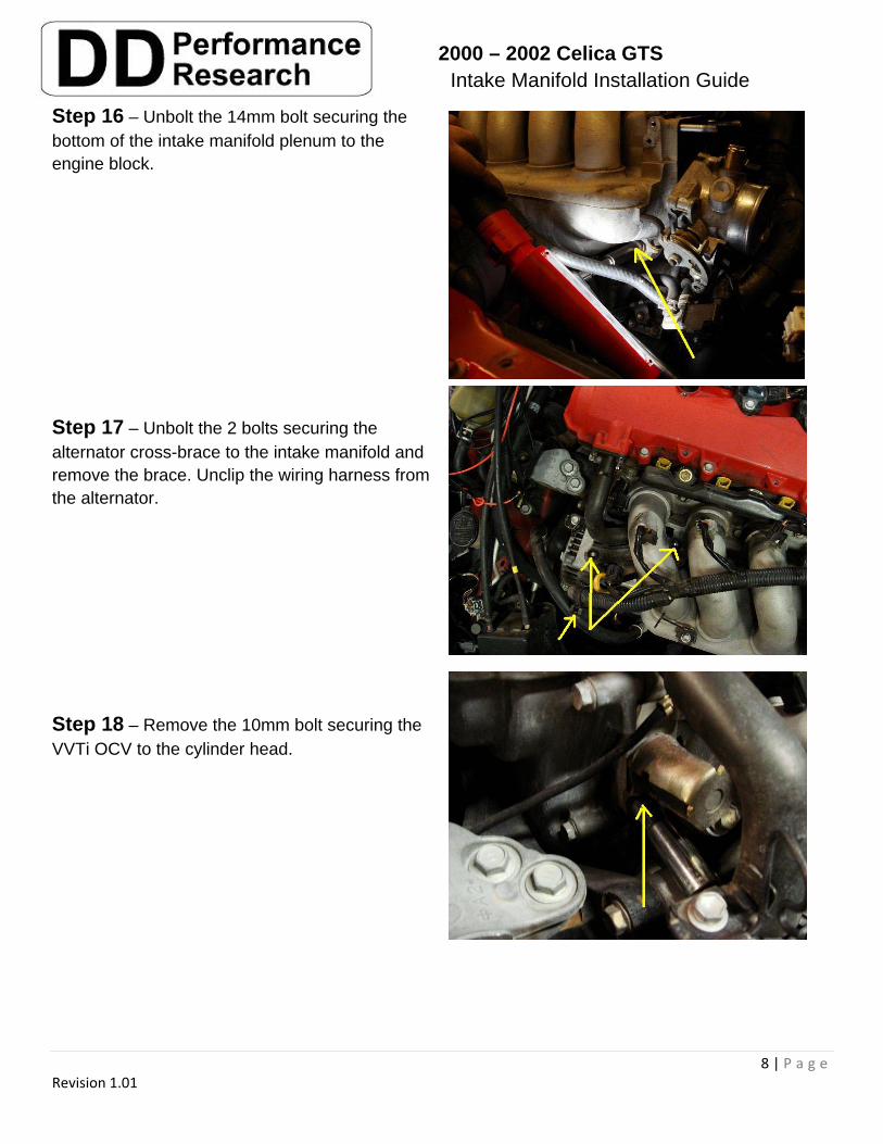
Step 16 – Unbolt the 14mm bolt securing the bottom of the intake manifold plenum to the engine block.
Step 17 – Unbolt the 2 bolts securing the alternator cross-brace to the intake manifold and remove the brace. Unclip the wiring harness from the alternator.
Step 18 – Remove the 10mm bolt securing the VVTi OCV to the cylinder head.
2000 – 2002 Celica GTS Intake Manifold Installation Guide
9 | P a g e Revision 1.01
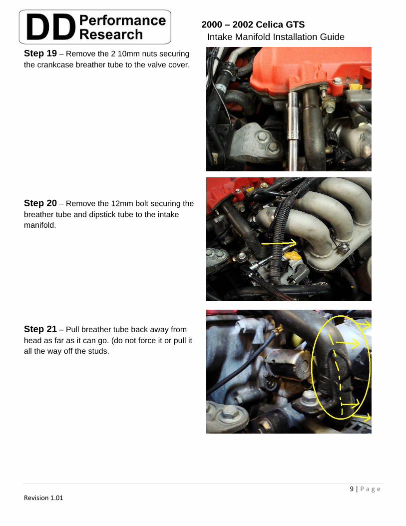
Step 19 – Remove the 2 10mm nuts securing the crankcase breather tube to the valve cover.
Step 20 – Remove the 12mm bolt securing the breather tube and dipstick tube to the intake manifold.
Step 21 – Pull breather tube back away from head as far as it can go. (do not force it or pull it all the way off the studs.
2000 – 2002 Celica GTS Intake Manifold Installation Guide
10 | P a g e Revision 1.01
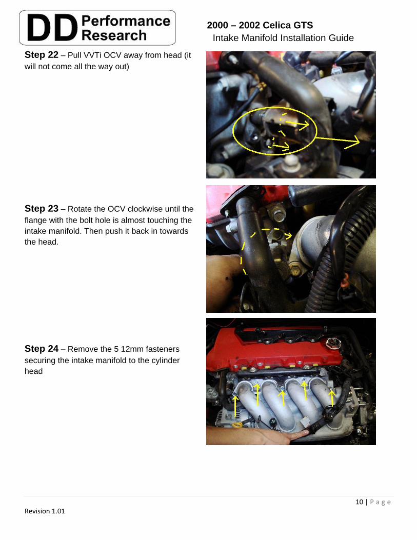
Step 22 – Pull VVTi OCV away from head (it will not come all the way out)
Step 23 – Rotate the OCV clockwise until the flange with the bolt hole is almost touching the intake manifold. Then push it back in towards the head.
Step 24 – Remove the 5 12mm fasteners securing the intake manifold to the cylinder head
2000 – 2002 Celica GTS Intake Manifold Installation Guide
11 | P a g e Revision 1.01
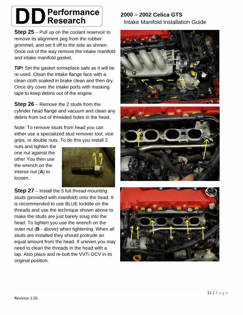
Step 25 – Pull up on the coolant reservoir to remove its alignment peg from the rubber grommet, and set it off to the side as shown. Once out of the way remove the intake manifold and intake manifold gasket.
TIP! Set the gasket someplace safe as it will be re-used. Clean the intake flange face with a clean cloth soaked in brake clean and then dry. Once dry cover the intake ports with masking tape to keep debris out of the engine.
Step 26 – Remove the 2 studs from the cylinder head flange and vacuum and clean any debris from out of threaded holes in the head.
Note: To remove studs from head you can either use a specialized stud remover tool, vice grips, or double nuts. To do this you install 2 nuts and tighten the one nut against the other You then use the wrench on the interior nut (A) to loosen.
Step 27 – Install the 5 full thread mounting studs (provided with manifold) onto the head. It is recommended to use BLUE locktite on the threads and use the technique shown above to make the studs are just barely snug into the head. To tighten you use the wrench on the outer nut (B - above) when tightening. When all studs are installed they should protrude an equal amount from the head. If uneven you may need to clean the threads in the head with a tap. Also place and re-bolt the VVTi OCV in its original position.
2000 – 2002 Celica GTS Intake Manifold Installation Guide
12 | P a g e Revision 1.01
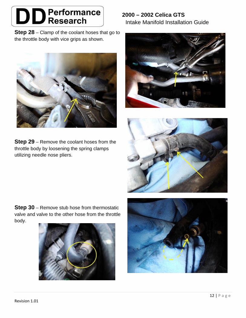
Step 28 – Clamp of the coolant hoses that go to the throttle body with vice grips as shown.
Step 29 – Remove the coolant hoses from the throttle body by loosening the spring clamps utilizing needle nose pliers.
Step 30 – Remove stub hose from thermostatic valve and valve to the other hose from the throttle body.
2000 – 2002 Celica GTS Intake Manifold Installation Guide
13 | P a g e Revision 1.01
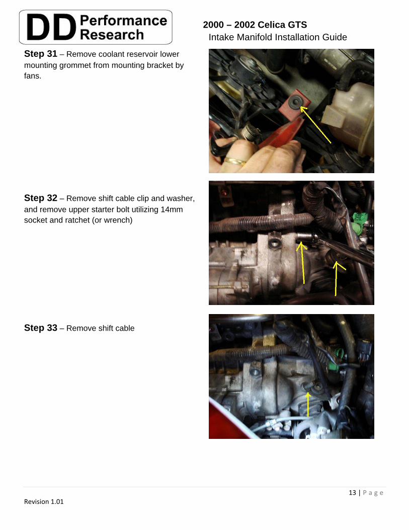
Step 31 – Remove coolant reservoir lower mounting grommet from mounting bracket by fans.
Step 32 – Remove shift cable clip and washer, and remove upper starter bolt utilizing 14mm socket and ratchet (or wrench)
Step 33 – Remove shift cable
2000 – 2002 Celica GTS Intake Manifold Installation Guide
14 | P a g e Revision 1.01
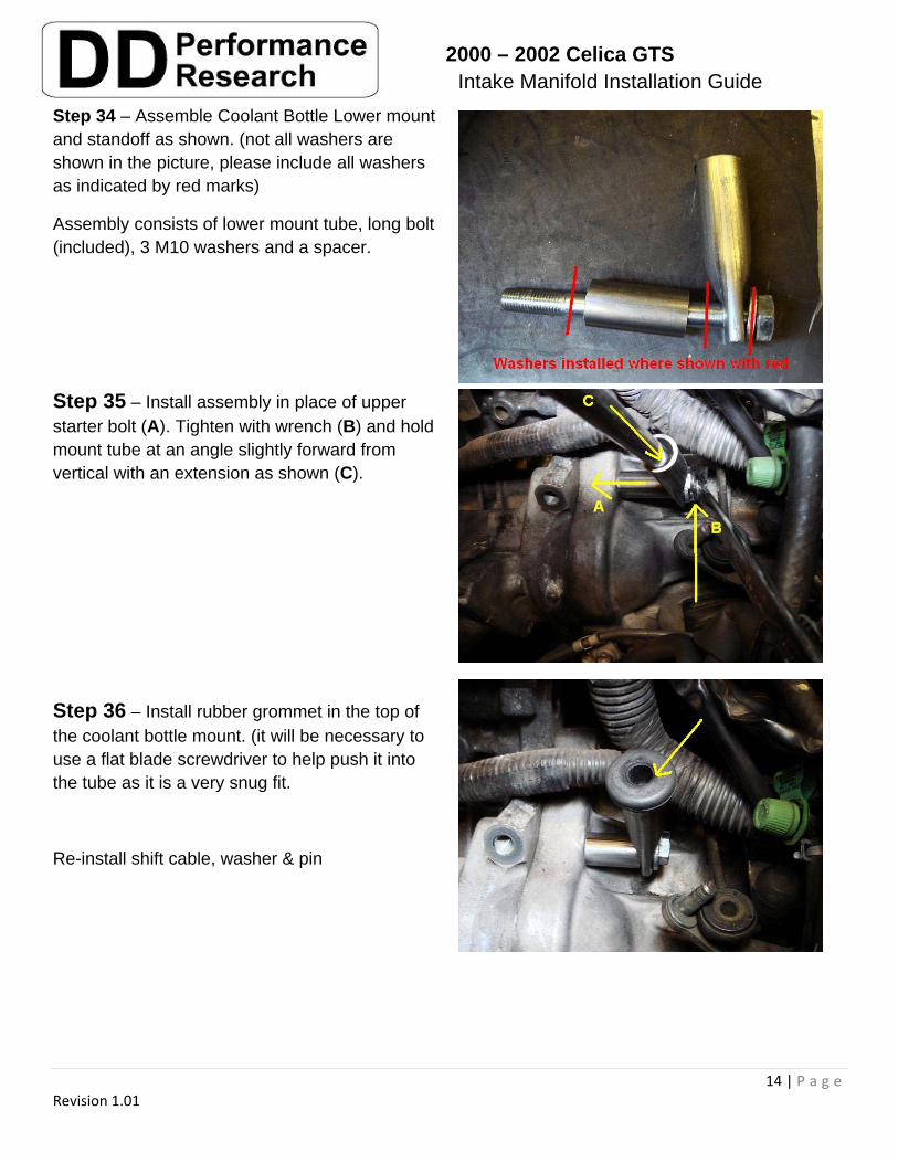
Step 34 – Assemble Coolant Bottle Lower mount and standoff as shown. (not all washers are shown in the picture, please include all washers as indicated by red marks)
Assembly consists of lower mount tube, long bolt (included), 3 M10 washers and a spacer.
Step 35 – Install assembly in place of upper starter bolt (A). Tighten with wrench (B) and hold mount tube at an angle slightly forward from vertical with an extension as shown (C).
Step 36 – Install rubber grommet in the top of the coolant bottle mount. (it will be necessary to use a flat blade screwdriver to help push it into the tube as it is a very snug fit.
Re-install shift cable, washer & pin
2000 – 2002 Celica GTS Intake Manifold Installation Guide
15 | P a g e Revision 1.01
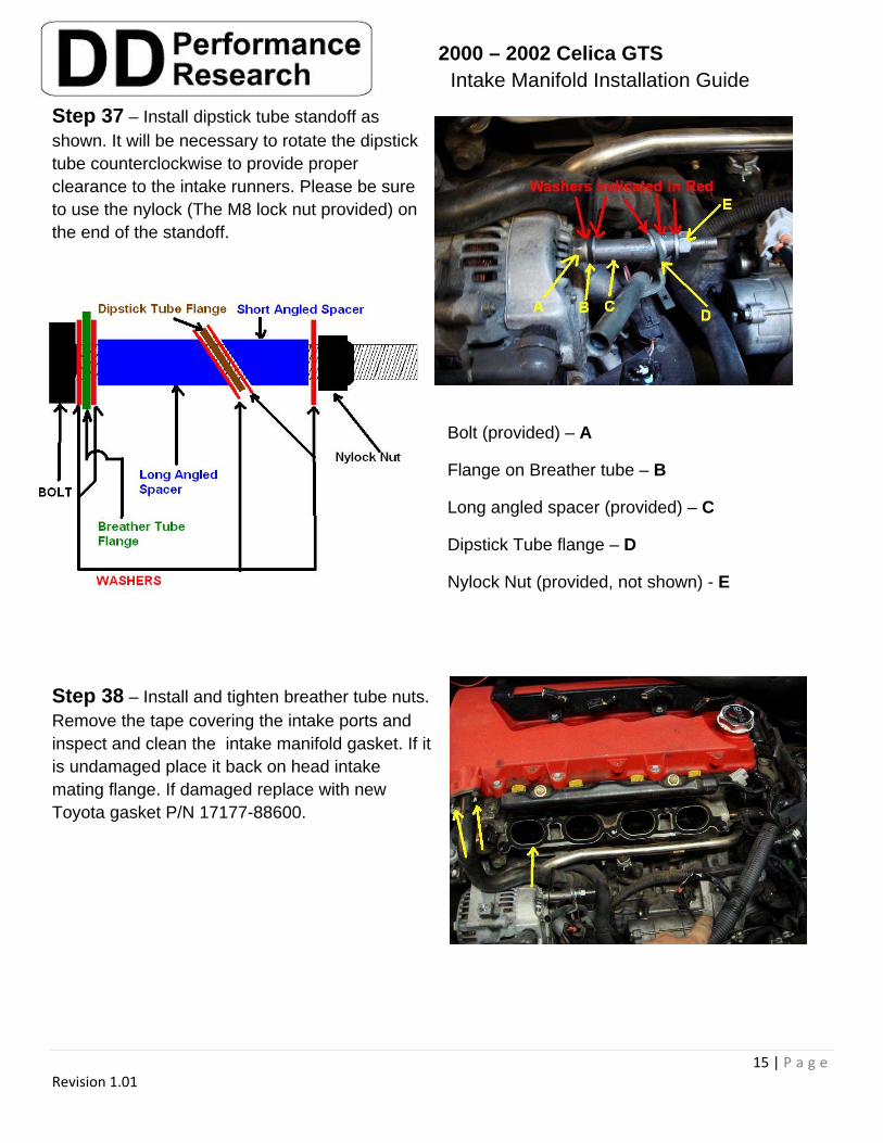
Step 37 – Install dipstick tube standoff as shown. It will be necessary to rotate the dipstick tube counterclockwise to provide proper clearance to the intake runners. Please be sure to use the nylock (The M8 lock nut provided) on the end of the standoff.
Bolt (provided) – A
Flange on Breather tube – B
Long angled spacer (provided) – C
Dipstick Tube flange – D
Nylock Nut (provided, not shown) - E
Step 38 – Install and tighten breather tube nuts. Remove the tape covering the intake ports and inspect and clean the intake manifold gasket. If it is undamaged place it back on head intake mating flange. If damaged replace with new Toyota gasket P/N 17177-88600.
2000 – 2002 Celica GTS Intake Manifold Installation Guide
16 | P a g e Revision 1.01
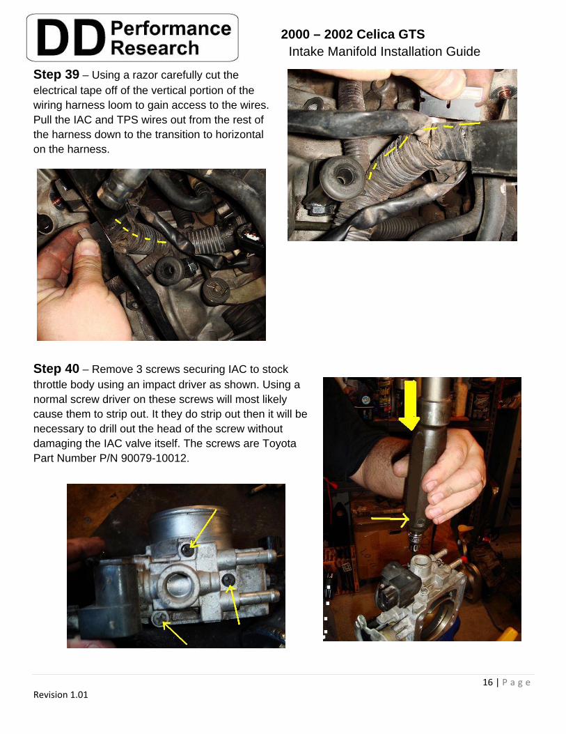
Step 39 – Using a razor carefully cut the electrical tape off of the vertical portion of the wiring harness loom to gain access to the wires. Pull the IAC and TPS wires out from the rest of the harness down to the transition to horizontal on the harness.
Step 40 – Remove 3 screws securing IAC to stock throttle body using an impact driver as shown. Using a normal screw driver on these screws will most likely cause them to strip out. It they do strip out then it will be necessary to drill out the head of the screw without damaging the IAC valve itself. The screws are Toyota Part Number P/N 90079-10012.
2000 – 2002 Celica GTS Intake Manifold Installation Guide
17 | P a g e Revision 1.01
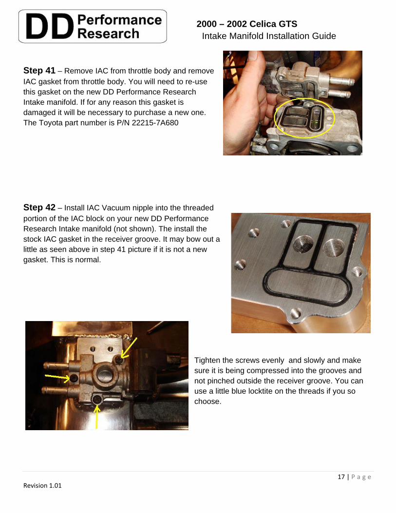
Step 41 – Remove IAC from throttle body and remove IAC gasket from throttle body. You will need to re-use this gasket on the new DD Performance Research Intake manifold. If for any reason this gasket is damaged it will be necessary to purchase a new one. The Toyota part number is P/N 22215-7A680
Step 42 – Install IAC Vacuum nipple into the threaded portion of the IAC block on your new DD Performance Research Intake manifold (not shown). The install the stock IAC gasket in the receiver groove. It may bow out a little as seen above in step 41 picture if it is not a new gasket. This is normal.
Tighten the screws evenly and slowly and make sure it is being compressed into the grooves and not pinched outside the receiver groove. You can use a little blue locktite on the threads if you so choose.
2000 – 2002 Celica GTS Intake Manifold Installation Guide
18 | P a g e Revision 1.01
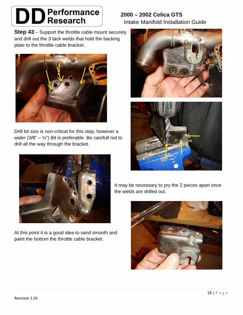
Step 43 – Support the throttle cable mount securely and drill out the 3 tack welds that hold the backing plate to the throttle cable bracket.
Drill bit size is non-critical for this step, however a wider (3/8” – ½”) Bit is preferable. Be carefull not to drill all the way through the bracket.
It may be necessary to pry the 2 pieces apart once the welds are drilled out.
At this point it is a good idea to sand smooth and paint the bottom the throttle cable bracket.
2000 – 2002 Celica GTS Intake Manifold Installation Guide
19 | P a g e Revision 1.01
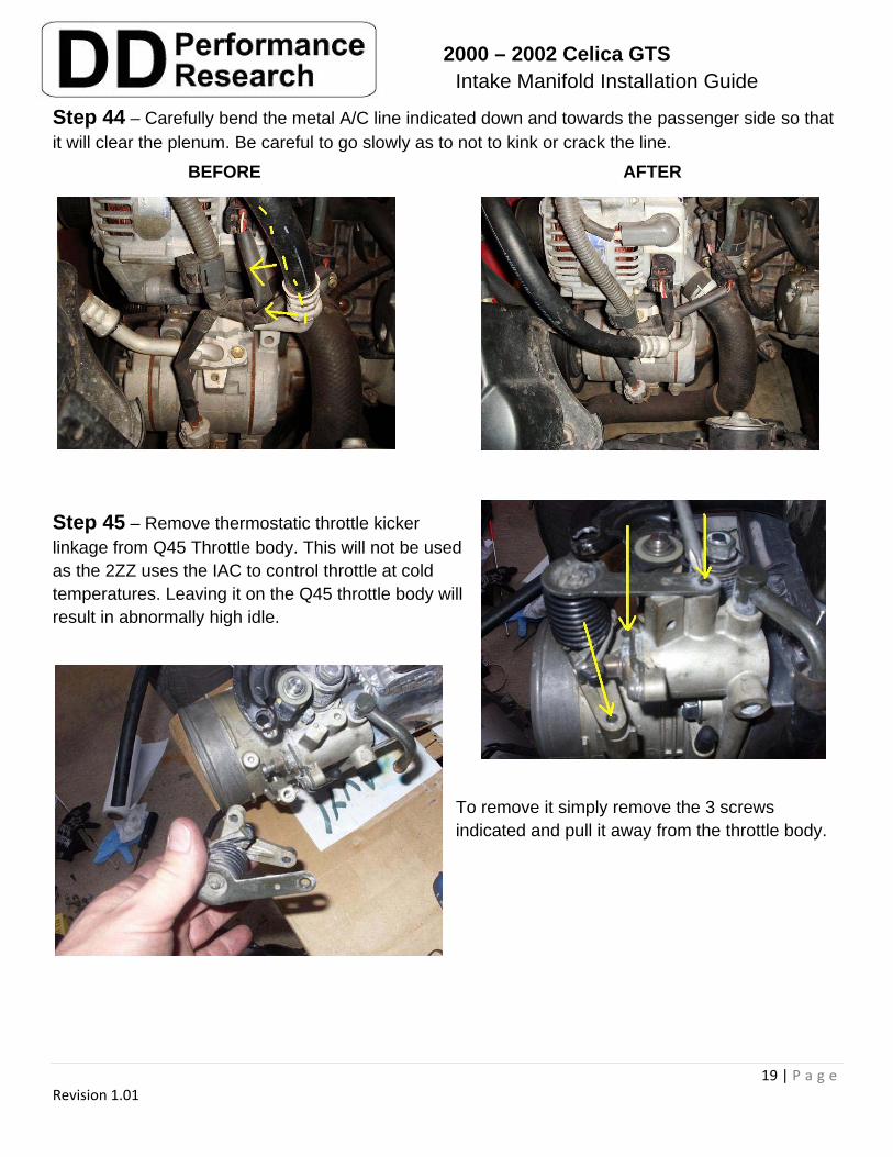
Step 44 – Carefully bend the metal A/C line indicated down and towards the passenger side so that it will clear the plenum. Be careful to go slowly as to not to kink or crack the line.
Step 45 – Remove thermostatic throttle kicker linkage from Q45 Throttle body. This will not be used as the 2ZZ uses the IAC to control throttle at cold temperatures. Leaving it on the Q45 throttle body will result in abnormally high idle.
To remove it simply remove the 3 screws indicated and pull it away from the throttle body.
BEFORE AFTER
2000 – 2002 Celica GTS Intake Manifold Installation Guide
20 | P a g e Revision 1.01
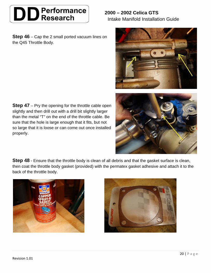
Step 46 – Cap the 2 small ported vacuum lines on the Q45 Throttle Body.
Step 47 – Pry the opening for the throttle cable open slightly and then drill out with a drill bit slightly larger than the metal “T” on the end of the throttle cable. Be sure that the hole is large enough that it fits, but not so large that it is loose or can come out once installed properly.
Step 48 - Ensure that the throttle body is clean of all debris and that the gasket surface is clean, then coat the throttle body gasket (provided) with the permatex gasket adhesive and attach it to the back of the throttle body.
2000 – 2002 Celica GTS Intake Manifold Installation Guide
21 | P a g e Revision 1.01
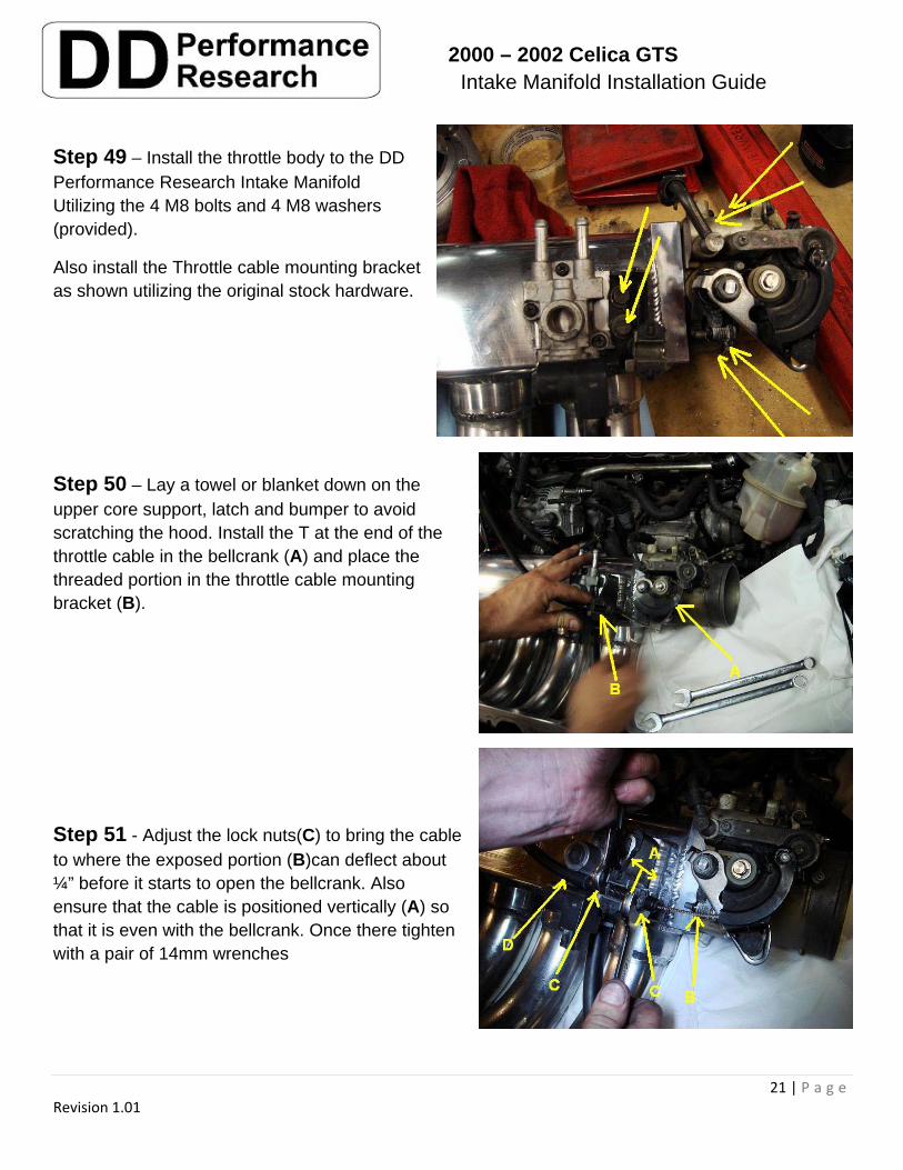
Step 49 – Install the throttle body to the DD Performance Research Intake Manifold Utilizing the 4 M8 bolts and 4 M8 washers (provided).
Also install the Throttle cable mounting bracket as shown utilizing the original stock hardware.
Step 50 – Lay a towel or blanket down on the upper core support, latch and bumper to avoid scratching the hood. Install the T at the end of the throttle cable in the bellcrank (A) and place the threaded portion in the throttle cable mounting bracket (B).
Step 51 - Adjust the lock nuts(C) to bring the cable to where the exposed portion (B)can deflect about ¼” before it starts to open the bellcrank. Also ensure that the cable is positioned vertically (A) so that it is even with the bellcrank. Once there tighten with a pair of 14mm wrenches
2000 – 2002 Celica GTS Intake Manifold Installation Guide
22 | P a g e Revision 1.01
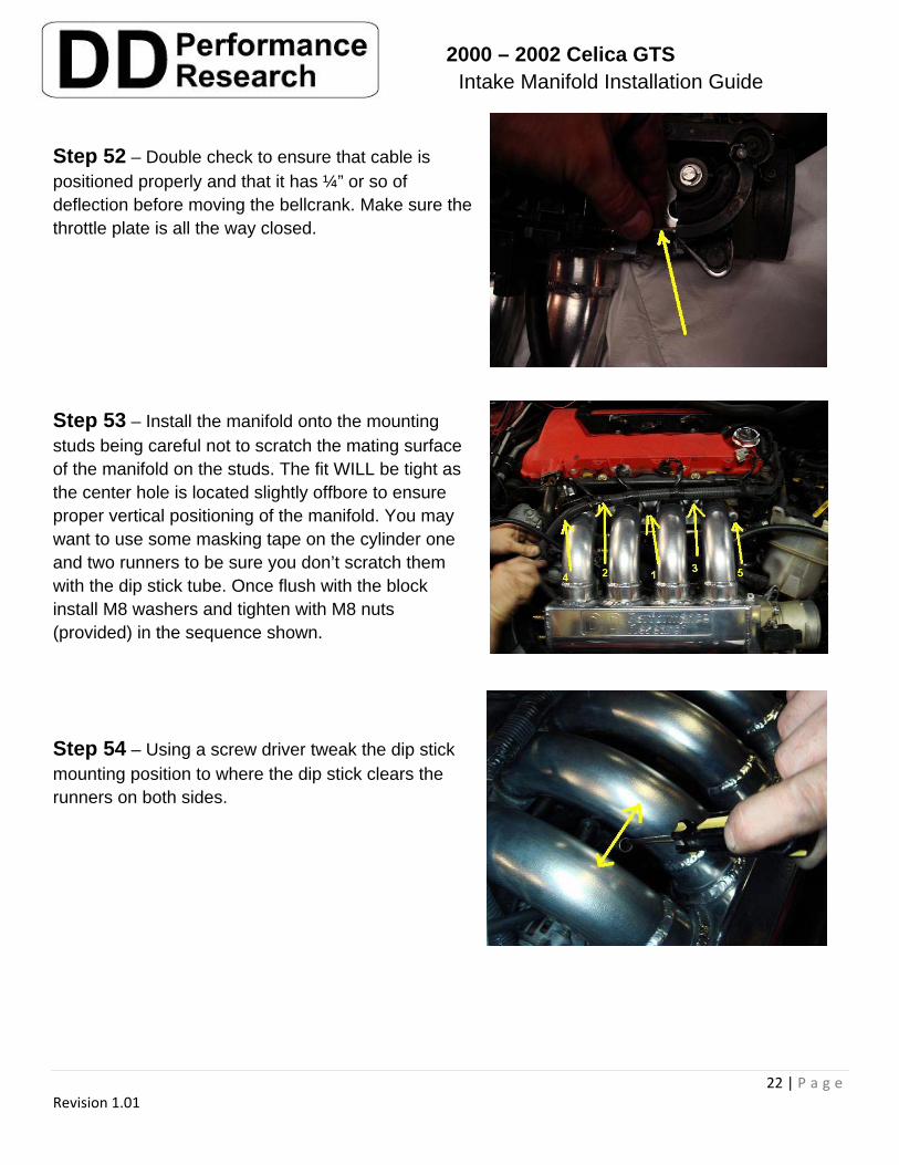
Step 52 – Double check to ensure that cable is positioned properly and that it has ¼” or so of deflection before moving the bellcrank. Make sure the throttle plate is all the way closed.
Step 53 – Install the manifold onto the mounting studs being careful not to scratch the mating surface of the manifold on the studs. The fit WILL be tight as the center hole is located slightly offbore to ensure proper vertical positioning of the manifold. You may want to use some masking tape on the cylinder one and two runners to be sure you don’t scratch them with the dip stick tube. Once flush with the block install M8 washers and tighten with M8 nuts (provided) in the sequence shown.
Step 54 – Using a screw driver tweak the dip stick mounting position to where the dip stick clears the runners on both sides.
2000 – 2002 Celica GTS Intake Manifold Installation Guide
23 | P a g e Revision 1.01
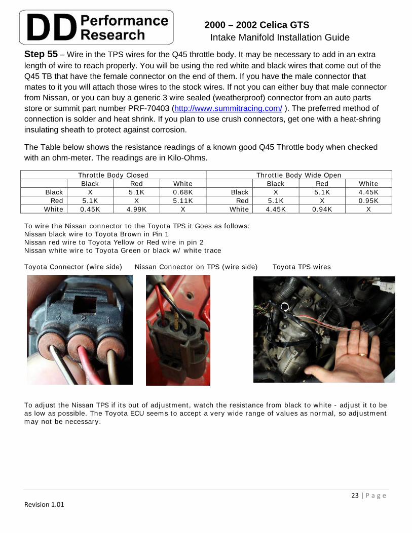
Step 55 – Wire in the TPS wires for the Q45 throttle body. It may be necessary to add in an extra length of wire to reach properly. You will be using the red white and black wires that come out of the Q45 TB that have the female connector on the end of them. If you have the male connector that mates to it you will attach those wires to the stock wires. If not you can either buy that male connector from Nissan, or you can buy a generic 3 wire sealed (weatherproof) connector from an auto parts store or summit part number PRF-70403 (http://www.summitracing.com/ ). The preferred method of connection is solder and heat shrink. If you plan to use crush connectors, get one with a heat-shring insulating sheath to protect against corrosion.
The Table below shows the resistance readings of a known good Q45 Throttle body when checked with an ohm-meter. The readings are in Kilo-Ohms.
Throttle Body Closed Throttle Body Wide Open Black Red White Black Red White
Black X 5.1K 0.68K Black X 5.1K 4.45K Red 5.1K X 5.11K Red 5.1K X 0.95K
White 0.45K 4.99K X White 4.45K 0.94K X To wire the Nissan connector to the Toyota TPS it Goes as follows: Nissan black wire to Toyota Brown in Pin 1 Nissan red wire to Toyota Yellow or Red wire in pin 2 Nissan white wire to Toyota Green or black w/ white trace Toyota Connector (wire side) Nissan Connector on TPS (wire side) Toyota TPS wires
To adjust the Nissan TPS if its out of adjustment, watch the resistance from black to white - adjust it to be as low as possible. The Toyota ECU seems to accept a very wide range of values as normal, so adjustment may not be necessary.
2000 – 2002 Celica GTS Intake Manifold Installation Guide
24 | P a g e Revision 1.01
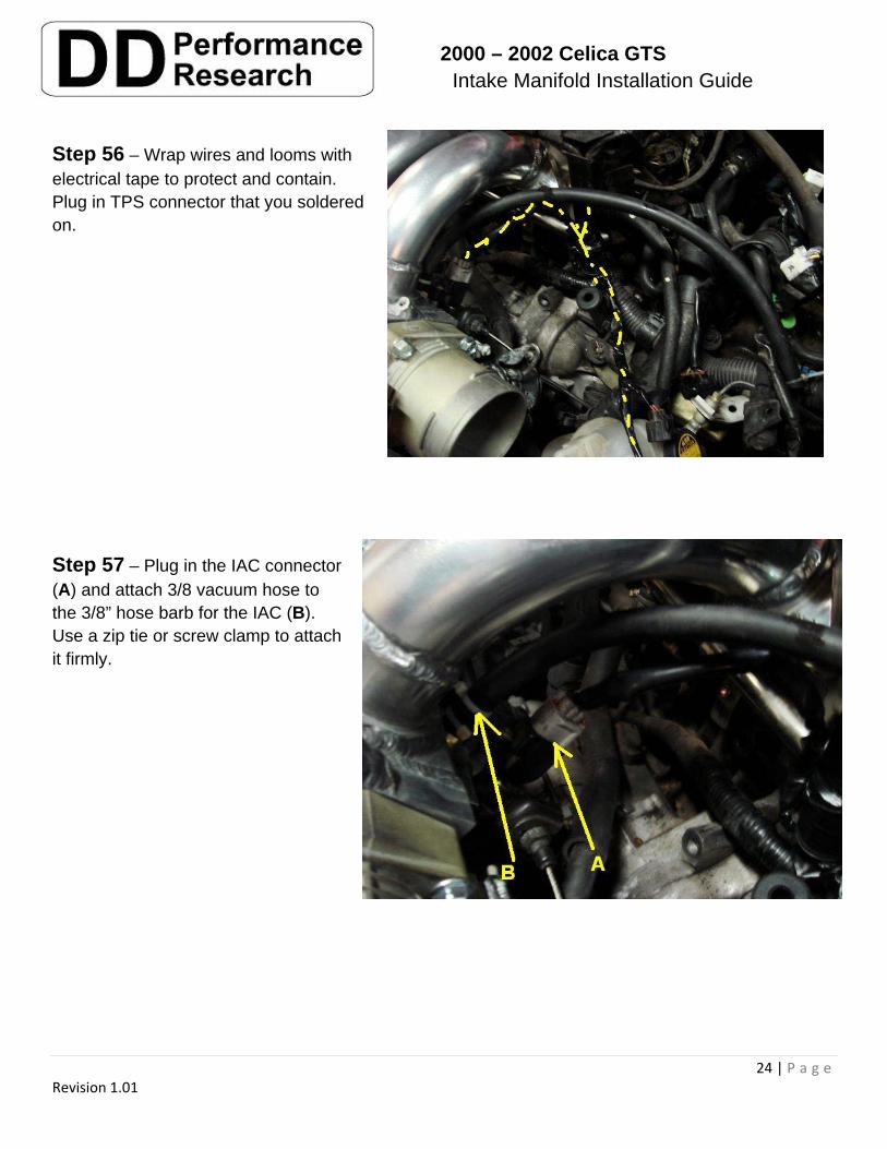
Step 56 – Wrap wires and looms with electrical tape to protect and contain. Plug in TPS connector that you soldered on.
Step 57 – Plug in the IAC connector (A) and attach 3/8 vacuum hose to the 3/8” hose barb for the IAC (B). Use a zip tie or screw clamp to attach it firmly.
2000 – 2002 Celica GTS Intake Manifold Installation Guide
25 | P a g e Revision 1.01
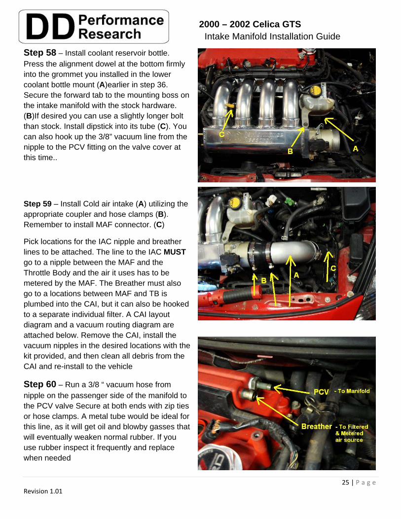
Step 58 – Install coolant reservoir bottle. Press the alignment dowel at the bottom firmly into the grommet you installed in the lower coolant bottle mount (A)earlier in step 36. Secure the forward tab to the mounting boss on the intake manifold with the stock hardware. (B)If desired you can use a slightly longer bolt than stock. Install dipstick into its tube (C). You can also hook up the 3/8” vacuum line from the nipple to the PCV fitting on the valve cover at this time..
Step 59 – Install Cold air intake (A) utilizing the appropriate coupler and hose clamps (B). Remember to install MAF connector. (C)
Pick locations for the IAC nipple and breather lines to be attached. The line to the IAC MUST go to a nipple between the MAF and the Throttle Body and the air it uses has to be metered by the MAF. The Breather must also go to a locations between MAF and TB is plumbed into the CAI, but it can also be hooked to a separate individual filter. A CAI layout diagram and a vacuum routing diagram are attached below. Remove the CAI, install the vacuum nipples in the desired locations with the kit provided, and then clean all debris from the CAI and re-install to the vehicle
Step 60 – Run a 3/8 “ vacuum hose from nipple on the passenger side of the manifold to the PCV valve Secure at both ends with zip ties or hose clamps. A metal tube would be ideal for this line, as it will get oil and blowby gasses that will eventually weaken normal rubber. If you use rubber inspect it frequently and replace when needed
2000 – 2002 Celica GTS Intake Manifold Installation Guide
26 | P a g e Revision 1.01
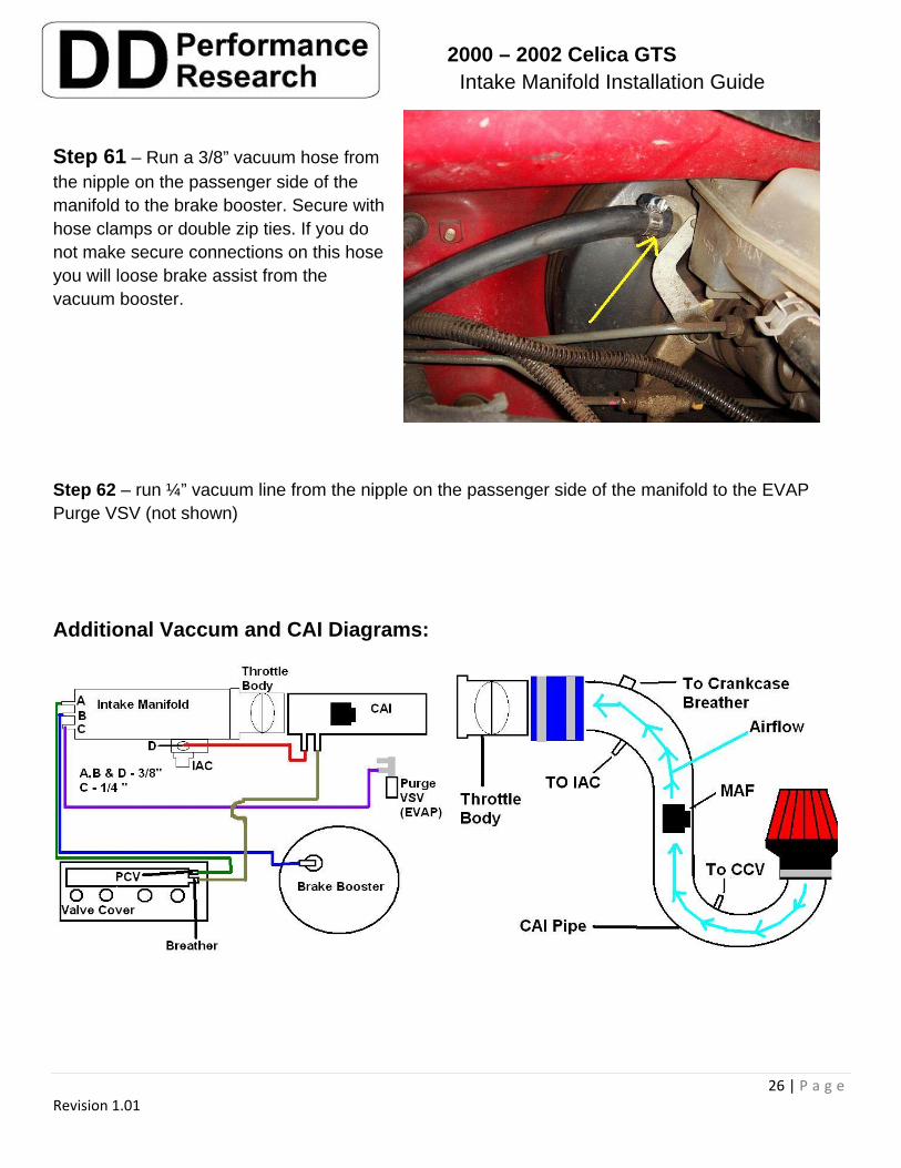
Step 61 – Run a 3/8” vacuum hose from the nipple on the passenger side of the manifold to the brake booster. Secure with hose clamps or double zip ties. If you do not make secure connections on this hose you will loose brake assist from the vacuum booster.
Step 62 – run ¼” vacuum line from the nipple on the passenger side of the manifold to the EVAP Purge VSV (not shown)
Additional Vaccum and CAI Diagrams:
2000 – 2002 Celica GTS Intake Manifold Installation Guide
27 | P a g e Revision 1.01
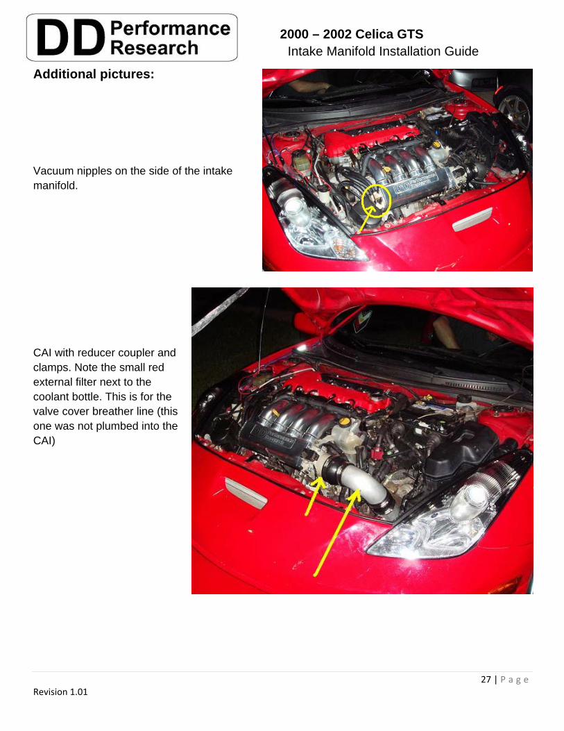
Additional pictures:
Vacuum nipples on the side of the intake manifold.
CAI with reducer coupler and clamps. Note the small red external filter next to the coolant bottle. This is for the valve cover breather line (this one was not plumbed into the CAI)
2000 – 2002 Celica GTS Intake Manifold Installation Guide
28 | P a g e Revision 1.01
Step 63 – Replace ECU mounting box and secure with 3 10mm bolts
Step 64 – Replace ECU and plug in
Step 65 – Replace Battery Tray, Battery, and Battery hold downs,
Step 66 – Replace ECU cover and secure with 2 10mm bolts
Step 67 – Replace Valve Cover Garnish if desired.
Step 68 – Replace positive battery terminal and tighten
Step 69 – Replace Negative battery terminal and tighten
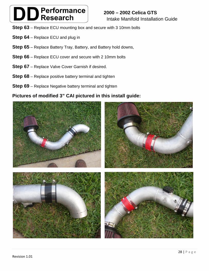
Pictures of modified 3” CAI pictured in this install guide:
2000 – 2002 Celica GTS Intake Manifold Installation Guide
29 | P a g e Revision 1.01
THANK YOU for your purchase!
It is the support of individuals like yourself that makes high quality high performance offerings like this intake manifold possible. If you have any questions or want a copy of a Power FC map for this 3” CAI and 440cc injectors please contact Boosted2.0 or Littlerocket.
Note: You may want to store your old Intake manifold and other stock parts in a clean and sealed heavy plastic bag to keep them clean should you ever decide to sell them or go back to stock for any reason.