Embed Size (px)
Citation preview
Intake Manifold — 5.4L
Removal
WARNING: Do not smoke or carry lighted tobacco or open flame of any type when working on or near any fuel-related components. Highly flammable mixtures are always present and can be ignited. Failure to follow these instructions may result in personal injury.
1. Disconnect the battery ground cable (14301). For additional information, refer to Section 414-01.
2. Relieve the fuel system pressure. For additional information, refer to Section 310-00A(Gasoline), Section 310-00B (NGV) or Section 310-00C (Bi-Fuel).
3. Drain the engine cooling system. For additional information, refer to Section 303-03A.
4. Remove the engine air cleaner (ACL)(9600) and the air cleaner outlet tube (9B659). For additional information, refer to Section 303-12.
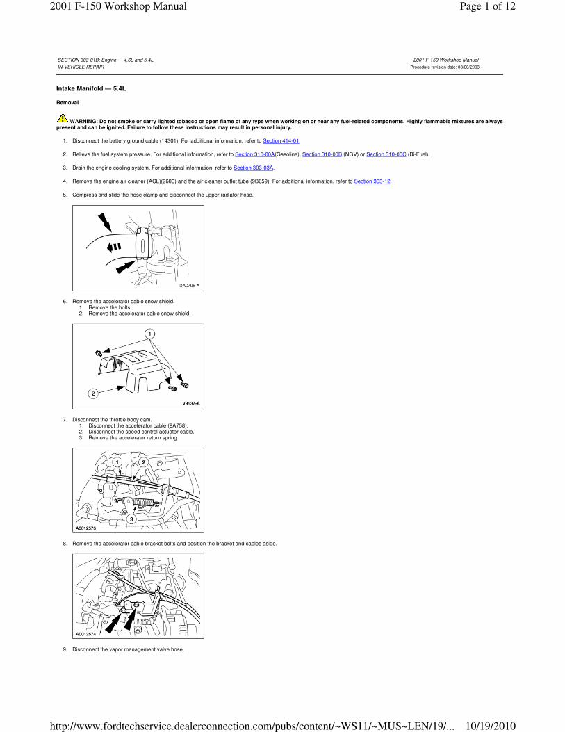
5. Compress and slide the hose clamp and disconnect the upper radiator hose.
6. Remove the accelerator cable snow shield. 1. Remove the bolts. 2. Remove the accelerator cable snow shield.
7. Disconnect the throttle body cam. 1. Disconnect the accelerator cable (9A758). 2. Disconnect the speed control actuator cable. 3. Remove the accelerator return spring.
8. Remove the accelerator cable bracket bolts and position the bracket and cables aside.
9. Disconnect the vapor management valve hose.
SECTION 303-01B: Engine — 4.6L and 5.4L 2001 F-150 Workshop Manual
IN-VEHICLE REPAIR Procedure revision date: 08/06/2003
Page 1 of 122001 F-150 Workshop Manual
10/19/2010http://www.fordtechservice.dealerconnection.com/pubs/content/~WS11/~MUS~LEN/19/...
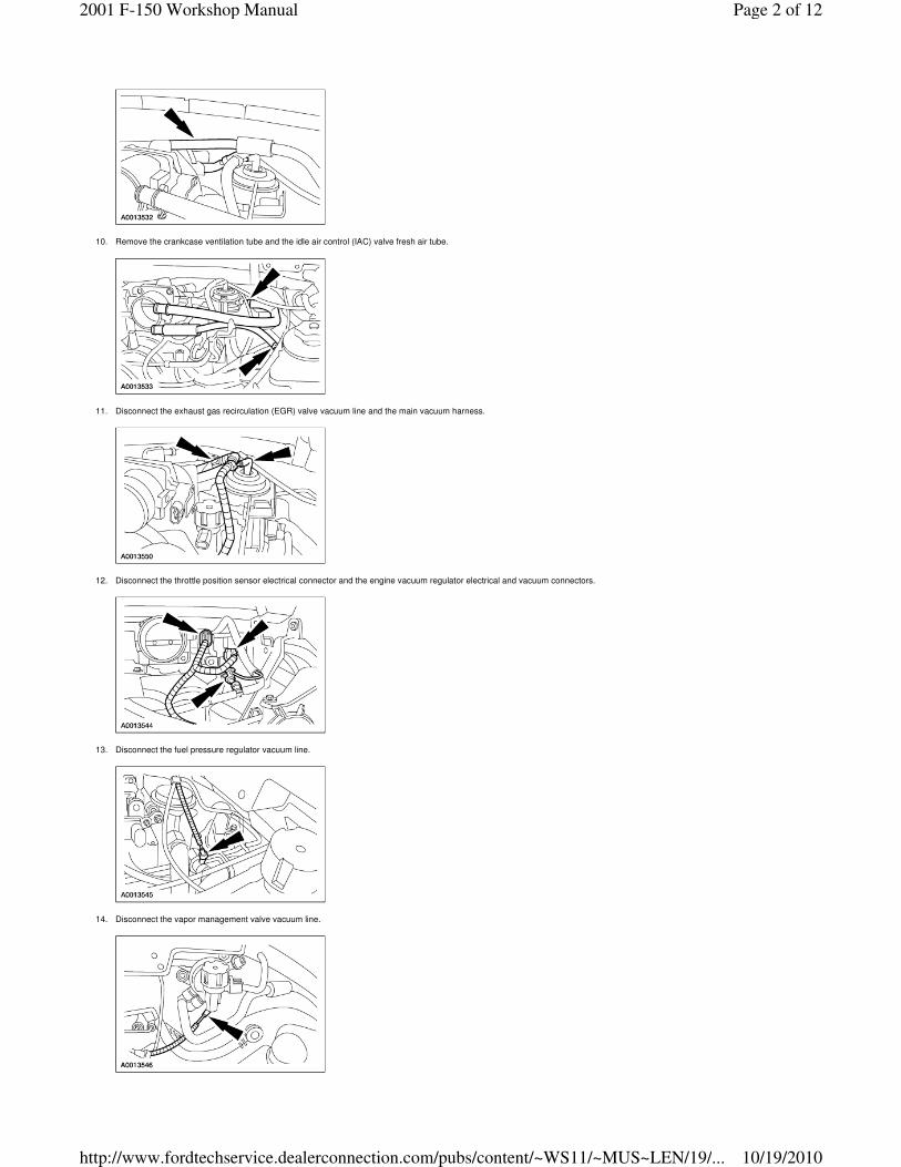
10. Remove the crankcase ventilation tube and the idle air control (IAC) valve fresh air tube.
11. Disconnect the exhaust gas recirculation (EGR) valve vacuum line and the main vacuum harness.
12. Disconnect the throttle position sensor electrical connector and the engine vacuum regulator electrical and vacuum connectors.
13. Disconnect the fuel pressure regulator vacuum line.
14. Disconnect the vapor management valve vacuum line.
Page 2 of 122001 F-150 Workshop Manual
10/19/2010http://www.fordtechservice.dealerconnection.com/pubs/content/~WS11/~MUS~LEN/19/...
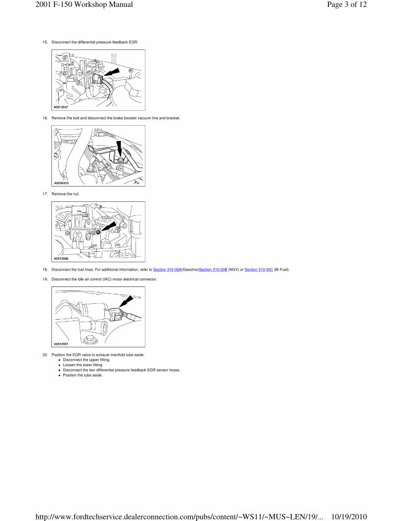
15. Disconnect the differential pressure feedback EGR.
16. Remove the bolt and disconnect the brake booster vacuum line and bracket.
17. Remove the nut.
18. Disconnect the fuel lines. For additional information, refer to Section 310-00A(Gasoline)Section 310-00B (NGV) or Section 310-00C (Bi-Fuel).
19. Disconnect the idle air control (IAC) motor electrical connector.
20. Position the EGR valve to exhaust manifold tube aside.
� Disconnect the upper fitting.
� Loosen the lower fitting.
� Disconnect the two differential pressure feedback EGR sensor hoses.
� Position the tube aside.
Page 3 of 122001 F-150 Workshop Manual
10/19/2010http://www.fordtechservice.dealerconnection.com/pubs/content/~WS11/~MUS~LEN/19/...
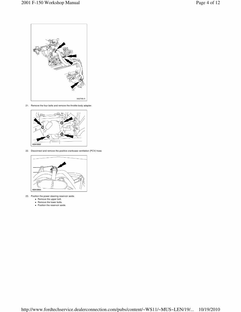
21. Remove the four bolts and remove the throttle body adapter.
22. Disconnect and remove the positive crankcase ventilation (PCV) hose.
23. Position the power steering reservoir aside.
� Remove the upper bolt.
� Remove the lower bolts.
� Position the reservoir aside.
Page 4 of 122001 F-150 Workshop Manual
10/19/2010http://www.fordtechservice.dealerconnection.com/pubs/content/~WS11/~MUS~LEN/19/...
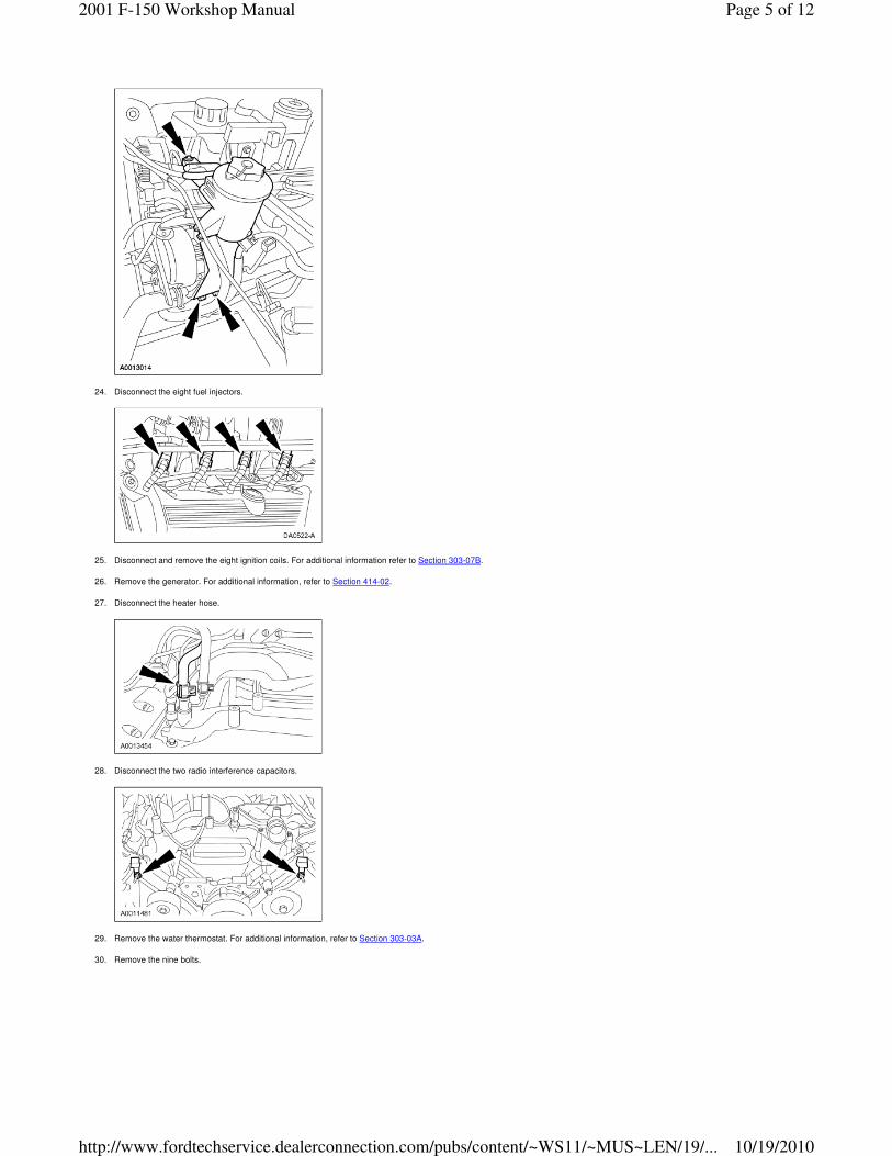
24. Disconnect the eight fuel injectors.
25. Disconnect and remove the eight ignition coils. For additional information refer to Section 303-07B.
26. Remove the generator. For additional information, refer to Section 414-02.
27. Disconnect the heater hose.
28. Disconnect the two radio interference capacitors.
29. Remove the water thermostat. For additional information, refer to Section 303-03A.
30. Remove the nine bolts.
Page 5 of 122001 F-150 Workshop Manual
10/19/2010http://www.fordtechservice.dealerconnection.com/pubs/content/~WS11/~MUS~LEN/19/...
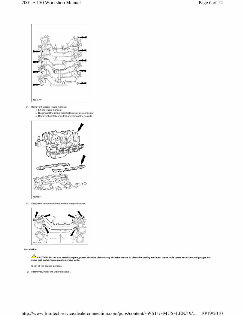
31. Remove the upper intake manifold.
� Lift the intake manifold.
� Disconnect the intake manifold tuning valve connector.
� Remove the intake manifold and discard the gaskets.
32. If required, remove the bolts and the water crossover.
Installation
1. CAUTION: Do not use metal scrapers, power abrasive discs or any abrasive means to clean the sealing surfaces, these tools cause scratches and gouges that make leak paths. Use a plastic scraper only.
Clean all the sealing surfaces.
2. If removed, install the water crossover.
Page 6 of 122001 F-150 Workshop Manual
10/19/2010http://www.fordtechservice.dealerconnection.com/pubs/content/~WS11/~MUS~LEN/19/...
3. Install the intake manifold.
� Position the new intake manifold gaskets.
� Position the upper intake manifold.
� Loosely install nine bolts.
4. NOTE: The thermostat housing bolts are tightened in sequence with the intake manifold bolts. Do not tighten the thermostat housing bolts during thermostat installation.
Install the water thermostat. For additional information, refer to Section 303-03A.
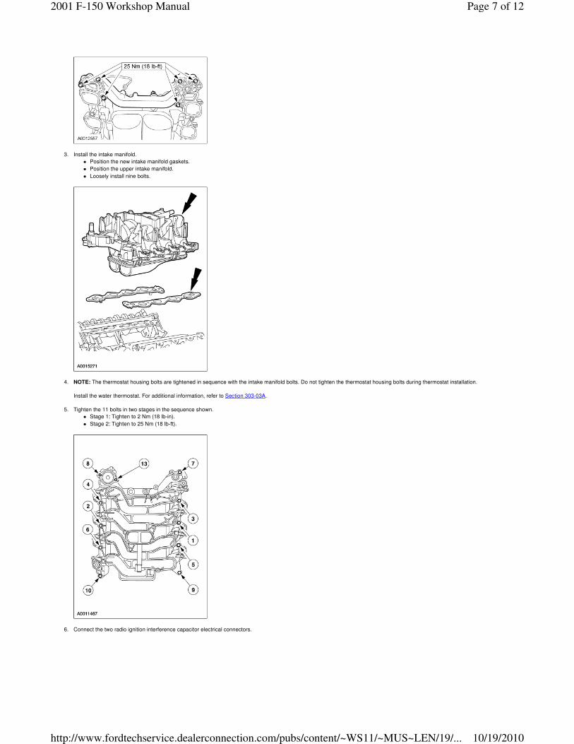
5. Tighten the 11 bolts in two stages in the sequence shown.
� Stage 1: Tighten to 2 Nm (18 lb-in).
� Stage 2: Tighten to 25 Nm (18 lb-ft).
6. Connect the two radio ignition interference capacitor electrical connectors.
Page 7 of 122001 F-150 Workshop Manual
10/19/2010http://www.fordtechservice.dealerconnection.com/pubs/content/~WS11/~MUS~LEN/19/...
7. Connect the heater hose.
8. Install the generator. For additional information, refer to Section 414-02.
9. Install and connect eight ignition coils. For additional information, refer to Section 303-07B.
10. Connect the eight fuel injector electrical connectors.
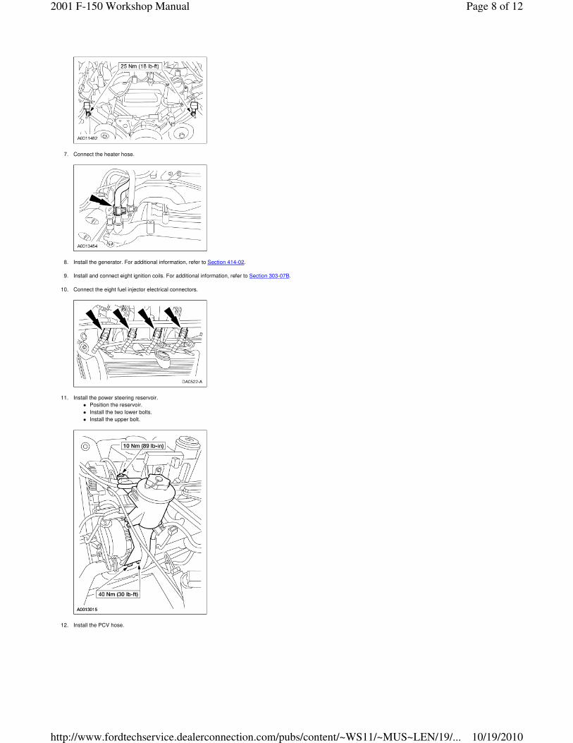
11. Install the power steering reservoir.
� Position the reservoir.
� Install the two lower bolts.
� Install the upper bolt.
12. Install the PCV hose.
Page 8 of 122001 F-150 Workshop Manual
10/19/2010http://www.fordtechservice.dealerconnection.com/pubs/content/~WS11/~MUS~LEN/19/...
13. Install the throttle body adapter and the four bolts. Tighten the bolts in two stages.
� Stage 1: Tighten to 10 Nm 89 (lb-in).
� Stage 2: Tighten an additional 90 degrees.
14. Install the EGR valve to exhaust manifold tube.
� Hand-tighten the fittings.
� Tighten the upper fitting.
� Tighten the lower fitting.
� Connect the two differential pressure feedback EGR sensor hoses.
15. Connect the idle air control motor.
16. Connect the fuel lines. For additional information, refer to Section 310-00A (Gasoline), Section 310-00B (NGV) or Section 310-00C (Bi-Fuel).
17. Install the nut.
Page 9 of 122001 F-150 Workshop Manual
10/19/2010http://www.fordtechservice.dealerconnection.com/pubs/content/~WS11/~MUS~LEN/19/...
18. Connect the brake booster vacuum line and bracket and install the bolt.
19. Connect the differential pressure feedback EGR sensor electrical connector.
20. Connect the vapor management valve vacuum line.
21. Connect the fuel pressure regulator vacuum line.
22. Connect the throttle position sensor connector and the engine vacuum regulator electrical and vacuum connectors.
Page 10 of 122001 F-150 Workshop Manual
10/19/2010http://www.fordtechservice.dealerconnection.com/pubs/content/~WS11/~MUS~LEN/19/...
23. Connect the EGR valve the main vacuum harness vacuum connections.
24. Install the crankcase ventilation tube and the IAC fresh air tube.
25. Connect the vapor management hose.
26. Install the accelerator cable bracket and the bolts.
27. Connect the throttle body cam. 1. Connect the accelerator cable. 2. Connect the speed control actuator cable. 3. Install the throttle return spring.
Page 11 of 122001 F-150 Workshop Manual
10/19/2010http://www.fordtechservice.dealerconnection.com/pubs/content/~WS11/~MUS~LEN/19/...
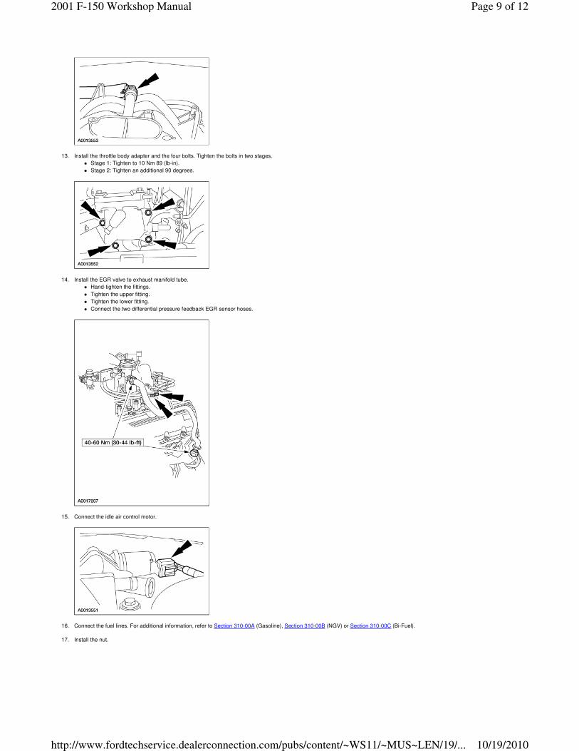
28. Install the accelerator cable snow shield and the bolts.
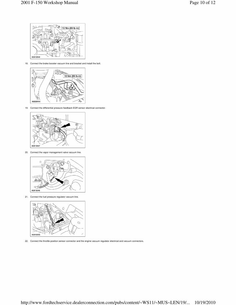
29. Connect the upper radiator hose and position the clamp.
30. Install the engine air cleaner and the air cleaner outlet tube. For additional information, refer to Section 303-12.
31. Connect the battery ground cable. For additional information, refer to Section 414-01.
32. Fill and bleed the engine cooling system. For additional information, refer to Section 303-03A.
Page 12 of 122001 F-150 Workshop Manual
10/19/2010http://www.fordtechservice.dealerconnection.com/pubs/content/~WS11/~MUS~LEN/19/...