Embed Size (px)
Citation preview
Insu
latio
n Sys
tem
s Cat
alog
FO
R COM
MERC
IAL B
UILD
INGS

INSULATION SYSTEMS FOR COMMERCIAL BUILDINGS PAGE 1
PRODUCT OVERVIEW Page 2
FIBERGLAS™ INSULATIONECOTOUCH® THERMAL BATT INSULATIONFlexible fiberglass insulation batts for a wide range of wall and roof/ceiling applications are available unfaced or faced with kraft or foil vapor retarders in thicknesses from 31/2" to 12" and R-values from 11 to 38.
Page 4
ECOTOUCH® FLAME SPREAD 25/FLAME SPREAD 25 EXTENDED FLANGESA light-density, flexible batt insulation for use in walls, ceilings and floors where insulation will be left exposed or where a low flame spread FSK or PSK vapor retarder is needed. R-values range from 11 to 30.
Page 5
SOUND ATTENUATION BATT INSULATIONLightweight, flexible glass fiber insulation batts in standard metal framing widths and thicknesses from 21/2" to 31/2". Sound Attenuation Batts are designed to control noise in interior partitions.
Page 6
SONOBATTS® INSULATIONFlexible, glass fiber insulation batts with R-values from 11 to 38 for economical noise control and thermal performance in ceiling systems.
Page 8
CURTAINWALL INSULATIONDesigned to provide excellent thermal properties in curtainwall spandrel systems, Curtainwall Insulation/CW 225 is a semirigid fiberglass insulation available unfaced or with an FSK facing in thicknesses from 1" to 4".
Page 9
FIBERGLAS™ 700 SERIES INSULATIONFlexible, semirigid and rigid rectangular boards of varying densities and thicknesses or unfaced with FSK or ASJ facings. Each series has thermal, acoustical and physical properties which suit them to a variety of specific construction applications.
Page 10
FOAMULAR® EXTRUDED POLYSTYRENE (XPS) INSULATIONExtruded polystyrene rigid foam insulation with stable, high insulating values and excellent moisture resistance. An integral skin and the closed-cell nature of the material eliminate the need for facers.
Page 12
ELAMINATOR® METAL BUILDING INSULATION SYSTEMThe ELAMINATOR® Insulation System installs ELAMINATOR® Insulation with patented machines on metal building roofs with 300 Series machines providing safety solutions for fall protection.
Page 14
CERTIFIED R METAL BUILDING INSULATIONCertified R Metal Building Insulation is laminated with specified facings to provide insulation for metal building walls and roofs.
Page 15
APPLICATION RECOMMENDATIONSInstalling insulation for thermal and acoustical performance, health aspects and applicable standards.
Page 16
ENVIRONMENTAL AND SUSTAINABILITY Page 21
ATTACHMENT SYSTEMS Page 22
GUIDE SPECIFICATIONS Page 23
INDUSTRY STANDARDS Page 24
TABLE OF CONTENTSINSULATION SYSTEMS FOR COMMERCIAL BUILDINGS
PAGE 2 1-800-GET-PINK® www.owenscorning.com
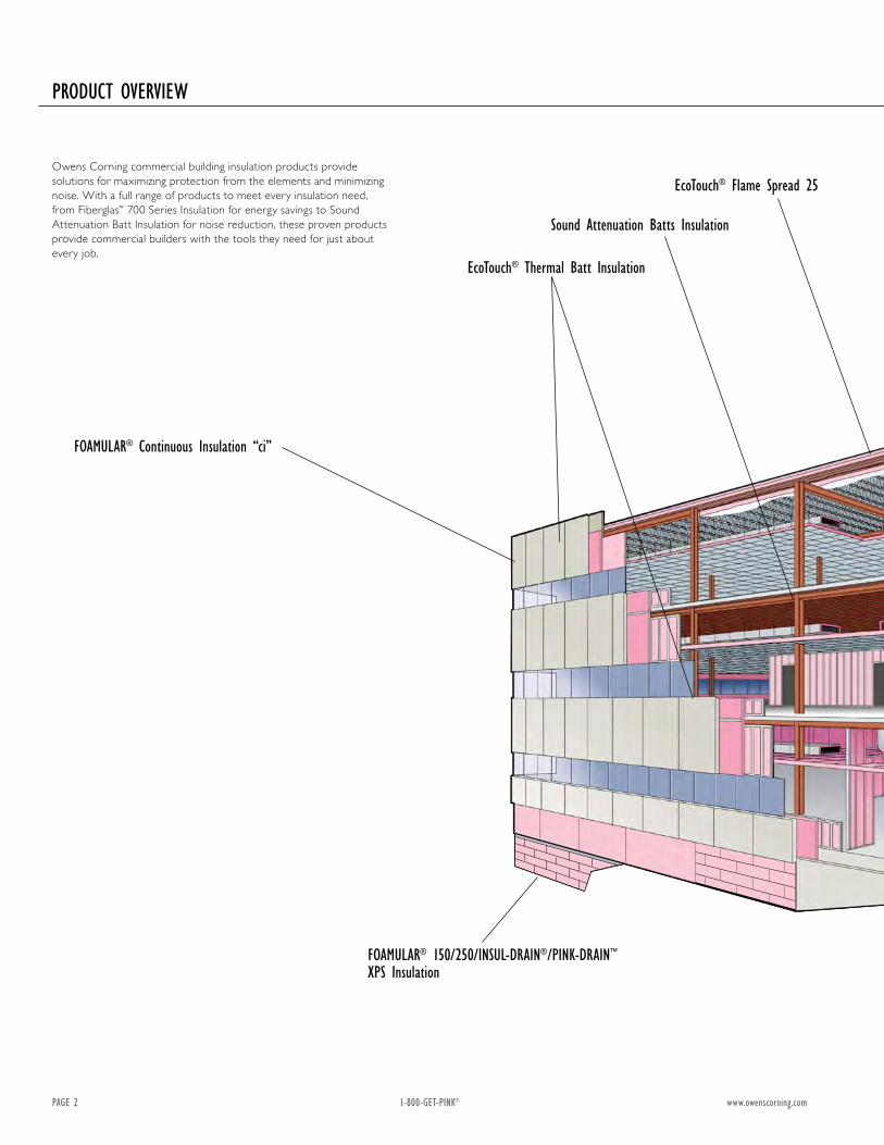
PRODUCT OVERVIEW
FOAMULAR® Continuous Insulation “ci”
Sound Attenuation Batts Insulation
EcoTouch® Flame Spread 25
EcoTouch® Thermal Batt Insulation
FOAMULAR® 150/250/INSUL-DRAIN®/PINK-DRAIN™ XPS Insulation
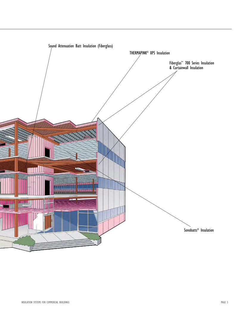
Owens Corning commercial building insulation products provide solutions for maximizing protection from the elements and minimizing noise. With a full range of products to meet every insulation need, from Fiberglas™ 700 Series Insulation for energy savings to Sound Attenuation Batt Insulation for noise reduction, these proven products provide commercial builders with the tools they need for just about every job.
INSULATION SYSTEMS FOR COMMERCIAL BUILDINGS PAGE 3
PRODUCT OVERVIEW
THERMAPINK® XPS Insulation
Fiberglas™ 700 Series Insulation & Curtainwall Insulation
Sonobatts® Insulation
Sound Attenuation Batt Insulation (Fiberglass)

PAGE 4 1-800-GET-PINK® www.owenscorning.com
ECOTOUCH® THERMAL BATT INSULATIONFIBERGLASS INSULATION–PRODUCT DATA
DESCRIPTION & USES• Unfaced
• Kraft-Faced
• Foil-Faced
• For roof/ceiling and interior/exterior wall applications; installed in wood or metal framing cavities or between furring channels.
• Flexible fiberglass insulation 31/2" to 12" thick available unfaced, foil-faced or kraft-faced.
FEATURES & BENEFITS• Sized for metal or wood framing; can be stapled
or friction-fit. Easy to handle and install. Trim and fabricate with a utility knife.
• Meets thermal specifications.
• Improves interior noise control.
• Inorganic. Non-corrosive to steel, aluminum or copper.
• Dimensionally stable and will not decay or slump in the cavity.
• SpaceSaver packaging reduces freight and streamlines handling.
DESIGN CONSIDERATIONS• In commercial roof/ceiling thermal applications,
the building envelope must block air movement. Do not rely on the insulation or facing to provide an air barrier.
• Adding insulation inside a structure’s perimeter exposes the exterior building materials to greater temperature extremes and expansion and contraction forces.
• Equip curtainwall buildings with sprinkler systems for fire protection as required by building codes.
• Luminaire performance may be affected by closely placed insulation. The National Electric Code requires: Unless fixtures are approved for such use, do not install insulation on top of or within 3" of recessed light fixtures.
• Evaluate the use of vapor retarders based on the project’s unique requirements. Maintain facing integrity for vapor retarder performance.
• Kraft facings on this insulation will burn and must not be left exposed. Facings should be installed in substantial contact with approved ceiling, wall or floor material.
APPLICABLE STANDARDS• Surface burning characteristics comply with ASTM
E84, a standard used to measure and describe properties of products in response to heat and flame under laboratory conditions. The results are not intended to reflect hazards presented under actual fire conditions. Base material is classified as noncombustible when tested per ASTM E136.
• See tables for data and other applicable standards.
ECOTOUCH® THERMAL BATT INSULATION TECHNICAL DATA/WALL OR CEILINGWIDTH LENGTH THICKNESS R-VALUE1
METAL FRAME CONSTRUCTION
16" 406 mm 24" 609 mm 48" 1219 mm 96" 2,438 mm 31⁄2" 89 mm 11.016" 406 mm 24" 609 mm 48" 1219 mm 96" 2438 mm 31⁄2" 89 mm 13.016" 406 mm 24" 609 mm 48" 1219 mm 96" 2438 mm 61⁄4" 159 mm 19.0
WOOD FRAME CONSTRUCTION
15" 381 mm 19.25" 489 mm 23" 584 mm 93" 2362 mm 105" 2667 mm 31⁄2" 89 mm 11.011" 279 mm 15" 381 mm 19.25" 489 mm 23" 584 mm 93" 2362 mm 105" 2667 mm 31⁄2" 89 mm 13.0
15" 381 mm 23" 584 mm 93" 2362 mm 105" 2667 mm 31⁄2" 89 mm 15.011" 279 mm 15" 381 mm 19.25" 489 mm 23" 584 mm 48" 1219 mm 93" 2362 mm 105" 2667 mm 61⁄4" 159 mm 19.0
15" 381 mm 23" 584 mm 93" 2362 mm 51⁄2" 139 mm 21.0ROOF/CEILING CONSTRUCTION11" 279 mm 15" 381 mm 23" 584 mm 48" 1219 mm 93" 2362 mm 61⁄4" 159 mm 19.0
16" 406 mm 19.25" 489 mm 24" 609 mm 48" 1219 mm 96" 2438 mm 61⁄4" 159 mm 19.015" 381 mm 19.25" 489 mm 23" 584 mm 48" 1219 mm 63⁄4" 171 mm 22.015" 381 mm 23" 584 mm 48" 1219 mm 96" 2438 mm 8" 203 mm 25.016" 406 mm 19.25" 489 mm 24" 609 mm 96" 2438 mm 8" 203 mm 25.015" 381 mm 23" 584 mm 48" 1219 mm 91⁄2" 241 mm 30.0
12" 305 mm 16" 406 mm 19.25" 489 mm 24" 609 mm 48" 1219 mm 91⁄2" 241 mm 30.015.5" 394 mm 23.75" 603 mm 48" 1219 mm 81⁄4" 209 mm 30.0 C2
12" 305 mm 16" 406 mm 24" 609 mm 48" 1219 mm 12" 305 mm 38.015.5" 394 mm 23.75" 603 mm 48" 1219 mm 101⁄4" 260 mm 38.0 C2
1. R-values differ. Find out why in the seller’s fact sheet. Higher R-values mean greater insulating power.2. C = Cathedral ceilings. Unfaced EcoTouch® Thermal Batt Insulation complies with the property requirements of ASTM C665, Type I
and ASTM E 136. Kraft-Faced Thermal Batt Insulation complies with ASTM C665, Type II and Class C. Check for availability in your service area. Foil-Faced EcoTouch® Thermal Batt Insulation complies with ASTM C665, Type III, Class B and C.
SURFACE BURNING CHARACTERISTICS/BUILDING CODE CONSTRUCTION CLASSIFICATIONSPRODUCT TYPES FLAME SPREAD SMOKE DEVELOPED ICBO BOCA SBCCI ICCEcoTouch® Unfaced Insulation 10 10 All Types All Types All Types All TypesEcoTouch® Foil-Faced Insulation 75 150 III, IV, V All Types All Types III, IV, VEcoTouch® Kraft-Faced Insulation N/R N/R III, IV, V III, IV, V III, V, VI III, IV, V
EcoTouch® Thermal Batt Insulation complies with the International Building Code (ICC), Uniform Building Code (ICBO), National Building Code (BOCA) and Standard Building Code (SBCCI) model code requirements for building construction types listed above. Kraft and standard foil facing on EcoTouch® Thermal Batt Insulation will burn and must not be left exposed. The facing must be installed in substantial contact with an approved interior partition construction material. Protect facing from open flame or other heat source. Due to the potential for skin irritation, unfaced EcoTouch® Thermal Batt Insulation should not be used for exposed applications where it will be subject to human contact.
VAPOR RETARDERS KRAFT FOILPerms Maximum1 1 0.5WATER VAPOR SORPTIONMaximum by Weight 5%DIMENSIONAL STABILITYLinear Shrinkage Less than 0.1%
1. Products are tested in accordance with: R-value ASTM C518 Surface Burning Characteristics ASTM E84 Perm Rating ASTM E96
PRODUCT 57%
APPLIES TO KRAFT-FACED PRODUCT
PRODUCT 98%
APPLIES TO UNFACED PRODUCT
APPLIES TO FACED PRODUCTAPPLIES TO UNFACED PRODUCT
INSULATION SYSTEMS FOR COMMERCIAL BUILDINGS PAGE 5
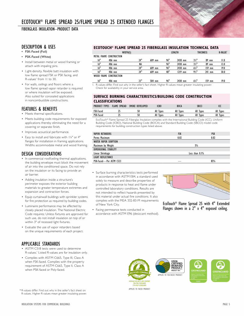
ECOTOUCH® FLAME SPREAD 25/FLAME SPREAD 25 EXTENDED FLANGESFIBERGLASS INSULATION–PRODUCT DATA
DESCRIPTION & USES• FSK-Faced (Foil)
• PSK-Faced (White)
• Install between metal or wood framing or attach with impaling pins.
• Light-density, flexible batt insulation with low flame spread FSK or PSK facing, and R-values* from 11 to 30.
• For walls, ceilings and floors where a low flame spread vapor retarder is required or where insulation will be exposed. Also suited for concealed applications in noncombustible constructions.
FEATURES & BENEFITS• Meets thermal specifications.
• Meets building code requirements for exposed applications thereby eliminating the need for a covering or separate finish.
• Improves acoustical performance.
• Easy to install and fabricate with 11⁄4" or 4" flanges for installation in framing applications. Widths accommodate metal and wood framing.
DESIGN CONSIDERATIONS• In commercial roof/ceiling thermal applications,
the building envelope must block the movement of air into the conditioned space. Do not rely on the insulation or its facing to provide an air barrier.
• Adding insulation inside a structure’s perimeter exposes the exterior building materials to greater temperature extremes and expansion and contraction forces.
• Equip curtainwall buildings with sprinkler systems for fire protection as required by building codes.
• Luminaire performance may be affected by closely placed insulation. The National Electric Code requires: Unless fixtures are approved for such use, do not install insulation on top of or within 3" of recessed light fixtures.
• Evaluate the use of vapor retarders based on the unique requirements of each project.
APPLICABLE STANDARDS• ASTM C518 tests were used to determine
R-values.* Listed R-values are for insulation only.
• Complies with ASTM C665, Type III, Class A when FSK-faced. Complies with the property requirement of ASTM C665, Type II, Class A when PSK-faced or Poly-faced.
• Surface burning characteristics tests performed in accordance with ASTM E84, a standard used solely to measure and describe properties of products in response to heat and flame under controlled laboratory conditions. Results are not intended to reflect hazards presented by this material under actual fire conditions. It also complies with the MEA 332-83-M requirements of New York City.
• Facing permeance tests conducted in accordance with ASTM E96 (desiccant method).
* R-values differ. Find out why in the seller's fact sheet on R-values. Higher R-values mean greater insulating power.
EcoTouch® Flame Spread 25 with 4" Extended Flanges shown in a 2" x 4" exposed ceiling.
ECOTOUCH® FLAME SPREAD 25 FIBERGLASS INSULATION TECHNICAL DATAWIDTH(S) LENGTH THICKNESS R-VALUE1
METAL FRAME CONSTRUCTION16" 406 mm 24" 609 mm 96" 2438 mm 31⁄2" 89 mm 11.016" 406 mm NA 96" 2438 mm 31⁄2" 89 mm 13.016" 406 mm 24" 609 mm 96" 2438 mm 61⁄4" 159 mm 19.016" 406 mm 24" 609 mm 48" 1219 mm 91⁄2" 241 mm 30.0
WOOD FRAME CONSTRUCTION
16" 406 mm 23" 584 mm 96" 2438 mm 61⁄4" 159 mm 19.01. R-values differ. Find out why in the seller’s fact sheet. Higher R-values mean greater insulating power.
Check for availability in your service area.
SURFACE BURNING CHARACTERISTICS/BUILDING CODE CONSTRUCTION CLASSIFICATIONSPRODUCT TYPES FLAME SPREAD SMOKE DEVELOPED ICBO BOCA SBCCI ICC
FSK-Faced 25 50 All Types All Types All Types All TypesPSK-Faced 25 50 All Types All Types All Types All Types
EcoTouch® Flame Spread 25 Fiberglas Insulation complies with the International Building Code (ICC), Uniform Building Code (ICBO), National Building Code (BOCA) and Standard Building Code (SBCCI) model code requirements for building construction types listed above.
VAPOR RETARDERS FSK PSKPerms Maximum 0.02 0.02WATER VAPOR SORPTIONMaximum by Weight 5%DIMENSIONAL STABILITYLinear Shrinkage Less than 0.1%LIGHT REFLECTANCEPSK-Faced—Per ASTM C523 — 85%
PRODUCT 78%
APPLIES TO FSK-FACED PRODUCT
APPLIES TO FACED PRODUCT
PAGE 6 1-800-GET-PINK® www.owenscorning.com
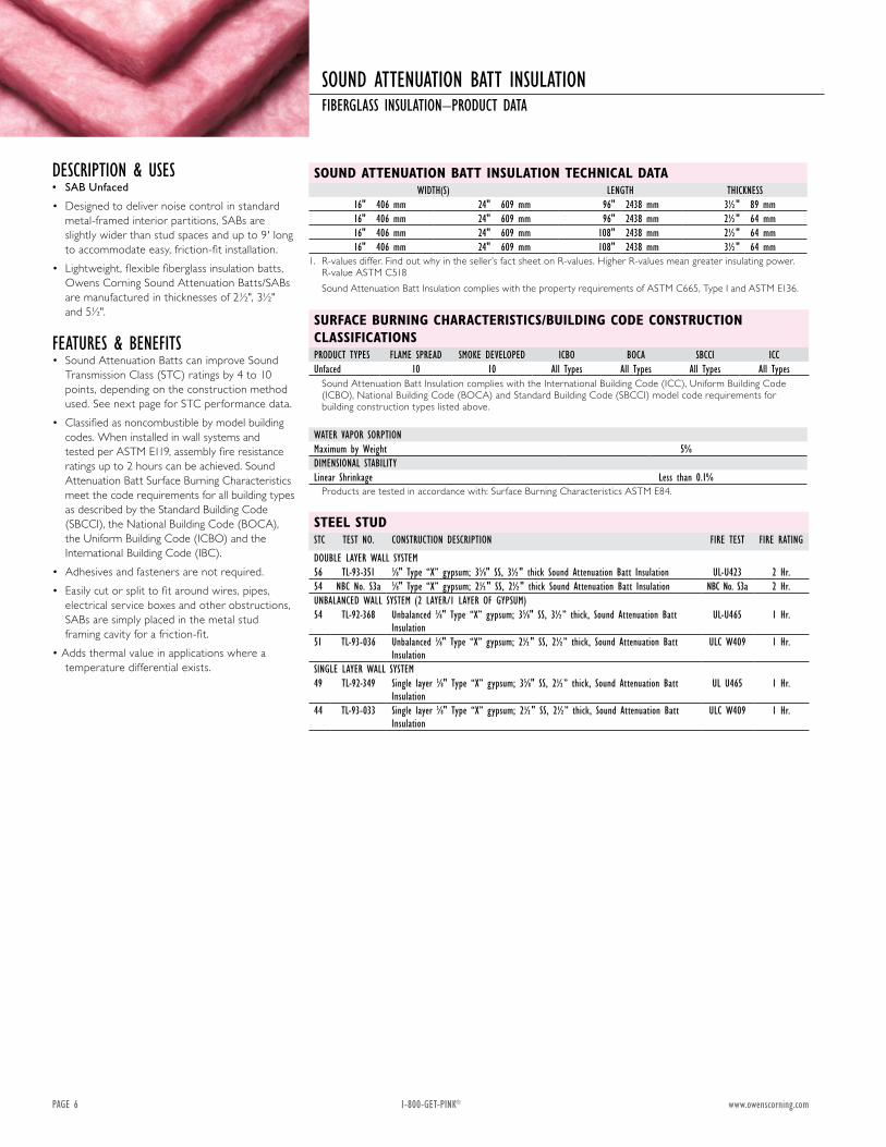
SOUND ATTENUATION BATT INSULATIONFIBERGLASS INSULATION–PRODUCT DATA
DESCRIPTION & USES• SAB Unfaced
• Designed to deliver noise control in standard metal-framed interior partitions, SABs are slightly wider than stud spaces and up to 9' long to accommodate easy, friction-fit installation.
• Lightweight, flexible fiberglass insulation batts, Owens Corning Sound Attenuation Batts/SABs are manufactured in thicknesses of 21/2", 31/2" and 51/2".
FEATURES & BENEFITS• Sound Attenuation Batts can improve Sound
Transmission Class (STC) ratings by 4 to 10 points, depending on the construction method used. See next page for STC performance data.
• Classified as noncombustible by model building codes. When installed in wall systems and tested per ASTM E119, assembly fire resistance ratings up to 2 hours can be achieved. Sound Attenuation Batt Surface Burning Characteristics meet the code requirements for all building types as described by the Standard Building Code (SBCCI), the National Building Code (BOCA), the Uniform Building Code (ICBO) and the International Building Code (IBC).
• Adhesives and fasteners are not required.
• Easily cut or split to fit around wires, pipes, electrical service boxes and other obstructions, SABs are simply placed in the metal stud framing cavity for a friction-fit.
• Adds thermal value in applications where a temperature differential exists.
SOUND ATTENUATION BATT INSULATION TECHNICAL DATAWIDTH(S) LENGTH THICKNESS
16" 406 mm 24" 609 mm 96" 2438 mm 31⁄2" 89 mm16" 406 mm 24" 609 mm 96" 2438 mm 21⁄2" 64 mm16" 406 mm 24" 609 mm 108" 2438 mm 21⁄2" 64 mm16" 406 mm 24" 609 mm 108" 2438 mm 31⁄2" 64 mm
1. R-values differ. Find out why in the seller’s fact sheet on R-values. Higher R-values mean greater insulating power. R-value ASTM C518
Sound Attenuation Batt Insulation complies with the property requirements of ASTM C665, Type I and ASTM E136.
SURFACE BURNING CHARACTERISTICS/BUILDING CODE CONSTRUCTION CLASSIFICATIONSPRODUCT TYPES FLAME SPREAD SMOKE DEVELOPED ICBO BOCA SBCCI ICCUnfaced 10 10 All Types All Types All Types All Types
Sound Attenuation Batt Insulation complies with the International Building Code (ICC), Uniform Building Code (ICBO), National Building Code (BOCA) and Standard Building Code (SBCCI) model code requirements for building construction types listed above.
WATER VAPOR SORPTIONMaximum by Weight 5%DIMENSIONAL STABILITYLinear Shrinkage Less than 0.1%
Products are tested in accordance with: Surface Burning Characteristics ASTM E84.
STEEL STUDSTC TEST NO. CONSTRUCTION DESCRIPTION FIRE TEST FIRE RATING
DOUBLE LAYER WALL SYSTEM56 TL-93-351 5⁄8" Type “X” gypsum; 35⁄8" SS, 31⁄2" thick Sound Attenuation Batt Insulation UL-U423 2 Hr.54 NBC No. S3a 5⁄8" Type “X” gypsum; 21⁄2" SS, 21⁄2" thick Sound Attenuation Batt Insulation NBC No. S3a 2 Hr.UNBALANCED WALL SYSTEM (2 LAYER/1 LAYER OF GYPSUM)54 TL-92-368 Unbalanced 5⁄8" Type “X” gypsum; 35⁄8" SS, 31⁄2” thick, Sound Attenuation Batt
InsulationUL-U465 1 Hr.
51 TL-93-036 Unbalanced 5⁄8" Type “X” gypsum; 21⁄2" SS, 21⁄2” thick, Sound Attenuation Batt Insulation
ULC W409 1 Hr.
SINGLE LAYER WALL SYSTEM49 TL-92-349 Single layer 5⁄8" Type “X” gypsum; 35⁄8" SS, 21⁄2” thick, Sound Attenuation Batt
InsulationUL U465 1 Hr.
44 TL-93-033 Single layer 5⁄8" Type “X” gypsum; 21⁄2" SS, 21⁄2” thick, Sound Attenuation Batt Insulation
ULC W409 1 Hr.
INSULATION SYSTEMS FOR COMMERCIAL BUILDINGS PAGE 7
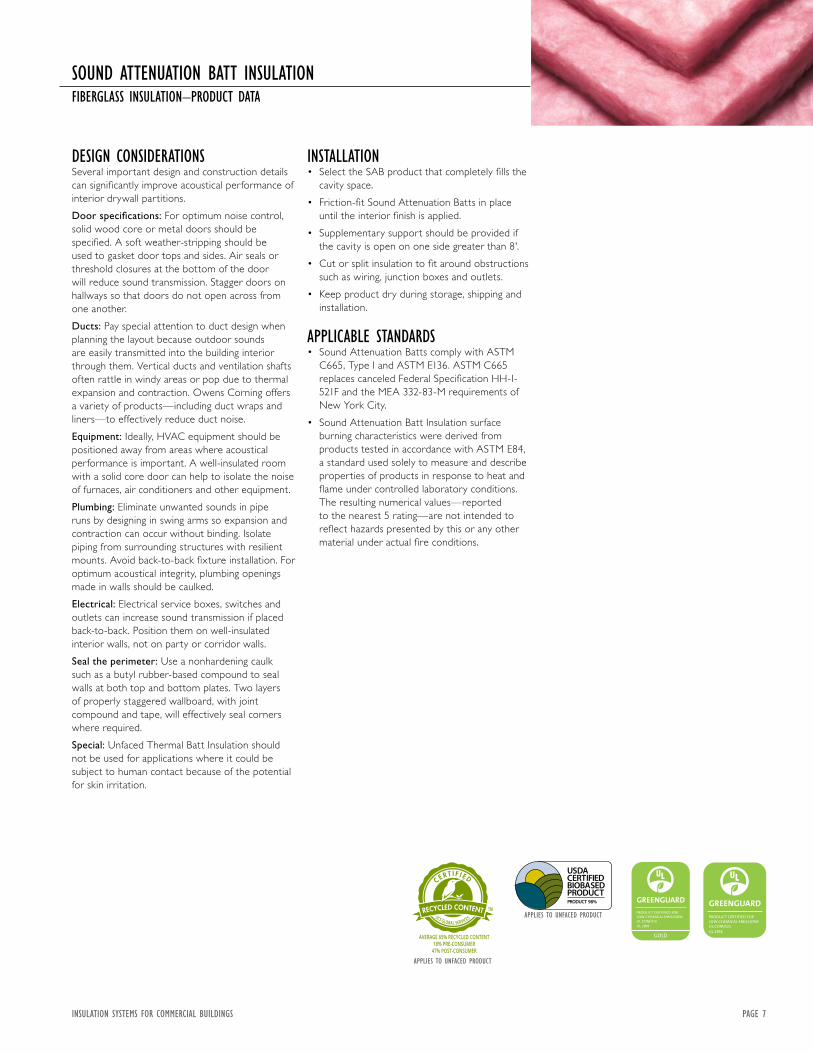
SOUND ATTENUATION BATT INSULATIONFIBERGLASS INSULATION–PRODUCT DATA
DESIGN CONSIDERATIONSSeveral important design and construction details can significantly improve acoustical performance of interior drywall partitions.
Door specifications: For optimum noise control, solid wood core or metal doors should be specified. A soft weather-stripping should be used to gasket door tops and sides. Air seals or threshold closures at the bottom of the door will reduce sound transmission. Stagger doors on hallways so that doors do not open across from one another.
Ducts: Pay special attention to duct design when planning the layout because outdoor sounds are easily transmitted into the building interior through them. Vertical ducts and ventilation shafts often rattle in windy areas or pop due to thermal expansion and contraction. Owens Corning offers a variety of products—including duct wraps and liners—to effectively reduce duct noise.
Equipment: Ideally, HVAC equipment should be positioned away from areas where acoustical performance is important. A well-insulated room with a solid core door can help to isolate the noise of furnaces, air conditioners and other equipment.
Plumbing: Eliminate unwanted sounds in pipe runs by designing in swing arms so expansion and contraction can occur without binding. Isolate piping from surrounding structures with resilient mounts. Avoid back-to-back fixture installation. For optimum acoustical integrity, plumbing openings made in walls should be caulked.
Electrical: Electrical service boxes, switches and outlets can increase sound transmission if placed back-to-back. Position them on well-insulated interior walls, not on party or corridor walls.
Seal the perimeter: Use a nonhardening caulk such as a butyl rubber-based compound to seal walls at both top and bottom plates. Two layers of properly staggered wallboard, with joint compound and tape, will effectively seal corners where required.
Special: Unfaced Thermal Batt Insulation should not be used for applications where it could be subject to human contact because of the potential for skin irritation.
INSTALLATION• Select the SAB product that completely fills the
cavity space.
• Friction-fit Sound Attenuation Batts in place until the interior finish is applied.
• Supplementary support should be provided if the cavity is open on one side greater than 8'.
• Cut or split insulation to fit around obstructions such as wiring, junction boxes and outlets.
• Keep product dry during storage, shipping and installation.
APPLICABLE STANDARDS• Sound Attenuation Batts comply with ASTM
C665, Type I and ASTM E136. ASTM C665 replaces canceled Federal Specification HH-I-521F and the MEA 332-83-M requirements of New York City.
• Sound Attenuation Batt Insulation surface burning characteristics were derived from products tested in accordance with ASTM E84, a standard used solely to measure and describe properties of products in response to heat and flame under controlled laboratory conditions. The resulting numerical values—reported to the nearest 5 rating—are not intended to reflect hazards presented by this or any other material under actual fire conditions.
PRODUCT 98%
APPLIES TO UNFACED PRODUCT
APPLIES TO UNFACED PRODUCT
PAGE 8 1-800-GET-PINK® www.owenscorning.com
SONOBATTS® INSULATIONFIBERGLASS INSULATION–PRODUCT DATA
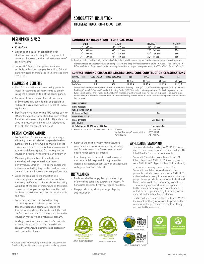
DESCRIPTION & USES• Unfaced
• Kraft-Faced
• Designed and sized for application over standard suspended ceiling tiles, they control noise and improve the thermal performance of ceiling systems.
• Sonobatts® flexible fiberglass insulation is available in R-values* ranging from 11 to 38 and either unfaced or kraft-faced in thicknesses from 31/2" to 12".
FEATURES & BENEFITS• Ideal for renovation and remodeling projects;
install in suspended ceiling systems by simply laying the product on top of the ceiling panels.
• Because of the excellent thermal resistance of Sonobatts insulation, it may be possible to reduce the size and/or operating cost of HVAC equipment.
• Significantly improves ceiling STC ratings by 4 to 10 points. Sonobatts insulation has been tested for air erosion (according to UL 181) and can be used in a return air plenum at air velocities up to 1,000 fpm for acoustical benefit.
DESIGN CONSIDERATIONS• For Sonobatts® insulation to improve energy
efficiency when installed on suspended ceiling systems, the building envelope must block the movement of air from the outdoor environment to the conditioned space. Do not rely on the insulation or its facing to provide an air barrier.
• Minimizing the number of penetrations in the ceiling will help to maximize thermal performance. Large (4' x 4') ceiling panels and surface-mounted lighting can be used to reduce penetrations and improve thermal performance.
• Using the area above the insulation as a return air plenum would render the insulation thermally ineffective, as the air above the ceiling would be at the same temperature as the room below. In return plenum applications, thermal insulation would best be added at the side walls and roof.
• For acoustical control in floor-to-ceiling partition systems, insulation placed at the top of a suspended ceiling will reduce the transfer of sound over the partition. If thermal performance is not a factor, the area above the insulation may serve as a return air plenum.
• Adding insulation inside a structure’s perimeter exposes the exterior building materials to greater temperature extremes and expansion and contraction forces.
• Refer to the ceiling system manufacturer’s recommendations for maximum backloading and for information on fire-resistance rated floor or roof-ceiling assemblies.
• Kraft facings on this insulation will burn and must not be left exposed. Facing should be installed in substantial contact with an approved ceiling construction material.
INSTALLATION• Easily installed by simply laying them on top
of the ceiling panel and suspension system. Fit Sonobatts together tightly to reduce heat loss.
• Keep product dry during storage, shipping and installation.
APPLICABLE STANDARDS• Tests conducted according to ASTM C18 were
used to determine thermal resistance values. The listed R-values* are for insulation only.
• Sonobatts® insulation complies with ASTM C665, Type I and ASTM E136 (unfaced) and with ASTM C665, Type II, Class C (kraft-faced.)
• The surface burning characteristics for Sonobatts insulation were derived from products tested in accordance with ASTM E84, a standard used solely to measure and describe properties of products in response to heat and flame under controlled laboratory conditions. The resulting numerical values—reported to the nearest 5 rating—are not intended to reflect hazards presented by this or any other material under actual fire conditions.
• Tests conducted in accordance with ASTM E96 (desiccant method) were used to produce the vapor retarder permeance of the kraft facings on Sonobatts insulation.
* R-values differ. Find out why in the seller’s fact sheet on R-values. Higher R-values mean greater insulating power.
SONOBATTS® INSULATION TECHNICAL DATAWIDTH LENGTH THICKNESS R-VALUE(1)
24" 609 mm 48" 1219 mm 12" 305 mm 38.024" 609 mm 48" 1219 mm 91⁄2" 241 mm 30.024" 609 mm 48" 1219 mm 61⁄4" 159 mm 19.024" 609 mm 48" 1219 mm 31⁄2" 89 mm 11.0
1. R-values differ. Find out why in the seller’s fact sheet on R-values. Higher R-values mean greater insulating power.
Note: Unfaced Sonobatts® insulation complies with the property requirements of ASTM C665, Type I and ASTM E136. Kraft-faced Sonobatts® Insulation complies with the property requirements of ASTM C665, Type II, Class C.
SURFACE BURNING CHARACTERISTICS/BUILDING CODE CONSTRUCTION CLASSIFICATIONSPRODUCT TYPES FLAME SPREAD SMOKE DEVELOPED ICBO BOCA SBCCI ICC
Unfaced 10 10 All Types All Types All Types All TypesKraft-Faced N/R N/R III, IV, V III, IV, V III, IV, V III, IV, V
Sonobatts® insulation complies with the International Building Code (ICC), Uniform Building code (ICBO), National Building Code (BOCA) and Standard Building Code (SBCCI) model code requirements for building construction types listed above. Kraft facing on Sonobatts® insulation will burn and must not be left exposed. The facing must be installed in substantial contact with an approved ceiling construction material. Protect facing from open flame or heat source.
VAPOR RETARDERS KRAFTPerms Maximum1 1WATER VAPOR SORPTIONMaximum by Weight 5%DIMENSIONAL STABILITYLinear Shrinkage Less than 0.1%AIR EROSIONAir Velocities per UL 181 up to 1000 fpm Less than 0.1%
1. Products are tested in accordance with: R-value ASTM C518 Surface Burning Characteristics ASTM E84 Perm Rating ASTM E96
PRODUCT 57%
APPLIES TO KRAFT-FACED PRODUCT
PRODUCT 98%
APPLIES TO UNFACED PRODUCT
APPLIES TO FACED PRODUCTAPPLIES TO UNFACED PRODUCT
INSULATION SYSTEMS FOR COMMERCIAL BUILDINGS PAGE 9
CURTAINWALL INSULATIONFIBERGLASS INSULATION–PRODUCT DATA
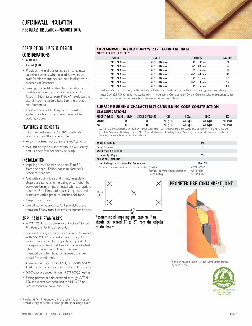
DESCRIPTION, USES & DESIGN CONSIDERATIONS• Unfaced
• Faced (FSK)
• Provides thermal performance in curtainwall spandrel systems when placed between or over framing members and held in place with mechanical fasteners.
• Semirigid, board-like fiberglass insulation is available unfaced or FSK (foil-reinforced kraft) faced in thicknesses from 1" to 4". (Evaluate the use of vapor retarders based on the project requirements.)
• Equip curtainwall buildings with sprinkler systems for fire protection as required by building codes.
FEATURES & BENEFITS• The standard size is 24" x 48"; nonstandard
lengths and widths are available.
• Accommodates most thermal specifications.
• Will not decay or slump within the wall cavity, and its fibers will not shrink or warp.
INSTALLATION• Impaling pins, if used, should be 3" to 8"
from the edges. Follow pin manufacturer’s recommendations.
• Cut with a utility knife and fit into irregularly shaped areas. Install on impaling pins, friction-fit between furring strips, or install with appropriate adhesive. Seal joints and repair facing tears and punctures with a pressure-sensitive foil tape.
• Keep product dry.
• Use adhesives appropriate for lightweight board insulation. Follow manufacturer’s recommendations.
APPLICABLE STANDARDS• ASTM C518 tests determined R-values.* Listed
R-values are for insulation only.
• Surface burning characteristics were determined with ASTM E 84, a standard used solely to measure and describe properties of products in response to heat and flame under controlled laboratory conditions. The results are not intended to reflect hazards presented under actual fire conditions.
• Complies with ASTM C612, Type 1A/1B. ASTM C 612 replaces Federal Specification HH-I-558B.
• NRC data produced through ASTM C423 testing.
• Facing permeance determined through ASTM E96 (desiccant method) and the MEA 87-84 requirements of New York City.
CURTAINWALL INSULATION/CW 225 TECHNICAL DATADENSITY 2.25 PCF—K-VALUE .23
WIDTH LENGTH THICKNESS R-VALUE1
24" 609 mm 48" 1219 mm 4" 102 mm 17.424" 609 mm 48" 1219 mm 31⁄2" 89 mm 15.224" 609 mm 48" 1219 mm 3" 76 mm 13.024" 609 mm 48" 1219 mm 21⁄2" 64 mm 10.924" 609 mm 48" 1219 mm 2" 51 mm 8.724" 609 mm 48" 1219 mm 11⁄2" 38 mm 6.524" 609 mm 48" 1219 mm 1" 25 mm 4.3
1. R-values differ. Find out why in the seller’s fact sheet on R-values. Higher R-values mean greater insulating power.
Note: CW 225 FSK-faced is not available in 1" thicknesses. Contact your Owens Corning sales representative for complete details on size availability and minimum order quantities.
SURFACE BURNING CHARACTERISTICS/BUILDING CODE CONSTRUCTION CLASSIFICATIONSPRODUCT TYPES FLAME SPREAD SMOKE DEVELOPED ICBO BOCA SBCCI ICCUnfaced 20 20 All Types All Types All Types All TypesFSK 25 50 All Types All Types All Types All Types
Curtainwall Insulation/CW 225 complies with the International Building Code (ICC), Uniform Building Code (ICBO), National Building Code (BOCA) and Standard Building Code (SBCCI) model code requirements for building construction types listed above.
VAPOR RETARDERS FSKPerms Maximum1 .02WATER VAPOR SORPTIONMaximum by Weight 5%DIMENSIONAL STABILITYLinear Shrinkage at Maximum Use Temperature Max. 2%
1. Products are tested in accordance with: R-value ASTM C518 Surface Burning Characteristics ASTM E84 Perm Rating ASTM E96
Recommended impaling pin pattern. Pins should be located 3" to 8" from the edge(s) of the board.
Up To 48"
Up To 96"
PERIMETER FIRE CONTAINMENT JOINT1
1. See approved System Listing Directories for full system details.
* R-values differ. Find out why in the seller’s fact sheet on R-values. Higher R-values mean greater insulating power.
PAGE 10 1-800-GET-PINK® www.owenscorning.com
FIBERGLAS™ 700 SERIES INSULATIONFIBERGLASS INSULATION–PRODUCT DATA
DESCRIPTION & USES• Unfaced
• FSK-faced (Foil-Scrim Kraft)
• ASJ (All Service)
• Flexible, semi-rigid and rigid rectangular boards formed from inorganic glass fibers with a thermosetting resin binder.
• 701, 702, 711—Unfaced, lightweight, resilient insulation in a sheet form, used on vessels with irregular surfaces where an exterior finish will be supported mechanically.
• 703, 704—Semi-rigid boards for use on equipment, vessels and air conditioning ductwork. Available unfaced, with factory-applied FSK, ASJ or vapor retarding facings.
• 705—High-strength, rigid board for use on equipment where high abuse resistance and good appearance are required. Available unfaced or with factory-applied FSK, ASJ or vapor retarding facings.
• 707—For acoustical wall panels and specialized ceiling applications.
FEATURES & BENEFITS• Helps save energy and reduce heat transfer.
• Available in various densities to meet specific performance, appearance and economic requirements.
• Resists damage and maintains structural integrity.
• Excellent acoustic properties.
AVAILABILITY• Fiberglas™ 700 Series Insulations are available
in standard 24" x 48" (610 mm x 1219 mm) boards with thicknesses from 1" (25 mm) to 4" (102 mm) in 1/2" (13 mm) increments. Contact your Owens Corning Sales Representative for additional sizes or if specific labeling is required for air handling.
SPECIFICATION COMPLIANCEASTM C553, Mineral Fiber Blanket Thermal Insulation, Types I, II, III—Type 701, 711ASTM C612, Mineral Fiber Block & Board Thermal Insulation, Types IA, IB—Types 702, 703, 704, 705, 707ASTM C795, Thermal Insulation For Use Over Austenitic Stainless Steel1
ASTM C1136, Flexible Low Permeance Vapor Retarders for Thermal Insulation, Type I: ASJ; Type II: FSKNuclear Regulatory Commission Guide 1.36, Non-Metallic Thermal Insulation1
New York City MEA No. 227-83—Types 703 & 705, plain and FSK-facedCAN/CGSB-51.10—Type I, Class I–Types 703, 7042
NFPA 90A and 90BCalifornia Insulation Quality Standards CA-T052
1. Preproduction qualification testing complete and on file. Chemical analysis of each production lot required for total conformance.
2. Standard obsolete, replaced by ASTM C612.
PHYSICAL PROPERTY DATAPROPERTY TEST METHOD VALUEEquipment Operating Temperature Limitation
ASTM C411 Up to 450°F (232°C)1
Insulation Jacket Temperature Limitation ASTM C1136 -20°F to 150°F (-29°C to 66°C)
Jacket Permeance ASTM E96, Proc. A 0.02 permJacket Puncture Resistance TAPPI T803 FRK: 25 units; ASJ: 50 unitsCompressive Strength (Minimum) ASTM C165 Type 703 Type 704 Type 705at 10% Deformation 25 lb/ft2 (1,197 Pa) 60 lb/ft2 (2,873 Pa) 200 lb/ft2 (9,576 Pa)
at 25% Deformation 90 lb/ft2 (4,309 Pa) 225 lb/ft2 (10.8 kPa)Water Vapor Sorption ASTM C1104 Max. 5% by WeightNominal Density ASTM C167 Type 701: 1.5 pcf (24 kg/m3)
711: 1.65 pcf (26 kg/m3)702: 2.3 pcf (37 kg/m3)
ASTM C303 703: 3.0 pcf (48 kg/m3)704: 4.2 pcf (67 kg/m3)705: 6.0 pcf (96 kg/m3)
707: 7.0 pcf (112 kg/m3)Composite Surface Burning Characteristics UL 7232, ASTM E842
or CAN/ULC-S1022
Flame Spread 252
Smoke Developed 501. Maximum thickness at 450°F (232°C): Type 701, 702: 6" (152 mm); Type 703, 704, 705: 4" (102 mm).2. The surface burning characteristics of these products have been determined in accordance with ASTM E84, UL 723
or CAN/ULC-S102. This standard should be used to measure and describe the properties of materials, products or assemblies in response to heat and flame under controlled laboratory conditions and should not be used to describe or appraise the fire hazard or fire risk of materials, products or assemblies under actual fire conditions. However, results of this test may be used as elements of a fire risk assessment which takes into account all of the factors which are pertinent to an assessment of the fire hazard of a particular end use. Values are reported to the nearest 5 rating.
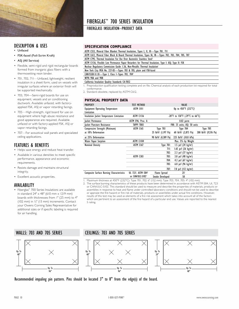
Up To 48"
Up To 96"
Recommended impaling pin pattern. Pins should be located 3" to 8" from the edge(s) of the board.
Up To 24"
Up To 48"
Up To 48"
Up To 96"
WALLS: 703 AND 705 SERIES CEILINGS: 703 AND 705 SERIES
INSULATION SYSTEMS FOR COMMERCIAL BUILDINGS PAGE 11
FIBERGLAS™ 700 SERIES INSULATIONFIBERGLASS INSULATION–PRODUCT DATA
APPLICATION RECOMMENDATIONS• Types 701 and 702 are lightweight, unfaced,
flexible insulations in batt form for use on vessels having irregular surfaces, where compressive strength is not a performance criterion.
• Types 703, 704 and 705 are board insulations usually impaled over welded pins on flat surfaces. Unfaced boards are normally finished with reinforced insulation cement or weather-proof mastic.
• ASJ-, FSK- or faced insulation boards shall be applied using mechanical fasteners such as weld pins or speed clips. Fasteners shall be located not less than 3" (75 mm) from each edge or corner of the board. Pin spacing along the equipment shall be no greater than 12" (300 mm) on center. Additional pins or clips may be required to hold the insulation tightly against the surface where cross breaking is used for stiffening. Weld pin lengths must be selected to ensure tight fit but avoid “oil canning.”
• In multiple layer applications, use faced material on outer layer only. Where a vapor retarder is required, cover pins and clips with vapor sealing, pressure-sensitive patches matching insulation facing. Rub hard with a plastic sealing tool to ensure a tight bond and a vapor seal.
• All insulation joints should be sealed with pressure-sensitive joint sealing tape to match the insulation facing. Rub hard with a plastic sealing tool to effect a tight bond. Recommended practice suggests a 3" (76 mm) wide tape on flat surfaces or where edges are shiplapped and stapled. Use 5" (102 mm) wide tape in lieu of shiplapping. If insulation is being applied to sheet metal ductwork, all sheet metal joints must be sealed prior to insulating. Glass fabric and mastic may be used in lieu of pressure sensitive tape.
• May be installed in either single or multiple layers up to a maximum of 6" (152 mm) at temperatures not over 450°F (232°C).
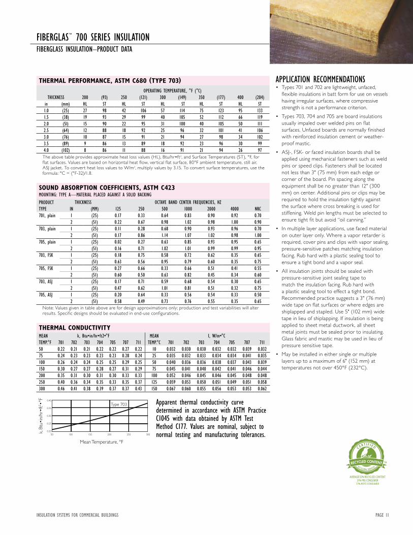
THERMAL PERFORMANCE, ASTM C680 (TYPE 703)
THICKNESSOPERATING TEMPERATURE, °F (°C)
200 (93) 250 (121) 300 (149) 350 (177) 400 (204)in (mm) HL ST HL ST HL ST HL ST HL ST1.0 (25) 27 98 42 106 57 114 75 123 95 1331.5 (38) 19 93 29 99 40 105 52 112 66 1192.0 (5l) 15 90 22 95 31 100 40 105 50 1112.5 (64) 12 88 18 92 25 96 32 101 41 1063.0 (76) 10 87 15 91 21 94 27 98 34 1023.5 (89) 9 86 13 89 18 92 23 96 30 994.0 (102) 8 86 11 88 16 91 21 94 26 97
The above table provides approximate heat loss values (HL), Btu/hr•ft2, and Surface Temperatures (ST), °F, for flat surfaces. Values are based on horizontal heat flow, vertical flat surface, 80°F ambient temperature, still air, ASJ jacket. To convert heat loss values to W/m2, multiply values by 3.15. To convert surface temperatures, use the formula: °C = (°F-32)/1.8.
SOUND ABSORPTION COEFFICIENTS, ASTM C423MOUNTING: TYPE A—MATERIAL PLACED AGAINST A SOLID BACKING
PRODUCT TYPE
THICKNESS OCTAVE BAND CENTER FREQUENCIES, HZIN (MM) 125 250 500 1000 2000 4000 NRC
701, plain 1 (25) 0.17 0.33 0.64 0.83 0.90 0.92 0.702 (51) 0.22 0.67 0.98 1.02 0.98 1.00 0.90
703, plain 1 (25) 0.11 0.28 0.68 0.90 0.93 0.96 0.702 (51) 0.17 0.86 1.14 1.07 1.02 0.98 1.00
705, plain 1 (25) 0.02 0.27 0.63 0.85 0.93 0.95 0.652 (51) 0.16 0.71 1.02 1.01 0.99 0.99 0.95
703, FSK 1 (25) 0.18 0.75 0.58 0.72 0.62 0.35 0.652 (51) 0.63 0.56 0.95 0.79 0.60 0.35 0.75
705, FSK 1 (25) 0.27 0.66 0.33 0.66 0.51 0.41 0.552 (51) 0.60 0.50 0.63 0.82 0.45 0.34 0.60
703, ASJ 1 (25) 0.17 0.71 0.59 0.68 0.54 0.30 0.652 (51) 0.47 0.62 1.01 0.81 0.51 0.32 0.75
705, ASJ 1 (25) 0.20 0.64 0.33 0.56 0.54 0.33 0.502 (51) 0.58 0.49 0.73 0.76 0.55 0.35 0.65
Note: Values given in table above are for design approximations only; production and test variabilities will alter results. Specific designs should be evaluated in end-use configurations.
THERMAL CONDUCTIVITYMEAN TEMP.°F
k, Btu•in/hr•ft2•°F MEAN TEMP.°C
I, W/m•°C701 702 703 704 705 707 711 701 702 703 704 705 707 711
50 0.22 0.21 0.21 0.22 0.22 0.27 0.22 10 0.032 0.030 0.030 0.032 0.032 0.039 0.03275 0.24 0.23 0.23 0.23 0.23 0.28 0.24 25 0.035 0.032 0.033 0.034 0.034 0.041 0.035100 0.26 0.24 0.24 0.25 0.25 0.29 0.25 50 0.040 0.036 0.036 0.038 0.037 0.043 0.039150 0.30 0.27 0.27 0.28 0.27 0.31 0.29 75 0.045 0.041 0.040 0.042 0.041 0.046 0.044200 0.35 0.31 0.30 0.31 0.30 0.33 0.33 100 0.052 0.046 0.045 0.046 0.045 0.048 0.048250 0.40 0.36 0.34 0.35 0.33 0.35 0.37 125 0.059 0.053 0.050 0.051 0.049 0.051 0.058300 0.46 0.41 0.38 0.39 0.37 0.37 0.43 150 0.067 0.060 0.055 0.056 0.053 0.053 0.062
Apparent thermal conductivity curve determined in accordance with ASTM Practice C1045 with data obtained by ASTM Test Method C177. Values are nominal, subject to normal testing and manufacturing tolerances.k,
Btu•
in/h
r•ft2 •
°F 0.40
0.35
0.30
0.25
0.2050 100 150 200 250 300
Mean Temperature, °F
Type 703
PAGE 12 1-800-GET-PINK® www.owenscorning.com
FOAMULAR® EXTRUDED POLYSTYRENE (XPS)RIGID FOAM INSULATION
DESCRIPTION & USES• FOAMULAR® 150/250 Insulation
• FOAMULAR® 400/600/1000 Insulation
• FOAMULAR® CW15/CW25 Cavity Wall Insulation
• FOAMULAR® High-R CW Plus Insulation
• FOAMULAR® INSULPINK®-Z Insulation
• FOAMULAR® PROPINK® Insulating Sheathing
• FOAMULAR® Insulating Sheathing
• FOAMULAR® INSUL-DRAIN® and PINK-DRAIN™ Insulating Drainage Board
• FOAMULAR® AGTEK Insulation
• FOAMULAR® CC High-R Insulation
• FOAMULAR® 404/604/404RB/604RB Insulation
• FOAMULAR® THERMAPINK® and DURAPINK®
Insulation
• FOAMULAR® LT30 and LT40 Insulation
• FANFOLD Damproofing Waterproofing Board (DWB)
WHAT MAKES FOAMULAR® EXTRUDED POLYSTYRENE (XPS) SUSTAINABLE?Sustainability has many definitions in the design community, but in simple terms it’s all about how the construction, use and maintenance of buildings impacts the use of resources over the long-term life of the building.
FOAMULAR® extruded polystyrene is a highly effective insulation. The energy used in making insulation products is typically saved in reduced energy usage in the first year of building occupancy.
FOAMULAR® rigid foam insulation is highly moisture resistant and will not support mold growth.** This resistance to moisture, combined with excellent compressive strength and dimensional stability, makes FOAMULAR® insulation re-usable.
FOAMULAR® is certified to meet indoor air quality standards under the stringent GREENGUARD Indoor Air Quality Certification Program® and the GREENGUARD Children & Schools Certification ProgramSM.
FOAMULAR® rigid foam insulation is made with a high percentage of pre-consumer recycled material and has been certified by SCS Global Services. FOAMULAR® insulation is also reusable.
FOAMULAR® rigid foam insulation can help contribute to credits under the Leadership in Energy and Environmental Design (LEED®) program of the U.S. Green Building Council in the following categories: Energy and Atmosphere (various credits), Materials and Resources (Resource Re-use, Recycled Content, Local Regional Materials) and Innovation & Design.
FEATURES & BENEFITS• FOAMULAR® insulation is an extruded
polystyrene rigid foam insulation
• A wide variety of standard sizes, thicknesses and compressive strengths meet the requirements of nearly every application. High-strength FOAMULAR® insulation products meet the challenge of under-slab and foundation, wall and cavity applications. Compressive strengths range from an economical 15psi—the world’s lowest density extruded polystyrene insulation—to 100 psi.
• Suited for diverse applications such as cavity walls, steel- or wood-framed wall sheathing, furred walls, foundation walls, precast and tilt-up concrete walls, under concrete slabs and in decks. Ideal for roofing applications including single-ply, tapered, BUR and protected membrane systems.
• FOAMULAR® insulation maintains 90 percent of its R-value for the lifetime† of the product and covers all ASTM C578 properties.
• Thermal performance is better than other commonly used insulating products with a long-term, aged thermal resistance (R-value*) of 5 per 1" of thickness at 75°F mean temperature.
• FOAMULAR® insulation is easy to handle and install. Extruded polystyrene insulation is lightweight, durable and impact resistant, which helps to reduce job site damage. Foam insulation can be scored and fabricated easily with common hand tools.
• Hydrophobic properties minimize wicking and contribute to excellent dimensional stability under moist conditions. Resists groundwater, condensation, water leakage and freeze/thaw cycling, but is also resistant to the effects of fungus, mildew, corrosion and common soil acids. Moisture resistance helps to maintain thermal performance over the life of the product.
• Panels are available with square edge, shiplap or tongue and groove edge to further reduce air infiltration.
STANDARDS, CODES COMPLIANCE • Meets ASTM C578
• UL Classified. A copy of UL Classification Certificate U-197 is available at www.foamular.com
• See UL ER8811-01 at UL.com
• Fire rated wall and roof assemblies including ASTM E119, E108, NFPA 285, UL 1256 and FM Class I
• Meets California Quality Standards; HUD UM #71A
• Compliance verification by RADCO (AA-650)
DESIGN CONSIDERATIONSThis product is combustible. A thermal barrier is required as specified in the appropriate building code. For additional information, consult MSDS or contact Owens Corning World Headquarters at 1-800-GET-PINK®.
• Many solvent-laden mastics, and some plastic- or oil-based adhesives are not compatible with polystyrene-based insulations.
• Take provisions to protect the insulation from excessive exposure to direct sunlight by covering it as soon as possible.
• In horizontal roof and under slab applications, place foam with black lettering and logo facing down.
• Evaluate all constructions to assess the necessity for providing vapor retarders to avoid condensation and subsequent structural damage. (See the current ASHRAE Handbook of Fundamentals.)
* R-values differ. Find out why in the seller’s fact sheet on R-values. Higher R-values mean greater insulating power.
** As manufactured, Fiberglas™ insulation is resistant to mold growth. However, mold growth can occur on building materials, including insulation, when it becomes contaminated with organic material and when water is present. To avoid mold growth on Fiberglas™ insulation, remove any water that has accumulated and correct or repair the source of the water as soon as possible. Insulation that has become wet should be inspected for evidence of residual moisture and contamination, and any insulation that is contaminated should be promptly removed and replaced.
† See actual warranty for details.
INSULATION SYSTEMS FOR COMMERCIAL BUILDINGS PAGE 13
FOAMULAR® EXTRUDED POLYSTYRENE (XPS)RIGID FOAM INSULATION
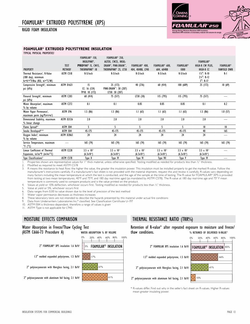
Water Absorption in Freeze/Thaw Cycling Test (ASTM C666-73 Procedure A)
Retention of R-value* after repeated exposure to moisture and freeze/thaw conditions.
2" FOAMULAR XPS insulation 1.6 lb/ft3
1.5" molded expanded polystyrene, 1.5 lb/ft3
2" polyisocyanurate with fiberglass facing, 2.1 lb/ft3
2" polyisocyanurate with aluminum foil facing, 2.1 lb/ft3
% RETAINED OF DELIVERED R-VALUE*
FOAMULAR® INSULATION
FOAMULAR® INSULATION2" FOAMULAR® XPS insulation 1.6 lb/ft3
1.5" molded expanded polystyrene, 1.5 lb/ft3
2" polyisocyanurate with fiberglass facing, 2.1 lb/ft3
2" polyisocyanurate with aluminum foil facing, 2.1 lb/ft3
FOAMULAR® INSULATION
FOAMULAR® INSULATION
WATER ABSORPTION % BY VOLUME
FOAMULAR® EXTRUDED POLYSTYRENE INSULATIONTYPICAL PHYSICAL PROPERTIES1
PROPERTYTEST
METHOD2
FOAMULAR® 150, INSULPINK®,
PROPINK® IS, CW15, THERMAPINK® 18
FOAMULAR® 250, AGTEK, CW25, INSUL-DRAIN®, PINK-DRAIN™, THERMAPINK® 25, LT30
FOAMULAR® 400, 404, 404RB, LT40
FOAMULAR® 600, 604, 604RB
FOAMULAR® 1000
FOAMULAR® HIGH-R CW PLUS,
HIGH-R CCFOAMULAR®
FANFOLD DWBThermal Resistance3, R-Value (180 day), minimum hr•ft2•°F/Btu (RSI, m2•°C/W)
ASTM C518 R-5/inch R-5/inch R-5/inch R-5/inch R-5/inch 17⁄8": R-10 21⁄8": R-12 3": R-17
R-1
Compressive Strength4, minimum psi (kPa)
ASTM D1621 15 CC: 16 (124)
TP18: 18 (172)
25 (172) PINK-DRAIN™: 30 (207)
LT30: 30 (207)
40 (276) 60 (414) 100 (689) 25 (172) 10 (69)
Flexural Strength5, minimum psi (kPa)
ASTM C203 60 (414) 75 (517) LT30 (30) 115 (793) 115 (793) 75 (517) —
Water Absorption6, maximum % by volume
ASTM C272 0.1 0.1 0.05 0.05 0.05 0.1 0.2
Water Vapor Permeance7, maximum perm (ng/Pa•s•m2)
ASTM E96 1.5 (86) 1.5 (86) 1.1 (63) 1.1 (63) 1.1 (63) 1.5 (86) 1.0 (57)
Dimensional Stability, maximum % linear change
ASTM D2126 2.0 2.0 2.0 2.0 2.0 2.0 —
Flame Spread8,9 ASTM E84 5 5 5 5 5 10 10Smoke Developed8,9,10 ASTM E84 45-175 45-175 45-175 45-175 45-175 40 165Oxygen Index8, minimum % by volume
ASTM D2863 24 24 24 24 24 24 —
Service Temperature, maximum °F (°C)
— 165 (74) 165 (74) 165 (74) 165 (74) 165 (74) 165 (74) 165 (74)
Linear Coefficient of Thermal Expansion, in/in/ºF (m/m/°C)
ASTM E228 3.5 x 10⁻⁵ (6.3x10⁻⁵)
3.5 x 10⁻⁵ (6.3x10⁻⁵)
3.5 x 10⁻⁵ (6.3x10⁻⁵)
3.5 x 10⁻⁵ (6.3x10⁻⁵)
3.5 x 10⁻⁵ (6.3x10⁻⁵)
3.5 x 10⁻⁵ (6.3x10⁻⁵)
—
Type Classifications11 ASTM C578 Type X Type IV Type VI Type VII Type V Type IV —1. Properties shown are representative values for 1” thick material, unless otherwise specified. Testing modified as needed for products less than 1/2” thickness.2. Modified as required to meet ASTM C5783. R means the resistance to heat flow; the higher the value, the greater the insulation power. This insulation must be installed properly to get the marked R-value. Follow the
manufacturer’s instructions carefully. If a manufacturer’s fact sheet is not provided with the material shipment, request this and review it carefully. R-values vary depending on many factors including the mean temperature at which the test is conducted, and the age of the sample at the time of testing. The R-value for FOAMULAR® XPS is provided from testing at two mean temperatures, 40ºF and 75ºF, and 180 day real-time aged (as mandated by ASTM C578). The R-value at 180 day real-time age and 75º F mean temperature is commonly used to compare products and is the value printed on the product.
4. Values at yield or 10% deflection, whichever occurs first. Testing modified as needed for products less than 1/2” thickness.5. Value at yield or 5%, whichever occurs first6. Data ranges from 0.00 to value shown due to the level of precision of the test method7. Water vapor permeance decreases as thickness increases8. These laboratory tests are not intended to describe the hazards presented by this material under actual fire conditions9. Data from Underwriters Laboratories Inc.® classified. See Classification Certificate U-19710. ASTM E84 is thickness-dependent, therefore a range of values is given11. ASTM Type is not applicable for LT40.
MOISTURE EFFECTS COMPARISON THERMAL RESISTANCE RATIO (TRR%)
* R-values differ. Find out why in the seller’s fact sheet on R-values. Higher R-valuesmean greater insulating power.
PAGE 14 1-800-GET-PINK® www.owenscorning.com
ELAMINATOR® METAL BUILDING INSULATION SYSTEMFIBERGLASS INSULATION–PRODUCT DATA
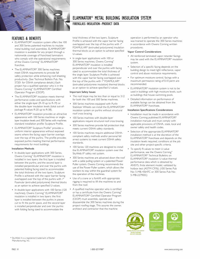
FEATURES & BENEFITS• ELAMINATOR® insulation system offers the 100
and 300 Series patented machines to insulate metal building roof assemblies. ELAMINATOR® insulation is available for any project through a nationwide coverage of franchised laminators who comply with the operational requirements of the Owens Corning™ ELAMINATOR® franchise.
• The ELAMINATOR® 300 Series machines meet OSHA requirements to provide fall safety protection while enhancing roof-sheeting productivity. (See Technical Bulletin Pub. No. 57201 for OSHA compliance details.) Each project has a qualified operator who is in the Owens Corning™ ELAMINATOR® Certified Operator Program (CEOP).
• The ELAMINATOR® insulation meets thermal performance codes and specifications with either the single-layer (R-10 up to R-19) or the double-layer insulation levels (total out-of-package R-values R-20 up to R-38).
• ELAMINATOR® insulation provides an attractive appearance with 100 Series machines or single-layer insulation levels and 300 Series with machines standard installation profile: Sculpture Profile.
• ELAMINATOR® Sculpture Profile™ provides a uniform interior appearance without exposed seams where the facing vapor barrier overlaps over the top of the purlins. The profile provides exposed purlins meeting thermal performance requirements for most buildings.
Installation Methods
• In double-layer applications with 300 Series, Owens Corning™ ELAMINATOR® insulation is installed in two layers: the first layer is installed between the purlins, and the second layer is installed perpendicular and over the purlins with patented folding facing sized to accommodate the total thickness of the two layers. Sculpture Profile is achieved with the vapor barrier facing overlapped over the top of the purlins with 1" Foamular (extruded polystyrene) thermal blocks as an option to achieve specified U-values.
• In double-layer applications with 100 Series (120 machines), Owens Corning™ ELAMINATOR® insulation is installed in two layers: the first layer is installed between the purlins in pieces cut to fit the purlin space, and the second layer is installed perpendicular and over the purlins with folding facing sized to accommodate the
total thickness of the two layers. Sculpture Profile is achieved with the vapor barrier facing overlapped over the top of the purlins with 1" FOAMULAR® (extruded polystyrene) insulation thermal blocks as an option to achieve specified U-values.
• In single-layer applications with 100 or 300 Series machines, Owens Corning™ ELAMINATOR® insulation is installed perpendicular and over the purlins with facing sized to accommodate the total thickness of the single layer. Sculpture Profile is achieved with the vapor barrier facing overlapped over the top of the purlins with 1" FOAMULAR® (extruded polystyrene insulation) thermal blocks as an option to achieve specified U-values.
Important Safety Issues
• The roof slope may be less than or equal to 3:12 for both the 100 and 300 Series machines.
• 300 Series machines equipped with Purlin Stabilizer Wheels can install the ELAMINATOR® insulation system on purlins without structural roof cross bracing.
• 100 Series machines with double-layer applications require structural roof cross bracing.
• 300 Series machines provide fall protection that meets current OSHA safety standards.
• 100 Series machines require additional OSHA- compliant safety methods and/or personal fall arrest systems to meet current OSHA safety standards.
• 100 Series 120 machines are designed to install the ELAMINATOR® insulation system over the SkyWeb II® safety net system.
• 300 Series machines are advanced down the roof with a cable pulling system or a patented Power Puller system. Owens Corning recommends the use of the Power Puller system, which allows the workers to stay within the guardrail system for the operation of the machines.
• Use of a crane or a forklift with appropriate rigging is required to lift the machines to and from the roof.
• A qualified machine operator who is certified or has a certificate from the Owens Corning™ ELAMINATOR® Certified Operator Program (CEOP) must assemble, operate and disassemble the 300 Series machines during the project roofing stage. This assures the owner, architect and contractor that the machine
operation is performed by an operator who was trained to operate the 300 Series machines in accordance with Owens Corning written procedures.
Vapor Control Considerations
• All reinforced laminated vapor retarder facings may be used with the ELAMINATOR® insulation system.
• Selection of a specific facing depends on the building design to meet light reflectance, vapor control and abuse resistance requirements.
• For optimum moisture control, facings with a maximum permeance rating of 0.10 perm are recommended.
• ELAMINATOR® insulation system is not to be used in buildings with high moisture levels, such as buildings that house swimming pools.
• Detailed information on performance of available facings can be obtained from the ELAMINATOR® franchisee.
Installation Specifications Considerations
• Installation must be made in accordance with Owens Corning published ELAMINATOR® installation manuals and must comply with applicable provisions of OSHA, state, local and owner safety and health codes.
• Selection of the appropriate ELAMINATOR® installation method is at the discretion of the ELAMINATOR® franchisee and depends on the insulation levels required, conditions at the job site and other project-specific criteria.
• To specify R-values to meet U-value performance, see the Owens Corning™ ELAMINATOR® Technical Bulletins on ELAMINATOR® insulation U-value thermal performance data which is obtained by ANSYS, finite element model, validated by hotbox test (ASTM C976). (100 Series Pub No: 5-MB-43647C or 300 Series Pub No: 5-MB-22790D.)
* SkyWeb II is a registered trademark of Butler Manufacturing, Inc.
INSULATION SYSTEMS FOR COMMERCIAL BUILDINGS PAGE 15
CERTIFIED R METAL BUILDING INSULATIONFIBERGLASS INSULATION–PRODUCT DATA
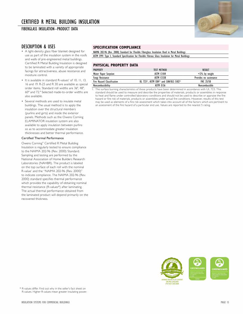
DESCRIPTION & USES• A light-density glass fiber blanket designed for
use as part of the insulation system in the roofs and walls of pre-engineered metal buildings. Certified R Metal Building Insulation is designed to be laminated with a variety of appropriate facings for attractiveness, abuse resistance and moisture control.
• It is available in standard R-values* of 10, 11, 13, 16 and 19. R-25 and R 30 are available as special order items. Standard roll widths are 36", 48", 60" and 72." Selected made-to-order widths are also available.
• Several methods are used to insulate metal buildings. The usual method is to apply the insulation over the structural members (purlins and girts) and inside the exterior panels. Methods such as the Owens Corning ELAMINATOR insulation system are also available to apply insulation between purlins so as to accommodate greater insulation thicknesses and better thermal performance.
Certified Thermal Performance
Owens Corning™ Certified R Metal Building Insulation is regularly tested to ensure compliance to the NAIMA 202-96 (Rev. 2000) Standard. Sampling and testing are performed by the National Association of Home Builders Research Laboratories (NAHBR). The product is labeled on the top surface of each roll with the nominal R-value* and the “NAIMA 202-96 (Rev. 2000)” to indicate compliance. The NAIMA 202-96 (Rev. 2000) standard specifies thermal performance which provides the capability of obtaining nominal thermal resistance (R-values*) after laminating. The actual thermal performance obtained from the laminated product will depend primarily on the recovered thickness.
SPECIFICATION COMPLIANCENAIMA 202-96 (Rev. 2000) Standard for Flexible Fiberglass Insulation Used in Metal BuildingsASTM C991 Type I, Standard Specification for Flexible Fibrous Glass Insulation for Metal Buildings
PHYSICAL PROPERTY DATAPROPERTY TEST METHOD RESULTWater Vapor Sorption ASTM C1104 <2% by weightFungi Resistance ASTM C1338 Provides no sustenanceFire Hazard Classification UL 723(1), ASTM E84(1) and CAN/ULS S102(1) FHC 25/50Noncombustibility ASTM E136 Noncombustible
1. The surface burning characteristics of these products have been determined in accordance with UL 723. This standard should be used to measure and describe the properties of materials, products or assemblies in response to heat and flame under controlled laboratory conditions and should not be used to describe or appraise the fire hazard or fire risk of materials, products or assemblies under actual fire conditions. However, results of this test may be used as elements of a fire risk assessment which takes into account all of the factors which are pertinent to an assessment of the fire hazard of a particular end use. Values are reported to the nearest 5 rating.
* R-values differ. Find out why in the seller’s fact sheet on R-values. Higher R-values mean greater insulating power.
PAGE 16 1-800-GET-PINK® www.owenscorning.com
APPLICATION RECOMMENDATIONSINSULATION SYSTEMS FOR COMMERCIAL BUILDINGS
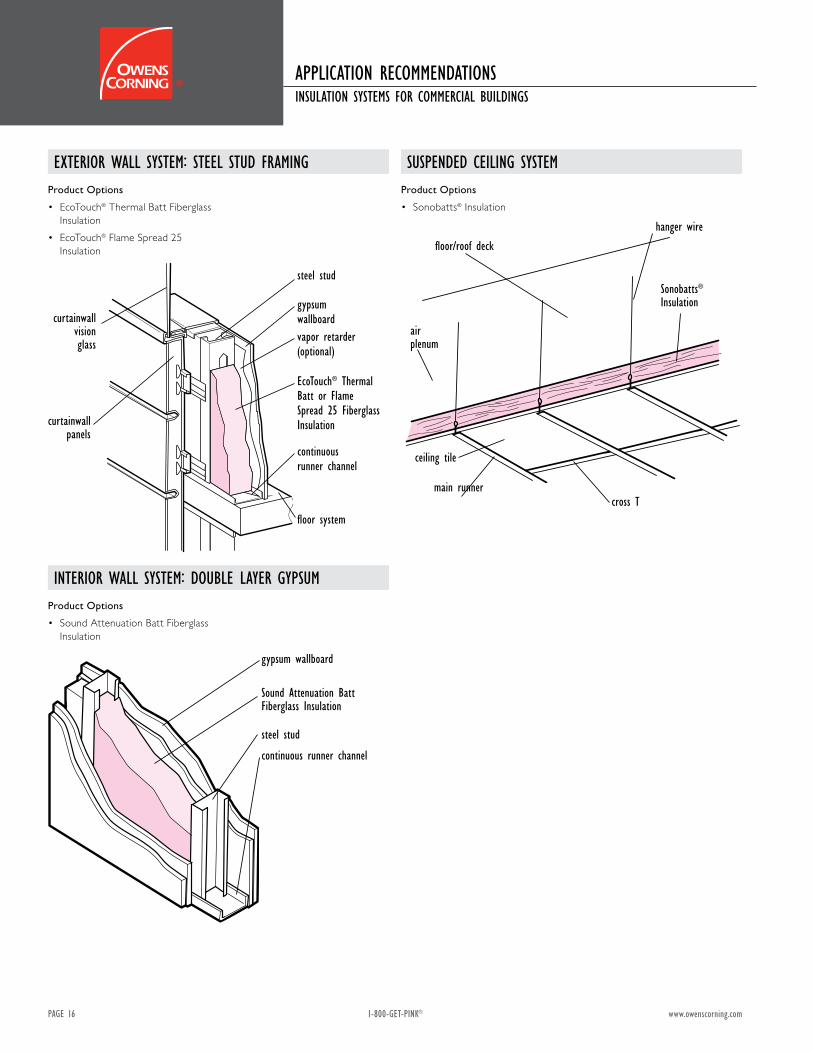
Product Options
• Sound Attenuation Batt Fiberglass Insulation
Product Options
• EcoTouch® Thermal Batt Fiberglass Insulation
• EcoTouch® Flame Spread 25 Insulation
steel stud
curtainwall vision glass
curtainwall panels
gypsum wallboardvapor retarder (optional)
EcoTouch® Thermal Batt or Flame Spread 25 Fiberglass Insulation
continuous runner channel
floor system
continuous runner channel
Sound Attenuation Batt Fiberglass Insulation
steel stud
gypsum wallboard
Product Options
• Sonobatts® Insulation
hanger wire
floor/roof deck
Sonobatts® Insulation
ceiling tile
main runnercross T
air plenum
EXTERIOR WALL SYSTEM: STEEL STUD FRAMING
INTERIOR WALL SYSTEM: DOUBLE LAYER GYPSUM
SUSPENDED CEILING SYSTEM
INSULATION SYSTEMS FOR COMMERCIAL BUILDINGS PAGE 17
APPLICATION RECOMMENDATIONSINSULATION SYSTEMS FOR COMMERCIAL BUILDINGS
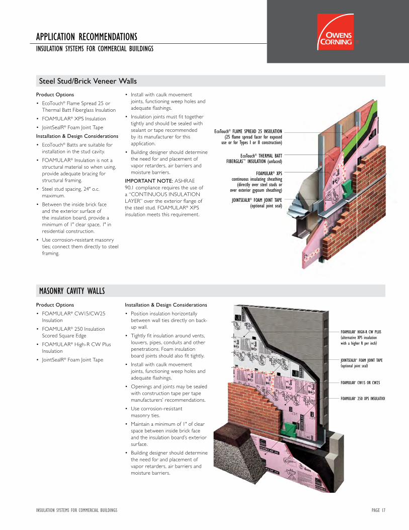
Product Options
• EcoTouch® Flame Spread 25 or Thermal Batt Fiberglass Insulation
• FOAMULAR® XPS Insulation
• JointSealR® Foam Joint Tape
Installation & Design Considerations
• EcoTouch® Batts are suitable for installation in the stud cavity.
• FOAMULAR® Insulation is not a structural material so when using, provide adequate bracing for structural framing.
• Steel stud spacing, 24" o.c. maximum.
• Between the inside brick face and the exterior surface of the insulation board, provide a minimum of 1" clear space, 1" in residential construction.
• Use corrosion-resistant masonry ties; connect them directly to steel framing.
• Install with caulk movement joints, functioning weep holes and adequate flashings.
• Insulation joints must fit together tightly and should be sealed with sealant or tape recommended by its manufacturer for this application.
• Building designer should determine the need for and placement of vapor retarders, air barriers and moisture barriers.
IMPORTANT NOTE: ASHRAE 90.1 compliance requires the use of a “CONTINUOUS INSULATION LAYER” over the exterior flange of the steel stud. FOAMULAR® XPS insulation meets this requirement.
JOINTSEALR® FOAM JOINT TAPE
Product Options
• FOAMULAR® CW15/CW25 Insulation
• FOAMULAR® 250 Insulation Scored Square Edge
• FOAMULAR® High-R CW Plus Insulation
• JointSealR® Foam Joint Tape
Installation & Design Considerations
• Position insulation horizontally between wall ties directly on back-up wall.
• Tightly fit insulation around vents, louvers, pipes, conduits and other penetrations. Foam insulation board joints should also fit tightly.
• Install with caulk movement joints, functioning weep holes and adequate flashings.
• Openings and joints may be sealed with construction tape per tape manufacturers’ recommendations.
• Use corrosion-resistant masonry ties.
• Maintain a minimum of 1" of clear space between inside brick face and the insulation board’s exterior surface.
• Building designer should determine the need for and placement of vapor retarders, air barriers and moisture barriers.
Steel Stud/Brick Veneer Walls
MASONRY CAVITY WALLS
EcoTouch® FLAME SPREAD 25 INSULATION (25 flame spread facer for exposed
use or for Types I or II construction)
EcoTouch® THERMAL BATT FIBERGLAS™ INSULATION (unfaced)
FOAMULAR® XPS continuous insulating sheathing
(directly over steel studs or over exterior gypsum sheathing)
JOINTSEALR® FOAM JOINT TAPE (optional joint seal)
ECOTOUCH® FLAME SPREAD 25 INSULATION(25 ame spread facer for exposed
use or for Types I or II construction)
ECOTOUCH® PINK® FIBERGLAS™
INSULATION (unfaced)
FOAMULAR® 250 XPScontinuous insulating sheathing
(directly over steel studs orover exterior gypsum sheathing)
JOINTSEALR® FOAM JOINT TAPE(optional joint seal)
PAGE 18 1-800-GET-PINK® www.owenscorning.com
APPLICATION RECOMMENDATIONSINSULATION SYSTEMS FOR COMMERCIAL BUILDINGS
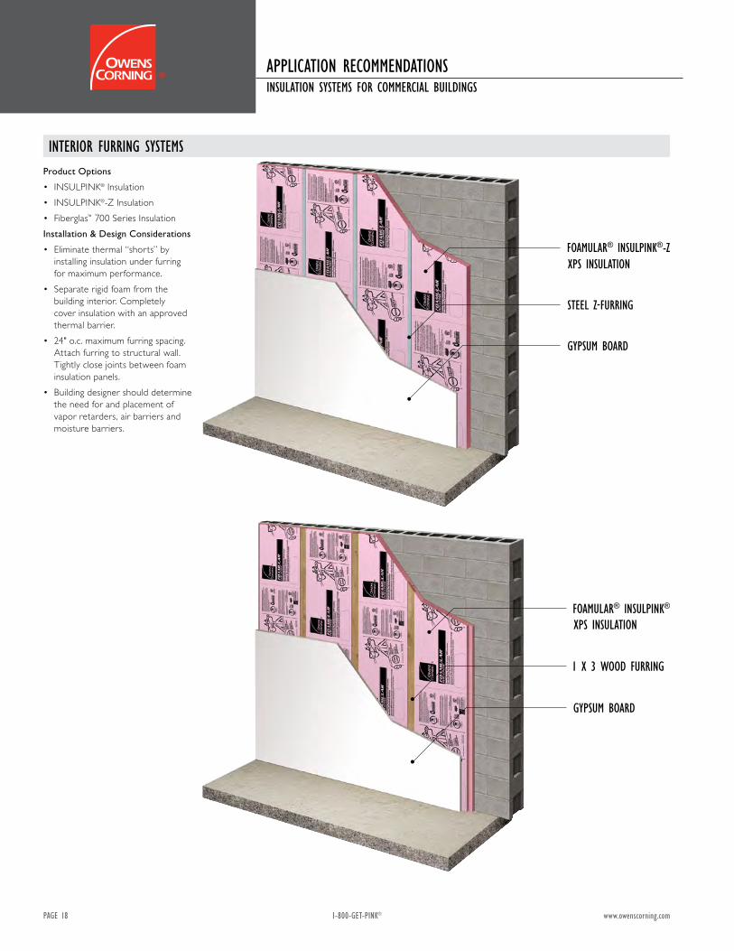
Product Options
• INSULPINK® Insulation
• INSULPINK®-Z Insulation
• Fiberglas™ 700 Series Insulation
Installation & Design Considerations
• Eliminate thermal “shorts” by installing insulation under furring for maximum performance.
• Separate rigid foam from the building interior. Completely cover insulation with an approved thermal barrier.
• 24" o.c. maximum furring spacing. Attach furring to structural wall. Tightly close joints between foam insulation panels.
• Building designer should determine the need for and placement of vapor retarders, air barriers and moisture barriers.
FOAMULAR® INSULPINK®-Z
FOAMULAR® INSULPINK®
INTERIOR FURRING SYSTEMS

INSULATION SYSTEMS FOR COMMERCIAL BUILDINGS PAGE 19
Product Options
• FOAMULAR® 250 Extruded Polystyrene Rigid Foam Insulation
• Thermomass System NC
• Thermomass System SC
• Thermomass System CIP
Installation & Design Considerations
• Low-conductivity ties are designed to hold the fascia in place without a concrete-foam bond or solid concrete sections in the panel.
• Minimum wythe thicknesses should be as recommended by the tie system manufacturers.
• Minimum tie spacings should be as recommended by the tie system manufacturers.
• For maximum panel thermal performance, eliminate solid sections of concrete.
• Thermomass connectors are fiber-composite connectors. Follow manufacturers recommendations for structural performance.
• Consolidate concrete in forms by vibrating, walking or other recommended means.
ECOTOUCH® FLAME SPREAD 25 INSULATION
ECOTOUCH® THERMAL BATTFIBERGLAS™ INSULATION (unfaced)
FOAMULAR® 250 XPScontinuous insulation
THERMOMASS SYSTEM SC
THERMOMASS SYSTEM NC
THERMOMASS SYSTEM NC
THERMOMASS SYSTEM CIP
PRECAST/TILT-UP WALLS/VERTICAL POUR
APPLICATION RECOMMENDATIONSINSULATION SYSTEMS FOR COMMERCIAL BUILDINGS
THERMOMASS SYSTEM SCor THERMOMASS SYSTEM NC
THERMOMASS SYSTEM SCor THERMOMASS SYSTEM NC
PAGE 20 1-800-GET-PINK® www.owenscorning.com
APPLICATION RECOMMENDATIONSINSULATION SYSTEMS FOR COMMERCIAL BUILDINGS
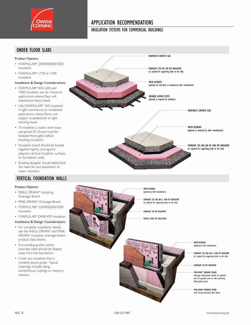
Product Options
• FOAMULAR® 250/400/600/1000 Insulation
• FOAMULAR® LT30 or LT40 Insulation
Installation & Design Considerations
• FOAMULAR® 400, 600 and 1000 Insulation are for industrial applications where floor will experience heavy loads.
• Use FOAMULAR® 250 Insulation in light commercial or residential applications where floors are subject to pedestrian or light working loads.
• To establish a stable, even base, use gravel fill. Gravel must be tamped thoroughly before installing insulation.
• Insulation board should be butted together tightly, and against adjacent vertical insulation surfaces or foundation walls.
• Building designer should determine the need for and placement of vapor retarders.
VAPOR RETARDER
UNDER FLOOR SLABS
Product Options
• INSUL-DRAIN® Insulating Drainage Board
• PINK-DRAIN® Drainage Board
• FOAMULAR® 250/400/600/1000 Insulation
• FOAMULAR® DWB XPS Insulation
Installation & Design Considerations
• For complete installation details, see the INSUL-DRAIN® and PINK-DRAIN® insulation drainage board product data sheets.
• Surrounding grades and/or concrete slabs should be sloped away from the foundation.
• Cover any insulation that is installed above grade. Typical coverings include siding, cementitious coatings or masonry veneers.
VERTICAL FOUNDATION WALLS
INSULATION SYSTEMS FOR COMMERCIAL BUILDINGS PAGE 21
ENVIRONMENTAL AND SUSTAINABILITYINSULATION SYSTEMS FOR COMMERCIAL BUILDINGS
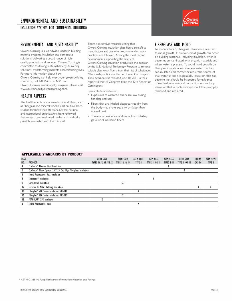
ENVIRONMENTAL AND SUSTAINABILITYOwens Corning is a worldwide leader in building material systems, insulation and composite solutions, delivering a broad range of high-quality products and services. Owens Corning is committed to driving sustainability by delivering solutions, transforming markets and enhancing lives. For more information about how Owens Corning can help meet your green building standards, call 1-800-GET-PINK®. For Owens Corning sustainability progress, please visit www.sustainability.owenscorning.com.
HEALTH ASPECTSThe health effects of man-made mineral fibers, such as fiberglass and mineral wool insulation, have been studied for more than 50 years. Several national and international organizations have reviewed that research and evaluated the hazards and risks possibly associated with this material.
There is extensive research stating that Owens Corning insulation glass fibers are safe to manufacture and use when recommended work practices are followed. Among the most recent developments supporting the safety of Owens Corning insulation products is the decision by the U.S. National Toxicology Program to remove soluble glass wool fibers from their list of substances “Reasonably anticipated to be Human Carcinogen”. Their decision was released June 10, 2011, in their report to the US Congress titled the 12th Report on Carcinogens.
Research demonstrates:• Exposures to airborne fibers are low during
handling and use.
• Fibers that are inhaled disappear rapidly from the body—at a rate equal to or faster than normal dust.
• There is no evidence of disease from inhaling glass wool insulation fibers.
FIBERGLASS AND MOLDAs manufactured, fiberglass insulation is resistant to mold growth.* However , mold growth can occur on building materials, including insulation, when it becomes contaminated with organic materials and when water is present. To avoid mold growth on fiberglass insulation, remove any water that has accumulated and correct or repair the source of that water as soon as possible. Insulation that has become wet should be inspected for evidence of residual moisture and contamination, and any insulation that is contaminated should be promptly removed and replaced.
APPLICABLE STANDARDS BY PRODUCTPAGE NO. PRODUCT
ASTM C578TYPES IV, V, VI, VII, X
ASTM C612TYPES IA & IB
ASTM C665TYPE I
ASTM C665TYPES I OR II
ASTM C665TYPES I-III
ASTM C665TYPE II OR III
NAIMA202-96
ASTM C991TYPE I
4 EcoTouch® Thermal Batt Insulation X5 EcoTouch® Flame Spread 25/FS25 Ext. Flgs Fiberglass Insulation X6 Sound Attenuation Batt Insulation X8 Sonobatts® Insulation X9 Curtainwall Insulation X15 Certified R Metal Building Insulation X X10 Fiberglas™ 700 Series Insulation: 701-711 X10 Fiberglas™ 700 Series Insulation: 703-705 X12 FOAMULAR® XPS Insulation X6 Sound Attenuation Batts X
* ASTM C1338-96 Fungi Resistance of Insulation Materials and Facings.
PAGE 22 1-800-GET-PINK® www.owenscorning.com
ATTACHMENT SYSTEMSINSULATION SYSTEMS FOR COMMERCIAL BUILDINGS
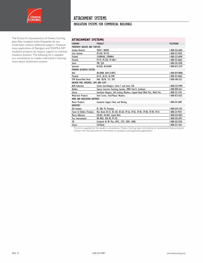
The friction-fit characteristics of Owens Corning glass fiber insulation batts frequently let you install them without additional support. However, many applications of fiberglass and FOAMULAR® insulation products do require support to maintain insulation position. The following list is supplied as a convenience to readers interested in learning more about attachment systems.
ATTACHMENT SYSTEMSCOMPANY PRODUCT TELEPHONEPNEUMATIC NAILERS AND STAPLERSStanley Bostitch TU20-7, RN45B 1-800-556-6696Linic Systems HT-550, HT-755 1-800-513-9918Paslode 3150W16R, 3200W16 1-800-222-6990Pneutek PT-79, PT-250, PT-300-I 1-800-431-8665Senco PW, SJ10 1-800-543-4596Spotnails HL1620, HL7616AP 1-800-873-2239POWDER ACTUATED SYSTEMSHilti DX-600N, XA41-X-AM72 1-800-879-8000Pneutek FA-75, SA-45, SA-75W 1-800-431-8665ITW Ramset/Red Head D60, SA270, 721, D45 1-800-348-3231ANCHOR PINS, WASHERS, CAPS AND CLIPSAGM Industries Tactoo Insul-Hangers, Series T and Series TSA 1-800-225-9990Buildex Tapcon Concrete Fastening Systems, HWH Teks/3, Gridmate 1-800-848-5611Gemco Insulation Hangers, Self Locking Washers, Cupped Head Weld Pins, Weld Pins 1-800-331-1164Wind-lock Products Steel Screws, Steel/Plastic Washers 1-800-872-5625WIRE AND INSULATION SUPPORTSMoore Products Insulation Support Rods and Netting 1-800-241-5807ADHESIVESOSI Sealants PL 200, PL Premium 1-800-624-7767Foster & Childers Products Max Bond, 85-15, 85-120, 85-60, CP-56, CP-82, CP-85, CP-88, CP-89, CP-35 1-800-231-9541Macco Adhesives LN-601, LN-604, Liquid Nails 1-800-634-0015Tacc International MA-4062, DSA-40, PF-101 1-800-503-69913M Fastbond 42 NF Plus, 847L, 1357, 1870, 1300L 1-800-362-3550Gemco Tuff-Bond 1-800-331-1164
This list is supplied for the reader’s convenience. Owens Corning does not endorse or recommend these products. Contact the manufacturer for information on products and approved applications.
INSULATION SYSTEMS FOR COMMERCIAL BUILDINGS PAGE 23
GUIDE SPECIFICATIONSINSULATION SYSTEMS FOR COMMERCIAL BUILDINGS
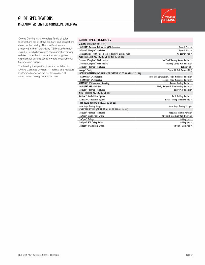
Owens Corning has a complete family of guide specifications for all of the products and applications shown in this catalog. The specifications are presented in the standardized CSI MasterFormat® 3-part style which facilitates communication among architects, specifiers, contractors and suppliers, helping meet building codes, owners’ requirements, timelines and budgets.
The listed guide specifications are published in Owens Corning’s Division 7: Thermal and Moisture Protection binder or can be downloaded at www.owenscorningcommercial.com.
GUIDE SPECIFICATIONSGENERAL INSULATION (07 21 00)FOAMULAR® Extruded Polystyrene (XPS) Insulation General ProductEcoTouch® Fiberglas™ Insulation General ProductEnergyComplete™ with Flexible Seal Technology, Exterior Wall Air Barrier SystemWALL INSULATION SYSTEMS (07 21 00 AND 07 24 00)CommercialComplete™ Wall Systems Steel Stud/Masonry Veneer InsulationCommercialComplete™ Wall Systems Masonry Cavity Wall InsulationEcoTouch® Fiberglas™ Insulation Exterior WallSenergy®, Sentry Stucco CI Wall System (EIFS)ROOFING/WATERPROOFING INSULATION SYSTEMS (07 22 00 AND 07 21 00)THERMAPINK® XPS Insulation New Roof Construction, Below Membrane InsulationTHERMAPINK® XPS Insulation Tapered, Below Membrane InsulationDURAPINK® XPS Insulation, Reroofing Recover Roofing Insulation FOAMULAR® XPS Insulation PRMA, Horizontal Waterproofing Insulation EcoTouch® Fiberglas™ Insulation Below Deck Insulation METAL BUILDING SYSTEMS (07 21 00)Optiliner™ Banded Liner System Metal Building Insulation ELAMINATOR® Insulation System Metal Building Insulation SystemSTEEP SLOPE ROOFING SHINGLES (07 31 00)Steep Slope Roofing Shingles Steep Slope Roofing ShinglesACOUSTICAL SYSTEMS (09 54 00, 09 81 00 AND 09 84 00) EcoTouch® Fiberglas™ Insulation Acoustical Interior Partition EuroSpan® Stretch Wall System Stretched Acoustical Wall Treatment EuroSpan® Ceilings Ceiling System EuroSpan® EOS Ceiling System Ceiling System EuroSpan® Translucence System Stretch Fabric System

PAGE 24 1-800-GET-PINK® www.owenscorning.com
ASTM E84: Standard Test Method for Surface Burning Characteristics of Building Materials*
Test determines the relative burning behavior of building materials by observing the flame spread along a specimen in the ceiling position. Both flame spread and smoke developed are reported to the nearest 5 rating.
ASTM E90 Standard Method for Laboratory Measurement of Airborne Sound Transmission Loss in Building PartitionsTest covers lab measures of airborne sound transmission loss in partitions such as walls, floor/ceiling assemblies, doors and other dividing elements.
ASTM E96 Standard Test Method for Water Vapor Transmission of MaterialsTest covers transmission of water vapor through materials. Commonly applied to paper, plastic films, fiberboard, gypsum and other sheet plastics and wood materials.
ASTM E119 Standard Test Method for Fire Tests of Building Construction and Materials*
Test determines the time duration for which construction material assemblies will contain a fire, retain their structural integrity or exhibit both properties during a standardized exposure to fire.
ASTM E136 Standard Test Method for Behavior of Materials in Vertical Tube Furnace at 750°C*
Test determines the combustion characteristics of building materials under specific laboratory conditions. Not intended for coated or laminated materials.
ASTM C177 Standard Test Method for Steady-State Thermal Transmission Properties by Means of the Guarded Hot PlateTest uses a guarded hot plate to measure the steady-state thermal transmission properties of insulating specimens. Test accuracy may be difficult to verify when testing specimens of low-density thermal insulation.
ASTM C423 Standard Test Method for Sound Absorption and Sound Absorption Coefficient by the Reverberation Room MethodTest determines the sound absorption coefficients of samples measured over 1⁄3 octave bands, reported at preferred octave band center frequencies. Several defined mounting conditions are used for testing samples.
ASTM C518 Standard Test Method for Steady-State Thermal Transmission Properties by Means of the Heat Flow MeterTest covers the steady-state thermal transmission properties of thermal insulation specimens using a heat flow meter. Test complements and compares specimen data to ASTM C177.
ASTM C523 Standard Test Method for Light Reflectance of Acoustical Materials by Integrating Sphere ReflectometerTest measures the light reflectivity of acoustical materials and is generally used to predict the room lighting requirements. Results are expressed as a percentage of the incident light reflected by the surface.
ASTM C553 Standard Specification for Mineral Fiber Blanket Thermal Insulation for Commercial and Industrial ApplicationsSpecification covers the composition, dimensions and physical properties of mineral fiber blanket intended for use as thermal insulation on surfaces at temperatures from subambient up to 1,200°F (649°C).
ASTM C578 Standard Specification for Rigid Cellular Polystyrene Thermal InsulationSpecification covers the types, dimensions and physical properties of cellular polystyrene intended for use as thermal insulation at temperatures from -65 to +165°F (-54 to +74°C).
ASTM C612 Standard Specification for Mineral Fiber Block and Board Thermal InsulationSpecification covers the dimensions, composition and physical properties of mineral fiberboard insulation for use on cooled surfaces and on heated surfaces up to 1,800°F (982°C).
ASTM C665 Standard Specification for Mineral Fiber Blanket Thermal Insulation for Light Frame Construction and Manufactured HousingSpecification covers the physical properties and composition of mineral fiber blanket insulation used to acoustically or thermally insulate walls, ceilings and floors in light frame construction and manufactured housing.
ASTM C 1136 Standard Specification for Flexible, Low Permeance Vapor Retarders for Thermal InsulationSpecification covers vapor retarders for thermal insulation intended for use at temperatures from -20 to +150°F (-29 to +66°C). Specifically, this specification applies to flexible materials with a permeance of 0.10 perm or lower and burning characteristics of no more than 25 flame spread/50 smoke developed or lower.
ASTM D1621 Standard Test Method for Compressive Properties of Rigid Cellular Plastics Test determines compressive properties of rigid cellular materials such as expanded plastics.
For Certified R Metal Building Insulation.ASTM C991 TYPE I ASTM C1104 ASTM C1338
ASTM C203 Standard Test Methods for Breaking Load and Flexural Properties of Block-Type Thermal InsulationTest determines the breaking load and calculated flexural strength of a rectangular cross section of a preformed block-type thermal insulation tested as a simple beam. Applicable to cellular plastics.
ASTM C272 Standard Test Method for Water Absorption of Core Materials for Structural Sandwich ConstructionsTest determines the relative amount of water absorption by various types of structural core materials when immersed or in a high relative humidity environment.
ASTM D2126 Standard Test Method for Response of Rigid Cellular Plastics to Thermal and Humid AgingTest method covers procedures for the thermal and humid exposure of rigid cellular plastics.
ASTM D2863 Standard Test Method for Measuring the Minimum Oxygen Concentration to Support Candle-Like Combustion of Plastics (Oxygen Index)Test method provides for the measuring of the minimum concentration of oxygen in a flowing mixture of oxygen and nitrogen that will just support flaming combustion of plastics. Correlation with burning characteristics under actual use conditions is not implied.
ASTM E228 Standard Test Method for Linear Thermal Expansion of Solid Materials With a Push-Rod DilatometerTest method covers the determination of the linear thermal expansion of rigid solid materials using push-rod dilatometers. This method is applicable over any practical temperature range where a device can be constructed to satisfy the performance requirements set forth in this standard.
NFPA 285 Standard Fire Test Method for Evaluation of Fire Propagation Characteristics of Exterior Non-Load-Bearing Wall Assemblies Containing Combustible ComponentsThis test provides a method of determining the flammability characteristics of exterior, non-load-bearing wall assemblies/panels. The test method described is intended to evaluate the inclusion of combustible components within wall assemblies/panels of buildings that are required to be of non-combustible construction. It is intended to simulate the tested wall assemblies’ fire performance.
CAN/ULC S770 Standard Test Method for Determination of Long-term Thermal Resistance of Closed-Cell Thermal Insulating FoamsTest procedure defines the long-term thermal resistance (LTTR) of a foam product as the value measured after 5-year storage in a laboratory environment and provides means for its prediction based on an accelerated laboratory test.
INDUSTRY STANDARDSINSULATION–PRODUCT DATA
* These tests are used to measure and describe the response of materials, products or assemblies to heat and flame under laboratory conditions and should not be used to describe the fire risk of materials, products or assemblies under actual fire conditions. The results of these tests may be used as contributing elements in an assessment of fire risk that considers all factors pertinent to a specific end use application.
INSULATION SYSTEMS FOR COMMERCIAL BUILDINGS PAGE 25
For more information, contact the North American Insulation Manufacturing Association at:
NAIMA 44 Canal Center Plaza, Suite 310 Alexandria, VA 22314 Phone: (703) 684-0084 Fax: (703) 684-0427 E-mail: [email protected] Web site: www.naima.org
DISCLAIMER OF LIABILITYTechnical information contained herein is furnished without charge or obligation and is given and accepted at recipient’s sole risk. Because conditions of use may vary and are beyond our control, Owens Corning makes no representation about, and is not responsible or liable for the accuracy or reliability of data associated with particular uses of any product described herein. Nothing contained in this bulletin shall be considered a recommendation.
GREENGUARD Certified products are certified to GREENGUARD standards for low chemical emissions into indoor air during product usage. For more information, visit ul.com/gg.
LEED is a registered trademark of the U.S. Green Building Council.
SCS Global Services provides independent verification of recycled content in building materials and verifies recycled content claims made by manufacturers. For more information, visit www.SCSglobalservices.com.
Trademarks are the property of their respective owners.
All products described here may not be available in all geographic markets. Consult your local sales office representative for more information.
For more information on the Owens Corning family of building products, contact your Owens Corning dealer, call 1-800-GET-PINK®, or access our web site: www.owenscorning.com.
INDUSTRY STANDARDSINSULATION–PRODUCT DATA

FOR MORE INFORMATION ON THE OWENS CORNING FAMILY OF BUILDING PRODUCTS, CONTACT YOUR OWENS CORNING DEALER, CALL 1-800-GET-PINK® OR ACCESS OUR
WEB SITE: WWW.OWENSCORNINGCOMMERCIAL.COM.
OWENS CORNING FOAM INSULATION, LLC ONE OWENS CORNING PARKWAY TOLEDO, OHIO, USA 436591-800-GET-PINK® www.owenscorning.com
Pub. No. 17956-R. Printed in U.S.A. August 2015. THE PINK PANTHER™ & © 1964–2015 Metro-Goldwyn-Mayer Studios Inc. All Rights Reserved. The color PINK is a registered trademark of Owens Corning.© 2015 Owens Corning. All Rights Reserved.
Disclaimer of LiabilityTechnical information contained herein is furnished without charge or obligation and is given and accepted at recipient’s sole risk. Because conditions of use may vary and are beyond our control, Owens Corning makes no representation about, and is not responsible or liable for the accuracy or reliability of data associated with particular uses of any product described herein. Nothing contained in this bulletin shall be considered a recommendation.
GREENGUARD Certified products are certified to GREENGUARD standards for low chemical emissions into indoor air during product usage. For more information, visit ul.com/gg.