Embed Size (px)
Citation preview

2CD
C 2
51 0
79 S
0009
Data sheet
Insulation monitoring relay CM-IWS.2For unearthed AC systems up to Un = 400 V AC
The CM-IWS.2 serves to monitor insulation resistance in
accordance with IEC 61557-8 in unearthed IT AC systems with a
voltage up to 400 V AC.
The CM-IWS.2 can be configured to the requirements of the
applications and therefore used multi-functional.
Characteristics – For monitoring the insulation resistance of unearthed IT systems
up to Un = 400 V AC – According to IEC/EN 61557-8 “Electrical safety in low voltage
distribution systems up to 1000 V a.c. and 1500 V d.c. – Equipment for testing, measuring or monitoring of protective measures – Part 8: Insulation monitoring devices for IT systems"
– Rated control supply voltage 24-240 V AC/DC – Measuring principle with superimposed DC voltage – One measuring range 1-100 kΩ – Precise adjustment of the threshold value in 1 kΩ steps – Fault storage / latching configurable by control input – 1 c/o contact, closed-circuit principle – 22.5 mm [0.89 in] width – 3 LEDs for status indication
Orderdata
Insulation monitoring relay
Type NominalvoltageUnofthedistributionsystemtobemonitored
Ratedcontrolsupplyvoltage Ordercode
CM-IWS.2 0-400 V AC 24-240 V AC/DC 1SVR 630 670 R0200
Accessories
Type Description Ordercode
ADP.01 Adapter for screw mounting 1SVR 430 029 R0100
MAR.01 Marker label 1SVR 366 017 R0100
COV.01 Sealable transparent cover 1SVR 430 005 R0100
Approvals
A UL 508, CAN/CSA C22.2 No.14
C GL pending
K IEC/EN 60947-5-1, CB scheme pending
E GB14048.5 - 2001, CCC pending
D GOST pending
Marks
a CE
b C-Tick pending

2 - Insulation monitoring relay CM-IWS.2 |Datasheet
Functions
Operating controls
2CD
C 2
51 0
79 S
0009
1
2
3
4
1Testandresetbutton
2StatusindicationU: green LED - control supply voltage
F: red LED - fault message
R: yellow LED - relay status
3ConfigurationandsettingFront-face rotary switches for threshold value adjustment:
R.1 for R1 tens figures: 0, 10, 20, 30, 40, 50, 60, 70, 80, 90 kΩ in ten kΩ steps
R.2 for R1 units figures: 1, 2, 3, 4, 5, 6, 7, 8, 9, 10 kΩ in one kΩ steps
4Markerlabel
Application / monitoring function
The CM-IWS.2 serves to monitor insulation resistance in accordance with IEC 61557-8 in unearthed IT AC systems.
The insulation resistance between system lines and system earth is measured. If this falls below the adjustable threshold values, the output relay de-energizes.
The device can monitor control circuits (single-phase) and main circuits (3-phase).
Supply systems with voltages Un = 0-400 V AC (45-65 Hz) can be directly connected to the measuring inputs and their insulation resistance being monitored. For systems with voltages above 400 V AC the insulation monitoring relay CM-IWN.1 with or without the coupling unit CM-IVN can be used.
Measuring principle
A superimposed DC measuring signal is used for measurement. From the superimposed DC measuring voltage and its resultant current the value of the insulation resistance of the system to be monitored is calculated.

Datasheet |Insulation monitoring relay CM-IWS.2 - 3
Operating mode
The system to be monitored is connected to terminal L. The earth potential is connected to terminal w.
The device operates according to the closed-circuit principle g (fault state: relay de-energized).
Once the control supply voltage has been applied the insulation monitoring relay runs through a system test routine. The system is diagnosed and the settings are tested. If no internal or external faults are found after this test routine is completed, the output relay energizes.
If the measured value drops below the set threshold value, the output relay de-energizes. If the measured value exceeds the threshold value plus hysteresis, the output relay re-energizes.
All operating states are signalled by the front-face LEDs. See table "LEDs, status information and fault messages" on page 6.
Test function
The test function is only possible when there is no fault.
By pressing the front-face combined test/reset button a system test routine is executed. The output relay remains de-energized as long as the test/reset button is pressed, the control contact S1-S3 is closed or the test functions are processed.
The test function can be activated either with the front-face combined test/reset button or with a remote test button connected as shown in the picture.
S2 S3S1
2CD
C 2
52 1
09 F
0009
Fault storage, reset function and remote reset
The output relay remains de-energized and only energizes after the combined test/reset button is pressed or after the remote reset (terminals S2-S3) is activated, and when the insulation resistance is higher than the set threshold value plus hysteresis.
S2 S3S1
S2 S3S1
S2 S3S11.) Auto- Reset
1.) Front2.) Remote3.) A1-A2
1.) Front2.) A1-A2
2CD
C 2
52 1
11 F
0009

4 - Insulation monitoring relay CM-IWS.2 |Datasheet
Function descriptions/diagrams
G Control supply voltage not applied / Output contact open / LED OFF
B Control supply voltage applied / Output contact closed / LED ON
11-1211-14
ts
U: green LED
F: red LED
R: yellow LED
Measured value
HysteresisThreshold value
Closed-circuit principle
Control supply voltage A1-A2
Remote test S1-S3
Remote reset S2-S3
Output relay
2CD
C 2
52 1
06 F
0209
Insulation resistance monitoring w/o fault storage e, auto reset
11-1211-14
ts
U: green LED
F: red LED
R: yellow LED
Measured value
HysteresisThreshold value
Closed-circuit principle
Output relay
Control supply voltage A1-A2
Remote test S1-S3
Remote reset S2-S3
2CD
C 2
52 0
52 F
0209
Insulation resistance monitoring with fault storage f, manual reset

Datasheet |Insulation monitoring relay CM-IWS.2 - 5
Connectionandwiring
Connection diagram
A1S1 S2 S3
11
wLA2
w
A1
R < wA2
L
14 12
12 14
11
2
CD
C 2
52 1
02 F
0009
A1-A2
S1-S3
S2-S3
L
w
11-12/14
Control supply voltage
Remote test
Remote reset
Measuring circuit/input, system connection
Measuring circuit/input, earth connection
Output relay, closed-circuit principle
Wiring diagrams
L can be connected to any of the conductors.
Un ≤ 400 V AC;
2CD
C 2
52 0
82 F
0009
L
N
PE
A1S1 S2 S3
11
wLA214 12
2CD
C 2
52 0
83 F
0009
2-wire AC system
2CD
C 2
52 0
89 F
0009
L1
L2
L3
PE
A1S1 S2 S3
11
wLA214 12
2CD
C 2
52 0
90 F
0009
3-wire AC system
2CD
C 2
52 0
96 F
0009 L1
L2
L3
N
PE
A1S1 S2 S3
11
wLA214 12
2CD
C 2
52 0
97 F
0009
4-wire AC system

6 - Insulation monitoring relay CM-IWS.2 |Datasheet
Configurationandsettings
Rotary switches R.1 and R.2 (treshold value)
By means of two separate 10 position rotary switches with direct reading scales, the threshold value for the insulation resistance RF of the systems to be monitored can be adjusted.
With the R.1 rotary switch the tens figure is set and with the R.2 rotary switch the units figure is set. The set threshold value is then the addition of the two values. For example, R1.1 set to 70 and R1.2 set to 8 leads to a threshold value for R1 of 78 kΩ.
Operatingstateindication
LEDs, status information and fault messages
Operationalstate LEDU(green) LEDF(red) LEDR(yellow)
Start-up W OFF OFF
No fault V OFF VInsulation fault
(below threshold value)V V OFF
Invalid measuring result V T OFF
Internal system fault OFF X OFF
Test function X OFF OFF
No fault after fault storage1)V
2)X
1) The device has triggered after an insulation fault. The fault has been stored and the insulation resistance has returned to a higher value than the threshold value plus hysteresis.
2) Depending on the fault.

Datasheet |Insulation monitoring relay CM-IWS.2 - 7
Applicationexamples
L1
N
PE
ConsumerThe power source in this case is the secondary side of an incomingtransformer which isolates the system for the application.
CM-IWS.2
A1S1 S2 S3
11
wLA214 12
2CD
C 2
52 0
11 F
0210
Earth fault / insulation resistance monitoring of an unearthed 2-wire IT AC system
L1
L2
L3
N
PE
M3~
The power source in this case is the secondary side of an incomingtransformer which isolates the system for the application.
A1S1 S2 S3
11
wLA214 12
CM-IWS.2
2CD
C 2
52 0
12 F
0210
Earth fault / insulation resistance monitoring of a 4-wire IT AC system

8 - Insulation monitoring relay CM-IWS.2 |Datasheet
Technicaldata
Data at Ta = 25 °C and rated values, unless otherwise indicated
Input circuits
Inputcircuit-Supplycircuit A1-A2
Rated control supply voltage Us 24-240 V AC/DC
Rated control supply voltage tolerance -15...+10 %
Typical current / power consumption 24 V DC 30 mA / 0.7 VA
115 V AC 12 mA / 2.8 VA
230 V AC 12 mA / 1.8 VA
Rated frequency fs DC or 15-400 Hz
Frequency range AC 13.5-440 Hz
Power failure buffering time min. 20 ms
Inputcircuit-Measuringcircuit L,wMonitoring function insulation resistance monitoring of IT systems
(IEC/EN 61557-8)
Measuring principle superimposed DC voltage
Nominal voltage Un of the distribution system to be monitored 0-400 V AC
Voltage range of the distribution system to be monitored 0-460 V AC (tolerance +15 %)
Rated frequency fN of the distribution system to be monitored 50-60 Hz
Tolerance of the rated frequency fN 45-65 Hz
System leakage capacitance Ce max. 10 µF
Extraneous DC voltage Ufg (when connected to an AC system) none
Number of possible response / threshold values 1
Adjustment range of the specified response value Ran
(threshold)
min.-max. 1-100 kΩ
Adjustment resolution 1 kΩ
Tolerance of the adjusted threshold value / Relative percentage
uncertainty A
at -5...+45 °C, Un = 0-115 %, Us = 85-110 %, fN, fs, Ce = 1µF
at 1-10 kΩ RF ±0.5 kΩ
at 10-100 kΩ RF ±6 %
Hysteresis related to the threshold value 25 %; min. 2 kΩ
Internal impedance Zi at 50 Hz 135 kΩ
Internal DC resistance Ri 185 kΩ
Measuring voltage Um 15.3 V
Tolerance of measuring voltage Um +10 %
Measuring current Im max. 0.065 mA
Response time tan 0.5 x Ran and Ce = 1 µF max. 10 s
Repeat accuracy (constant parameters) < 0.1 % of full scale
Accuracy of Ra (measured value) within the rated control supply
voltage tolerance
< 0.05 % of full scale
Accuracy of Ra (measured value) within the operation
temperature range
at 1-10 kΩ RF
at 10-100 kΩ RF
5 Ω / K
0.05 % / K
Transient over voltage protection (w - terminal) Z-diode

Datasheet |Insulation monitoring relay CM-IWS.2 - 9
Inputcircuit-Controlcircuits S1-S2-S3
Control inputs - volt free S1-S3
S2-S3
remote test
remote reset
Maximum switching current in the control circuit 1 mA
Maximum cable length to the control inputs 50 m - 100 pF/m [164 ft - 30.5 pF/ft]
Minimum control pulse length 150 ms
No-load voltage at the control input 24 V DC ± 5%
User interface
Indicationofoperationalstates
Control supply voltage LED U (green)
Fault message LED F (red)
Relay status LED R (yellow)
Details see table "LEDs, status information and fault messages" on page 6 and "Function descriptions/diagrams" on page 4
Operatingelementsandcontrols
Adjustment of threshold value Ran R.1 rotary switch, 10 kΩ steps for the tens figure
R.2 rotary switch, 1 kΩ steps for the units figure
Output circuits
Kind of output relay, 1 c/o (SPDT) contact
Operating principle closed-circuit principle1)
Contact material AgNi alloy, Cd free
Rated voltage (VDE 0110, IEC 60947-1) 250 V AC / 300 V DC
Min. switching voltage / Min. switching current 24 V / 10 mA
Max. switching voltage / Max. switching current see "Load limits curves" on page 12
Rated operational current Ie
(IEC/EN 60947-5-1)
AC12 (resistive) at 230 V 4 A
AC15 (inductive) at 230 V 3 A
DC12 (resistive) at 24 V 4 A
DC13 (inductive) at 24 V 2 A
AC rating
(UL 508)
Utilization category (Control Circuit Rating Code)
max. rated operational voltage
max. continuous thermal current at B 300
max. making/breaking apparent power at B 300
B 300, pilot duty
general purpose (250 V, 4 A, cos φ 0.75)
250 V AC
4 A
3600/360 VA
Mechanical lifetime 30 x 106 switching cycles
Electrical lifetime (AC12, 230 V, 4 A) 0.1 x 10⁶ switching cycles
Max. fuse rating to achieve short-
circuit protection
n/c contact
n/o contact
6 A fast-acting
10 A fast-acting
Conventional thermal current Ith (IEC/EN 60947-1) 4 A
1) Closed-circuit principle: Output relay(s) de-energize(s) if measured value falls below the adjusted threshold value Ran
10 - Insulation monitoring relay CM-IWS.2 |Datasheet
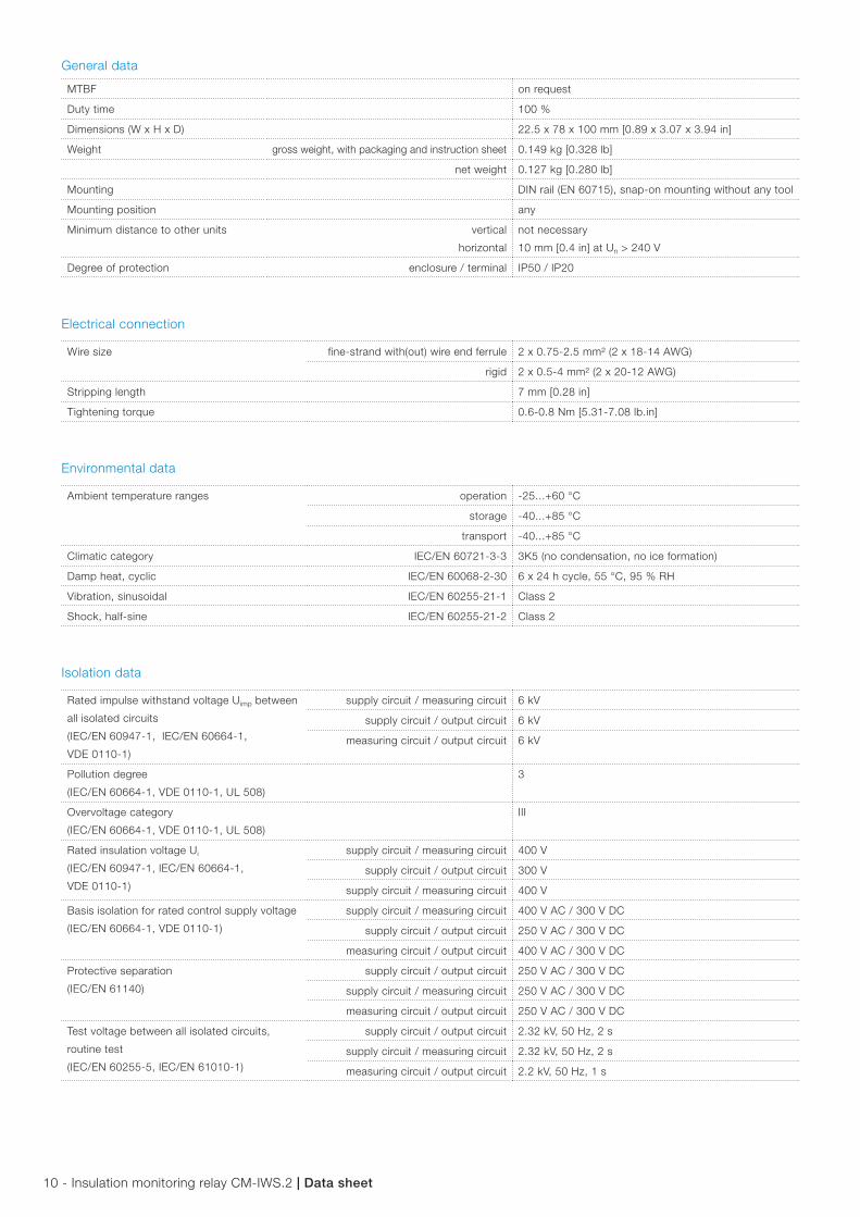
General data
MTBF on request
Duty time 100 %
Dimensions (W x H x D) 22.5 x 78 x 100 mm [0.89 x 3.07 x 3.94 in]
Weight gross weight, with packaging and instruction sheet 0.149 kg [0.328 lb]
net weight 0.127 kg [0.280 lb]
Mounting DIN rail (EN 60715), snap-on mounting without any tool
Mounting position any
Minimum distance to other units vertical
horizontal
not necessary
10 mm [0.4 in] at Un > 240 V
Degree of protection enclosure / terminal IP50 / IP20
Electrical connection
Wire size fine-strand with(out) wire end ferrule 2 x 0.75-2.5 mm² (2 x 18-14 AWG)
rigid 2 x 0.5-4 mm² (2 x 20-12 AWG)
Stripping length 7 mm [0.28 in]
Tightening torque 0.6-0.8 Nm [5.31-7.08 lb.in]
Environmental data
Ambient temperature ranges operation -25...+60 °C
storage -40...+85 °C
transport -40...+85 °C
Climatic category IEC/EN 60721-3-3 3K5 (no condensation, no ice formation)
Damp heat, cyclic IEC/EN 60068-2-30 6 x 24 h cycle, 55 °C, 95 % RH
Vibration, sinusoidal IEC/EN 60255-21-1 Class 2
Shock, half-sine IEC/EN 60255-21-2 Class 2
Isolation data
Rated impulse withstand voltage Uimp between
all isolated circuits
(IEC/EN 60947-1, IEC/EN 60664-1,
VDE 0110-1)
supply circuit / measuring circuit 6 kV
supply circuit / output circuit 6 kV
measuring circuit / output circuit 6 kV
Pollution degree
(IEC/EN 60664-1, VDE 0110-1, UL 508)
3
Overvoltage category
(IEC/EN 60664-1, VDE 0110-1, UL 508)
III
Rated insulation voltage Ui
(IEC/EN 60947-1, IEC/EN 60664-1,
VDE 0110-1)
supply circuit / measuring circuit 400 V
supply circuit / output circuit 300 V
supply circuit / measuring circuit 400 V
Basis isolation for rated control supply voltage
(IEC/EN 60664-1, VDE 0110-1)
supply circuit / measuring circuit 400 V AC / 300 V DC
supply circuit / output circuit 250 V AC / 300 V DC
measuring circuit / output circuit 400 V AC / 300 V DC
Protective separation
(IEC/EN 61140)
supply circuit / output circuit 250 V AC / 300 V DC
supply circuit / measuring circuit 250 V AC / 300 V DC
measuring circuit / output circuit 250 V AC / 300 V DC
Test voltage between all isolated circuits,
routine test
(IEC/EN 60255-5, IEC/EN 61010-1)
supply circuit / output circuit 2.32 kV, 50 Hz, 2 s
supply circuit / measuring circuit 2.32 kV, 50 Hz, 2 s
measuring circuit / output circuit 2.2 kV, 50 Hz, 1 s

Datasheet |Insulation monitoring relay CM-IWS.2 - 11
Standards
Product standard IEC/EN 61557-8, IEC/EN 60255-6
Other standards EN 50178
Low Voltage Directive 2006/95/EC
EMC Directive 2004/108/EC
RoHS Directive 2002/95/EC
Electromagnetic compatibility
Interference immunity to IEC/EN 61000-6-1, IEC/EN 61000-6-2, IEC/EN 61326-2-4
electrostatic discharge IEC/EN 61000-4-2 Level 3, 6 kV / 8 kV
radiated, radio-frequency, electromagnetic field IEC/EN 61000-4-3 Level 3, 10 V/m (1 GHz) / 3 V/m (2 GHz) / 1 V/m (2.7 GHz)
electrical fast transient/burst IEC/EN 61000-4-4 Level 3, 2 kV / 5 kHz
surge IEC/EN 61000-4-5 Level 3, installation class 3, supply circuit and
measuring circuit 1 kV L-L, 2 kV L-earth
conducted disturbances, induced by radio-frequency
fields
IEC/EN 61000-4-6 Level 3, 10 V
voltage dips, short interruptions and voltage variations IEC/EN 61000-4-11 Level 3
harmonics and interharmonics IEC/EN 61000-4-13 Level 3
Interference emission IEC/EN 61000-6-3, IEC/EN 61000-6-4
high-frequency radiated IEC/CISPR 22, EN 50022 Class B
high-frequency conducted IEC/CISPR 22, EN 50022 Class B

12 - Insulation monitoring relay CM-IWS.2 |Datasheet
Technicaldiagrams
Load limits curves
300
200
1008060504030
20
101 2 4 6 10
I A
V
V
0.1 0.2 0.5
2CD
C 2
52 1
94 F
0205
AC load (resistive)
cos ϕ
F
0.5
0.1 0.2 0.3 0.4 0.5 0.6 0.7 0.8 0.9 1.0
0.6
0.7
0.8
0.9
1.0
2CD
C 2
52 1
92 F
0205
Derating factor F at inductive AC load
300
200
1008060504030
20
101 2 4 6 10
I A
V
V
0.1 0.2 0.5
2CD
C 2
52 1
93 F
0205
DC load (resistive)
Switching current [A]
250 Vresistive load
Sw
itchi
ng c
ycle
s
2CD
C 2
52 1
48 F
0206
Contact lifetime
Dimensionaldrawings
in mm and inches
4.31”109.5
102 4.02” 22.5
0.886”
78 3.07
”
5.50.216”
1003.94”
10.039”
2CD
C 2
52 0
31 F
0005
CM-IWS.2 - Insulation monitoring relay

Datasheet |Insulation monitoring relay CM-IWS.2 - 13
Accessories6.
5 62.5
60
1011
.5
20
0.25
6”
2.461”
2.362”
70 2.756”
0.39
4”
0.78
7”
0.45
3”
2CD
C 2
52 1
87 F
0005
ADP.01 - Adapter for screw mounting
203A11 8
0.31
5”
0.787”
2CD
C 2
52 1
86 F
0005
MAR.01 - Marker label
22.5
68.5
73.5
0.886”
2.70
”
0.138”0.275”
front-to-backsize 107 1S
VC
110
000
F0
180
COV.01 - Sealable transparent cover
Furtherdocumentation
Documenttitle Documenttype Documentnumber
Electronic products and relays Technical catalogue 2CDC 110 004 C020x
Instruction sheet Instruction sheet 1SVC 630 550 M0000
You can find the documentation on the internet at www.abb.com/lowvoltage -> Control Products -> Electronic Relays and Controls.
ABB STOTZ-KONTAKT GmbHP. O. Box 10 16 8069006 Heidelberg, GermanyPhone: +49 (0) 6221 7 01-0Fax: +49 (0) 6221 7 01-13 25E-mail: [email protected]
You can find the address of your local sales organisation on the ABB home pagehttp://www.abb.com/contacts -> Low Voltage Products and Systems
Contact us
Note:We reserve the right to make technical changes or modify the contents of this document without prior notice. With regard to purchase orders, the agreed particulars shall prevail. ABB AG does not accept any responsibility whatsoever for potential errors or possible lack of information in this document.
We reserve all rights in this document and in the subject matter and illustrations contained therein. Any reproduction, disclosure to third parties or utilization of its contents – in whole or in parts – is forbidden without prior written consent of ABB AG.
Copyright© 2010 ABB All rights reserved
Do
cum
ent
num
ber
2C
DC
112
149
D02
01 p
rinte
d in
Ger
man
y (0
4/10
)