Embed Size (px)
Citation preview

Comments, suggestions, or questions on this document should be addressed to: Commander, Naval Sea Systems
Command, ATTN: SEA 05S, 1333 Isaac Hull Avenue, SE, Stop 5160, Washington Navy Yard DC 20376-5160 or
emailed to CommandStandards@navy mil, with the subject line “Document Comment”. Since contact information
can change, you may want to verify the currency of this address information using the ASSIST Online database at
https://assist.dla.mil.
AMSC N/A FSC 5640
INCH-POUND
MIL-PRF-32514
12 June 2015
PERFORMANCE SPECIFICATION
INSULATION, ANTI-SWEAT, REFRIGERANT, AND
THERMAL FOAM
Downloaded from http://www.everyspec.com

DEPARTMENT OF THE NAVY
NAVAL SEA SYSTEMS COMMAND
1333 ISAAC HULL AVE SE
WASHINGTON NAVY YARD DC 20376-0001 IN REPLY REFER TO
4121 Ser 05P/119
ii
From: Commander, Naval Sea Systems Command (SEA 05, CHENG)
Subj: CHENG’S INTENT FOR IMPLEMENTATION OF THERMAL FOAM INSULATION
Ref: (a) MIL-PRF-32514, INSULATION, ANTI-SWEAT, REFRIGERANT, AND
THERMAL FOAM
1. Purpose. The NAVSEA Chief Engineer’s (CHENG’s) intent for issuing
reference (a) is to provide a non-proprietary procurement
specification for affordable, easy-to-handle insulation for piping,
machinery, ventilation ducts, and anti-sweat refrigerant lines.
2. Discussion. Reference (a) was written to provide a standardized
military specification that can be used for acquisition by all
activities. Reference (a) also supports procurement commonality by
ensuring that the insulation meets all current applicable
requirements. Affordable, low-toxicity, fire-retardant thermal foam
insulation was originally developed for submarine new construction and
was specified by a proprietary industry specification. Since its
introduction to the Fleet, this insulation, with greatly reduced
flammability and smoke, has been approved for many platforms and is
now widely used for ship and submarine new construction, repair, and
maintenance.
3. Action. NAVSEA encourages all activities to invoke reference (a),
where appropriate, in their ship designs.
4. Point of Contact. For information pertaining to thermal foam
insulation, please contact SEA 05P23, Mr. Dave Owen, commercial
(202) 781-0651, email: [email protected].
L. B. FULLER
By direction
Affixed to: MIL-PRF-32514
Downloaded from http://www.everyspec.com

MIL-PRF-32514
1
This specification is approved for use by all Departments and Agencies of the Department of Defense.
1. SCOPE
1.1 Scope. This specification establishes the requirements for anti-sweat, refrigerant, and thermal foam
insulation (see 6.1 and 6.6.2) for use on piping, pipe components, ventilation ducts, and machinery. This material is
not approved for use on bulkheads, decks, or other surfaces.
1.2 Classification. Insulation is of the following types, grades, classes, and forms, as specified (see 6.2).
1.2.1 Types.
a. Type I: Anti-sweat and refrigerant insulation for piping, pipe components, and machinery (surface ships
and submarines)
b. Type II: Thermal insulation for hot piping applications (180 °F maximum for submarines and 300 °F
maximum for surface ships)
c. Type III: Thermal insulation for ventilation ducts
1.2.2 Grades.
a. Grade A: For unlagged applications
b. Grade B: For lagged applications
1.2.3 Classes.
a. Class 1: -20 to 180 °F maximum operating temperature
b. Class 2: -20 to 300 °F maximum operating temperature
1.2.4 Forms.
a. Form 1: Tubular
b. Form 2: Sheet
2. APPLICABLE DOCUMENTS
2.1 General. The documents listed in this section are specified in sections 3 and 4 of this specification. This
section does not include documents cited in other sections of this specification or recommended for additional
information or as examples. While every effort has been made to ensure the completeness of this list, document
users are cautioned that they must meet all specified requirements of documents cited in sections 3 and 4 of this
specification, whether or not they are listed.
2.2 Government documents.
2.2.1 Specifications, standards, and handbooks. The following specifications, standards, and handbooks form a
part of this document to the extent specified herein. Unless otherwise specified, the issues of these documents are
those cited in the solicitation or contract.
DEPARTMENT OF DEFENSE SPECIFICATIONS
MIL-A-24179 - Adhesive, Flexible Unicellular – Plastic Thermal Insulation
(Copies of this document are available online at http://quicksearch.dla.mil/.)
2.2.2 Other Government documents, drawings, and publications. The following other Government documents,
drawings, and publications form a part of this document to the extent specified herein. Unless otherwise specified,
the issues of these documents are those cited in the solicitation or contract.
Downloaded from http://www.everyspec.com

MIL-PRF-32514
2
NAVAL SEA SYSTEMS COMMAND (NAVSEA) PUBLICATIONS
S9510-AB-ATM-010 - Nuclear Powered Submarine Atmosphere Control Manual
(Copies of the chapter titled “Material Control Program” are available by email request to
CommandStandards@navy mil.)
2.3 Non-Government publications. The following documents form a part of this document to the extent specified
herein. Unless otherwise specified, the issues of these documents are those cited in the solicitation or contract.
ASTM INTERNATIONAL
ASTM C177 - Standard Test Method for Steady-State Heat Flux Measurements and Thermal
Transmission Properties by Means of the Guarded-Hot-Plate Apparatus
ASTM C411 - Standard Test Method for Hot-Surface Performance of High-Temperature Thermal
Insulation
ASTM C421 - Standard Test Method for Tumbling Friability of Preformed Block-Type and
Preformed Pipe-Covering-Type Thermal Insulation
ASTM C447 - Standard Practice for Estimating the Maximum Use Temperature of Thermal
Insulations
ASTM C518 - Standard Test Method for Steady-State Thermal Transmission Properties by Means
of the Heat Flow Meter Apparatus
ASTM C1338 - Standard Test Method for Determining Fungi Resistance of Insulation Materials and
Facings
ASTM D412 - Standard Test Methods for Vulcanized Rubber and Thermoplastic
Elastomers—Tension
ASTM D471 - Standard Test Method for Rubber Property—Effect of Liquids
ASTM D512 - Standard Test Methods for Chloride Ion in Water
ASTM D624 - Standard Test Method for Tear Strength of Conventional Vulcanized Rubber and
Thermoplastic Elastomers
ASTM D1056 - Standard Specification for Flexible Cellular Materials—Sponge or Expanded Rubber
ASTM D1149 - Standard Test Methods for Rubber Deterioration—Cracking in an Ozone Controlled
Environment
ASTM D1179 - Standard Test Methods for Fluoride Ion in Water
ASTM D1246 - Standard Test Method for Bromide Ion in Water
ASTM D1667 - Standard Specification for Flexible Cellular Materials—Poly (Vinyl Chloride) Foam
(Closed-Cell)
ASTM E96 - Standard Test Methods for Water Vapor Transmission of Materials
ASTM E662 - Standard Test Method for Specific Optical Density of Smoke Generated by Solid
Materials
(Copies of these documents are available online at www.astm.org.)
INTERNATIONAL ELECTROCHEMICAL COMMISSION (IEC)
Downloaded from http://www.everyspec.com

MIL-PRF-32514
3
IEC 60754-1 - Test on Gases Evolved During Combustion of Materials from Cables – Part 1:
Determination of the Halogen Acid Gas Content
(Copies of this document are available online at www.iec.ch.)
INTERNATIONAL MARITIME ORGANIZATION (IMO)
IMO A.653(16) - Recommendation on Improved Fire Test Procedures for Surface Flammability of
Bulkhead, Ceiling and Deck Finish Materials
(Copies of this document are available online at www.imo.org/publications.)
INTERNATIONAL ORGANIZATION FOR STANDARDIZATION (ISO)
ISO/IEC 17025 - General Requirements for the Competence of Testing and Calibration Laboratories
(Copies of this document are available online at www.iso.org.)
2.4 Order of precedence. Unless otherwise noted herein or in the contract, in the event of a conflict between the
text of this document and the references cited herein, the text of this document takes precedence. Nothing in this
document, however, supersedes applicable laws and regulations unless a specific exemption has been obtained.
3. REQUIREMENTS
3.1 Qualification. The insulation furnished under this specification shall be products that are authorized by the
qualifying activity for listing on the applicable Qualified Products List (QPL) before contract award (see 4.2 and 6.3).
3.2 Dimension and tolerance. The insulation dimensions shall be as specified (see 6.2). Form 1 tubular material,
up to 65⁄8 inches inside diameter (ID), shall have no seams or chemically bonded joints and shall not be manufactured
from flat sheets. Tubular insulation shall be furnished in straight lengths or coil form as specified (see 6.2). Form 2
sheet material shall be seamless. Unless otherwise specified (see 6.2), tolerances shall be as specified in table I and
4.4.2.
TABLE I. Dimensional tolerance of Type I, II, and III, Form 1 – tubular insulation and Form 2 – sheet insulation.
Form 1 – Tubular
Wall thickness (inches) Length (inches) Inside diameter (inches)
Dimension Tolerance Dimension Tolerance Dimension Tolerance
Up to ¾, inclusive -0 to +⅛ 1/
-1 to +4 Up to ½, inclusive +1⁄16 to +5⁄32
Over ¾ -0 to +3⁄16 -1 to +4 Over ½ to 2½, inclusive +1⁄16 to +3⁄16
Over 2½ +1⁄16 to +5⁄16
Form 2 – Sheet
Thickness (inches) Length and width (inches)
Dimension Tolerance Dimension Tolerance
Up to ¼, inclusive +3⁄32 to -1⁄32 Up to 6, inclusive ±¼
Over ¼ to ½, inclusive +3⁄32 to -1⁄32 Over 6 to 12, inclusive ±3⁄8
Over ½ to 1, inclusive ±3⁄32 Over 12 ±3%
Over 1 ±⅛
NOTE: 1/
Lengths of tubular form or number of sheets shall be as specified (see 6.2).
3.3 Physical requirements. The insulation shall conform to table II and the fire performance requirements of
section 3.4.
Downloaded from http://www.everyspec.com

MIL-PRF-32514
4
TABLE II. Physical requirements.
Insulation properties Requirement
Density, maximum 8.0 lb/ft3
Compression resistance at 25% deflection 2.0 to 6.0 lb/in2
Water absorption, maximum 0.1 lb/ft2
Compression set, maximum 30%
Dimensional change, length, maximum 7%
Oil resistance No shrinkage or swelling more than 2% in width, length, or
thickness
Odor No objectionable odor
Tensile strength, minimum 1/
30 lb/in2
Ultimate elongation, minimum 45%
Tensile strength of cemented joints
Before aging, minimum No bond failure
After aging, minimum (tubular only) No bond failure
Flexibility at 28 °F (initially) No cracking
After heat aging for 7 days at 180 °F
(tubular only) No cracking
Thermal conductivity
At mean temperature 75 °F k-factor,
maximum 0.30 BTU-in/hr sq ft °F
Water vapor permeability, maximum 0.30 perm-inches (perm-in)
Total free halogen content, maximum 250 parts per million (ppm)
Fungi resistance No signs of fungal growth after 30 days
Ozone resistance No signs of cracking or deterioration
Upper temperature limit
Class 1 at 180 °F No softening, collapsing, melting, or dripping
Class 2 at 300 °F No softening, collapsing, melting, or dripping
Mass loss by tumbling <3% after first 10 minutes
<5% after second 10 minutes
NOTE: 1/
If 30 lb/in2 minimum tensile strength cannot be achieved, then the insulation shall exhibit a
minimum tensile strength of 20 lb/in2 and a minimum tear strength of 3.8 lb/in (see 4.4.25).
3.4 Fire performance. Each type, grade, class, and form of insulation to be qualified shall be subjected to the
fire tests specified in this section (see 4.2.4, 4.4.20, and 6.9).
3.4.1 Large-scale pipe insulation corner test (for type I and type II only). The insulation shall be subjected to a
large-scale pipe insulation corner test (see 4.4.20.1). The test shall measure the performance criteria specified in
3.4.1.1 and 3.4.1.2.
Downloaded from http://www.everyspec.com

MIL-PRF-32514
5
3.4.1.1 Flame spread. The flame spread shall be no more than 1 foot of flame spread on horizontal pipe runs.
Additionally, no melting or dripping shall be evident, and no ignition of the target array on the floor of the test
chamber caused by burning insulation shall occur.
3.4.1.2 Heat release rate (HRR). The maximum HRR for pipe insulation shall be 11,384 BTU/min
(200 kilowatts [kW]) not including the HRR of the initiating fuel source (e.g., gas burner).
3.4.2 Large-scale ventilation duct insulation corner test (for type III only). The insulation shall be subjected to
a large-scale ventilation duct insulation corner test (see 4.4.20.2). The test shall measure the performance criteria in
3.4.2.1 and 3.4.2.2.
3.4.2.1 Flame spread. The flame spread shall be no more than 1 foot of flame spread on horizontal duct runs.
Additionally, no melting or dripping shall be evident, and no ignition of the target array on the floor of the test
chamber caused by burning insulation shall occur.
3.4.2.2 HRR. The maximum HRR for duct insulation shall be 11,384 BTU/min (200 kW) not including the
HRR of the initiating fuel source (e.g., gas burner).
3.4.3 Acid gas generation (type I, type II, and type III). Acid gas generation of the insulation shall not exceed
0.25 percent acid gas by weight (see 4.4.20.3).
3.4.4 Surface flammability (type I, type II, and type III). The insulation shall meet the following surface
flammability requirements when tested in accordance with 4.4.20.4:
a. Critical flux at extinguishment (CFE) shall be equal to or greater than 20 kW per square meter (m2).
b. Heat for sustained burning (Qsb) shall be equal to or greater than 1.5 megajoules (MJ)/m2.
c. Total heat release (Qt) shall be less than or equal to 0.7 MJ.
d. Peak HRR (Qp) shall be less than or equal to 4 kW.
e. No melting, dripping, or flaming droplets shall be evident.
3.4.5 Smoke density (type I, type II, and type III). The smoke density of the insulation shall be no greater than
250 when tested in both non-flaming and flaming mode (see 4.4.20.5). No melting, dripping, or flaming droplets
shall be evident.
3.5 Toxicity. When evaluated in accordance with 4.4.21 (the Health Hazard Assessment [the HHA]), the
insulation shall have no adverse effect on the health of personnel when used for its intended purpose (see 4.4.21 and
6.7).
3.6 Off-gassing. The insulation shall be tested for off-gassing in accordance with the requirements of 4.4.22.
The Navy will review the results and assign a usage category. The required usage category is “Permitted” or
“Limited” (see 4.4.22 and 6.8).
3.7 Workmanship. The insulation shall be free of any cuts, tears, seams, slits (Form 2 – sheet only), chemically
bonded joints, or repaired sections. The insulation shall be clean and free of dirt, foreign material, and embedded
particles. The insulation cell size shall be uniform and the insulation shall be free of large voids. The color of the
insulation shall be uniform throughout the material (see 4.4.23).
3.8 Finish. Unless otherwise specified (see 6.2), Form 1 – tubular and Form 2 – sheet shall have at least one
natural skin surface (see 4.4.24). For tubular, when only one natural skin surface is provided, the natural skin shall
be on the outer diameter (OD) of the tube. For sheets, the natural skin surface shall be a major surface and shall not
include the edges or ends. Natural skin is inherent to the material itself and shall not include external applications of
coatings or distinctive outer layers of material.
Downloaded from http://www.everyspec.com

MIL-PRF-32514
6
3.9 Marking. Form 1 – tubular shall be marked to include the Iron Pipe Size (IPS), the wall thickness, and the
manufacturer’s designation. Form 2 – sheet shall be marked to include the thickness and the manufacturer’s
designation. Unless otherwise specified (see 6.2), the manufacturer’s designation and the thickness shall be legibly
marked on one side of each sheet in at least one place, with characters of not less than ¼-inch height, and on tubes,
repeated at intervals not exceeding 30 inches.
3.10 Recycled, recovered, or environmentally preferable, or biobased materials. Recycled, recovered,
environmentally preferable, or biobased materials should be used to the maximum extent possible, provided that the
material meets or exceeds the operational and maintenance requirements, and promotes economically advantageous
life cycle costs.
4. VERIFICATION
4.1 Classification of inspections. The inspection requirements specified herein are classified as follows:
a. Qualification inspection (see 4.2).
b. Conformance inspection (see 4.3).
4.2 Qualification inspection. Qualification inspection shall be performed on insulation, shall include the
examination of 4.4, and shall be as specified in table III.
4.2.1 Qualification samples. The qualification samples shall be taken from a production lot of material and
shall consist of enough tubular form or sheet form insulation to perform all tests as required in table III.
4.2.2 Qualified thickness. Insulation shall only be qualified up to the thickness that successfully passes all fire
tests. The maximum qualified thickness shall be specified on the QPL.
4.2.3 Fire testing equivalency. Insulation that passes the fire test acceptance criteria for vent duct insulation
(see 3.4.2) shall also satisfy the fire test acceptance criteria for pipe insulation (see 3.4.1) without the need to
conduct fire testing on pipe insulation, for equal or less insulation thickness, provided the vent duct insulation and
pipe insulation materials are identical.
4.2.4 Fire testing provisions. All fire tests specified in this document shall be conducted by an independent
testing laboratory that is accredited to ISO/IEC 17025. Accreditation shall be obtained from a recognized
accreditation body such as American Association for Laboratory Accreditation (A2LA) or International Code
Council’s International Accreditation Services (IAS). The scope of accreditation shall include specific flammability
and fire tests required for qualification. All other fire test provisions shall be as specified (see 6.2 and 6.9).
Downloaded from http://www.everyspec.com

MIL-PRF-32514
7
TABLE III. Qualification inspection.
Inspection Requirement Test method
Dimensions 3.2 4.4.2
Density 3.3 4.4.3
Compression resistance at 25% deflection (lb/in2) 3.3 4.4.4
Water absorption 3.3 4.4.5
Compression set 3.3 4.4.6
Dimensional change, length 3.3 4.4.7
Oil resistance 3.3 4.4.8
Odor 3.3 4.4.9
Tensile strength 3.3 4.4.10
Ultimate elongation 3.3 4.4.10
Tensile strength of cemented joints
Before aging 3.3 4.4.11.1
After aging, Form 1 – tubular (only) 3.3 4.4.11.2
Flexibility at 28 °F (initial) 3.3 4.4.12.1
After heat aging for 7 days at 180 °F,
Form 1 – tubular (only) 3.3 4.4.12.2
Thermal conductivity 3.3 4.4.13
Water vapor permeability 3.3 4.4.14
Total free halogen content 3.3 4.4.15
Fungi resistance 3.3 4.4.16
Ozone resistance 3.3 4.4.17
Upper temperature limit, Class 1 and Class 2 3.3 4.4.18
Mass loss by tumbling 3.3 4.4.19
Fire performance 3.4 4.4.20
Toxicity 3.5 4.4.21
Off-gassing, Type I and Type III (only) 3.6 4.4.22
Workmanship 3.7 4.4.23
Finish 3.8 4.4.24
4.2.5 Periodic retention of qualification. At intervals of not more than 3 years after initial qualification,
inspection for retention of qualification shall be performed on insulation and shall include the examinations
specified in table IV (see 6.3).
Downloaded from http://www.everyspec.com

MIL-PRF-32514
8
TABLE IV. Recertification testing.
Inspection Requirement Test method
Density 3.3 4.4.3
Compression resistance 3.3 4.4.4
Compression set 3.3 4.4.6
Dimensional change 3.3 4.4.7
Tensile strength 3.3 4.4.10
Ultimate elongation 3.3 4.4.10
Thermal conductivity 3.3 4.4.13
Water vapor permeability 3.3 4.4.14
Surface flammability 3.4.4 4.4.20.4
Smoke density 3.4.5 4.4.20.5
Workmanship 3.7 4.4.23
Finish 3.8 4.4.24
4.2.6 Change approval. A change in material, production processes, or production equipment used in the
manufacture of these insulation products, which have been qualified, shall require written approval of NAVSEA.
Incorporation of any changes that have not been so approved shall require requalification of the item in question.
4.3 Conformance inspection. Conformance inspection shall be conducted for each lot and for all master batch
production as specified in 4.3.1, 4.3.2, and 4.3.3. Government representatives may witness conformance
inspections.
4.3.1 Lot. For purposes of sampling, a lot for examination and testing shall consist of sheets and tubes
produced in one plant under the same conditions and offered for delivery at one time. The unit of product shall
consist of one sheet or one length of tubing, as applicable. A random sample of material shall be selected from each
lot in accordance with table V.
Downloaded from http://www.everyspec.com

MIL-PRF-32514
9
TABLE V. Sampling for lot examination and testing.
Lot size (sheets and tubes) Sample size
2 to 25 1
26 to 50 2
51 to 90 4
91 to 150 6
151 to 280 10
281 to 500 11
501 to 1200 15
1201 to 3200 18
3201 to 10,000 22
10,001 to 35,000 29
4.3.2 Master batch. A master batch shall consist of a quantity of finished compounded rubber of not more than
30,000 pounds, mixed at one time, and ready to be extruded.
4.3.2.1 Master batch production. For purposes of examination and testing, master batch production shall
consist of all lots of sheets and tubes produced in one plant from one master batch.
4.3.2.2 Sampling for master batch production. One random sample of finished sheet material, sufficient to
complete examination and testing, shall be selected from each lot containing sheets. At least one finished sheet
sample shall be produced and tested for each master batch. For conformance tests, master batch production shall be
as specified in 4.3.2.1.
4.3.3 Conformance tests. Samples selected in accordance with 4.3.1 and 4.3.2 shall be subjected to the tests
specified in table VI and shall conform to the requirements in table II.
Downloaded from http://www.everyspec.com

MIL-PRF-32514
10
TABLE VI. Conformance testing.
Inspection Lot Master batch
production
Dimensions 4.4.2 4.4.2
Density 4.4.3 4.4.3
Tensile strength N/A 4.4.10
Ultimate elongation N/A 4.4.10
Thermal conductivity N/A 4.4.13
Workmanship 4.4.23 4.4.23
Finish 4.4.24 4.4.24
Tear strength (if required; see table II) N/A 4.4.25
4.4 Test methods.
4.4.1 Conditioning procedures. Unless otherwise specified herein, specimens shall be conditioned in an
atmosphere of 73.4±1.8 °F and 50±4 percent relative humidity for at least 24 hours.
4.4.2 Dimensional measurements of test specimen.
4.4.2.1 Results. The average results of not less than three measurements shall be recorded.
4.4.2.2 Form 1 – tubular. The length shall be measured with any measuring device graduated in at least 1⁄16-inch increments. Care shall be taken not to distort the insulation material. Thickness and ID measurements
shall be measured with any measuring device graduated in at least 1⁄32-inch increments. Three thickness
measurements shall be taken and distributed around the circumference of the tube.
4.4.2.3 Form 2 – sheet. The length and width shall be measured with a measuring device graduated in at
least 1⁄16-inch increments. The insulation material shall not distort. Thickness shall be determined in accordance
with ASTM D1056 using three measurements equally spaced over the specimens.
4.4.3 Density. The density of the insulation shall be determined in accordance with ASTM D1667.
4.4.4 Compression resistance. Compression resistance shall be determined in accordance with
ASTM D1667, except that the deflection-load rate shall be not greater than 2 inches per minute
(0.85 millimeters per second).
4.4.5 Water absorption.
4.4.5.1 Specimens. Test specimens shall be 4 by 4 inches square or semi-cylindrical sections (tubular
form cut in half longitudinally), 6 inches long in the thickness furnished. The specimen may have the skin on
top and bottom, outer and inner surfaces, or on only one of these surfaces, as specified (see 6.2).
4.4.5.2 Procedure. Specimens shall be immersed in distilled water that has equilibrated at 70 to 80 °F,
2 inches below the surface of the water, and subjected to a vacuum of 25 inches of mercury for 3 minutes. The
vacuum shall be released and the specimens shall remain immersed for 3 minutes at atmospheric pressure. The
specimens shall then be removed and stood on end to drain for 10 minutes and then shall be blotted lightly with
paper towels. Values of each of the three specimens shall be calculated and recorded in terms of pounds of
water gain per square foot (lb/ft2) of skinless surface.
Downloaded from http://www.everyspec.com

MIL-PRF-32514
11
4.4.6 Compression set.
4.4.6.1 Specimens. The specimens shall have parallel top and bottom surfaces that shall be at right angles
to the side surfaces. The specimen shall be cylindrical or rectangular. The dimension across the top shall be
not less than the thickness, and the top shall be not less than 1 in2 in area.
4.4.6.2 Procedure. The compression set of the insulation shall be determined in accordance with
ASTM D1667, except that the maximum dimension across the top of the specimen shall be not greater than
16 in2 in area.
4.4.7 Dimensional change.
4.4.7.1 Specimens. Test specimens shall consist of 32- by 3-inch pieces in the thickness of the sheet
supplied or tubular sections 32 inches long by the thickness furnished.
4.4.7.2 Procedure. Bench marks, approximately 30 inches apart, shall be placed on the center line of the
specimens about 1 inch from the ends, and the distance shall be measured to the nearest 0.01 inch. The
specimens shall be placed lengthwise on a piece of wooden board in an oven equipped with air circulation at
200±3 °F for 7 days. The specimen shall then be removed from the oven, conditioned for a minimum of
2 hours at 73.5±5 °F, and the distance between the bench marks shall be measured. The dimensional change
shall be expressed in percent of the original length.
4.4.8 Oil resistance.
4.4.8.1 Specimens. The test specimens shall be not less than 1 inch by 1 inch by the thickness of
insulation.
4.4.8.2 Procedure. The length, width, and thickness of each specimen shall be measured before each is
immersed in No. 3 oil in accordance with ASTM D471 for 70 hours at 73±4 °F. The specimens shall then be
removed, blotted with filter paper, and checked for changes in dimensions.
4.4.9 Odor. The odor of sheets and tubular forms at room temperature shall be determined by sniffing.
The odor of tubular specimens that are being subjected to the aging test as specified in 4.4.12.2 shall be
determined at the end of the first and seventh day by sniffing.
4.4.10 Tensile strength and ultimate elongation.
4.4.10.1 Specimens. The test specimens shall be ¼±1⁄32 inch thick by ½ inch wide. Die A in accordance
with ASTM D412 shall be used.
4.4.10.2 Procedure. The tensile strength and ultimate elongation shall be determined in accordance with
ASTM D412, with the following exceptions:
a. A 0.5-ounce weight shall be used on the presser foot for measurement of thickness.
b. The number of test specimens and test values shall be in accordance with table V.
c. All values shall be recorded.
d. Median values shall not apply.
4.4.11 Tensile strength of cemented joints.
4.4.11.1 Before aging. As specified in 4.4.10.1, test specimens shall be cut in half at the center of the
constricted portion and cemented together with adhesive qualified to the requirements of MIL-A-24179
(see 3.3). The adhesive shall be allowed to air dry for at least 24 hours. The strength of the cemented joint
shall be determined as specified in 4.4.10. The number of specimens shall be as specified in 4.4.10.2.
Downloaded from http://www.everyspec.com
MIL-PRF-32514
12
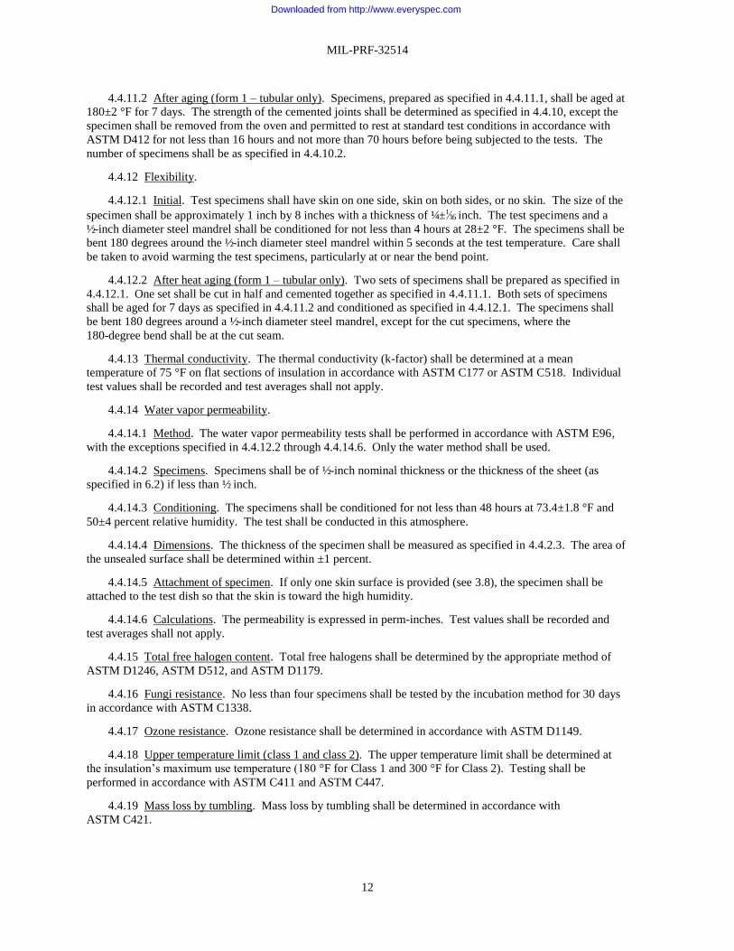
4.4.11.2 After aging (form 1 – tubular only). Specimens, prepared as specified in 4.4.11.1, shall be aged at
180±2 °F for 7 days. The strength of the cemented joints shall be determined as specified in 4.4.10, except the
specimen shall be removed from the oven and permitted to rest at standard test conditions in accordance with
ASTM D412 for not less than 16 hours and not more than 70 hours before being subjected to the tests. The
number of specimens shall be as specified in 4.4.10.2.
4.4.12 Flexibility.
4.4.12.1 Initial. Test specimens shall have skin on one side, skin on both sides, or no skin. The size of the
specimen shall be approximately 1 inch by 8 inches with a thickness of ¼±1⁄16 inch. The test specimens and a
½-inch diameter steel mandrel shall be conditioned for not less than 4 hours at 28±2 °F. The specimens shall be
bent 180 degrees around the ½-inch diameter steel mandrel within 5 seconds at the test temperature. Care shall
be taken to avoid warming the test specimens, particularly at or near the bend point.
4.4.12.2 After heat aging (form 1 – tubular only). Two sets of specimens shall be prepared as specified in
4.4.12.1. One set shall be cut in half and cemented together as specified in 4.4.11.1. Both sets of specimens
shall be aged for 7 days as specified in 4.4.11.2 and conditioned as specified in 4.4.12.1. The specimens shall
be bent 180 degrees around a ½-inch diameter steel mandrel, except for the cut specimens, where the
180-degree bend shall be at the cut seam.
4.4.13 Thermal conductivity. The thermal conductivity (k-factor) shall be determined at a mean
temperature of 75 °F on flat sections of insulation in accordance with ASTM C177 or ASTM C518. Individual
test values shall be recorded and test averages shall not apply.
4.4.14 Water vapor permeability.
4.4.14.1 Method. The water vapor permeability tests shall be performed in accordance with ASTM E96,
with the exceptions specified in 4.4.12.2 through 4.4.14.6. Only the water method shall be used.
4.4.14.2 Specimens. Specimens shall be of ½-inch nominal thickness or the thickness of the sheet (as
specified in 6.2) if less than ½ inch.
4.4.14.3 Conditioning. The specimens shall be conditioned for not less than 48 hours at 73.4±1.8 °F and
50±4 percent relative humidity. The test shall be conducted in this atmosphere.
4.4.14.4 Dimensions. The thickness of the specimen shall be measured as specified in 4.4.2.3. The area of
the unsealed surface shall be determined within ±1 percent.
4.4.14.5 Attachment of specimen. If only one skin surface is provided (see 3.8), the specimen shall be
attached to the test dish so that the skin is toward the high humidity.
4.4.14.6 Calculations. The permeability is expressed in perm-inches. Test values shall be recorded and
test averages shall not apply.
4.4.15 Total free halogen content. Total free halogens shall be determined by the appropriate method of
ASTM D1246, ASTM D512, and ASTM D1179.
4.4.16 Fungi resistance. No less than four specimens shall be tested by the incubation method for 30 days
in accordance with ASTM C1338.
4.4.17 Ozone resistance. Ozone resistance shall be determined in accordance with ASTM D1149.
4.4.18 Upper temperature limit (class 1 and class 2). The upper temperature limit shall be determined at
the insulation’s maximum use temperature (180 °F for Class 1 and 300 °F for Class 2). Testing shall be
performed in accordance with ASTM C411 and ASTM C447.
4.4.19 Mass loss by tumbling. Mass loss by tumbling shall be determined in accordance with
ASTM C421.
Downloaded from http://www.everyspec.com

MIL-PRF-32514
13
4.4.20 Fire performance. The insulation shall be tested as specified in 3.4 and in accordance with the
following test standards:
4.4.20.1 Large-scale pipe insulation corner test. See Appendix A for test procedure and description of test
apparatus.
4.4.20.2 Large-scale ventilation duct insulation corner test. See Appendix B for test procedure and
description of test apparatus.
4.4.20.3 Acid gas generation (type I, type II, and type III). Acid gas generation shall be determined by the
test method IEC 60754-1, test on gases evolved during combustion (see 3.4.3). Test results shall be expressed
as a percent by weight equivalent.
4.4.20.4 Surface flammability (type I, type II, and type III). Surface flammability shall be determined in
accordance with IMO A.653(16) (see 3.4.4).
4.4.20.5 Smoke density (type I, type II, and type III). Smoke density shall be determined in accordance
with ASTM E662 (see 3.4.5).
4.4.21 Toxicity. An HHA shall be conducted to ensure conformance to 3.5, as required by the qualifying
activity. The Navy and Marine Corps Public Health Center (NMCPHC) will evaluate the insulation using the
administrative HHA data provided by the manufacturer/distributor to the NMCPHC.
4.4.22 Off-gassing. The insulation shall be tested for off-gassing at a Government approved testing
facility in accordance with S9510-AB-ATM-010 chapter titled “Material Control Program” (see 3.6 and 6.8).
4.4.23 Workmanship. The insulation shall be visually inspected for the presence of cuts, tears, seams, slits
(Form 2 –sheet only), chemically bonded joints, or repaired sections. The insulation shall also be inspected for
cleanliness and dirt, foreign material, and embedded particles. Insulation cell size shall be visually inspected
for uniformity and the presence of large voids and uniformity of color throughout the material (see 3.7).
4.4.24 Finish (form 1 – tubular and form 2 – sheet). Unless otherwise specified (see 6.2), the insulation
shall have at least one natural skin surface (see 3.8).
4.4.25 Tear strength. Tear strength shall be determined in accordance with ASTM D624. Die C in
accordance with ASTM D624 shall be used.
5. PACKAGING
5.1 Packaging. For acquisition purposes, the packaging requirements shall be as specified in the contract
or order (see 6.2). When packaging of materiel is to be performed by DoD or in-house contractor personnel,
these personnel need to contact the responsible packaging activity to ascertain packaging requirements.
Packaging requirements are maintained by the Inventory Control Point’s packaging activities within the
Military Service or Defense Agency, or within the military service’s system commands. Packaging data
retrieval is available from the managing Military Department’s or Defense Agency’s automated packaging files,
CD-ROM products, or by contacting the responsible packaging activity.
6. NOTES
(This section contains information of a general or explanatory nature that may be helpful, but is not
mandatory.)
6.1 Intended use. The insulation covered by this specification is intended for anti-sweat, refrigerant, and
thermal insulation only and may be used in either sheet or tubular form. The insulation is intended for piping
systems or ventilation duct applications operating at temperatures from -20 to 300 °F. This insulation has low
thermal conductivity and is serviceable at operating temperatures. This material is not approved for use on
bulkheads, decks, or other surfaces.
Downloaded from http://www.everyspec.com

MIL-PRF-32514
14
6.2 Acquisition requirements. Acquisition documents should specify the following:
a. Title, number, and date of this specification.
b. Type, grade, class, and form required (see 1.2). When ordering tubular form, specify pipe size or
tubing ID and insulation thickness (see 1.2 and 3.2).
c. Dimensions as required and tolerance, if different from table I and 4.4.2 (see 3.2 and 4.4.14.2).
d. Number of sheets or length of tubing or coil (see table I and 3.2).
g. If two surface skins are required (see 3.8).
h. Marking and special marking required (see 3.9).
i. Additional fire testing provisions (see 4.2.4 and 6.9).
j. Location of skin (see 4.4.5.1).
k. Water vapor permeability test specimen thickness (see 4.4.14.2).
l. Packaging requirements (see 5.1).
m. Material safety data sheets, when required (see 6.5).
n. When a certificate of compliance is required (see 6.10).
6.3 Qualification. With respect to products requiring qualification, awards will be made only for products
which are, at the time of award of contract, qualified for inclusion in QPL-32514 whether or not such products
have actually been so listed by that date. The attention of the contractors is called to these requirements, and
manufacturers are urged to arrange to have the products that they propose to offer to the Federal Government
tested for qualification in order that they may be eligible to be awarded contracts or orders for the products
covered by this specification. Information pertaining to qualification of products may be obtained from
Commander, Naval Sea Systems Command, ATTN: SEA05S, 1333 Isaac Hull Avenue, SE, Stop 5160,
Washington Navy Yard DC 20376-5160 or emailed to [email protected]. An online listing of
products qualified to this specification may be found in the Qualified Products Database (QPD) at
https://assist.dla.mil.
6.4 Supersession data. This specification supersedes MIL-P-15280J, dated 19 December 1988, for
shipboard insulation applications as specified in relevant design, repair and installation documents and
drawings. MIL-P-15280 material is no longer permitted for use as shipboard insulation. Additionally, this
document includes requirements for higher temperature (300 °F) thermal insulation.
6.5 Material safety data sheets. When specified (see 6.2), contracting officers will identify those activities
requiring copies of completed Material Safety Data Sheets (MSDS) prepared in accordance with
FED-STD-313. In order to obtain the MSDS, Federal Acquisition Regulation (FAR) clause 52.223-3 must be
in the contract.
6.6 Definitions.
6.6.1 Configuration. A combination of insulation materials and components that requires a specific
method or sequence of installation, including glass cloth lagging applied to protect insulation or insulation
systems from damage on board ship.
6.6.2 Insulation. A homogeneous base material (insulating material) exhibiting uniform properties
throughout its thickness or length.
6.7 Toxicity evaluation. The NMCPHC requires sufficient information to permit an HHA of the product.
Upon completion of the HHA, a copy will be provided by the NMCPHC to the Government for evaluation.
Downloaded from http://www.everyspec.com

MIL-PRF-32514
15
6.8 Material certification. Materials to be installed in submarines are to be controlled to prevent off-
gassing, which contaminates the submarine’s atmosphere and can result in health hazards to personnel or
deleterious effects on machinery. These controls are administered through the Submarine Material Control
Program, which is described in the Nuclear Powered Submarine Atmosphere Control Manual,
S9510-AB-ATM-010 chapter titled “Material Control Program.” Under the Submarine Material Control
Program, all materials considered for use on submarines require certification and assignment of a usage
category. Under the certification process, candidate materials are selected by Navy activities or contractors,
and a request for certification is submitted to the Naval Sea Systems Command, SEA 05S, 1333 Isaac Hull
Avenue, SE, Stop 5160, Washington Navy Yard, DC 20376-5160 or emailed to
CommandStandards@navy mil. The certification request is accompanied by detailed information, including
descriptions of the material, method of application, usage, and storage. A chemical analysis is conducted,
which is normally accomplished through off-gas testing. The off-gas test is required to be conducted in a
Government approved laboratory designated by the preparing activity. Information pertaining to this test
requirement may be obtained from the Naval Sea Systems Command, SEA 05S, 1333 Isaac Hull Avenue, SE,
Stop 5160, Washington Navy Yard, DC 20376-5160 or emailed to [email protected]. Based on
the chemical analysis results, a usage category is assigned to the material defining whether, and to what extent,
the material may be used on submarines.
6.9 Additional fire testing provisions. NAVSEA reserves the right to witness the tests and perform any of
the tests set forth herein where such testing is deemed necessary to assure compliance to prescribed
requirements of the qualification tests (see 6.2). Since the insulation may be lagged post-delivery with a Navy
approved lagging for fire protection purposes, once approved to Grade B, the insulation will only be installed
with the same lagging as qualified.
6.10 Certification. Consideration should be given to including certificates of compliance with each
shipment of insulation. When specified (see 6.2), certificates should indicate successful completion of the
individual tests of the conformance inspection.
6.11 Subject term (key word) listing.
Ducts
Fire performance
Flexibility
Piping
Sheet
Tubular
Water vapor permeability
Downloaded from http://www.everyspec.com

MIL-PRF-32514
APPENDIX A
16
PIPE INSULATION CORNER TEST
A.1 SCOPE
A.1.1 Scope. This Appendix is intended to provide requirements for a standard room corner fire test that can
be used to evaluate pipe insulation materials. This Appendix is a mandatory part of the specification. The
information contained herein is intended for compliance.
A.1.2 Applicability. The specific performance characteristics to be evaluated are as follows:
a. Flame spread
b. HRR
c. Combustion gas generation
d. Smoke optical density
A.2 APPLICABLE DOCUMENTS
A.2.1 General. The documents listed in this section are specified in Appendix A of this specification. This
section does not include documents cited in other sections of this specification or recommended for additional
information or as examples. While every effort has been made to ensure the completeness of this list, document
users are cautioned that they must meet all specified requirements of documents cited in Appendix A of this
specification, whether or not they are listed.
A.2.2 Non-Government publications. The following documents form a part of this document to the extent
specified herein. Unless otherwise specified, the issues of these documents are those cited in the solicitation or
contract.
NATIONAL FIRE PROTECTION ASSOCIATION (NFPA)
NFPA 286 - Standard Methods of Fire Tests for Evaluating Contribution of Wall and Ceiling
Interior Finish to Room Fire Growth
(Copies of this document are available online at www.nfpa.org.)
A.3 TEST COMPARTMENT
A.3.1 Test compartment. The test compartment shall be located inside a larger burn facility to negate the
effects of environmental conditions such as wind and rain. The facility shall be capable of providing sufficient
combustion air for the test. The fire tests shall be conducted inside a steel compartment that is used to simulate a
typical shipboard space. Figures A-1 and A-2 provide an isometric sketch and plan drawing of the compartment.
The interior dimensions of the compartment shall be 10 feet by 10 feet by 8 feet high with a single vent 2.45 feet
wide by 6.5 feet high. Any single dimension of the compartment shall not vary by more than ±1 inch, and any
single dimension of the vent shall not vary by more than ±0.5 inch. The compartment shall be constructed of
0.25-inch thick steel plate. Reinforcing stiffeners may be used; however, they shall not interfere with the installation
of the test pipes.
Downloaded from http://www.everyspec.com

MIL-PRF-32514
APPENDIX A
17
FIGURE A-1. CBD steel compartment for use in pipe insulation tests.
Downloaded from http://www.everyspec.com

Downloaded from http://www.everyspec.com

MIL-PRF-32514
APPENDIX A
19
FIGURE A-3. Conceptual drawing of pipe insulation test set-up.
FIGURE A-4. Section view of pipe arrangement.
Downloaded from http://www.everyspec.com

MIL-PRF-32514
APPENDIX A
20
FIGURE A-5. Typical elevation of pipe set-up.
A.4.2 Test pipe supports. The pipe runs shall be supported using a 0.5-inch steel angle welded vertically to the
ceiling of the compartment. Horizontal supports for the piping shall be attached to the vertical segments using
0.25-inch bolts. The pipe runs shall be secured in place at each support using wire tied to the cross supports. The
support locations and details are provided on figures A-4 and A-6. The geometric center of the vertical run shall be
centered over the gas burner.
Downloaded from http://www.everyspec.com

MIL-PRF-32514
APPENDIX A
21
FIGURE A-6. Location of horizontal pipe supports.
A.5 IGNITION SOURCE
A.5.1 Ignition source. The ignition source shall be a gas fired burner in accordance with NFPA 286, with
modified fuel bed surface dimensions of 15 inches by 15 inches by 6 inches high. The burner shall use C.P. grade
propane as the fuel. The gas piping shall be installed inside the burner box and the box shall then be filled with
materials to allow for the diffusion of the gas. Figure A-3 provides a view of the burner. The gas burner shall be
placed in the test corner area such that it is 2 inches from the adjacent wall surfaces, with the top surface of the
burner located 14 inches above the floor. The burner shall be supported on concrete blocks or equivalent.
The HRRs for the burner shall be as shown below:
Test time (minutes) HRR (kW)
0 – 3 50
3 – 15 160
A.6 INSTRUMENTATION
A.6.1 Layout. A general layout of the instrumentation is shown on figure A-7.
Downloaded from http://www.everyspec.com

MIL-PRF-32514
APPENDIX A
22
A.6.2 Temperatures. A vertical thermocouple tree shall be located in the center of the compartment. The tree
shall consist of 16 thermocouples located every 6 inches below the ceiling. A second thermocouple tree shall be
located in the vertical centerline of the vent. This tree shall consist of 13 thermocouples located at the following
distances below the top of the vent opening:
a. 1 inch
b. 6 inches
c. 12 inches
d. 18 inches
e. 24 inches
f. 30 inches
g. 36 inches
h. 42 inches
i. 48 inches
j. 54 inches
k. 60 inches
l. 66 inches
m. 72 inches
All of the thermocouples shall be a maximum of 24 gauge, Type K thermocouples. Each thermocouple shall
have a bare bead.
A.6.3 Flame spread. Along with visual observations, flame spread may be assessed using thermocouples along
the entire simulated pipe array. Spaced 2 feet on center, the thermocouples shall be installed along both the vertical
and horizontal portions of the piping assembly. All of the thermocouples shall be a maximum of 24 gauge, Type K
thermocouples. Each thermocouple shall have a bare bead.
Downloaded from http://www.everyspec.com

MIL-PRF-32514
APPENDIX A
23
FIGURE A-7. Plan view of instrumentation layout.
A.6.4 Air flow. Not used.
A.6.5 Gas concentrations. Gas analyzers shall provide a continuous monitoring of oxygen (O2), carbon
monoxide (CO), and carbon dioxide (CO2) concentrations of gases in the exhaust hood. The oxygen concentration
shall be measured via a paramagnetic oxygen analyzer while the CO and CO2 concentrations shall be measured via
infrared process analyzers.
A.6.6 Smoke. Three laser/photocells or equivalent instruments shall be used to assess the smoke production
within the compartment. The path length shall be 3.3 feet, and they shall be placed horizontally at 3.84 feet,
5.35 feet, and 6.56 feet above the deck and near the center of compartment.
Downloaded from http://www.everyspec.com

MIL-PRF-32514
APPENDIX A
24
A.6.7 Target array. In order to assess the potential for the pipe insulation materials to cause secondary
ignitions due to melting, dripping, or falling pieces, a target array of excelsior shall be placed on the deck of the
compartment beginning 1 foot away from the edge of the gas burner, under the horizontal pipe run, and extend the
full length of the horizontal pipe run.
A.6.8 Weight loss. In order to assess the amount of insulation consumed during the test, each pipe shall be
weighed prior to insulation being applied, weighed in its final insulated test configuration, and weighed at the
conclusion of the test.
A.6.9 HRR. The HRR of the fire inside the compartment shall be measured. A hood/exhaust system shall be
used to capture all of the exhaust gases exiting from the room doorway. The exhaust system shall be instrumented
so as to measure the HRR based on oxygen depletion calorimetry.
A.6.10 Data collection. Data obtained during the test shall be recorded at intervals not to exceed 5 seconds.
A.7 INSTALLATION OF TEST MATERIALS
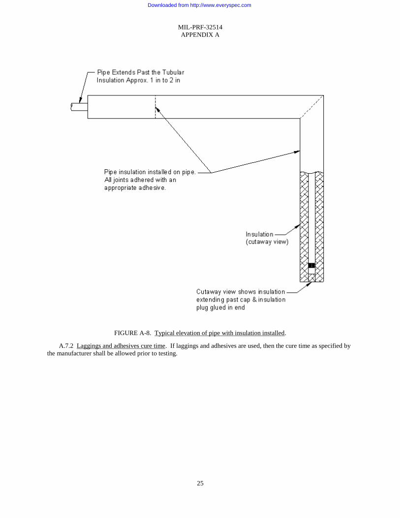
A.7.1 Installation of test materials. The pipe insulation shall be installed on the 0.5-inch pipes. The insulation
on the vertical riser section shall extend past the threaded end cap, and a plug or cap of the same insulation shall be
adhered in place over the pipe cap. All butt joints and seams shall be sealed using the appropriate adhesives.
Figure A-8 shows an elevation view of a typical installed insulation.
Downloaded from http://www.everyspec.com
MIL-PRF-32514
APPENDIX A
25
FIGURE A-8. Typical elevation of pipe with insulation installed.
A.7.2 Laggings and adhesives cure time. If laggings and adhesives are used, then the cure time as specified by
the manufacturer shall be allowed prior to testing.
Downloaded from http://www.everyspec.com

MIL-PRF-32514
APPENDIX A
26
A.8 TEST PROCEDURES
A.8.1 Environmental. The environmental conditions inside the test compartment just prior to test shall be 50 to
90 °F (10 to 32 °C).
A.8.2 Procedures. The following test procedures shall be followed:
a. Install test pipe insulations.
b. Verify placement and operation of instrumentation, video, and position of target array.
c. Verify environmental conditions.
d. Clean the sand burner.
e. Position gas burner in test corner.
f. Begin 2-minute baseline data collection.
g. At 2-minute mark, ignite the gas burner.
h. Continue the test until either:
(1) 15 minutes of burn time have elapsed (17 minutes total) or
(2) Test must be ended due to safety conditions.
Downloaded from http://www.everyspec.com

MIL-PRF-32514
APPENDIX B
27
DUCT INSULATION CORNER TEST
B.1 SCOPE
B.1.1 Scope. This Appendix is intended to provide requirements for a standard room corner fire test that can
be used to evaluate ventilation duct insulation materials that are applied to the exterior surfaces of ventilation ducts.
This Appendix is a mandatory part of the specification. The information contained herein is intended for
compliance.
B.1.2 Applicability. The specific performance characteristics to be evaluated are as follows:
a. Flame spread
b. HRR
c. Combustion gas generation
d. Smoke optical density
B.2 TEST COMPARTMENT
B.2.1 Test compartment. The test compartment shall be located inside a larger burn facility to negate the
effects of environmental conditions such as wind and rain. The facility shall be capable of providing sufficient
combustion air for the test. The fire tests shall be conducted inside a steel compartment that is used to simulate a
typical shipboard space. Figure B-1 provides an isometric sketch of the compartment. The interior dimensions of
the compartment shall be 10 feet by 10 feet by 8 feet high with a single vent 2.45 feet wide by 6.5 feet high. Any
single dimension of the compartment shall not vary by more than ±1 inch and any single dimension of the vent shall
not vary by more than ±0.5 inch. The compartment shall be constructed of 0.25-inch thick steel plate. Reinforcing
stiffeners may be used; however, they should not interfere with the installation of the test ducts.
FIGURE B-1. Steel compartment for use in duct insulation test.
Downloaded from http://www.everyspec.com

MIL-PRF-32514
APPENDIX B
28
B.3 TEST DUCT CONFIGURATION
B.3.1 Test duct configuration. The base ventilation ducts to be tested shall be pre-fabricated and shall be of
non-watertight construction using galvanized sheet steel with a thickness of 0.0635 inches. The duct configuration
shall consist of two base ducts, one with a 6-inch by 15-inch cross section and one with an 18-inch by 15-inch cross
section. Each duct shall be 55 inches in length for the vertical portion and 85 inches in length for the horizontal
portion. The bottom of the vertical portion of the ducts shall be welded closed using the same metal as the ducts.
The ends of the horizontal portion of the ducts that are the most remote from the fire source shall remain open.
Ducting that provides transition from the vertical to horizontal shall be welded.
B.3.2 Insulation thickness. Vent duct insulation material shall be applied at a thickness of 1 inch or at an actual
shipboard thickness (see B.6).
B.3.3 Installation configuration. The insulated duct configurations shall be installed inside the test
compartment in a manner that provides a vertical run of ducting in the area above the ignition source. As this
vertical run meets the overhead, the run changes into a horizontal duct run across the underside of the compartment
overhead. The finished sides of the insulated duct configuration shall be 16 inches from the left wall, 14 inches
from the back wall, and 4 inches from the overhead. There shall be a 2-inch separation between the finished sides of
the two insulated ducts. The finished bottom of the vertical ducts shall be 8 inches above the top surface of the
burner. Figures B-2, B-3, and B-4 provide sketches of this arrangement.
Downloaded from http://www.everyspec.com

MIL-PRF-32514
APPENDIX B
29
FIGURE B-2. Plan view – duct and burner arrangement.
Downloaded from http://www.everyspec.com

MIL-PRF-32514
APPENDIX B
30
FIGURE B-3. Side view – duct and burner arrangement.
Downloaded from http://www.everyspec.com

MIL-PRF-32514
APPENDIX B
31
FIGURE B-4. Drawing of duct insulation test set-up.
B.3.4 Test duct supports. The duct runs shall be supported using a 1-inch steel angle welded vertically to the
ceiling of the compartment or equivalent supports. Horizontal supports for the ducts shall be a 1-inch steel angle
attached to the vertical segments using bolts. The support locations and details are provided on figure B-4.
B.4 IGNITION SOURCE
B.4.1 Ignition source. The ignition source shall be a gas fired burner with fuel bed surface dimensions of
23 inches by 34 inches by 12 inches high. The burner shall use C.P. grade propane as the fuel. The gas piping shall
be installed inside the burner box, and the box shall then be filled with materials to allow for the diffusion of the gas.
Figure B-5 provides a sketch of the burner. The burner shall be positioned on the floor of the test compartment such
that the 23-inch dimension is 12 inches from the back wall and the 34-inch dimension is 16 inches from the left wall.
These spacings shall be measured from the interior surface of the wall to the edge of the fuel bed of the burner.
Downloaded from http://www.everyspec.com

MIL-PRF-32514
APPENDIX B
32
FIGURE B-5. Ignition burner.
Downloaded from http://www.everyspec.com

MIL-PRF-32514
APPENDIX B
33
B.4.2 HRRs. The HRRs for the burner shall be as shown below:
Test time (minutes) HRR (kW)
0-5 100
5-10 150
10-20 200
B.5 INSTRUMENTATION
B.5.1 Instrumentation. A general layout of the instrumentation is shown on figure B-6.
Downloaded from http://www.everyspec.com

MIL-PRF-32514
APPENDIX B
34
FIGURE B-6. Plan view of instrumentation layout.
B.5.2 Temperatures. A vertical thermocouple tree shall be located in the center of the compartment. The tree
shall consist of 16 thermocouples located every 6 inches below the ceiling. Temperatures shall also be measured
along the vertical and the horizontal runs of the ducts (see B.5.3). All of the thermocouples shall be a maximum of
24 gauge, Type K thermocouples. Each thermocouple shall have a bare bead.
Downloaded from http://www.everyspec.com

MIL-PRF-32514
APPENDIX B
35
B.5.3 Flame spread. Along with visual observations, flame spread may be assessed using thermocouples along
the entire simulated duct array. The thermocouples shall be installed along both the vertical and horizontal portions
of the duct assembly as shown on figures B-6 and B-7. All of the thermocouples shall be a maximum of 24 gauge,
Type K thermocouples. Each thermocouple shall have a bare bead.
FIGURE B-7. Vertical trees – TS X and TL X.
B.5.4 Gas concentrations. Gas analyzers shall provide a continuous monitoring of O2, CO, and CO2
concentrations of gases in the exhaust hood. The oxygen concentration shall be measured via a paramagnetic
oxygen analyzer while the CO and CO2 concentrations shall be measured via infrared process analyzers.
B.5.5 Smoke. Three light photocells or equivalent instruments shall be used to assess the smoke production
within the compartment. The path length shall be 3.3 feet, and the light photocells shall be placed horizontally at
3.84 feet, 5.35 feet, and 6.56 feet above the deck and near the center of the compartment. One light photocell
assembly or equivalent instruments shall also be used to assess the smoke production within the exhaust duct.
Downloaded from http://www.everyspec.com

MIL-PRF-32514
APPENDIX B
36
B.5.6 Target array. In order to assess the potential for the duct insulation materials to cause secondary ignitions
due to melting, dripping, or falling pieces, a target array of wood excelsior shall be placed on the deck of the
compartment beginning 1 foot away from the edge of the gas burner, under the horizontal duct run, and extend the
full length and width of the horizontal portion of the duct configuration.
B.5.7 Weight loss. In order to assess the amount of insulation consumed during the test, each duct shall be
weighed prior to insulation being applied, weighed in its final insulated test configuration, and weighed at the
conclusion of the test.
B.5.8 HRR. The HRR of the fire inside the compartment shall be measured. A hood exhaust system shall be
used to capture all of the exhaust gases exiting from the room doorway. The exhaust system shall be instrumented
so as to measure the HRR based on oxygen depletion calorimetry.
B.5.9 Data collection. Data obtained during the test shall be recorded at intervals not to exceed 5 seconds.
B.6 INSTALLATION OF TEST MATERIALS
B.6.1 Installation of test materials. The duct insulation shall be installed on both ducts. The insulation shall
also be installed on the bottom of the vertical riser section. All butt joints and seams shall be sealed using the
appropriate adhesives. Figure B-8 shows an elevation view of a typical installed insulation. The duct insulation
shall be installed in accordance with vendor recommended practice.
FIGURE B-8. Typical elevation of duct with insulation installed.
Downloaded from http://www.everyspec.com

MIL-PRF-32514
APPENDIX B
37
B.6.2 Laggings and adhesives cure time. If laggings and adhesives are used, then the cure time as specified by
the manufacturer shall be allowed prior to testing.
B.7 TEST PROCEDURES
B.7.1 Environmental. The environmental conditions inside the test compartment just prior to test shall be 50 to
90 °F (10 to 32 °C).
B.7.2 Procedures. The following test procedures shall be followed:
a. Clean the sand burner.
b. Verify placement of gas burner.
c. Install the test ducts.
d. Verify placement and operation of instrumentation, video, and position of target array.
e. Verify environmental conditions.
f. Begin 2-minute baseline data collection.
g. At 2-minute mark, ignite gas burner.
h. At 20 minutes of burn time (22 minutes total), shut off the gas burner.
i. If flaming is noted on the test ducts after the burner is secured, continue video and data collection until all
flaming has ceased or 10 minutes have elapsed, whichever occurs first.
j. The test may be ended at an earlier time due to safety considerations.
Downloaded from http://www.everyspec.com

MIL-PRF-32514
38
Custodians: Preparing activity:
Army – MI Navy – SH
Navy – SH (Project 5640-2012-006)
Air Force – 99
DLA – IS
Review activities:
Army – CE
Navy – AS
Air Force – 03, 84
Civil agency:
GSA – FAS
NOTE: The activities listed above were interested in this document as of the date of this document. Since
organizations and responsibilities can change, you should verify the currency of the information above using the
ASSIST Online database at https://assist.dla.mil.
Downloaded from http://www.everyspec.com


![Blood, Sweat & Tears - [Book] the Best of Blood, Sweat & Tears](https://img.pdfslide.us/doc/110x75/577c780e1a28abe0548e8be9/blood-sweat-tears-book-the-best-of-blood-sweat-tears.jpg)