Embed Size (px)
Citation preview
INSTRUMENTED IMPACT TESTING OF INLINE SKATES
Dodd Grande K2 Corporation Vashon, WA
William Avery
Cannon Engineering Greenwater, WA
Elvis Cepuš and Anoush Poursartip
Department of Metals and Materials Engineering The University of British Columbia
Vancouver, BC
ABSTRACT
A recently released DIN standard requires inline skates to be “skateable” after being subjected to a number of tests, including an impact load at 135 J for adult skates and 90 J for youth skates. Impact testing for the DIN standard is performed using a pendulum device mounted in a steel frame. Currently, there is little understanding of the correlation between the forces subjected on inline skates during DIN testing and actual skating. This paper presents the results of tests designed to (a) measure the loads and loading rates obtained by the DIN test method, (b) to identify the effects of certain equipment and experimental variables on these results, and (c) correlate the DIN test method with skate impacts performed by human subjects. To this purpose, for the DIN standard tests the impact plate was instrumented with a force transducer, the pendulum with a laser displacement sensor, and the skate with an accelerometer. For the human subject tests, similar instrumentation was used. Skate designs with both aluminum and discontinuous glass fiber composite frames were used. For the DIN standard tests, a two peak load-time response is observed, with the second (and larger) peak load being in excess of 9.2 kN for the 135 Joule impact event, with an event duration of about 30 ms. The effect of impact tower constraints and response, skate configuration and boot fixation are seen to be substantial. Furthermore, the human subject tests show a noticeably different behavior, with essentially a single peak load-time response with a peak load of 8.4 kN and an event duration of about 5 ms.
KEY WORDS: Impact Response, Testing/Evaluation, Applications-Leisure/Recreation
1. INTRODUCTION
Since approximately 1997 a standard test method, DIN 33944 [1], has been used for the testing of inline skates. This standard establishes a set of individual tests, which together constitute the DIN test for inline skates. This test is used primarily to evaluate skates for durability and is used by manufacturers, skating magazines and others as a measure of skate quality. The DIN standard includes general guidelines for skate designs as well as specifications for a number of tests and requirements for these tests. In particular, a pendulum impact test that is defined in the DIN standard has found wide applicability as a standard method of testing inline skates for strength and durability. The DIN impact test consists of a pendulum impact tower, with an inline skate fitted to the end of the pendulum. The impact test can be performed in several configurations: head on impact to the front wheel, 45 degree impact to the front wheel, impact to the brake stopper and distributed impact to the bottom of the skate wheels. This paper is limited to the impact case in which the front wheel of an inline skate is subjected to a frontal impact. The major objectives of the work presented here were to (a) measure the loads and loading rates obtained by the DIN test method, (b) to identify the effects of certain equipment and experimental variables on these results, and (c) correlate the DIN test method with skate impacts performed by human subjects. A thorough understanding of the DIN test method, and its relationship to skate response when worn by a user, will hopefully lead to better design, simpler component tests, and finally improvement in the standard test methodology.
2. EXPERIMENTAL PROCEDURE
2.1 Impact Tower and Instrumentation
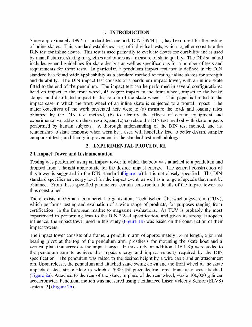
Testing was performed using an impact tower in which the boot was attached to a pendulum and dropped from a height appropriate for the desired impact energy. The general construction of this tower is suggested in the DIN standard (Figure 1a) but is not closely specified. The DIN standard specifies an energy level for the impact event, as well as a range of speeds that must be obtained. From these specified parameters, certain construction details of the impact tower are thus constrained.
There exists a German commercial organization, Technischer Überwachungsverein (TUV), which performs testing and evaluation of a wide range of products, for purposes ranging from certification in the European market to magazine evaluations. As TUV is probably the most experienced in performing tests to the DIN 33944 specification, and given its strong European influence, the impact tower used in this study (Figure 1b) was based on the construction of their impact towers.
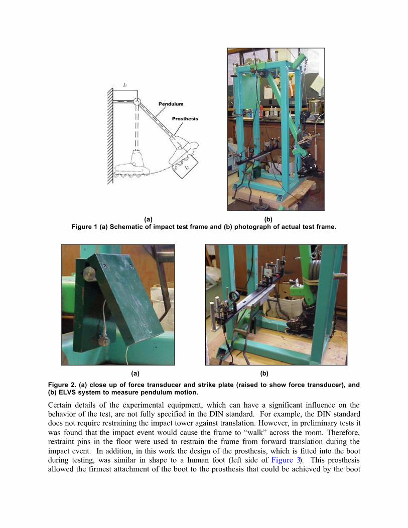
The impact tower consists of a frame, a pendulum arm of approximately 1.4 m length, a journal bearing pivot at the top of the pendulum arm, prosthesis for mounting the skate boot and a vertical plate that serves as the impact target. In this study, an additional 16.1 Kg were added to the pendulum arm to achieve the impact energy and impact velocity required by the DIN specification. The pendulum was raised to the desired height by a wire cable and an attachment pin. Upon release, the pendulum and attached skate swing down and the front wheel of the skate impacts a steel strike plate to which a 5000 lbf piezoelectric force transducer was attached (Figure 2a). Attached to the rear of the skate, in place of the rear wheel, was a 100,000 g linear accelerometer. Pendulum motion was measured using a Enhanced Laser Velocity Sensor (ELVS) system [2] (Figure 2b).
(a) (b)
Figure 1 (a) Schematic of impact test frame and (b) photograph of actual test frame.
(a) (b)
Figure 2. (a) close up of force transducer and strike plate (raised to show force transducer), and (b) ELVS system to measure pendulum motion.
Certain details of the experimental equipment, which can have a significant influence on the behavior of the test, are not fully specified in the DIN standard. For example, the DIN standard does not require restraining the impact tower against translation. However, in preliminary tests it was found that the impact event would cause the frame to “walk” across the room. Therefore, restraint pins in the floor were used to restrain the frame from forward translation during the impact event. In addition, in this work the design of the prosthesis, which is fitted into the boot during testing, was similar in shape to a human foot (left side of Figure 3). This prosthesis allowed the firmest attachment of the boot to the prosthesis that could be achieved by the boot
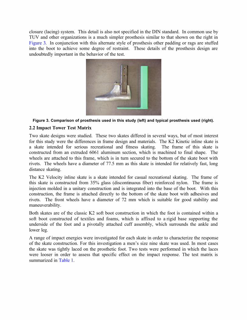
closure (lacing) system. This detail is also not specified in the DIN standard. In common use by TUV and other organizations is a much simpler prosthesis similar to that shown on the right in Figure 3. In conjunction with this alternate style of prosthesis other padding or rags are stuffed into the boot to achieve some degree of restraint. These details of the prosthesis design are undoubtedly important in the behavior of the test.
Figure 3. Comparison of prosthesis used in this study (left) and typical prosthesis used (right).
2.2 Impact Tower Test Matrix
Two skate designs were studied. These two skates differed in several ways, but of most interest for this study were the differences in frame design and materials. The K2 Kinetic inline skate is a skate intended for serious recreational and fitness skating. The frame of this skate is constructed from an extruded 6061 aluminum section, which is machined to final shape. The wheels are attached to this frame, which is in turn secured to the bottom of the skate boot with rivets. The wheels have a diameter of 77.5 mm as this skate is intended for relatively fast, long distance skating.
The K2 Velocity inline skate is a skate intended for casual recreational skating. The frame of this skate is constructed from 35% glass (discontinuous fiber) reinforced nylon. The frame is injection molded in a unitary construction and is integrated into the base of the boot. With this construction, the frame is attached directly to the bottom of the skate boot with adhesives and rivets. The front wheels have a diameter of 72 mm which is suitable for good stability and maneuverability.
Both skates are of the classic K2 soft boot construction in which the foot is contained within a soft boot constructed of textiles and foams, which is affixed to a rigid base supporting the underside of the foot and a pivotally attached cuff assembly, which surrounds the ankle and lower leg.
A range of impact energies were investigated for each skate in order to characterize the response of the skate construction. For this investigation a men’s size nine skate was used. In most cases the skate was tightly laced on the prosthetic foot. Two tests were performed in which the laces were looser in order to assess that specific effect on the impact response. The test matrix is summarized in Table 1.
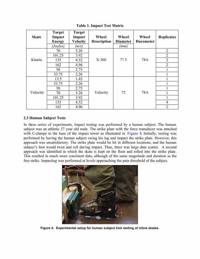
Table 1. Impact Test Matrix
Target Impact Energy
Target Impact Velocity
Wheel
Diameter
Skate
(Joules) (m/s)
Wheel
Description (mm)
Wheel
Durometer
Replicates
70 3.26 2 101.25 3.92 2
135 4.52 2 162 4.96 2 50 2.75 1
Kinetic
33.75 2.26
X-360
77.5
78A
1 13.5 1.43 1 33.75 2.26 1
50 2.75 1 70 3.26 1
101.25 3.92 1 135 4.52 4
Velocity
162 4.96
Velocity
72
78A
2
2.3 Human Subject Tests
In these series of experiments, impact testing was performed by a human subject. The human subject was an athletic 27 year old male. The strike plate with the force transducer was attached with C-clamps to the base of the impact tower as illustrated in Figure 4. Initially, testing was performed by having the human subject swing his leg and impact the strike plate. However, this approach was unsatisfactory. The strike plate would be hit in different locations, and the human subject’s foot would twist and roll dur ing impact. Thus, there was large data scatter. A second approach was identified in which the skate is kept on the floor and rolled into the strike plate. This resulted in much more consistent data, although of the same magnitude and duration as the free strike. Impacting was performed at levels approaching the pain threshold of the subject.
Figure 4. Experimental setup for human subject kick testing of inline skates.
3. RESULTS
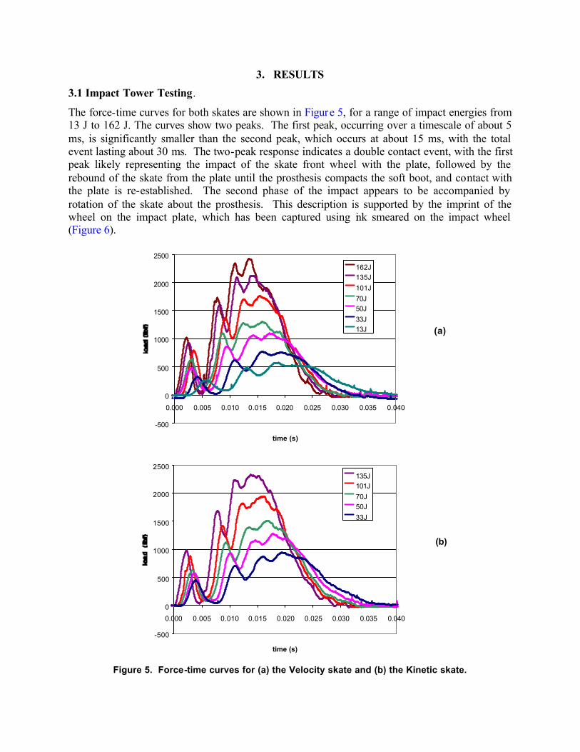
3.1 Impact Tower Testing.
The force-time curves for both skates are shown in Figure 5, for a range of impact energies from 13 J to 162 J. The curves show two peaks. The first peak, occurring over a timescale of about 5 ms, is significantly smaller than the second peak, which occurs at about 15 ms, with the total event lasting about 30 ms. The two-peak response indicates a double contact event, with the first peak likely representing the impact of the skate front wheel with the plate, followed by the rebound of the skate from the plate until the prosthesis compacts the soft boot, and contact with the plate is re-established. The second phase of the impact appears to be accompanied by rotation of the skate about the prosthesis. This description is supported by the imprint of the wheel on the impact plate, which has been captured using ink smeared on the impact wheel (Figure 6).
-500
0
500
1000
1500
2000
2500
0.000 0.005 0.010 0.015 0.020 0.025 0.030 0.035 0.040
time (s)
162J135J
101J
70J50J
33J13J (a)
-500
0
500
1000
1500
2000
2500
0.000 0.005 0.010 0.015 0.020 0.025 0.030 0.035 0.040
time (s)
135J101J
70J50J
33J
(b)
Figure 5. Force-time curves for (a) the Velocity skate and (b) the Kinetic skate.
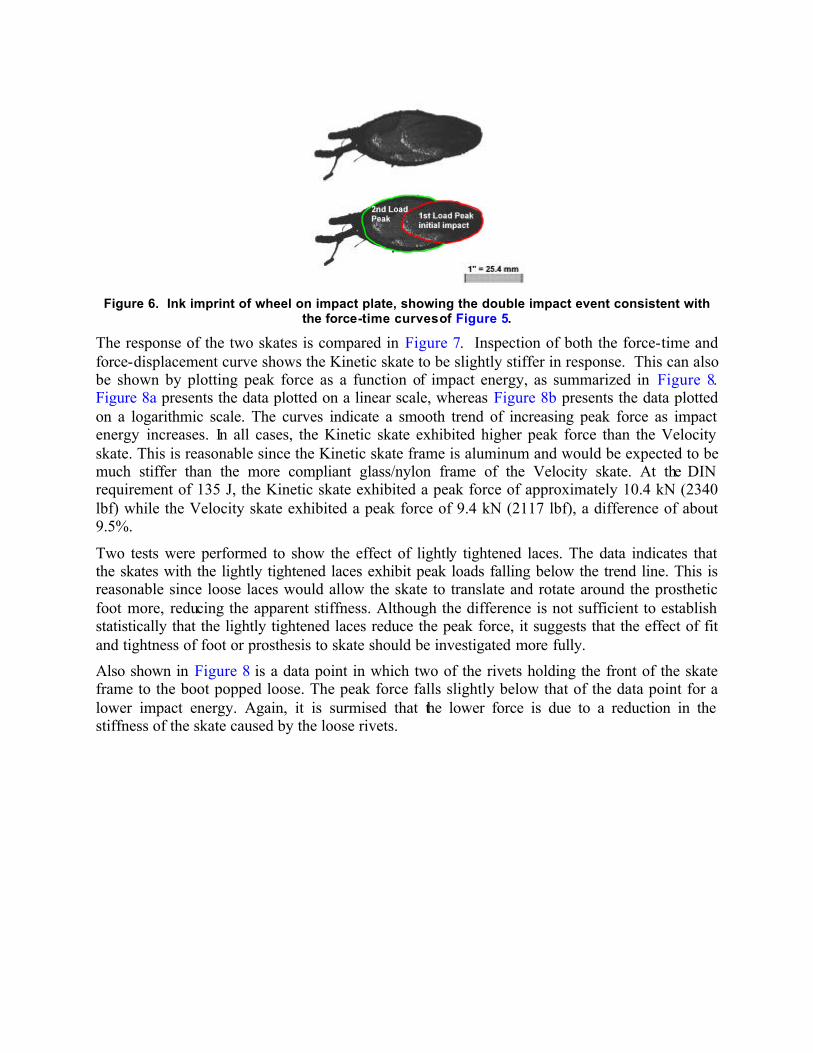
Figure 6. Ink imprint of wheel on impact plate, showing the double impact event consistent with
the force-time curves of Figure 5.
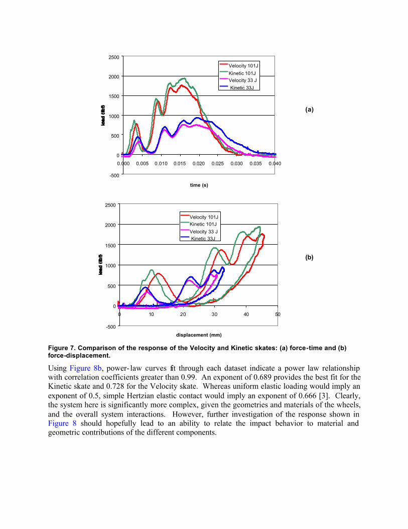
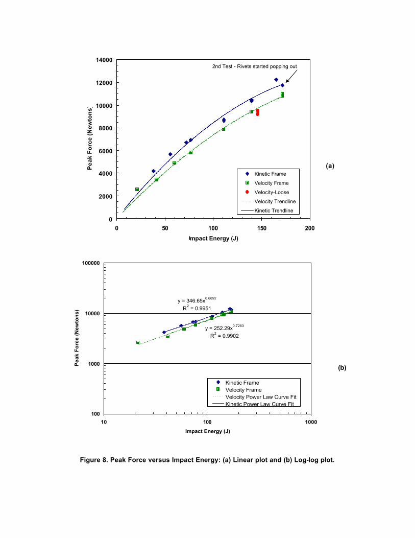
The response of the two skates is compared in Figure 7. Inspection of both the force-time and force-displacement curve shows the Kinetic skate to be slightly stiffer in response. This can also be shown by plotting peak force as a function of impact energy, as summarized in Figure 8. Figure 8a presents the data plotted on a linear scale, whereas Figure 8b presents the data plotted on a logarithmic scale. The curves indicate a smooth trend of increasing peak force as impact energy increases. In all cases, the Kinetic skate exhibited higher peak force than the Velocity skate. This is reasonable since the Kinetic skate frame is aluminum and would be expected to be much stiffer than the more compliant glass/nylon frame of the Velocity skate. At the DIN requirement of 135 J, the Kinetic skate exhibited a peak force of approximately 10.4 kN (2340 lbf) while the Velocity skate exhibited a peak force of 9.4 kN (2117 lbf), a difference of about 9.5%.
Two tests were performed to show the effect of lightly tightened laces. The data indicates that the skates with the lightly tightened laces exhibit peak loads falling below the trend line. This is reasonable since loose laces would allow the skate to translate and rotate around the prosthetic foot more, reducing the apparent stiffness. Although the difference is not sufficient to establish statistically that the lightly tightened laces reduce the peak force, it suggests that the effect of fit and tightness of foot or prosthesis to skate should be investigated more fully.
Also shown in Figure 8 is a data point in which two of the rivets holding the front of the skate frame to the boot popped loose. The peak force falls slightly below that of the data point for a lower impact energy. Again, it is surmised that the lower force is due to a reduction in the stiffness of the skate caused by the loose rivets.
-500
0
500
1000
1500
2000
2500
0.000 0.005 0.010 0.015 0.020 0.025 0.030 0.035 0.040
time (s)
Velocity 101J
Kinetic 101JVelocity 33 J
Kinetic 33J
(a)
-500
0
500
1000
1500
2000
2500
0 10 20 30 40 50
displacement (mm)
Velocity 101JKinetic 101J
Velocity 33 J Kinetic 33J
(b)
Figure 7. Comparison of the response of the Velocity and Kinetic skates: (a) force-time and (b) force-displacement.
Using Figure 8b, power- law curves fit through each dataset indicate a power law relationship with correlation coefficients greater than 0.99. An exponent of 0.689 provides the best fit for the Kinetic skate and 0.728 for the Velocity skate. Whereas uniform elastic loading would imply an exponent of 0.5, simple Hertzian elastic contact would imply an exponent of 0.666 [3]. Clearly, the system here is significantly more complex, given the geometries and materials of the wheels, and the overall system interactions. However, further investigation of the response shown in Figure 8 should hopefully lead to an ability to relate the impact behavior to material and geometric contributions of the different components.
0
2000
4000
6000
8000
10000
12000
14000
0 50 100 150 200
Impact Energy (J)
Pea
k F
orc
e (N
ewto
ns)
Kinetic Frame
Velocity Frame
Velocity-Loose
Velocity Trendline
Kinetic Trendline
2nd Test - Rivets started popping out
(a)
y = 252.29x0.7283
R2 = 0.9902
y = 346.65x0.6892
R2 = 0.9951
100
1000
10000
100000
10 100 1000
Impact Energy (J)
Pea
k F
orc
e (N
ewto
ns)
Kinetic FrameVelocity FrameVelocity Power Law Curve FitKinetic Power Law Curve Fit
(b)
Figure 8. Peak Force versus Impact Energy: (a) Linear plot and (b) Log-log plot.

3.2 Human Subject Test Results
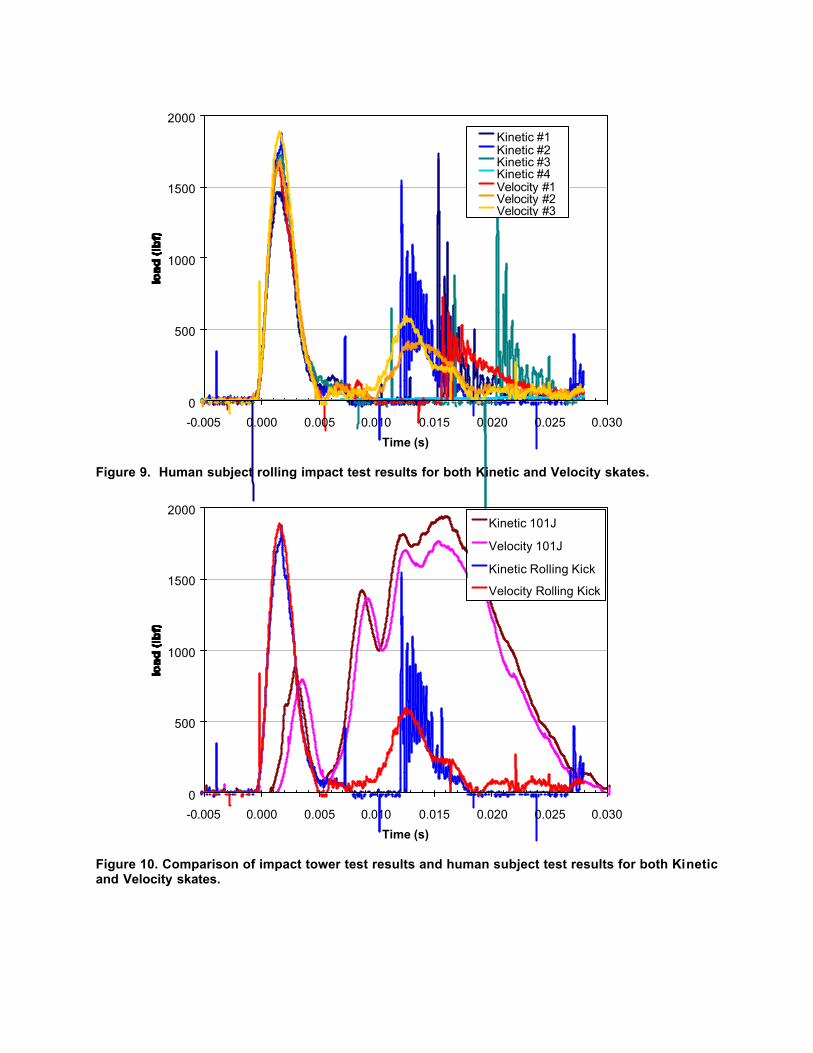
Force-time results from the rolling kick tests are presented in Figure 9. The curves for both skate types show similar behavior. Both exhibit a single peak response over a time interval of about 5 ms. Peak force values ranged from a minimum of 7255 N to a maximum of 8406 N for the seven tests performed, with an average peak force of 7776 N with a COV of 5.8%. The COV can be considered low for such an experiment. Thus, it is reasonable to conclude that the rolling kick method makes differentiation between skate designs relatively difficult. The result is probably dominated by the kicking style of the human subject.
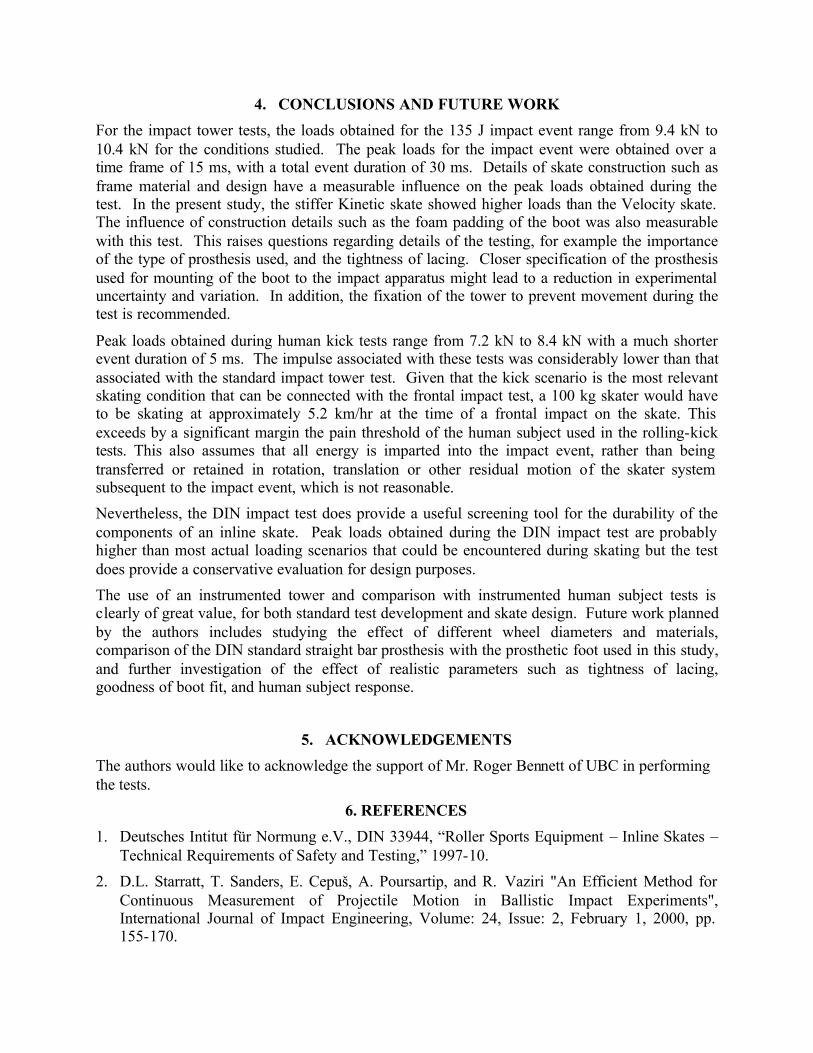
The human subject test results are compared with the 101 J instrumented impact tower test results in Figure 10. A major difference is that the human subject tests reach the peak load value during a 5 ms event, whereas the impact tower tests have an event duration of 30 ms, with a double peak response. In addition, the 135J impact tower tests resulted in peak loads exceeding those from the kick impacts by about 20-33%. Recalling that the human subject kick tests were extreme enough to reach the pain threshold of the human subject, this suggests that the DIN standard may be more severe than impact events which are observed in service. An impact energy of approximately 101 J may be more representative, if the event duration difference can be accounted for.
The human subject tests were performed without the ELVS sensor to measure displacement. As a result, energy values are not available. However, it is still possible to calculate the impulse, which had a maximum value of 29.2 Nm. This compares with an impulse value of 145 Nm for the 135 J impact tower test. Assuming a 100 kg skater, the impact tower test is equivalent to a 1.45 m/s, 5.2 km/hour event, whereas the human subject tests are equivalent to a 0.29 m/s, 1 km/hour event. Given that the pain threshold of the human subject was achieved at the much lower speed, it is not clear whether the impact tower test is thus comparable.
Furthermore, it is not clear why it is desirable to avoid failure in the skate, rather than to desire a controlled and energy absorbing failure in the skate under an overload condition. Conceivably, with a controlled and energy absorbing failure in the skate under overload conditions, the force, impulse, and energy transmitted to the skater would be minimized. The issue of the durability of the skate would then have to be addressed with a test that would be representative of a multiple impact requirement at much lower energy or impulse levels.
0
500
1000
1500
2000
-0.005 0.000 0.005 0.010 0.015 0.020 0.025 0.030
Time (s)
Kinetic #1Kinetic #2Kinetic #3Kinetic #4Velocity #1Velocity #2Velocity #3
Figure 9. Human subject rolling impact test results for both Kinetic and Velocity skates.
0
500
1000
1500
2000
-0.005 0.000 0.005 0.010 0.015 0.020 0.025 0.030
Time (s)
Kinetic 101J
Velocity 101J
Kinetic Rolling Kick
Velocity Rolling Kick
Figure 10. Comparison of impact tower test results and human subject test results for both Kinetic and Velocity skates.
4. CONCLUSIONS AND FUTURE WORK
For the impact tower tests, the loads obtained for the 135 J impact event range from 9.4 kN to 10.4 kN for the conditions studied. The peak loads for the impact event were obtained over a time frame of 15 ms, with a total event duration of 30 ms. Details of skate construction such as frame material and design have a measurable influence on the peak loads obtained during the test. In the present study, the stiffer Kinetic skate showed higher loads than the Velocity skate. The influence of construction details such as the foam padding of the boot was also measurable with this test. This raises questions regarding details of the testing, for example the importance of the type of prosthesis used, and the tightness of lacing. Closer specification of the prosthesis used for mounting of the boot to the impact apparatus might lead to a reduction in experimental uncertainty and variation. In addition, the fixation of the tower to prevent movement during the test is recommended.
Peak loads obtained during human kick tests range from 7.2 kN to 8.4 kN with a much shorter event duration of 5 ms. The impulse associated with these tests was considerably lower than that associated with the standard impact tower test. Given that the kick scenario is the most relevant skating condition that can be connected with the frontal impact test, a 100 kg skater would have to be skating at approximately 5.2 km/hr at the time of a frontal impact on the skate. This exceeds by a significant margin the pain threshold of the human subject used in the rolling-kick tests. This also assumes that all energy is imparted into the impact event, rather than being transferred or retained in rotation, translation or other residual motion of the skater system subsequent to the impact event, which is not reasonable.
Nevertheless, the DIN impact test does provide a useful screening tool for the durability of the components of an inline skate. Peak loads obtained during the DIN impact test are probably higher than most actual loading scenarios that could be encountered during skating but the test does provide a conservative evaluation for design purposes.
The use of an instrumented tower and comparison with instrumented human subject tests is clearly of great value, for both standard test development and skate design. Future work planned by the authors includes studying the effect of different wheel diameters and materials, comparison of the DIN standard straight bar prosthesis with the prosthetic foot used in this study, and further investigation of the effect of realistic parameters such as tightness of lacing, goodness of boot fit, and human subject response.
5. ACKNOWLEDGEMENTS
The authors would like to acknowledge the support of Mr. Roger Bennett of UBC in performing the tests.
6. REFERENCES
1. Deutsches Intitut für Normung e.V., DIN 33944, “Roller Sports Equipment – Inline Skates – Technical Requirements of Safety and Testing,” 1997-10.
2. D.L. Starratt, T. Sanders, E. Cepuš, A. Poursartip, and R. Vaziri "An Efficient Method for Continuous Measurement of Projectile Motion in Ballistic Impact Experiments", International Journal of Impact Engineering, Volume: 24, Issue: 2, February 1, 2000, pp. 155-170.

3. Zukas, J.A., Nicholas, T., Swift, H.F., Greszczuk, L.B., Curran, D.R., Impact Dynamics, John Wiley & Sons, New York, 1982, pp. 55-93.