Embed Size (px)
Citation preview

Reaffirm
ANSI/IS
A M E R I C A N N A T I O N A L S T A N D A R D
Copyright The Instrumentation, Systems, and Automation Society Provided by IHS under license with ISA No reproduction or networking permitted without license from IHS
A–S5.1–1984 (R1992)
Instrumentation Symbolsand Identification
ed 13 July 1992
Licensee=Technip Abu Dabhi/5931917101 Not for Resale, 02/12/2006 05:58:16 MST
--``,`,`,,,,`,,,,`,```,``````,`-`-`,,`,,`,`,,`---

Copyright 1984 by the Instrument Society of America. All rights reserved. Printed in the UnitedStates of America. No part of this publication may be reproduced, stored in a retrieval system, ortransmitted in any form or by any means (electronic, mechanical, photocopying, recording, orotherwise), without the prior written permission of the publisher.
ISA67 Alexander DriveP.O. Box 12277Research Triangle Park, North Carolina 27709
ANSI/ISA-S5.1 — Instrumentation Symbols and Identification
ISBN 0-87664-844-8
Copyright The Instrumentation, Systems, and Automation Society Provided by IHS under license with ISA Licensee=Technip Abu Dabhi/5931917101
Not for Resale, 02/12/2006 05:58:16 MSTNo reproduction or networking permitted without license from IHS
--``,`,`,,,,`,,,,`,```,``````,`-`-`,,`,,`,`,,`---

Copyright The InstrumeProvided by IHS under No reproduction or netw
--``,`,`,,,,`,
Preface
This preface is included for information and is not a part of ANSI/ISA-S5.1.
This standard has been prepared as part of the service of ISA toward a goal of uniformity in the field of instrumentation. To be of real value, this document should not be static, but should be subject to periodic review. Toward this end, the Society welcomes all comments and criticisms, and asks that they be addressed to the Secretary, Standards and Practices Board, ISA, 67 Alexander Drive, P.O. Box 12277, Research Triangle Park, NC 27709, Telephone (919) 549-8411, e-mail: [email protected].
The ISA Standards and Practices Department is aware of the growing need for attention to the metric system of units in general, and the International System of Units (SI) in particular, in the preparation of instrumentation standards. The Department is further aware of the benefits to U.S.A. users of ISA standards of incorporating suitable references to the SI (and the metric system) in their business and professional dealings with other countries. Toward this end, this Department will endeavor to introduce SI-acceptable metric units in all new and revised standards to the greatest extent possible. The Metric Practice Guide, which has been published by the Institute of Electrical and Electronics Engineers as ANSI/IEEE Std. 268-1982, and future revisions will be the reference guide for definitions, symbols, abbreviations, and conversion factors.
It is the policy of ISA to encourage and welcome the participation of all concerned individuals and interests in the development of ISA standards. Participation in the ISA standards-making process by an individual in no way constitutes endorsement by the employer of that individual, of ISA, or of any of the standards that ISA develops.
The information contained in the preface, footnotes, and appendices is included for information only and is not a part of the standard.
The instrumentation symbolism and identification techniques described in the standard accommodate the advances in technology and reflect the collective industrial experience gained since the publication of Recommended Practice RP5.1 in 1949.
This revision attempts to strengthen the standard in its role as a tool of communication in the process industries. Communication presupposes a common language; or, at the very least, it is facilitated by one. The standard offers the foundation for that common language.
When integrated into a system, the symbols and designations presented here form a concise, dedicated language which communicates concepts, facts, intent, instructions, and knowledge about measurement and control systems in the process industries.
This document is a consensus standard rather than a mandatory one. As such, it has many of the strengths and the weaknesses of consensus standards. Its primary strength is that it can be used in widespread, interdisciplinary ways. Its weakness is generally that of not being specific enough to satisfy the special requirements of particular interest groups.
The symbols and identification contained in ISA-S5.1 have evolved by the consensus method and are intended for wide application throughout the process industries. The symbols and designations are used as conceptualizing aids, as design tools, as teaching devices, and as a concise and specific means of communication on all types and kinds of technical, engineering, procurement, construction, and maintenance documents.
ANSI/ISA-S5.1-1984 (R 1992) 3
ntation, Systems, and Automation Society license with ISA Licensee=Technip Abu Dabhi/5931917101
Not for Resale, 02/12/2006 05:58:16 MSTorking permitted without license from IHS
,,,`,```,``````,`-`-`,,`,,`,`,,`---

Copyright The InstrumeProvided by IHS under No reproduction or netw
In the past, the standard has been flexible enough to serve all of the uses just described. In the future, it must continue to do so. To this end, this revision offers symbols, identification, and definitions for concepts that were not previously described; for example, shared display/control, distributed control, and programmable control. Definitions were broadened to accommodate the fact that, although similar functions are being performed by the new control systems, these functions are frequently not related to a uniquely identifiable instrument; yet they still must be conceptualized and identified. The excellent SAMA (Scientific Apparatus Makers Association) method of functional diagramming was used to describe function blocks and function designators. To help the batch processing industries, where binary (on-off) symbolism is extremely useful, new binary line symbols were introduced and first-letter Y was selected to represent an initiating variable which could be categorized as an event, presence, or state. In general, breadth of application as opposed to narrowness has been emphasized.
The ISA Standards Committee on Instrumentation Symbols and Identification operates within the ISA Standards and Practices Department, with William Calder III as vice president. The persons listed below served as members of or advisors to the SP5.1 committee. The SP5.1 committee is deeply appreciative of the work of previous SP5.1 committees and has tried to treat their work with the respect it deserves. In addition, this committee would like to acknowledge the work of the SP5.3 committee in developing ISA-S5.3, "Graphic Symbols for Distributed Control/Shared Display Instrumentation, Logic and Computer Systems." The key elements of ISA-S5.3 have been incorporated into ISA-S5.1, and it is the Society's intent to withdraw ISA-S5.3 after publication of this revision of ISA-S5.1.
The following people served as members of ISA Committee SP5.1, which prepared this standard:
NAME COMPANY
R. Mulley, Chairman Fluor Engineers, Inc.E. J. Blahut Blahut Engineering, Inc.P. R. Boubel TXE, Inc.J. P. Carew Stone and Webster Engineering CorporationN. Dogra ANK EngineersJ. E. Doyle Tweedcrest LimitedC. R. Gross EXXON Company U.S.A.T. E. Hamler Owens Corning Fiberglass CorporationF. Horn Allied Chemical CompanyA. A. Iverson ARCO Chemical CompanyA. Langelier Polaroid CorporationW. E. Mapes Eastman Kodak CompanyT. C. McAvinew Vertech Treatment SystemsW. L. Mostia AMOCO ChemicalsG. K. Pace Phelps Dodge CorporationG. Platt*, Past Chairman Bechtel Power CorporationA. W. Reeve AWR Controls (Canada) Ltd.S. Sankaran McDermott EngineeringR. M. Shah Olin Chemicals CorporationD. G. Turnbull Sandwell and Company, LimitedR. von Brecht The M. W. Kellogg CompanyG. Wilbanks The Rust Engineering Company
*Member Emeritus
4 ANSI/ISA-S5.1-1984 (R 1992)
ntation, Systems, and Automation Society license with ISA Licensee=Technip Abu Dabhi/5931917101
Not for Resale, 02/12/2006 05:58:16 MSTorking permitted without license from IHS
--``,`,`,,,,`,,,,`,```,``````,`-`-`,,`,,`,`,,`---

Copyright The InstrumeProvided by IHS under No reproduction or netw
The following people served as members of ISA Committee SP5:
NAME COMPANY
D. E. Rapley, Chairman Stearns Catalytic CorporationR. C. Greer Bailey Controls CompanyD. G. Kempfer Standard Oil Company of OhioR. H. Kind El Paso Natural Gas CompanyR. Mulley Fluor Engineers, Inc.T. J. Myron The Foxboro Company
This standard was approved for publication by the ISA Standards and Practices Board in September 1984.
NAME COMPANY
W. Calder III, Chairman The Foxboro CompanyP. V. Bhat Monsanto CompanyN. L. Conger ConocoB. Feikle Bailey Controls CompanyH. S. Hopkins Westinghouse Electric CompanyJ. L. Howard Boeing Aerospace CompanyR. T. Jones Philadelphia Electric CompanyR. Keller The Boeing CompanyO. P. Lovett, Jr. ISIS CorporationE. C. Magison Honeywell, Inc.A. P. McCauley Chagrin Valley Controls, Inc.J. W. Mock Bechtel CorporationE. M. Nesvig ERDCO Engineering CorporationR. Prescott Moore Products CompanyD. E. Rapley Stearns Catalytic CorporationW. C. Weidman Gilbert Commonwealth, Inc.K. A. Whitman ConsultantP. Bliss* ConsultantB. A. Christensen* Contintental Oil CompanyL. N. Combs* RetiredR. L. Galley* ConsultantT. J. Harrison* IBM CorporationR. G. Marvin* Roy G. Marvin CompanyW. B. Miller* Moore Products CompanyG. Platt* Bechtel Power CorporationJ. R. Williams* Stearns Catalytic Corporation
*Director Emeritus
--``,`,`,,,,`,,,,`,```,``````,`-`-`,,`,,`,`,,`---
ANSI/ISA-S5.1-1984 (R 1992) 5
ntation, Systems, and Automation Society license with ISA Licensee=Technip Abu Dabhi/5931917101
Not for Resale, 02/12/2006 05:58:16 MSTorking permitted without license from IHS

Copyright The Instrumentation, Systems, and Automation Society Provided by IHS under license with ISA Licensee=Technip Abu Dabhi/5931917101
Not for Resale, 02/12/2006 05:58:16 MSTNo reproduction or networking permitted without license from IHS
--``,`,`,,,,`,,,,`,```,``````,`-`-`,,`,,`,`,,`---

Copyright The InstrumeProvided by IHS under No reproduction or netw
--``,`,`,,,,`,,,,`,```,``````,`-`-`,,`,,`,`,,`---
Contents
Section Title Section Number
1 Purpose ........................................................................................................................ 9
2 Scope ............................................................................................................................ 9
2.1 General .............................................................................................................. 9
2.2 Application to industries .................................................................................... 9
2.3 Application to work activities ............................................................................. 9
2.4 Application to classes of instrumentation and to instrument functions ............ 10
2.5 Extent of functional identification ..................................................................... 10
2.6 Extent of loop identification ............................................................................. 10
3 Definitions .................................................................................................................. 10
4 Outline of the identification system ......................................................................... 13
4.1 General ............................................................................................................ 13
4.2 Functional identification ................................................................................... 14
4.3 Loop identification ........................................................................................... 15
4.4 Symbols ........................................................................................................... 16
5 Tables .......................................................................................................................... 17
6 Drawings .................................................................................................................... 27
6.1 Cautionary notes ............................................................................................. 27
6.2 Instrument line symbols ................................................................................... 28
6.3 General instrument or function symbols .......................................................... 29
6.4 Control valve body symbols, damper symbols ................................................ 31
6.5 Actuator symbols ............................................................................................. 32
6.6 Symbols for self-actuated regulators, valves, and other devices .................... 34
6.7 Symbols for actuator action in event of actuator power failure. ....................... 37
6.8 Primary element symbols ................................................................................ 38
6.9 Examples — functions ..................................................................................... 48
6.10 Examples — miscellaneous combinations ...................................................... 56
6.11 Example — complex combinations ................................................................. 61
6.12 Example — degree of detail ............................................................................ 62
ANSI/ISA-S5.1-1984 (R 1992) 7
ntation, Systems, and Automation Society license with ISA Licensee=Technip Abu Dabhi/5931917101
Not for Resale, 02/12/2006 05:58:16 MSTorking permitted without license from IHS

Copyright The Instrumentation, Systems, and Automation Society Provided by IHS under license with ISA Licensee=Technip Abu Dabhi/5931917101
Not for Resale, 02/12/2006 05:58:16 MSTNo reproduction or networking permitted without license from IHS
--``,`,`,,,,`,,,,`,```,``````,`-`-`,,`,,`,`,,`---

Copyright The InstrumeProvided by IHS under No reproduction or netw
1 Purpose
The purpose of this standard is to establish a uniform means of designating instruments and instrumentation systems used for measurement and control. To this end, a designation system that includes symbols and an identification code is presented.
2 Scope
2.1 General
2.1.1 The procedural needs of various users are different. The standard recognizes these needs, when they are consistent with the objectives of the standard, by providing alternative symbolism methods. A number of examples are provided for adding information or simplifying the symbolism, as desired.
2.1.2 Process equipment symbols are not part of this standard, but are included only to illustrate applications of instrumentation symbols.
2.2 Application to industries
2.2.1 The standard is suitable for use in the chemical, petroleum, power generation, air condition-ing, metal refining, and numerous other, process industries.
2.2.2 Certain fields, such as astronomy, navigation, and medicine, use very specialized instruments that are different from the conventional industrial process instruments. No specific effort was made to have the standard meet the requirements of those fields. However, it is expected that the standard will be flexible enough to meet many of the needs of special fields.
2.3 Application to work activities
2.3.1 The standard is suitable for use whenever any reference to an instrument or to a control system function is required for the purposes of symbolization and identification. Such references may be required for the following uses, as well as others:
• Design sketches
• Teaching examples
• Technical papers, literature, and discussions
• Instrumentation system diagrams, loop diagrams, logic diagrams
• Functional descriptions
• Flow diagrams: Process, Mechanical, Engineering, Systems, Piping (Process) and Instrumentation
• Construction drawings
• Specifications, purchase orders, manifests, and other lists
ANSI/ISA-S5.1-1984 (R 1992) 9
ntation, Systems, and Automation Society license with ISA Licensee=Technip Abu Dabhi/5931917101
Not for Resale, 02/12/2006 05:58:16 MSTorking permitted without license from IHS
--``,`,`,,,,`,,,,`,```,``````,`-`-`,,`,,`,`,,`---

Copyright The InstrumeProvided by IHS under No reproduction or netw
--``,`,`,,,,`,,,,`,```,``````,`-`-`,,`,,`,`,,`---
• Identification (tagging) of instruments and control functions
• Installation, operating and maintenance instructions, drawings, and records
2.3.2 The standard is intended to provide sufficient information to enable anyone reviewing any document depicting process measurement and control (who has a reasonable amount of process knowledge) to understand the means of measurement and control of the process. The detailed knowledge of a specialist in instrumentation is not a prerequisite to this understanding.
2.4 Application to classes of instrumentation and to instrument functions
The symbolism and identification methods provided in this standard are applicable to all classes of process measurement and control instrumentation. They can be used not only to describe discrete instruments and their functions, but also to describe the analogous functions of systems which are variously termed "shared display," "shared control," "distributed control," and "computer control."
2.5 Extent of functional identification
The standard provides for the identification and symbolization of the key functions of an instrument. Additional details of the instrument are better described in a suitable specification, data sheet, or other document intended for those requiring such details.
2.6 Extent of loop identification
The standard covers the identification of an instrument and all other instruments or control functions associated with it in a loop. The user is free to apply additional identification — by serial number, unit number, area number, plant number, or by other means.
3 Definitions
For the purpose of understanding this standard, the following definitions apply. For a more complete treatment, see ISA-S51.1 and the ISA-S75 series of standards. Terms italicized in a definition are also defined in this section.
Accessible : A term applied to a device or function that can be used or be seen by an operator for the purpose of performing control actions, e.g., set point changes, auto-manual transfer, or on-off actions.
Alarm : A device or function that signals the existence of an abnormal condition by means of an audible or visible discrete change, or both, intended to attract attention.
It is not recommended that the term alarm switch or alarm be used to designate a device whose operation is simply to close or open a circuit that may or may not be used for normal or abnormal interlock, start-up, shutdown, actuation of a pilot light or an alarm device, or the like. The first device is properly designated as a level switch, a flow switch, etc., because "switching" is what the device does. The device may be designated as an alarm only if the device itself contains the alarm function. [See also Table 1, note (13).]
Assignable: A term applied to a feature permitting the channeling (or directing) of a signal from one device to another without the need for switching, patching, or changes in wiring.
Auto-manual station : Synonym for control station.
10 ANSI/ISA-S5.1-1984 (R 1992)
ntation, Systems, and Automation Society license with ISA Licensee=Technip Abu Dabhi/5931917101
Not for Resale, 02/12/2006 05:58:16 MSTorking permitted without license from IHS

Copyright The InstrumeProvided by IHS under No reproduction or netw
Balloon: Synonym for bubble.
Behind the panel : A term applied to a location that is within an area that contains (1) the instrument panel, (2) its associated rack-mounted hardware, or (3) is enclosed within the panel. Behind the panel devices are not accessible for the operator's normal use, and are not designated as local or front-of-panel-mounted. In a very broad sense, "behind the panel" is equivalent to "not normally accessible to the operator."
Binary : A term applied to a signal or device that has only two discrete positions or states. When used in its simplest form, as in "binary signal" (as opposed to "analog signal"), the term denotes an "on-off" or "high-low" state, i.e., one which does not represent continuously varying quantities.
Board: Synonym for panel.
Bubble : The circular symbol used to denote and identify the purpose of an instrument or function. It may contain a tag number. Synonym for balloon.
Computing device : A device or function that performs one or more calculations or logic operations, or both, and transmits one or more resultant output signals. A computing device is sometimes called a computing relay.
Configurable : A term applied to a device or system whose functional characteristics can be selected or rearranged through programming or other methods. The concept excludes rewiring as a means of altering the configuration.
Controller: A device having an output that varies to regulate a controlled variable in a specified manner. A controller may be a self-contained analog or digital instrument, or it may be the equivalent of such an instrument in a shared-control system.
An automatic controller varies its output automatically in response to a direct or indirect input of a measured process variable. A manual controller is a manual loading station, and its output is not dependent on a measured process variable but can be varied only by manual adjustment.
A controller may be integral with other functional elements of a control loop.
Control station : A manual loading station that also provides switching between manual and automatic control modes of a control loop. It is also known as an auto-manual station. In addition, the operator interface of a distributed control system may be regarded as a control station.
Control valve : A device, other than a common, hand-actuated ON-OFF valve or self-actuated check valve, that directly manipulates the flow of one or more fluid process streams.
It is expected that use of the designation "hand control valve" will be limited to hand-actuated valves that (1) are used for process throttling, or (2) require identification as an instrument.
Converter : A device that receives information in one form of an instrument signal and transmits an output signal in another form.
An instrument which changes a sensor's output to a standard signal is properly designated as a transmitter, not a converter. Typically, a temperature element (TE) may connect to a transmitter (TT), not to a converter (TY).
A converter is also referred to as a transducer; however, "transducer" is a completely general term, and its use specifically for signal conversion is not recommended.
Digital : A term applied to a signal or device that uses binary digits to represent continuous values or discrete states.
Distributed control system : A system which, while being functionally integrated, consists of subsystems which may be physically separate and remotely located from one another.
ANSI/ISA-S5.1-1984 (R 1992) 11
ntation, Systems, and Automation Society license with ISA Licensee=Technip Abu Dabhi/5931917101
Not for Resale, 02/12/2006 05:58:16 MSTorking permitted without license from IHS
--``,`,`,,,,`,,,,`,```,``````,`-`-`,,`,,`,`,,`---

Copyright The InstrumeProvided by IHS under No reproduction or netw
Final control element : The device that directly controls the value of the manipulated variable of a control loop. Often the final control element is a control valve.
Function : The purpose of, or an action performed by, a device.
Identification : The sequence of letters or digits, or both, used to designate an individual instrument or loop.
Instrument : A device used directly or indirectly to measure and/or control a variable. The term includes primary elements, final control elements, computing devices, and electrical devices such as annunciators, switches, and pushbuttons. The term does not apply to parts (e.g., a receiver bellows or a resistor) that are internal components of an instrument.
Instrumentation : A collection of instruments or their application for the purpose of observation, measurement, control, or any combination of these.
Local : The location of an instrument that is neither in nor on a panel or console, nor is it mounted in a control room. Local instruments are commonly in the vicinity of a primary element or a final control element. The word "field" is often used synonymously with local.
Local panel : A panel that is not a central or main panel. Local panels are commonly in the vicinity of plant subsystems or sub-areas. The term "local panel instrument" should not be confused with "local instrument."
Loop : A combination of two or more instruments or control functions arranged so that signals pass from one to another for the purpose of measurement and/or control of a process variable.
Manual loading station : A device or function having a manually adjustable output that is used to actuate one or more remote devices. The station does not provide switching between manual and automatic control modes of a control loop (see controller and control station). The station may have integral indicators, lights, or other features. It is also known as a manual station or a manual loader.
Measurement : The determination of the existence or the magnitude of a variable.
Monitor : A general term for an instrument or instrument system used to measure or sense the status or magnitude of one or more variables for the purpose of deriving useful information. The term monitor is very unspecific — sometimes meaning analyzer, indicator, or alarm. Monitor can also be used as a verb.
Monitor light : Synonym for pilot light.
Panel : A structure that has a group of instruments mounted on it, houses the operator-process interface, and is chosen to have a unique designation. The panel may consist of one or more sections, cubicles, consoles, or desks. Synonym for board.
Panel-mounted : A term applied to an instrument that is mounted on a panel or console and is accessible for an operator's normal use. A function that is normally accessible to an operator in a shared-display system is the equivalent of a discrete panel-mounted device.
Pilot light : A light that indicates which of a number of normal conditions of a system or device exists. It is unlike an alarm light, which indicates an abnormal condition. The pilot light is also known as a monitor light.
Primary element : Synonym for sensor.
Process : Any operation or sequence of operations involving a change of energy, state, composition, dimension, or other properties that may be defined with respect to a datum.
Process variable : Any variable property of a process. The term process variable is used in this standard to apply to all variables other than instrument signals.
--``,`,`,,,,`,,,,`,```,``````,`-`-`,,`,,`,`,,`---
12 ANSI/ISA-S5.1-1984 (R 1992)
ntation, Systems, and Automation Society license with ISA Licensee=Technip Abu Dabhi/5931917101
Not for Resale, 02/12/2006 05:58:16 MSTorking permitted without license from IHS

Copyright The InstrumeProvided by IHS under No reproduction or netw
Program : A repeatable sequence of actions that defines the status of outputs as a fixed relationship to a set of inputs.
Programmable logic controller : A controller, usually with multiple inputs and outputs, that contains an alterable program.
Relay : A device whose function is to pass on information in an unchanged form or in some modified form. Relay is often used to mean computing device. The latter term is preferred.
The term "relay" also is applied specifically to an electric, pneumatic, or hydraulic switch that is actuated by a signal. The term also is applied to functions performed by a relay.
Scan : To sample, in a predetermined manner, each of a number of variables intermittently. The function of a scanning device is often to ascertain the state or value of a variable. The device may be associated with other functions such as recording and alarming.
Sensor : That part of a loop or instrument that first senses the value of a process variable, and that assumes a corresponding, predetermined, and intelligible state or output. The sensor may be separate from or integral with another functional element of a loop. The sensor is also known as a detector or primary element.
Set point : An input variable that sets the desired value of the controlled variable. The set point may be manually set, automatically set, or programmed. Its value is expressed in the same units as the controlled variable.
Shared controller : A controller, containing preprogrammed algorithms that are usually accessible, configurable, and assignable. It permits a number of process variables to be controlled by a single device.
Shared display : The operator interface device (usually a video screen) used to display process control information from a number of sources at the command of the operator.
Switch : A device that connects, disconnects, selects, or transfers one or more circuits and is not designated as a controller, a relay, or a control valve. As a verb, the term is also applied to the functions performed by switches.
Test point : A process connection to which no instrument is permanently connected, but which is intended for the temporary or intermittent connection of an instrument.
Transducer : A general term for a device that receives information in the form of one or more physical quantities, modifies the information and/or its form, if required, and produces a resultant output signal. Depending on the application, the transducer can be a primary element, transmitter, relay, converter or other device. Because the term "transducer" is not specific, its use for specific applications is not recommended.
Transmitter : A device that senses a process variable through the medium of a sensor and has an output whose steady-state value varies only as a predetermined function of the process variable. The sensor may or may not be integral with the transmitter.
4 Outline of the identification system
4.1 General
4.1.1 Each instrument or function to be identified is designated by an alphanumeric code or tag number as shown in Figure 1. The loop identification part of the tag number generally is common
--``,`,`,,,,`,,,,`,```,``````,`-`-`,,`,,`,`,,`---
ANSI/ISA-S5.1-1984 (R 1992) 13
ntation, Systems, and Automation Society license with ISA Licensee=Technip Abu Dabhi/5931917101
Not for Resale, 02/12/2006 05:58:16 MSTorking permitted without license from IHS

Copyright The InstrumeProvided by IHS under No reproduction or netw
--``,`,`,,,,`,,,,`,```,``````,`-`-`,,`,,`,`,,`---
to all instruments or functions of the loop. A suffix or prefix may be added to complete the identi-fication. Typical identification is shown in Figure 1.
Figure 1 — Tag numbers
4.1.2 The instrument loop number may include coded information, such as plant area designation. It is also possible to set aside specific series of numbers to designate special functions; for instance, the series 900 to 999 could be used for loops whose primary function is safety-related.
4.1.3 Each instrument may be represented on diagrams by a symbol. The symbol may be ac-companied by a tag number.
4.2 Functional identification
4.2.1 The functional identification of an instrument or its functional equivalent consists of letters from Table 1 and includes one first-letter (designating the measured or initiating variable) and one or more succeeding-letters (identifying the functions performed).
4.2.2 The functional identification of an instrument is made according to the function and not according to the construction. Thus, a differential-pressure recorder used for flow measurement is identified by FR; a pressure indicator and a pressure-actuated switch connected to the output of a pneumatic level transmitter are identified by LI and LS, respectively.
4.2.3 In an instrument loop, the first-letter of the functional identification is selected according to the measured or initiating variable, and not according to the manipulated variable. Thus, a control valve varying flow according to the dictates of a level controller is an LV, not an FV.
4.2.4 The succeeding-letters of the functional identification designate one or more readout or passive functions and/or output functions. A modifying-letter may be used, if required, in addition to one or more other succeeding-letters. Modifying-letters may modify either a first-letter or suc-ceeding-letters, as applicable. Thus, TDAL contains two modifiers. The letter D changes the measured variable T into a new variable, "differential temperature." The letter L restricts the readout function A, alarm, to represent a low alarm only.
4.2.5 The sequence of identification letters begins with a first-letter selected according to Table 1. Readout or passive functional letters follow in any order, and output functional letters follow these in any sequence, except that output letter C (control) precedes output letter V (valve), e.g., PCV, a self-actuated control valve. However, modifying-letters, if used, are interposed so that they are placed immediately following the letters they modify.
TYPICAL TAG NUMBER
TIC 103 - Instrument Identification or Tag Number
T 103 - Loop Identification
103 - Loop Number
TIC - Functional Identification
T - First-letter
IC - Succeeding-Letters
EXPANDED TAG NUMBER
10-PAH-5A - Tag Number
10 - Optional Prefix
A - Optional Suffix
Note: Hyphens are optional as separators
14 ANSI/ISA-S5.1-1984 (R 1992)
ntation, Systems, and Automation Society license with ISA Licensee=Technip Abu Dabhi/5931917101
Not for Resale, 02/12/2006 05:58:16 MSTorking permitted without license from IHS

Copyright The InstrumeProvided by IHS under No reproduction or netw
4.2.6 A multiple function device may be symbolized on a diagram by as many bubbles as there are measured variables, outputs, and/or functions. Thus, a temperature controller with a switch may be identified by two tangent bubbles — one inscribed TIC-3 and one inscribed TSH-3. The instrument would be designated TIC/TSH-3 for all uses in writing or reference. If desired, however, the abbreviation TIC-3 may serve for general identification or for purchasing, while TSH-3 may be used for electric circuit diagrams.
4.2.7 The number of functional letters grouped for one instrument should be kept to a minimum according to the judgment of the user. The total number of letters within one group should not exceed four. The number within a group may be kept to a minimum by:
1) Arranging the functional letters into subgroups. This practice is described in Section 4.2.6 for instruments having more than one measured variable or input, but it may also be used for other instruments.
2) Omitting the I (indicate) if an instrument both indicates and records the same measured variable.
4.2.8 All letters of the functional identification are uppercase.
4.3 Loop identification
4.3.1 The loop identification consists of a first-letter and a number. Each instrument within a loop has assigned to it the same loop number and, in the case of parallel numbering, the same first-letter. Each instrument loop has a unique loop identification. An instrument common to two or more loops should carry the identification of the loop which is considered predominant.
4.3.2 Loop numbering may be parallel or serial. Parallel numbering involves starting a numerical sequence for each new first-letter, e.g., TIC-100, FRC-100, LIC-100, AI-100, etc. Serial numbering involves using a single sequence of numbers for a project or for large sections of a project, regard-less of the first-letter of the loop identification, e.g., TIC-100, FRC-101, LIC-102, Al-103, etc. A loop numbering sequence may begin with 1 or any other convenient number, such as 001, 301 or 1201. The number may incorporate coded information; however, simplicity is recommended.
4.3.3 If a given loop has more than one instrument with the same functional identification, a suffix may be appended to the loop number, e.g., FV-2A, FV-2B, FV-2C, etc., or TE-25-1, TE-25-2, etc. However, it may be more convenient or logical in a given instance to designate a pair of flow transmitters, for example, as FT-2 and FT-3 instead of FT-2A and FT-2B. The suffixes may be applied according to the following guidelines:
1) An uppercase suffix letter should be used, i.e., A, B, C, etc.
2) For an instrument such as a multipoint temperature recorder that prints numbers for point identification, the primary elements may be numbered TE-25-1, TE-25-2, TE-25-3, etc., corresponding to the point identification number.
3) Further subdivisions of a loop may be designated by serially alternating suffix letters and numbers. (See Section 6.9R(3).)
4.3.4 An instrument that performs two or more functions may be designated by all of its functions. For example, a flow recorder FR-2 with a pressure pen PR-4 may be designated FR-2/PR-4. A two-pen pressure recorder may be PR-7/8, and a common annunciator window for high and low temperature alarms may be TAHL-21. Note that the slash is not necessary when distinctly separate devices are not present.
4.3.5 Instrument accessories such as purge meters, air sets, and seal pots that are not explicitly shown on a diagram but that need a designation for other purposes should be tagged individually
ANSI/ISA-S5.1-1984 (R 1992) 15
ntation, Systems, and Automation Society license with ISA Licensee=Technip Abu Dabhi/5931917101
Not for Resale, 02/12/2006 05:58:16 MSTorking permitted without license from IHS
--``,`,`,,,,`,,,,`,```,``````,`-`-`,,`,,`,`,,`---

Copyright The InstrumeProvided by IHS under No reproduction or netw
according to their functions and should use the same loop identification as the instrument they directly serve. Application of such a designation does not imply that the accessory must be shown on the diagram. Alternatively, the accessories may use the identical tag number as that of their associated instrument, but with clarifying words added. Thus an orifice flange union associated with orifice plate FE-7 should be tagged FX-7, but may be designated FE-7 FLANGES. A purge meter associated with pressure gauge PI-8 may be tagged PI-8 PURGE. A thermowell used with thermometer TI-9 should be tagged TW-9, but may be tagged TI-9 THERMOWELL.
The rules for loop identification need not be applied to instruments and accessories that are purchased in bulk quantities if it is the user's practice to identify these items by other means.
4.4 Symbols
4.4.1 The examples in this standard illustrate the symbols that are intended to depict instrumen-tation on diagrams and drawings. Methods of symbolization and identification are demonstrated. The examples show identification that is typical for the pictured instrument or functional interrela-tionships. The symbols indicating the various instruments or functions have been applied in typical ways in the illustrations. This usage does not imply, however, that the applications or designations of the instruments or functions are restricted in any way. No inference should be drawn that the choice of any of the schemes for illustration constitutes a recommendation for the illustrated meth-ods of measurement or control. Where alternative symbols are shown without a statement of preference, the relative sequence of symbols does not imply a preference.
4.4.2 The bubble may be used to tag distinctive symbols, such as those for control valves, when such tagging is desired. In such instances, the line connecting the bubble to the instrument symbol is drawn close to, but not touching, the symbol. In other instances, the bubble serves to represent the instrument proper.
4.4.3 A distinctive symbol whose relationship to the remainder of the loop is easily apparent from a diagram need not be individually tagged on the diagram. For example, an orifice flange or a control valve that is part of a larger system need not be shown with a tag number on a diagram. Also, where there is a primary element connected to another instrument on a diagram, use of a symbol to represent the primary element on the diagram is optional.
4.4.4 A brief explanatory notation may be added adjacent to a symbol or line to clarify the function of an item. For instance, the notations 3-9 psig and 9-15 psig adjacent to the signal lines to two valves operating in split range, taken together with the symbols for the failure modes, allow complete understanding of the intent. Similarly, when two valves are operated in a diverting or mixing mode from a common signal, the notations 3-15 psig and 15-3 psig, together with the failure modes, allow understanding of the function.
4.4.5 The sizes of the tagging bubbles and the miscellaneous symbols shown in the examples are the sizes generally recommended; however, the optimum sizes may vary depending on whether or not the finished diagram is to be reduced in size and depending on the number of characters that are expected in the instrument tagging designation. The sizes of the other symbols may be selected as appropriate to accompany the symbols of other equipment on a diagram.
4.4.6 Aside from the general drafting requirements for neatness and legibility, symbols may be drawn with any orientation. Likewise, signal lines may be drawn on a diagram entering or leaving the appropriate part of a symbol at any angle. However, the function block designators of Table 3 and the tag numbers should always be drawn with a horizontal orientation. Directional arrowheads should be added to signal lines when needed to clarify the direction of flow of information. The judicious use of such arrowheads, especially on complex drawings, will often facilitate understand-ing of the system.
--``,`,`,,,,`,,,,`,```,``````,`-`-`,,`,,`,`,,`---
16 ANSI/ISA-S5.1-1984 (R 1992)
ntation, Systems, and Automation Society license with ISA Licensee=Technip Abu Dabhi/5931917101
Not for Resale, 02/12/2006 05:58:16 MSTorking permitted without license from IHS

Copyright The InstrumeProvided by IHS under No reproduction or netw
--``,`,`,,,,`,,,,`,```,``````,`-`-`,,`,,`,`,,`---
4.4.7 The electrical, pneumatic, or other power supply to an instrument is not expected to be shown unless it is essential to an understanding of the operation of the instrument or the loop.
4.4.8 In general, one signal line will suffice to represent the interconnections between two instru-ments on flow diagrams even though they may be connected physically by more than one line.
4.4.9 The sequence in which the instruments or functions of a loop are connected on a diagram should reflect the functional logic or information flow, although this arrangement will not necessarily correspond to the signal connection sequence. Thus, an electronic loop using analog voltage signals requires parallel wiring, while a loop using analog current signals requires series intercon-nections. However, the diagram in both instances should be drawn as though all the wiring were parallel, to show the functional interrelationships clearly while keeping the presentation indepen-dent of the type of instrumentation finally installed. The correct interconnections are expected to be shown on a suitable diagram.
4.4.10 The degree of detail to be applied to each document or sketch is entirely at the discretion of the user of the standard. The symbols and designations in this standard can depict both hardware and function. Sketches and technical papers will usually contain highly simplified symbolism and identification. Process flow diagrams will usually be less detailed than engineering flow diagrams. Engineering flow diagrams may show all in-line components, but may differ from user to user in the amount of off-line detail shown. In any case, consistency should be established for each application. The terms simplified, conceptual, and detailed as applied to the diagrams of 6.12 were chosen to represent a cross section of typical usage. Each user must establish the degree of detail that fulfills the purposes of the specific document or sketch being generated.
4.4.11 It is common practice for engineering flow diagrams to omit the symbols of interlock-hardware components that are actually necessary for a working system, particularly when sym-bolizing electric interlock systems. For example, a level switch may be shown as tripping a pump, or separate flow and pressure switches may be shown as actuating a solenoid valve or other interlock devices. In both instances, auxiliary electrical relays and other components may be considered details to be shown elsewhere. By the same token, a current transformer sometimes will be omitted and its receiver shown connected directly to the process — in this case the electric motor.
4.4.12 Because the distinctions between shared display/shared control and computer functions are sometimes blurred, in choosing symbols to represent them the user must rely on manufacturers' definitions, usage in a particular industry, and personal judgment.
5 Tables
The purpose of Section 5, Tables, is to define certain of the building blocks of the identification and symbolic representation system used in this standard in a concise, easily-referenced manner.
Table 1, Identification Letters, together with the Notes for Table 1, define and explain the individual letter designators used as functional identifiers in accordance with the rules of Section 4.2, Functional Identification.
Table 2, Typical Letter Combinations, attempts to facilitate the task of choosing acceptable combinations of identifying letters.
ANSI/ISA-S5.1-1984 (R 1992) 17
ntation, Systems, and Automation Society license with ISA Licensee=Technip Abu Dabhi/5931917101
Not for Resale, 02/12/2006 05:58:16 MSTorking permitted without license from IHS

Copyright The InstrumeProvided by IHS under No reproduction or netw
--``,`,`,,,,`,,,,`,```,``````,`-`-`,,`,,`,`,,`---
Table 3, Function Blocks - Function Designations, is an adaptation of the SAMA (Scientific Apparatus Manufacturers Association) method of functional diagramming. Two basic uses are found for these symbols: as stand-alone function blocks on conceptual diagrams, or as flags which designate functions performed by bubbles on more detailed drawings. A third use is a combination of the first two and is found in shared control systems where, for instance, the measured variable signal line enters a square root function block that is drawn adjacent to a shared controller.
Two omissions will be noted: The SAMA symbol for Transfer and that for an Analog Signal Generator. Since the ultimate use of ISA-S5.1 symbolism usually requires identification to be associated with a symbol, it is advisable to use the HIC (manual loader) bubble for an analog signal generator and an HS (hand switch) with or without a relay bubble for a transfer function.
5.1 Notes for Table 1
1) A "user's choice" letter is intended to cover unlisted meanings that will be used repetitively in a particular project. If used, the letter may have one meaning as a first-letter and another meaning as a succeeding-letter. The meanings need to be defined only once in a legend, or other place, for that project. For example, the letter N may be defined as "modulus of elasticity" as a first-letter and "oscilloscope" as a succeeding-letter.
2) The unclassified letter X is intended to cover unlisted meanings that will be used only once or used to a limited extent. If used, the letter may have any number of meanings as a first-letter and any number of meanings as a succeeding-letter. Except for its use with distinctive symbols, it is expected that the meanings will be defined outside a tagging bubble on a flow diagram. For example, XR-2 may be a stress recorder and XX-4 may be a stress oscilloscope.
3) The grammatical form of the succeeding-letter meanings may be modified as required. For example, "indicate" may be applied as "indicator" or "indicating," "transmit" as "transmitter" or "transmitting," etc.
4) Any first-letter, if used in combination with modifying letters D (differential), F (ratio), M (momentary), K (time rate of change), Q (integrate or totalize), or any combination of these is intended to represent a new and separate measured variable, and the combination is treated as a first-letter entity. Thus, instruments TDI and TI indicate two different variables, namely, differential-temperature and temperature. Modifying letters are used when applicable.
5) First-letter A (analysis) covers all analyses not described by a "user's choice" letter. It is expected that the type of analysis will be defined outside a tagging bubble.
6) Use of first-letter U for "multivariable" in lieu of a combination of first-letters is optional. It is recommended that nonspecific variable designators such as U be used sparingly.
7) The use of modifying terms "high," "low," "middle" or "intermediate," and "scan" is optional.
8) The term "safety" applies to emergency protective primary elements and emergency protective final control elements only. Thus, a self-actuated valve that prevents operation of a fluid system at a higher-than-desired pressure by bleeding fluid from the system is a back-pressure-type PCV, even if the valve is not intended to be used normally. However, this valve is designated as a PSV if it is intended to protect against emergency conditions, i.e., conditions that are hazardous to personnel and/or equipment and that are not expected to arise normally.
18 ANSI/ISA-S5.1-1984 (R 1992)
ntation, Systems, and Automation Society license with ISA Licensee=Technip Abu Dabhi/5931917101
Not for Resale, 02/12/2006 05:58:16 MSTorking permitted without license from IHS
Copyright The InstrumeProvided by IHS under No reproduction or netw
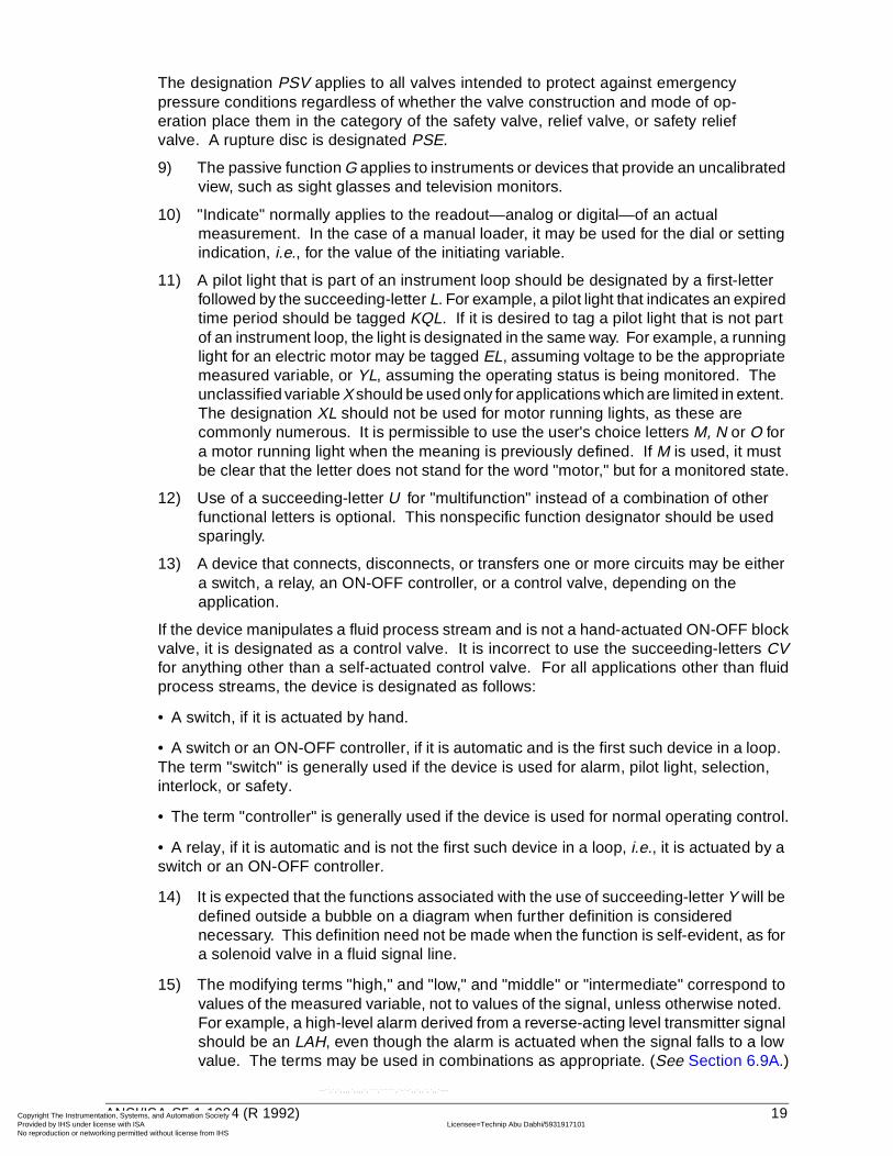
The designation PSV applies to all valves intended to protect against emergencypressure conditions regardless of whether the valve construction and mode of op-eration place them in the category of the safety valve, relief valve, or safety reliefvalve. A rupture disc is designated PSE.
9) The passive function G applies to instruments or devices that provide an uncalibrated view, such as sight glasses and television monitors.
10) "Indicate" normally applies to the readout—analog or digital—of an actual measurement. In the case of a manual loader, it may be used for the dial or setting indication, i.e., for the value of the initiating variable.
11) A pilot light that is part of an instrument loop should be designated by a first-letter followed by the succeeding-letter L. For example, a pilot light that indicates an expired time period should be tagged KQL. If it is desired to tag a pilot light that is not part of an instrument loop, the light is designated in the same way. For example, a running light for an electric motor may be tagged EL, assuming voltage to be the appropriate measured variable, or YL, assuming the operating status is being monitored. The unclassified variable X should be used only for applications which are limited in extent. The designation XL should not be used for motor running lights, as these are commonly numerous. It is permissible to use the user's choice letters M, N or O for a motor running light when the meaning is previously defined. If M is used, it must be clear that the letter does not stand for the word "motor," but for a monitored state.
12) Use of a succeeding-letter U for "multifunction" instead of a combination of other functional letters is optional. This nonspecific function designator should be used sparingly.
13) A device that connects, disconnects, or transfers one or more circuits may be either a switch, a relay, an ON-OFF controller, or a control valve, depending on the application.
If the device manipulates a fluid process stream and is not a hand-actuated ON-OFF blockvalve, it is designated as a control valve. It is incorrect to use the succeeding-letters CVfor anything other than a self-actuated control valve. For all applications other than fluidprocess streams, the device is designated as follows:
• A switch, if it is actuated by hand.
• A switch or an ON-OFF controller, if it is automatic and is the first such device in a loop. The term "switch" is generally used if the device is used for alarm, pilot light, selection, interlock, or safety.
• The term "controller" is generally used if the device is used for normal operating control.
• A relay, if it is automatic and is not the first such device in a loop, i.e., it is actuated by a switch or an ON-OFF controller.
14) It is expected that the functions associated with the use of succeeding-letter Y will be defined outside a bubble on a diagram when further definition is considered necessary. This definition need not be made when the function is self-evident, as for a solenoid valve in a fluid signal line.
15) The modifying terms "high," and "low," and "middle" or "intermediate" correspond to values of the measured variable, not to values of the signal, unless otherwise noted. For example, a high-level alarm derived from a reverse-acting level transmitter signal should be an LAH, even though the alarm is actuated when the signal falls to a low value. The terms may be used in combinations as appropriate. (See Section 6.9A.)
ANSI/ISA-S5.1-1984 (R 1992) 19
ntation, Systems, and Automation Society license with ISA Licensee=Technip Abu Dabhi/5931917101
Not for Resale, 02/12/2006 05:58:16 MSTorking permitted without license from IHS
--``,`,`,,,,`,,,,`,```,``````,`-`-`,,`,,`,`,,`---

Copyright The InstrumeProvided by IHS under No reproduction or netw
--``,`,`,,,,`,,,,`,```,``````,`-`-`,,`,,`,`,,`---
16) The terms "high" and "low," when applied to positions of valves and other open-close devices, are defined as follows: "high" denotes that the valve is in or approaching the fully open position, and "low" denotes that it is in or approaching the fully closed position.
17) The word "record" applies to any form of permanent storage of information that permits retrieval by any means.
18) For use of the term "transmitter" versus "converter," see the definitions in Section 3.
19) First-letter V, "vibration or mechanical analysis," is intended to perform the duties in machinery monitoring that the letter A performs in more general analyses. Except for vibration, it is expected that the variable of interest will be defined outside the tagging bubble.
20) First-letter Y is intended for use when control or monitoring responses are event-driven as opposed to time- or time schedule-driven. The letter Y, in this position, can also signify presence or state.
21) Modifying-letter K, in combination with a first-letter such as L, T, or W, signifies a time rate of change of the measured or initiating variable. The variable WKIC, for instance, may represent a rate-of-weight-loss controller.
22) Succeeding-letter K is a user's option for designating a control station, while the succeeding-letter C is used for describing automatic or manual controllers. (See Section 3, Definitions.)
20 ANSI/ISA-S5.1-1984 (R 1992)
ntation, Systems, and Automation Society license with ISA Licensee=Technip Abu Dabhi/5931917101
Not for Resale, 02/12/2006 05:58:16 MSTorking permitted without license from IHS

Copyright The InstrumeProvided by IHS under No reproduction or netw
--``,`,`,,,,`,,,,`,```,``````,`-`-`,,`,,`,`,,`---
Table 1 — Identification Letters
NOTE: Numbers in parentheses refer to specific explanatory notes in Section 5.1.
FIRST-LETTER (4) SUCCEEDING-LETTERS (3)
MEASURED OR INITIATING VARIABLE MODIFIER
READOUT OR PASSIVE
FUNCTION OUTPUT FUNCTION MODIFIER
A Analysis (5,19) Alarm
B Burner, Combustion User's Choice (1) User's Choice (1) User's Choice (1)
C User's Choice (1) Control (13)
D User's Choice (1) Differential (4)
E Voltage Sensor (Primary Element)
F Flow Rate Ratio (Fraction) (4)
G User's Choice (1) Glass, Viewing Device (9)
H Hand High (7, 15, 16)
I Current (Electrical) Indicate (10)
J Power Scan (7)
K Time, Time Schedule Time Rate of Change (4, 21)
Control Station (22)
L Level Light (11) Low (7, 15, 16)
M User's Choice (1) Momentary (4) Middle, Intermediate (7,15)
N User's Choice (1) User's Choice (1) User's Choice (1) User's Choice (1)
O User's Choice (1) Orifice, Restriction
P Pressure, Vacuum Point (Test) Connection
Q Quantity Integrate, Totalize (4)
R Radiation Record (17)
S Speed, Frequency Safety (8) Switch (13)
T Temperature Transmit (18)
U Multivariable (6) Multifunction (12) Multifunction (12) Multifunction (12)
V Vibration, Mechanical Analysis (19)
Valve, Damper, Louver (13)
W Weight, Force Well
X Unclassified (2) X Axis Unclassified (2) Unclassified (2) Unclassified (2)
Y Event, State or Presence (20)
Y Axis Relay, Compute, Convert (13, 14, 18)
Z Position, Dimension Z Axis Driver, Actuator, Unclassified Final Control Element
ANSI/ISA-S5.1-1984 (R 1992) 21
ntation, Systems, and Automation Society license with ISA Licensee=Technip Abu Dabhi/5931917101
Not for Resale, 02/12/2006 05:58:16 MSTorking permitted without license from IHS

Copyright The InstrumeProvided by IHS under No reproduction or netw
--``,`,`,,,,`,,,,`,```,``````,`-`-`,,`,,`,`,,`---
Tabl
e 2
— T
ypic
al L
ette
r C
ombi
natio
ns
Not
e: T
his
tabl
e is
not
all-
incl
usiv
e.
Oth
er P
ossi
ble
Com
bina
tions
:*A
, ala
rm, t
he a
nnun
ciat
ing
devi
ce, m
ay b
e us
ed in
the
sam
eF
O(R
estr
ictio
n O
rific
e)P
FR
(Rat
io)
fash
ion
as S
, sw
itch,
the
actu
atin
g de
vice
.F
RK
, HIK
(Con
trol
Sta
tions
)K
QI
(Run
ning
Tim
e In
dica
tor)
FX
(Acc
esso
ries)
I(I
ndic
atin
g C
ount
er)
**T
he le
tters
H a
nd L
may
be
omitt
ed in
the
unde
fined
cas
e.T
JR(S
cann
ing
Rec
orde
r)W
KIC
(Rat
e-of
-Wei
ght-
Loss
Con
trol
ler)
LLH
(Pilo
t Lig
ht)
HM
S(H
and
Mom
enta
ry S
witc
h)
Firs
t-Le
tters
Initi
atin
g or
M
easu
red
Vai
able
Con
trol
lers
Rea
dout
Dev
ices
Sw
itche
s an
d A
larm
Dev
ices
*Tr
ansm
itter
s
Sol
enoi
ds,
Rel
ays,
C
ompu
ting
Dev
ices
Prim
ary
Ele
men
tTe
st
Poi
nt
Wel
l or
P
robe
Vie
win
g D
evic
e,
Gla
ssS
afet
y D
evic
eF
inal
E
lem
ent
Rec
ordi
ngIn
dica
ting
Blin
d
Sel
f-A
ctua
ted
Con
trol
Val
ves
Rec
ordi
ng
Indi
catin
gH
igh*
*Lo
wC
omb
Rec
ordi
ngIn
dica
ting
Blin
d
AA
naly
sis
AR
CA
ICA
CA
RA
IA
SH
AS
LA
SH
LA
RT
AIT
ATAY
AE
AP
AW
AV
BB
urne
r/C
ombu
stio
nB
RC
BIC
BC
BR
BI
BS
HB
SL
BS
HL
BR
TB
ITB
TB
YB
EB
WB
GB
Z
CU
ser’s
Cho
ice
DU
ser’s
Cho
ice
EV
olta
geE
RC
EIC
EC
ER
EI
ES
HE
SL
ES
HL
ER
TE
ITE
TE
YE
EE
Z
FF
low
Rat
eF
RC
FIC
FC
FC
V,F
ICV
FR
FI
FS
HF
SL
FS
HL
FR
TF
ITF
TF
YF
EF
PF
GF
V
FQ
Flo
w Q
uant
ityF
QR
CF
QIC
FQ
RF
QI
FQ
SH
FQ
SL
FQ
ITF
QT
FQ
YF
QE
FQ
V
FF
Flo
w R
atio
FF
RC
FF
ICF
FC
FF
RF
FI
FF
SH
FF
SL
FE
FF
V
GU
ser’s
Cho
ice
HH
and
HIC
HC
HS
HV
IC
urre
ntIR
CIIC
IRII
ISH
ISL
ISH
LIR
TIIT
ITIY
IEIZ
JP
ower
JRC
JIC
JRJI
JSH
JSL
JSH
LJR
TJI
TJT
JYJE
JV
KT
ime
KR
CK
ICK
CK
CV
KR
KI
KS
HK
SL
KS
HL
KR
TK
ITK
TK
YK
EK
V
LLe
vel
LRC
LIC
LCLC
VLR
LILS
HLS
LLS
HL
LRT
LIT
LTLY
LELW
LGLV
MU
ser’s
Cho
ice
NU
ser’s
Cho
ice
OU
ser’s
Cho
ice
PP
ress
ure/
V
acuu
mP
RC
PIC
PC
PC
VP
RP
IP
SH
PS
LP
SH
LP
RT
PIT
PT
PY
PE
PP
PS
V,P
SE
PV
PD
Pre
ssur
e,
Diff
eren
tial
PD
RC
PD
ICP
DC
PD
CV
PD
RP
DI
PD
SH
PD
SL
PD
RT
PD
ITP
DT
PD
YP
EP
PP
DV
uant
ityQ
RC
QIC
QR
QI
QS
HQ
SL
QS
HL
QR
TQ
ITQ
TQ
YQ
EQ
Z
RR
adia
tion
RR
CR
ICR
CR
RR
IR
SH
RS
LR
SH
LR
RT
RIT
RT
RY
RE
RW
RZ
SS
peed
/Fre
quen
cyS
RC
SIC
SC
SC
VS
RS
IS
SH
SS
LS
SH
LS
RT
SIT
ST
SY
SE
SV
TTe
mpe
ratu
reT
RC
TIC
TC
TC
VT
RT
IT
SH
TS
LT
SH
LT
RT
TIT
TT
TY
TE
TP
TW
TS
ET
V
TD
Tem
pera
ture
,
Diff
eren
tial
TD
RC
TD
ICT
DC
TD
CV
TD
RT
DI
TD
SH
TD
SL
TD
RT
TD
ITT
DT
TD
YT
ET
PT
WT
DV
UM
ultiv
aria
ble
UR
UI
UY
UV
VV
ibra
tion/
Mac
hine
ry
Ana
lysi
sV
RV
IV
SH
VS
LV
SH
LV
RT
VIT
VT
VY
VE
VZ
WW
eigh
t/For
ceW
RC
WIC
WC
WC
VW
RW
IW
SH
WS
LW
SH
LW
RT
WIT
WT
WY
WE
WZ
WD
Wei
ght/F
orce
,
Diff
eren
tial
WD
RC
WD
ICW
DC
WD
CV
WD
RW
DI
WD
SH
WD
SL
WD
RT
WD
ITW
DT
WD
YW
EW
DZ
XU
ncla
ssifi
ed
YE
vent
/Sta
te/P
rese
nce
YIC
YC
YR
YI
YS
HY
SL
YT
YY
YE
YZ
ZP
ositi
on/D
imen
sion
ZR
CZ
ICZ
CZ
CV
ZR
ZI
ZS
HZ
SL
ZS
HL
ZR
TZ
ITZ
TZ
YZ
EZ
V
ZD
Gau
ging
/Dev
iatio
nZ
DR
CZ
DIC
ZD
CZ
DC
VZ
DR
ZD
IZ
DS
HZ
DS
LZ
DR
TZ
DIT
ZD
TZ
DY
ZD
EZ
DV
5.3
22 ANSI/ISA-S5.1-1984 (R 1992)
ntation, Systems, and Automation Society license with ISA Licensee=Technip Abu Dabhi/5931917101
Not for Resale, 02/12/2006 05:58:16 MSTorking permitted without license from IHS

Copyright The InstrumeProvided by IHS underNo reproduction or netw
--``,`,`,,,,`,,,,`
6
Tabl
e 3
— F
unct
ion
Blo
cks
- F
unct
ion
Des
igna
tions
TH
E F
UN
CT
ION
DE
SIG
NAT
ION
S A
SS
OC
IAT
ED
WIT
H C
ON
TR
OLL
ER
S, C
OM
PU
TIN
G D
EV
ICE
S, C
ON
VE
RT
ER
S A
ND
RE
LAY
S M
AY B
E U
SE
D IN
DIV
IDU
ALL
Y O
R IN
CO
MB
INAT
ION
(A
LSO
, SE
E T
AB
LE 1
, NO
TE
14.
). T
HE
US
E O
F
A B
OX
AV
OID
S C
ON
FU
SIO
N B
Y S
ET
TIN
G O
FF
TH
E S
YM
BO
L F
RO
M O
TH
ER
MA
RK
ING
S O
N A
DIA
GR
AM
AN
D P
ER
MIT
S T
HE
FU
NC
TIO
N T
O B
E U
SE
D A
S A
STA
ND
-ALO
NE
BLO
CK
ON
CO
NC
EP
TU
AL
DE
SIG
NS
.
5.4
ANSI/ISA-S5.1-1984 (R 1992) 23
ntation, Systems, and Automation Society license with ISA Licensee=Technip Abu Dabhi/5931917101
Not for Resale, 02/12/2006 05:58:16 MSTorking permitted without license from IHS
,```,``````,`-`-`,,`,,`,`,,`---

Copyright The InstrumeProvided by IHS under No reproduction or netw
5.4
Tabl
e 3
— C
ontin
ued
24 ANSI/ISA-S5.1-1984 (R 1992)
ntation, Systems, and Automation Society license with ISA Licensee=Technip Abu Dabhi/5931917101
Not for Resale, 02/12/2006 05:58:16 MSTorking permitted without license from IHS
--``,`,`,,,,`,,,,`,```,``````,`-`-`,,`,,`,`,,`---

Copyright The InstrumeProvided by IHS underNo reproduction or netw
--``,`,`,,,,`,,,,`,```,``````,`-`-`,,`,,`,`,,`---
5.4
Tabl
e 3
— C
ontin
ued
ANSI/ISA-S5.1-1984 (R 1992) 25
ntation, Systems, and Automation Society license with ISA Licensee=Technip Abu Dabhi/5931917101
Not for Resale, 02/12/2006 05:58:16 MSTorking permitted without license from IHS

Copyright The InstrumeProvided by IHS under No reproduction or netw
--``,`,`,,,,`,,,,`,```,``````,`-`-`,,`,,`,`,,`---
5.4
Tabl
e 3
— C
ontin
ued
26 ANSI/ISA-S5.1-1984 (R 1992)
ntation, Systems, and Automation Society license with ISA Licensee=Technip Abu Dabhi/5931917101
Not for Resale, 02/12/2006 05:58:16 MSTorking permitted without license from IHS

Copyright The InstrumeProvided by IHS under No reproduction or netw
--``,`,`,,,,`,,,,`,```,``````,`-`-`,,`,,`,`,,`---
6 Drawings
6.1 Cautionary notes
1) If a given drawing, or set of drawings, uses graphic symbols that are similar or identical in shape or configuration and that have different meanings because they are taken from different standards, then adequate steps must be taken to avoid misinterpretation of the symbols used. These steps may be to use caution notes, reference notes, comparison charts that illustrate and define the conflicting symbols, or other suitable means. This requirement is especially critical in cases where symbols taken from different disciplines are intermixed and their misinterpretation might cause danger to personnel or damage to equipment.
2) The titles Simplified Diagrams, Conceptual Diagrams and Detailed Diagrams of Section 6.12 were chosen to represent a cross section of symbol usage, not any particular generic document. (See 4.4.10 for a more complete discussion.)
3) The line symbols of Section 6.2 offer "user's choice" alternative electrical symbols and optional binary symbols. The subsequent examples use one consistent set of these alternatives and apply the binary options. This was done for consistency of appearance of the standard.
It is recommended that the user choose either the dashed line electrical symbol orthe triple cross hatch symbol and apply it consistently. The optional binary (on-off)symbols are available for those applications where the user finds it necessary todistinguish between analog and binary signals. If, in the user's judgment, the ap-plication does not require such differentiation, the reverse slash may be omittedfrom on-off signal line symbols. Consistency is recommended on a given set ofdocuments.
ANSI/ISA-S5.1-1984 (R 1992) 27
ntation, Systems, and Automation Society license with ISA Licensee=Technip Abu Dabhi/5931917101
Not for Resale, 02/12/2006 05:58:16 MSTorking permitted without license from IHS

Copyright The InstrumeProvided by IHS under No reproduction or netw
--``
6.2 Instrument line symbols
ALL LINES TO BE FINE IN RELATION TO PROCESS PIPING LINES.
,`,`,,,,`,,,,`,```,``````,`-`-`,,`,,`,`,,`---
28 ANSI/ISA-S5.1-1984 (R 1992)
ntation, Systems, and Automation Society license with ISA Licensee=Technip Abu Dabhi/5931917101
Not for Resale, 02/12/2006 05:58:16 MSTorking permitted without license from IHS

Copyright The InstrumeProvided by IHS under No reproduction or netw
6.3 General instrument or function symbols
--``,`,`,,,,`,,,,`,```,``````,`-`-`,,`,,`,`,,`---
ANSI/ISA-S5.1-1984 (R 1992) 29
ntation, Systems, and Automation Society license with ISA Licensee=Technip Abu Dabhi/5931917101
Not for Resale, 02/12/2006 05:58:16 MSTorking permitted without license from IHS
Copyright The InstrumeProvided by IHS under No reproduction or netw
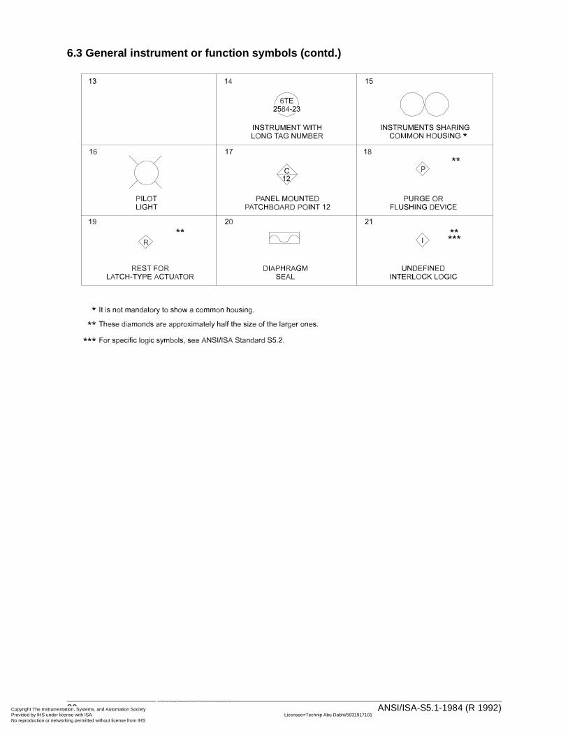
6.3 General instrument or function symbols (contd.)
30 ANSI/ISA-S5.1-1984 (R 1992)
ntation, Systems, and Automation Society license with ISA Licensee=Technip Abu Dabhi/5931917101
Not for Resale, 02/12/2006 05:58:16 MSTorking permitted without license from IHS
--``,`,`,,,,`,,,,`,```,``````,`-`-`,,`,,`,`,,`---

Copyright The InstrumeProvided by IHS under No reproduction or netw
6.4 Control valve body symbols, damper symbols
ANSI/ISA-S5.1-1984 (R 1992) 31
ntation, Systems, and Automation Society license with ISA Licensee=Technip Abu Dabhi/5931917101
Not for Resale, 02/12/2006 05:58:16 MSTorking permitted without license from IHS
--``,`,`,,,,`,,,,`,```,``````,`-`-`,,`,,`,`,,`---

Copyright The InstrumeProvided by IHS under No reproduction or netw
6.5 Actuator symbols
--``,`,`,,,,`,,,,`,```,``````,`-`-`,,`,,`,`,,`---
32 ANSI/ISA-S5.1-1984 (R 1992)
ntation, Systems, and Automation Society license with ISA Licensee=Technip Abu Dabhi/5931917101
Not for Resale, 02/12/2006 05:58:16 MSTorking permitted without license from IHS
Copyright The InstrumeProvided by IHS under No reproduction or netw
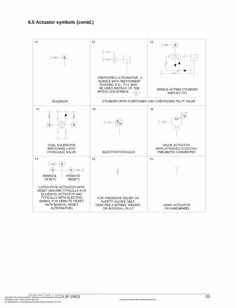
6.5 Actuator symbols (contd.)
ANSI/ISA-S5.1-1984 (R 1992) 33
ntation, Systems, and Automation Society license with ISA Licensee=Technip Abu Dabhi/5931917101
Not for Resale, 02/12/2006 05:58:16 MSTorking permitted without license from IHS
--``,`,`,,,,`,,,,`,```,``````,`-`-`,,`,,`,`,,`---

Copyright The InstrumeProvided by IHS under No reproduction or netw
6.6 Symbols for self-actuated regulators, valves, and other devices
34 ANSI/ISA-S5.1-1984 (R 1992)
ntation, Systems, and Automation Society license with ISA Licensee=Technip Abu Dabhi/5931917101
Not for Resale, 02/12/2006 05:58:16 MSTorking permitted without license from IHS
--``,`,`,,,,`,,,,`,```,``````,`-`-`,,`,,`,`,,`---

Copyright The InstrumeProvided by IHS under No reproduction or netw
--``,`,`,,,,`,,,,`,```,``````,`-`-`,,`,,`,`,,`---
6.6 Symbols for self-actuated regulators, valves, and other devices (contd.)
ANSI/ISA-S5.1-1984 (R 1992) 35
ntation, Systems, and Automation Society license with ISA Licensee=Technip Abu Dabhi/5931917101
Not for Resale, 02/12/2006 05:58:16 MSTorking permitted without license from IHS

Copyright The InstrumeProvided by IHS under No reproduction or netw
6.6 Symbols for self-actuated regulators, valves, and other devices (contd.)
36 ANSI/ISA-S5.1-1984 (R 1992)
ntation, Systems, and Automation Society license with ISA Licensee=Technip Abu Dabhi/5931917101
Not for Resale, 02/12/2006 05:58:16 MSTorking permitted without license from IHS
--``,`,`,,,,`,,,,`,```,``````,`-`-`,,`,,`,`,,`---

Copyright The InstrumeProvided by IHS under No reproduction or netw
--``,`,`,,,,`,,,,`,```,``````,`-`-`,,`,,`,`,,`---
6.7 Symbols for actuator action in event of actuator power failure (shown typically for diaphragm-actuated control valve).
ANSI/ISA-S5.1-1984 (R 1992) 37
ntation, Systems, and Automation Society license with ISA Licensee=Technip Abu Dabhi/5931917101
Not for Resale, 02/12/2006 05:58:16 MSTorking permitted without license from IHS
Copyright The InstrumeProvided by IHS under No reproduction or netw
--``,`,`,,,,`,,,,`,```,``````,`-`-`,,`,,`,`,,`---
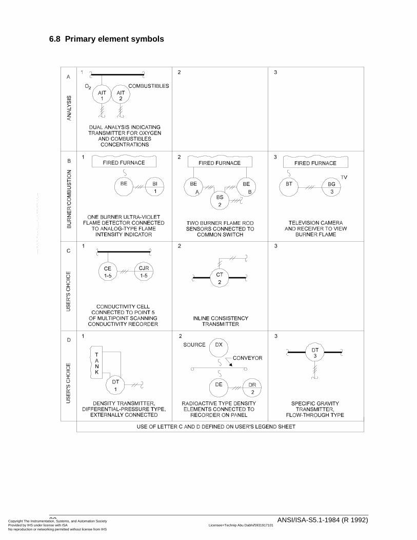
6.8 Primary element symbols
38 ANSI/ISA-S5.1-1984 (R 1992)
ntation, Systems, and Automation Society license with ISA Licensee=Technip Abu Dabhi/5931917101
Not for Resale, 02/12/2006 05:58:16 MSTorking permitted without license from IHS

Copyright The InstrumeProvided by IHS under No reproduction or netw
--``,`,`,,,,`,,,,`,```,``````,`-`-`,,`,,`,`,,`---
6.8 Primary element symbols (contd.)
ANSI/ISA-S5.1-1984 (R 1992) 39
ntation, Systems, and Automation Society license with ISA Licensee=Technip Abu Dabhi/5931917101
Not for Resale, 02/12/2006 05:58:16 MSTorking permitted without license from IHS

Copyright The InstrumeProvided by IHS under No reproduction or netw
--``,`,`,,,,`,,,,`,```,``````,`-`-`,,`,,`,`,,`---
6.8 Primary element symbols (contd.)
40 ANSI/ISA-S5.1-1984 (R 1992)
ntation, Systems, and Automation Society license with ISA Licensee=Technip Abu Dabhi/5931917101
Not for Resale, 02/12/2006 05:58:16 MSTorking permitted without license from IHS

Copyright The InstrumeProvided by IHS under No reproduction or netw
6.8 Primary element symbols (contd.)
ANSI/ISA-S5.1-1984 (R 1992) 41
ntation, Systems, and Automation Society license with ISA Licensee=Technip Abu Dabhi/5931917101
Not for Resale, 02/12/2006 05:58:16 MSTorking permitted without license from IHS
--``,`,`,,,,`,,,,`,```,``````,`-`-`,,`,,`,`,,`---

Copyright The InstrumeProvided by IHS under No reproduction or netw
--``,`,`,,,,`,,,,`,```,``````,`-`-`,,`,,`,`,,`---
6.8 Primary element symbols (contd.)
42 ANSI/ISA-S5.1-1984 (R 1992)
ntation, Systems, and Automation Society license with ISA Licensee=Technip Abu Dabhi/5931917101
Not for Resale, 02/12/2006 05:58:16 MSTorking permitted without license from IHS

Copyright The InstrumeProvided by IHS under No reproduction or netw
6.8 Primary element symbols (contd.)
ANSI/ISA-S5.1-1984 (R 1992) 43
ntation, Systems, and Automation Society license with ISA Licensee=Technip Abu Dabhi/5931917101
Not for Resale, 02/12/2006 05:58:16 MSTorking permitted without license from IHS
--``,`,`,,,,`,,,,`,```,``````,`-`-`,,`,,`,`,,`---

Copyright The InstrumeProvided by IHS under No reproduction or netw
6.8 Primary element symbols (contd.)
--``,`,`,,,,`,,,,`,```,``````,`-`-`,,`,,`,`,,`---
44 ANSI/ISA-S5.1-1984 (R 1992)
ntation, Systems, and Automation Society license with ISA Licensee=Technip Abu Dabhi/5931917101
Not for Resale, 02/12/2006 05:58:16 MSTorking permitted without license from IHS

Copyright The InstrumeProvided by IHS under No reproduction or netw
6.8 Primary element symbols (contd.)
ANSI/ISA-S5.1-1984 (R 1992) 45
ntation, Systems, and Automation Society license with ISA Licensee=Technip Abu Dabhi/5931917101
Not for Resale, 02/12/2006 05:58:16 MSTorking permitted without license from IHS
--``,`,`,,,,`,,,,`,```,``````,`-`-`,,`,,`,`,,`---

Copyright The InstrumeProvided by IHS under No reproduction or netw
6.8 Primary element symbols (contd.)
46 ANSI/ISA-S5.1-1984 (R 1992)
ntation, Systems, and Automation Society license with ISA Licensee=Technip Abu Dabhi/5931917101
Not for Resale, 02/12/2006 05:58:16 MSTorking permitted without license from IHS
--``,`,`,,,,`,,,,`,```,``````,`-`-`,,`,,`,`,,`---

Copyright The InstrumeProvided by IHS under No reproduction or netw
6.8 Primary element symbols (contd.)
ANSI/ISA-S5.1-1984 (R 1992) 47
ntation, Systems, and Automation Society license with ISA Licensee=Technip Abu Dabhi/5931917101
Not for Resale, 02/12/2006 05:58:16 MSTorking permitted without license from IHS
--``,`,`,,,,`,,,,`,```,``````,`-`-`,,`,,`,`,,`---

Copyright The InstrumeProvided by IHS under No reproduction or netw
6.9 Examples — functions
--``,`,`,,,,`,,,,`,```,``````,`-`-`,,`,,`,`,,`---
48 ANSI/ISA-S5.1-1984 (R 1992)
ntation, Systems, and Automation Society license with ISA Licensee=Technip Abu Dabhi/5931917101
Not for Resale, 02/12/2006 05:58:16 MSTorking permitted without license from IHS

Copyright The InstrumeProvided by IHS under No reproduction or netw
6.9 Examples — functions (contd.)
ANSI/ISA-S5.1-1984 (R 1992) 49
ntation, Systems, and Automation Society license with ISA Licensee=Technip Abu Dabhi/5931917101
Not for Resale, 02/12/2006 05:58:16 MSTorking permitted without license from IHS
--``,`,`,,,,`,,,,`,```,``````,`-`-`,,`,,`,`,,`---

Copyright The InstrumeProvided by IHS under No reproduction or netw
--``,`,`,,,,`,,,,`,```,``````,`-`-`,,`,,`,`,,`---
6.9 Examples — functions (contd.)
50 ANSI/ISA-S5.1-1984 (R 1992)
ntation, Systems, and Automation Society license with ISA Licensee=Technip Abu Dabhi/5931917101
Not for Resale, 02/12/2006 05:58:16 MSTorking permitted without license from IHS

Copyright The InstrumeProvided by IHS under No reproduction or netw
--``,`,`,,,,`,,,,`,```,``````,`-`-`,,`,,`,`,,`---
6.9 Examples — functions (contd.)
ANSI/ISA-S5.1-1984 (R 1992) 51
ntation, Systems, and Automation Society license with ISA Licensee=Technip Abu Dabhi/5931917101
Not for Resale, 02/12/2006 05:58:16 MSTorking permitted without license from IHS

Copyright The InstrumeProvided by IHS under No reproduction or netw
6.9 Examples — functions (contd.)
--``,`,`,,,,`,,,,`,```,``````,`-`-`,,`,,`,`,,`---
52 ANSI/ISA-S5.1-1984 (R 1992)
ntation, Systems, and Automation Society license with ISA Licensee=Technip Abu Dabhi/5931917101
Not for Resale, 02/12/2006 05:58:16 MSTorking permitted without license from IHS
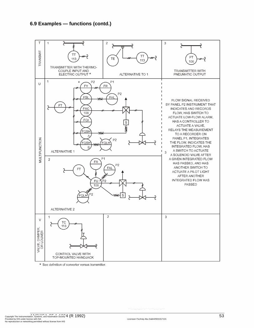
Copyright The InstrumeProvided by IHS under No reproduction or netw
6.9 Examples — functions (contd.)
--``,`,`,,,,`,,,,`,```,``````,`-`-`,,`,,`,`,,`---
ANSI/ISA-S5.1-1984 (R 1992) 53
ntation, Systems, and Automation Society license with ISA Licensee=Technip Abu Dabhi/5931917101
Not for Resale, 02/12/2006 05:58:16 MSTorking permitted without license from IHS

Copyright The InstrumeProvided by IHS under No reproduction or netw
6.9 Examples — functions (contd.)
--``,`,`,,,,`,,,,`,```,``````,`-`-`,,`,,`,`,,`---
54 ANSI/ISA-S5.1-1984 (R 1992)
ntation, Systems, and Automation Society license with ISA Licensee=Technip Abu Dabhi/5931917101
Not for Resale, 02/12/2006 05:58:16 MSTorking permitted without license from IHS

Copyright The InstrumeProvided by IHS under No reproduction or netw
--``
6.9 Examples — functions (contd.)
,`,`,,,,`,,,,`,```,``````,`-`-`,,`,,`,`,,`---
ANSI/ISA-S5.1-1984 (R 1992) 55
ntation, Systems, and Automation Society license with ISA Licensee=Technip Abu Dabhi/5931917101
Not for Resale, 02/12/2006 05:58:16 MSTorking permitted without license from IHS

Copyright The InstrumeProvided by IHS under No reproduction or netw
6.10 Examples — miscellaneous combinations
--``,`,`,,,,`,,,,`,```,``````,`-`-`,,`,,`,`,,`---
56 ANSI/ISA-S5.1-1984 (R 1992)
ntation, Systems, and Automation Society license with ISA Licensee=Technip Abu Dabhi/5931917101
Not for Resale, 02/12/2006 05:58:16 MSTorking permitted without license from IHS

Copyright The InstrumeProvided by IHS under No reproduction or netw
--``,`,`,,,,`,,,,`,```,``````,`-`-`,,`,,`,`,,`---
6.10 Examples — miscellaneous combinations (contd.)
ANSI/ISA-S5.1-1984 (R 1992) 57
ntation, Systems, and Automation Society license with ISA Licensee=Technip Abu Dabhi/5931917101
Not for Resale, 02/12/2006 05:58:16 MSTorking permitted without license from IHS

Copyright The InstrumeProvided by IHS under No reproduction or netw
6.10 Examples — miscellaneous combinations (contd.)
58 ANSI/ISA-S5.1-1984 (R 1992)
ntation, Systems, and Automation Society license with ISA Licensee=Technip Abu Dabhi/5931917101
Not for Resale, 02/12/2006 05:58:16 MSTorking permitted without license from IHS
--``,`,`,,,,`,,,,`,```,``````,`-`-`,,`,,`,`,,`---

Copyright The InstrumeProvided by IHS under No reproduction or netw
6.10 Examples — miscellaneous combinations (contd.)
ANSI/ISA-S5.1-1984 (R 1992) 59
ntation, Systems, and Automation Society license with ISA Licensee=Technip Abu Dabhi/5931917101
Not for Resale, 02/12/2006 05:58:16 MSTorking permitted without license from IHS
--``,`,`,,,,`,,,,`,```,``````,`-`-`,,`,,`,`,,`---

Copyright The InstrumeProvided by IHS under No reproduction or netw
--``,`,`,,,,`,,,,`,```,``````,`-`-`,,`,,`,`,,`---
6.10 Examples — miscellaneous combinations (contd.)
60 ANSI/ISA-S5.1-1984 (R 1992)
ntation, Systems, and Automation Society license with ISA Licensee=Technip Abu Dabhi/5931917101
Not for Resale, 02/12/2006 05:58:16 MSTorking permitted without license from IHS

Copyright The InstrumeProvided by IHS under No reproduction or netw
--``,`,`,,,,`,,,,`,```,``````,`-`-`,,`,,`,`,,`---
6.11 Example — complex combinations
ANSI/ISA-S5.1-1984 (R 1992) 61
ntation, Systems, and Automation Society license with ISA Licensee=Technip Abu Dabhi/5931917101
Not for Resale, 02/12/2006 05:58:16 MSTorking permitted without license from IHS

Copyright The InstrumeProvided by IHS under No reproduction or netw
6.12 Example — degree of detail*
--``,`,`,,,,`,,,,`,```,``````,`-`-`,,`,,`,`,,`---
62 ANSI/ISA-S5.1-1984 (R 1992)
ntation, Systems, and Automation Society license with ISA Licensee=Technip Abu Dabhi/5931917101
Not for Resale, 02/12/2006 05:58:16 MSTorking permitted without license from IHS

Copyright The InstrumeProvided by IHS under No reproduction or netw
6.12 Example — degree of detail (contd.)*
ANSI/ISA-S5.1-1984 (R 1992) 63
ntation, Systems, and Automation Society license with ISA Licensee=Technip Abu Dabhi/5931917101
Not for Resale, 02/12/2006 05:58:16 MSTorking permitted without license from IHS
--``,`,`,,,,`,,,,`,```,``````,`-`-`,,`,,`,`,,`---

Copyright The InstrumeProvided by IHS under No reproduction or netw
--``,`,`,,,,`,,,,`,```,``````,`-`-`,,`,,`,`,,`---
6.12 Example — degree of detail (contd.)*
64 ANSI/ISA-S5.1-1984 (R 1992)
ntation, Systems, and Automation Society license with ISA Licensee=Technip Abu Dabhi/5931917101
Not for Resale, 02/12/2006 05:58:16 MSTorking permitted without license from IHS

Copyright The IProvided by IHSNo reproduction
Index
Term Para. No. Term Para. No.
nstrume under or netw
- A -Accessible
definition ..............................3graphic symbols ...................6.3
Actuatoractuator action...................... 6.7graphic symbols ...................6.5identification ......................... 5.1
Air Supplyidentification ......................... 6.2
Alarmdefinition............................... 3examples ..............................6.9identification ......................... 5.1
Analysisexamples ..............................6.8identification ......................... 5.1
Assignabledefinition............................... 3
Auto-Manual Station(Control Station)definition............................... 3identification ......................... 5.1
Auxiliary Locationgraphic symbol ..................... 6.3
Averaginggraphic symbol ..................... 5.4
- B -Balloon, Bubble
definition............................... 3graphic symbol ..................... 6.3
Behind-the-Paneldefinition............................... 3graphic symbol ..................... 6.3
Biasgraphic symbol ..................... 5.4
Binarydefinition...............................3graphic symbol .....................6.2
Board (Panel)definition...............................3identification .........................6.3
Burner, Combustionexample................................6.8identification .........................5.1
- C -Complex Combinations
example................................6.11Computer Function
graphic symbol .....................6.3Computing Device
definition...............................3example................................6.9function.................................5.4identification .........................5.1
Conceptual Diagramsexample................................6.12
Conductivity (see Analysis)example................................6.8
Configurabledefinition...............................3
Controllerdefinition...............................3
Controlexample................................6.9identification .........................5.1
Control Station(Auto-Manual Station)
definition...............................3example................................6.9identification .........................5.1
Control Valvedefinition...............................3
--``,`,`,,,,`,,,,`,```,``````,`-`-`,,`,,`,`,,`---
ANSI/ISA-S5.1-1984 (R 1992) 65
ntation, Systems, and Automation Society license with ISA Licensee=Technip Abu Dabhi/5931917101
Not for Resale, 02/12/2006 05:58:16 MSTorking permitted without license from IHS

Copyright The InstrumeProvided by IHS under No reproduction or netw
--``,`,`,,,,`,,,,`,```,``````,`-`-`,,`,,`,`,,`---
Term Para. No.graphic symbols ...................6.4identification ......................... 5.1self-actuated......................... 6.6
Converterdefinition............................... 3graphic symbols ...................5.4
Current (Electrical)graphic symbols ...................6.8identification ......................... 5.1
- D -Damper
graphic symbol ..................... 6.4Data Link
graphic symbol ..................... 6.2Density
example................................ 6.8Derivative
graphic symbol ..................... 5.4Detailed Diagrams
example................................ 6.12Diaphragm Seal
graphic symbol ..................... 6.3Difference
graphic symbol ..................... 5.4Differential
examples ..............................6.6, 6.9identification ......................... 5.1
Digitaldefinition............................... 3graphic symbol ..................... 6.5
Dimensionidentification ......................... 5.1
Discrete Instrumentsgraphic symbol ..................... 6.3
Distributed Control Systemdefinition............................... 3
Dividinggraphic symbol ..................... 5.4
Driverexample................................ 6.9identification ......................... 5.1
- E -Electric Binary Signal
Term Para. No.graphic symbol .....................6.2
Electric Signalgraphic symbols ...................6.2
Electric Supplyidentification .........................6.2
Electrohydraulicgraphic symbol .....................6.5
Electromagnetic Signalgraphic symbols ...................6.2
Eventidentification .........................5.1
Exponentialgraphic symbol .....................5.4
- F -Field Mounted (Local)
graphic symbol .....................6.3Final Control Element
definition...............................3identification .........................5.1
Flow Rategraphic symbols ...................6.8identification .........................5.1
Forceexample................................6.8identification .........................5.1
Frequencyidentification .........................5.1
Functiondefinition...............................3examples..............................6.9graphic symbols ...................6.3identification .........................5.1, 5.4
Function Blocksidentification .........................5.4
Fusible Plugexample................................6.6
- G -Gas Supply
identification .........................6.2Glass (Viewing Device)
example................................6.9graphic symbols ...................6.8identification .........................5.1
66 ANSI/ISA-S5.1-1984 (R 1992)
ntation, Systems, and Automation Society license with ISA Licensee=Technip Abu Dabhi/5931917101
Not for Resale, 02/12/2006 05:58:16 MSTorking permitted without license from IHS

Copyright The InstrumeProvided by IHS under No reproduction or netw
Term Para. No.- H -
Hand (Manually Actuated)example................................ 6.9graphic symbols ...................6.6identification ......................... 5.1
Hand Wheelgraphic symbol ..................... 6.5
Highidentification ......................... 5.1
High Limitinggraphic symbol ..................... 5.4
High Selectinggraphic symbol ..................... 5.4
Hydraulic Signalgraphic symbol ..................... 6.2
Hydraulic Supplyidentification ......................... 6.2
- I -Identification
combinations example ......... 5.3definition............................... 3letters ................................... 5.1
Indicateexample................................ 6.9identification ......................... 5.1
Instrumentdefinition............................... 3
Instrument Airidentification ......................... 6.2
Instrumentationdefinition............................... 3
Instrument Line Symbols ........... 6.2Integral
graphic symbol ..................... 5.4Integrate
example................................ 6.9identification ......................... 5.1
Interlockexample................................ 6.9graphic symbol ..................... 6.3
- L -Letter Combinations...................5.3
Term Para. No.Level
graphic symbol .....................6.8, 6.6identification .........................5.1
Lightexample................................6.9graphic symbol .....................6.3identification .........................5.1
Local (Field)definition...............................3graphic symbol .....................6.3
Local Paneldefinition...............................3identification .........................6.3
Loopdefinition...............................3identification .........................4.3
Louversee Damper
Lowexample................................6.9identification .........................5.1
Low Limitinggraphic symbol .....................5.4
Low Selectinggraphic symbol .....................5.4
- M -Manual Loading Station
definition...............................3Measurement
definition...............................3Mechanical Analysis
identification .........................5.1Mechanical Link
graphic symbol .....................6.2Middle (Intermediate)
identification .........................5.1Moisture
see AnalysisMomentary
identification .........................5.1Monitor
definition...............................3
ANSI/ISA-S5.1-1984 (R 1992) 67
ntation, Systems, and Automation Society license with ISA Licensee=Technip Abu Dabhi/5931917101
Not for Resale, 02/12/2006 05:58:16 MSTorking permitted without license from IHS
--``,`,`,,,,`,,,,`,```,``````,`-`-`,,`,,`,`,,`---

Copyright The InstrumeProvided by IHS under No reproduction or netw
Term Para. No.Multifunction
example................................ 6.9identification ......................... 5.1
Multiplyinggraphic symbol ..................... 5.4
Multivariablegraphic symbols ...................6.8identification ......................... 5.1
- N -Nitrogen Supply
identification ......................... 6.2Non-Linear
graphic symbol ..................... 5.4- O -
Orificeidentification ......................... 5.1
Orifice Plate Tapsgraphic symbols ...................6.8
- P -Panel (Board)(Primary Location)
definition............................... 3graphic symbols ...................6.3
Panel-Mounted(Board-Mounted)
definition............................... 3graphic symbols ...................6.3
Pilot Lightdefinition............................... 3graphic symbol ..................... 6.3identification ......................... 5.1
Plant Airidentification ......................... 6.2
Pneumatic Binary Signalgraphic symbol ..................... 6.2
Pneumatic Signalgraphic symbol ..................... 6.2
Point (Test)example................................ 6.9identification ......................... 5.1
Positiongraphic symbol ..................... 6.8identification ......................... 5.1
Term Para. No.Power
graphic symbol .....................6.8identification ........................5.1
Presenceidentification .........................5.1
Pressure Relief Valvessee Safety Relief Valves
Pressure (or Vacuum)graphic symbols ...................6.6, 6.8identification .........................5.1
Printexample................................6.9
Primary Element (Sensor)definition............................... see Sensorgraphic symbols ...................6.8
Processdefinition...............................3
Process Variabledefinition...............................3
Programdefinition...............................3
Programmable LogicController
definition...............................3example................................6.10, 6.11graphic symbol .....................6.3
Proportionalgraphic symbol .....................5.4
Purgeexample................................6.10graphic symbol .....................6.3
- Q -Quantity
examples..............................6.9graphic symbols ...................6.8identification .........................5.1
- R -Radiation
graphic symbol .....................6.8Ratio
example................................6.9identification .........................5.1
--``,`,`,,,,`,,,,`,```,``````,`-`-`,,`,,`,`,,`---
68 ANSI/ISA-S5.1-1984 (R 1992)
ntation, Systems, and Automation Society license with ISA Licensee=Technip Abu Dabhi/5931917101
Not for Resale, 02/12/2006 05:58:16 MSTorking permitted without license from IHS

Copyright The InstrumeProvided by IHS under No reproduction or netw
--``,`,`,,,,`,,,,`,```,``````,`-`-`,,`,,`,`,,`---
Term Para. No.Record
example................................ 6.9identification ......................... 5.1
Relaydefinition............................... 3examples ..............................6.9graphic symbols ...................5.4
Relief Valvesee Safety Relief Valve
Resetgraphic symbol ..................... 6.3
Restriction Orificegraphic symbol ..................... 6.6
Reverse Proportionalgraphic symbol ..................... 5.4
Root Extractiongraphic symbol ..................... 5.4
Rupture Discgraphic symbols ...................6.6
- S -Safety
identification ......................... 5.1Safety Purging
example................................ 6.10Safety Relief Valves
graphic symbols ...................6.6Scan
definition............................... 3example................................ 6.9identification ......................... 5.1
Self-Actuated Devicesgraphic symbols ...................6.6identification ......................... 4.2.5
Sensor (Primary Element)definition............................... 3graphic symbols ...................6.8
Set Pointdefinition............................... 3
Shared Controllerdefinition............................... 3graphic symbols ...................6.3
Shared Displaydefinition ..............................3
Term Para. No.graphic symbols ...................6.3
Sight Glassgraphic symbol .....................6.6
Signal Monitorgraphic symbol .....................5.4
Simplified Diagramexample................................6.12
Solenoidgraphic symbol .....................6.5
Specific Gravityexample................................6.8
Speed identification .........................5.1Steam Supply
identification .........................6.2Straightening Vane
graphic symbol .....................6.6Summing graphic symbol .....................5.4Switch
definition...............................3example................................6.9identification .........................5.1
- T -Temperature
graphic symbols ...................6.8identification .........................5.1
Test Pointdefinition...............................3example................................6.9identification .........................5.1
Time Functiongraphic symbol ..................... 5.4
Time Rate of Changeidentification .........................5.1
Time, Time Schedulegraphic symbols ...................6.8identification .........................5.1
Totalizesee Integrate
Transducerdefinition...............................3
Transmitter
ANSI/ISA-S5.1-1984 (R 1992) 69
ntation, Systems, and Automation Society license with ISA Licensee=Technip Abu Dabhi/5931917101
Not for Resale, 02/12/2006 05:58:16 MSTorking permitted without license from IHS
Copyright The InstrumeProvided by IHS under No reproduction or netw
Term Para. No.definition............................... 3example................................ 6.9identification ......................... 5.1
Trapsexample................................ 6.6
Typical LetterCombinations ....................... 5.3
- U -Unclassified
identification ......................... 5.1Undefined Signal
graphic symbols ...................6.2User's Choice
examples ..............................6.8identification ......................... 5.1
- V -Vacuum
see PressureValve
see Control ValveVelocity Limiter
graphic symbol ..................... 5.4Vibration
identification ......................... 5.1Voltage
graphic symbols ...................6.8identification ......................... 5.1
- W -Water Supply
identification ......................... 6.2Weight
identification ......................... 5.1Well
graphic symbols ...................6.8identification ......................... 5.1
- X -X-Axis
identification ......................... 5.1- Y -
Y-Axisidentification ......................... 5.1
- Z-Z-Axis
identification .........................5.1
--``,`,`,,,,`,,,,`,```,``````,`-`-`,,`,,`,`,,`---
70 ANSI/ISA-S5.1-1984 (R 1992)
ntation, Systems, and Automation Society license with ISA Licensee=Technip Abu Dabhi/5931917101
Not for Resale, 02/12/2006 05:58:16 MSTorking permitted without license from IHS

Copyright The InstrumeProvided by IHS under No reproduction or netw
ntation, Systems, and Automation Society license with ISA Licensee=Technip Abu Dabhi/5931917101
Not for Resale, 02/12/2006 05:58:16 MSTorking permitted without license from IHS
--``,`,`,,,,`,,,,`,```,``````,`-`-`,,`,,`,`,,`---

Developing and promulgating technically sound consensus standards, recommended practices, and technical reports is one of ISA's primary goals. To achieve this goal the Standards and Practices Department relies on the technical expertise and efforts of volunteer commi ttee members, chairmen, and reviewers.
ISA is an American National Standards Institute (ANSI) accredited organization. ISA administers United States Technical Advisory Groups (USTAGs) and provides secretariat support for International Electrotechnical Commission (IEC) and International Organization for Standardization (ISO) committees that develop process measurement and control standards. To obtain additional information on the Society's standards program, please write:
ISAAttn: Standards Department67 Alexander DriveP.O. Box 12277Research Triangle Park, NC 27709
ISBN: 0-87664-844-8
Copyright The Instrumentation, Systems, and Automation Society Provided by IHS under license with ISA Licensee=Technip Abu Dabhi/5931917101
Not for Resale, 02/12/2006 05:58:16 MSTNo reproduction or networking permitted without license from IHS
--``,`,`,,,,`,,,,`,```,``````,`-`-`,,`,,`,`,,`---