Embed Size (px)
Citation preview
Instrumentation for battery research Product OverviewSpring 2020

EL-Cell GmbH was founded 10 years ago in Hamburg, Germany.
Since then, we have been developing laboratory equipment for
research of energy storage systems, with particular focus on
lithium-ion technology. We are distinguished by our expertise in
electrochemistry and mechanical engineering as well as our eager
ambition to develop innovative products.
We strongly believe that reliable and simple 3-electrode
measurements are the most efficient way to develop new battery
materials. This approach proves to be particularly useful in our
PAT (PArallel Testing) series, a modular test cell system with the
highest standards of efficiency and ease of use. In addition, we
offer a variety of in-situ test cells as well as tools for manufacturing
battery components in the laboratory.
Our complete range of services is rounded out with our own
potentiostats, which are precisely tailored to the special
requirements of battery research.
This allows us to provide you with the complete set-up from a
single source to carry out electrochemical experiments.
We also offer hands-on seminars so you can familiarise yourself
with our instruments and benefit directly from our expertise. The
training takes place in our own fully equipped battery lab, where
we will also gladly perform a variety of measurement services for
you. We are also readily available to find specific solutions for your
individual tasks.
This brochure provides an overview of our current products and
services.
3
Content
The PAT Series .................................................................. 4
PAT-Core .......................................................................... 6
PAT-Core Configurations ................................................... 7
Advanced Use Cases with the PAT-Core............................. 9
PAT-Core Components ...................................................... 10
PAT Test Cells
PAT-Cell ............................................................................ 11
PAT-Cell-Gas ..................................................................... 12
PAT-Cell-Press ................................................................... 14
PAT-Cell-HT ...................................................................... 15
Optional Accessories for PAT Test Cells ............................. 16
PAT Docking Stations
PAT-Clamp-1 ..................................................................... 17
PAT-Stand-1 ..................................................................... 18
PAT-Stand-4 ..................................................................... 19
PAT-Stand-16 ................................................................... 20
PAT-Heater-4 ................................................................... 21
PAT-Chamber-16 ............................................................... 22
We Advance Battery Research.
PAT Battery Tester ............................................................. 23
PAT-Tester-i-16 .................................................................. 24
PAT-Tester-x-8.................................................................... 26
PAT Battery Tester Specifications ....................................... 27
EL-Software ...................................................................... 28
In-situ Test Cells
Electrochemical Dilatometer ............................................. 30
ECC-Opto-Std ................................................................... 32
ECC-Opto-Std-Aqu ............................................................ 34
ECC-Opto-Gas .................................................................. 36
Accessories & Tools
PAT-Connect-16 ................................................................ 37
EL-Cut .............................................................................. 38
ECC-LiPunch ..................................................................... 38
Services
Lithium battery application Lab ........................................ 39
Hands-on Seminars .......................................................... 40
Customizations ................................................................. 41
Tables .............................................................................. 42
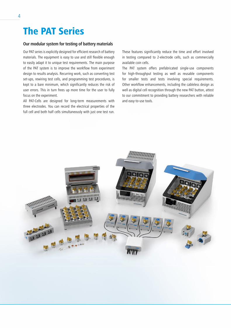
These features significantly reduce the time and effort involved
in testing compared to 2-electrode cells, such as commercially
available coin cells.
The PAT system offers prefabricated single-use components
for high-throughput testing as well as reusable components
for smaller tests and tests involving special requirements.
Other workflow enhancements, including the cableless design as
well as digital cell recognition through the new PAT button, attest
to our commitment to providing battery researchers with reliable
and easy-to-use tools.
4
The PAT SeriesOur modular system for testing of battery materials
Our PAT series is explicitly designed for efficient research of battery
materials. The equipment is easy to use and still flexible enough
to easily adapt it to unique test requirements. The main purpose
of the PAT system is to improve the workflow from experiment
design to results analysis. Recurring work, such as converting test
set-ups, rewiring test cells, and programming test procedures, is
kept to a bare minimum, which significantly reduces the risk of
user errors. This in turn frees up more time for the user to fully
focus on the experiment.
All PAT-Cells are designed for long-term measurements with
three electrodes. You can record the electrical properties of the
full cell and both half cells simultaneously with just one test run.
5
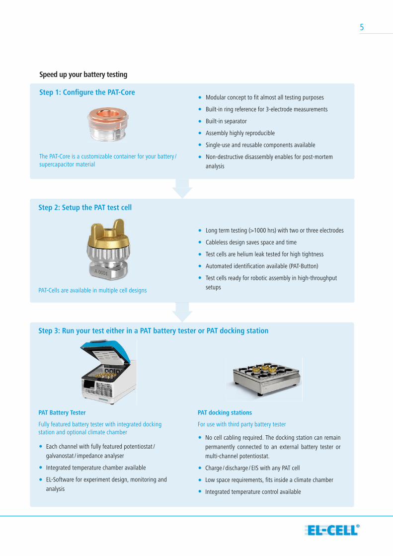
Speed up your battery testing
Step 1: Confi gure the PAT-Core
The PAT-Core is a customizable container for your battery / supercapacitor material
Step 2: Setup the PAT test cell
PAT Battery Tester
Fully featured battery tester with integrated docking station and optional climate chamber
PAT-Cells are available in multiple cell designs
Long term testing (>1000 hrs) with two or three electrodes
Cableless design saves space and time
Test cells are helium leak tested for high tightness
Automated identification available (PAT-Button)
Test cells ready for robotic assembly in high-throughput
setups
Modular concept to fit almost all testing purposes
Built-in ring reference for 3-electrode measurements
Built-in separator
Assembly highly reproducible
Single-use and reusable components available
Non-destructive disassembly enables for post-mortem
analysis
Step 3: Run your test either in a PAT battery tester or PAT docking station
PAT docking stations
For use with third party battery tester
No cell cabling required. The docking station can remain
permanently connected to an external battery tester or
multi-channel potentiostat.
Charge / discharge / EIS with any PAT cell
Low space requirements, fits inside a climate chamber
Integrated temperature control available
Each channel with fully featured potentiostat /
galvanostat / impedance analyser
Integrated temperature chamber available
EL-Software for experiment design, monitoring and
analysis
PAT-CoreEnabling battery studies of unmatched quality
The PAT-Core is the world-wide patented, essential part of the PAT-
Cell. It holds the electrodes undergoing testing in place and allows
for precise alignment of the cell stack. The well-defined geometry
of the PAT-Core enables high-quality two- and three-electrode tests
of Li-ion and other battery materials as well as supercapacitors.
The easy assembly of the PAT-Core minimizes the human factor in
experiment preparation and even qualifies for robotic assembly.
The standard PAT-Core comprises three components. The first
part is a highly customizable insulation sleeve with a built-
in separator and ring-shaped reference electrode. Different
reference materials like sodium or magnesium and various
separator materials such as glass fibre or microporous
polyolefin are available. The single-use concept lowers lead
times in the lab and minimizes the risk of cross-contamination.
Highlights of the PAT-Core High-precision concentric geometry of cell stack without
manual alignment
Modular concept adaptable for various configurations
Long-term ( >1000 hrs ) half-cell measurements with three
electrodes
The insulation sleeve is preassembled under a protective argon
atmosphere at the EL-CELL® factory to ensure consistent quality for
reproducible battery tests. PEEK is now made available as alternative
material for the insulation sleeve; this way we are also able to offer
the insulation sleeve as a reusable version for self-assembly.
The upper and lower plungers complete the PAT-Core and serve
as current collectors. Battery researchers can choose from a broad
range of different materials: battery-grade aluminum and copper,
reusable stainless steel or precious metals, such as gold or platinum
for special demands.
This way the PAT-Core is ready for both aprotic and aqueous
electrolytes as well as special purposes such as high temperature
environments.
Easy, reproducible and automatable assembly - with and
without reference electrode
All battery-grade materials available: Al, Cu, polypropylene
Optionally reusable insulation sleeve and current collectors
6
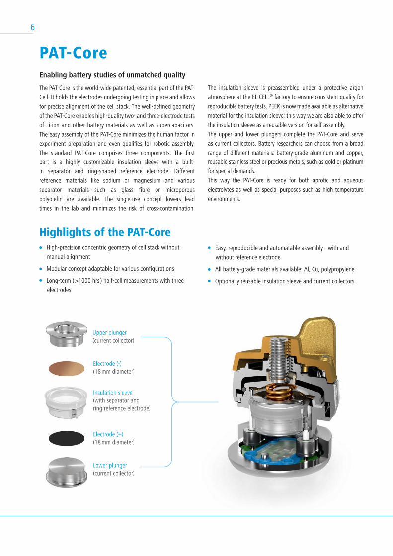
Upper plunger (current collector)
Electrode (-)(18 mm diameter)
Electrode (+)(18 mm diameter)
Lower plunger(current collector)
Insulation sleeve(with separator andring reference electrode)
7
PAT-Core Configurations
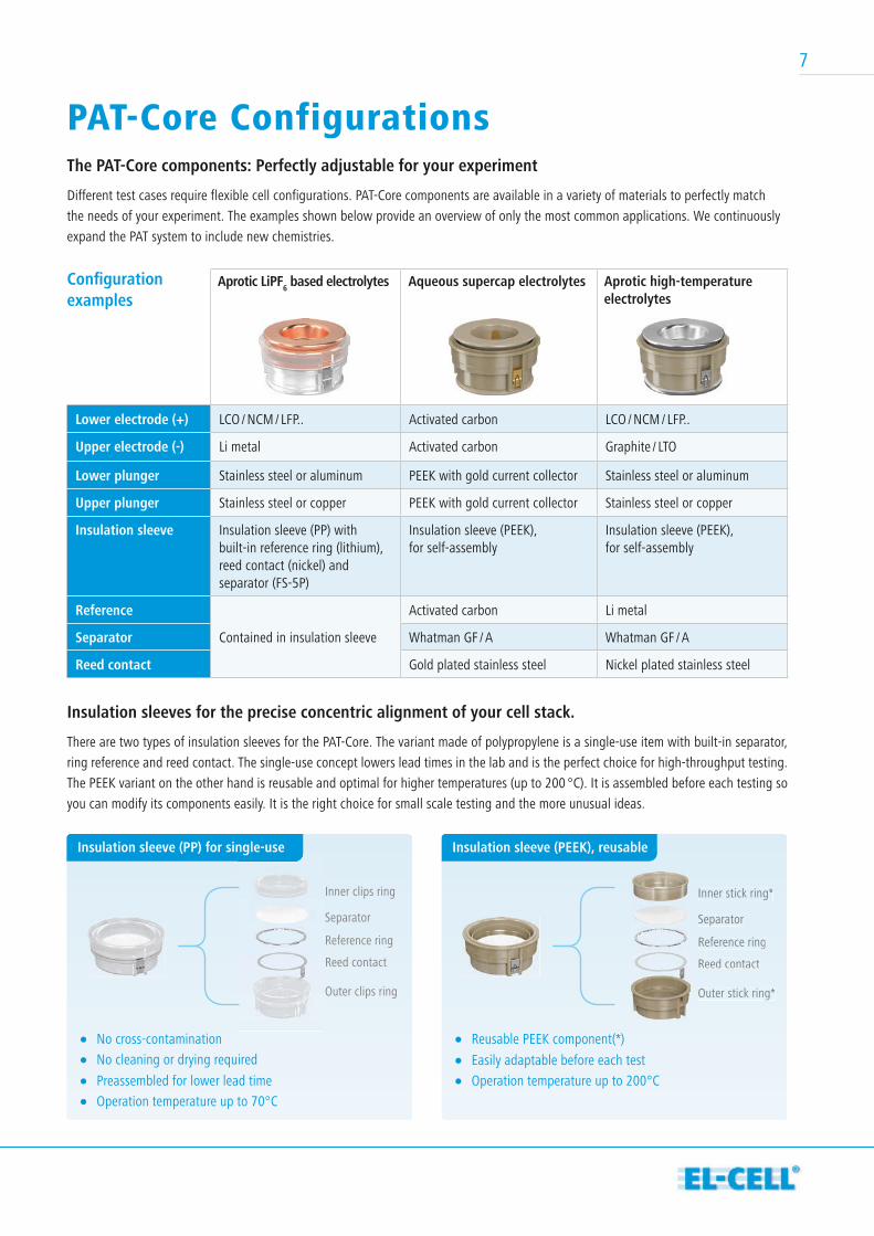
Outer clips ring
Reed contact
Reference ring
Inner clips ring
Separator
Outer stick ring*
Reed contact
Reference ring
Inner stick ring*
Separator
Lower electrode (+) LCO / NCM / LFP.. Activated carbon LCO / NCM / LFP..
Upper electrode (-) Li metal Activated carbon Graphite / LTO
Lower plunger Stainless steel or aluminum PEEK with gold current collector Stainless steel or aluminum
Upper plunger Stainless steel or copper PEEK with gold current collector Stainless steel or copper
Insulation sleeve Insulation sleeve (PP) with built-in reference ring (lithium), reed contact (nickel) and separator (FS-5P)
Insulation sleeve (PEEK), for self-assembly
Insulation sleeve (PEEK), for self-assembly
Reference
Contained in insulation sleeve
Activated carbon Li metal
Separator Whatman GF / A Whatman GF / A
Reed contact Gold plated stainless steel Nickel plated stainless steel
Confi guration examples
The PAT-Core components: Perfectly adjustable for your experiment
Different test cases require flexible cell configurations. PAT-Core components are available in a variety of materials to perfectly match
the needs of your experiment. The examples shown below provide an overview of only the most common applications. We continuously
expand the PAT system to include new chemistries.
Aprotic LiPF6 based electrolytes Aqueous supercap electrolytes Aprotic high-temperature electrolytes
Insulation sleeves for the precise concentric alignment of your cell stack.
There are two types of insulation sleeves for the PAT-Core. The variant made of polypropylene is a single-use item with built-in separator,
ring reference and reed contact. The single-use concept lowers lead times in the lab and is the perfect choice for high-throughput testing.
The PEEK variant on the other hand is reusable and optimal for higher temperatures (up to 200 °C). It is assembled before each testing so
you can modify its components easily. It is the right choice for small scale testing and the more unusual ideas.
Insulation sleeve (PP) for single-use
No cross-contamination No cleaning or drying required
Preassembled for lower lead time Operation temperature up to 70°C
Outer stick ring*
Reed contact
Reference ring
Inner stick ring*
Separator
Insulation sleeve (PEEK), reusable
Reusable PEEK component(*) Easily adaptable before each test Operation temperature up to 200°C
8
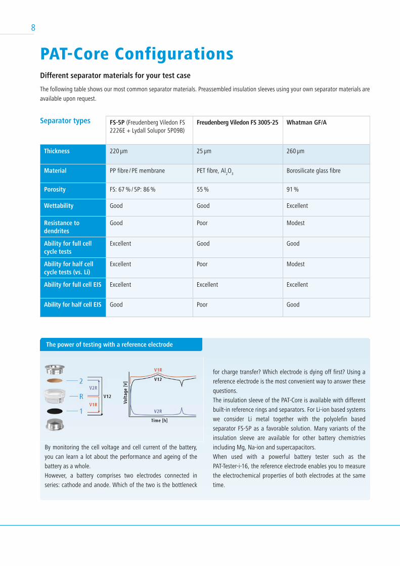
PAT-Core ConfigurationsDifferent separator materials for your test case
The following table shows our most common separator materials. Preassembled insulation sleeves using your own separator materials are
available upon request.
FS-5P (Freudenberg Viledon FS 2226E + Lydall Solupor 5P09B)
Freudenberg Viledon FS 3005-25 Whatman GF/A
Thickness 220 µm 25 µm 260 µm
Material PP fibre / PE membrane PET fibre, Al2O
3Borosilicate glass fibre
Porosity FS: 67 % / 5P: 86 % 55 % 91 %
Wettability Good Good Excellent
Resistance to dendrites
Good Poor Modest
Ability for full cell cycle tests
Excellent Good Good
Ability for half cell cycle tests (vs. Li)
Excellent Poor Modest
Ability for full cell EIS Excellent Excellent Excellent
Ability for half cell EIS Good Poor Good
Separator types
The power of testing with a reference electrode
By monitoring the cell voltage and cell current of the battery,
you can learn a lot about the performance and ageing of the
battery as a whole.
However, a battery comprises two electrodes connected in
series: cathode and anode. Which of the two is the bottleneck
for charge transfer? Which electrode is dying off first? Using a
reference electrode is the most convenient way to answer these
questions.
The insulation sleeve of the PAT-Core is available with different
built-in reference rings and separators. For Li-ion based systems
we consider Li metal together with the polyolefin based
separator FS-5P as a favorable solution. Many variants of the
insulation sleeve are available for other battery chemistries
including Mg, Na-ion and supercapacitors.
When used with a powerful battery tester such as the
PAT-Tester-i-16, the reference electrode enables you to measure
the electrochemical properties of both electrodes at the same
time.
9
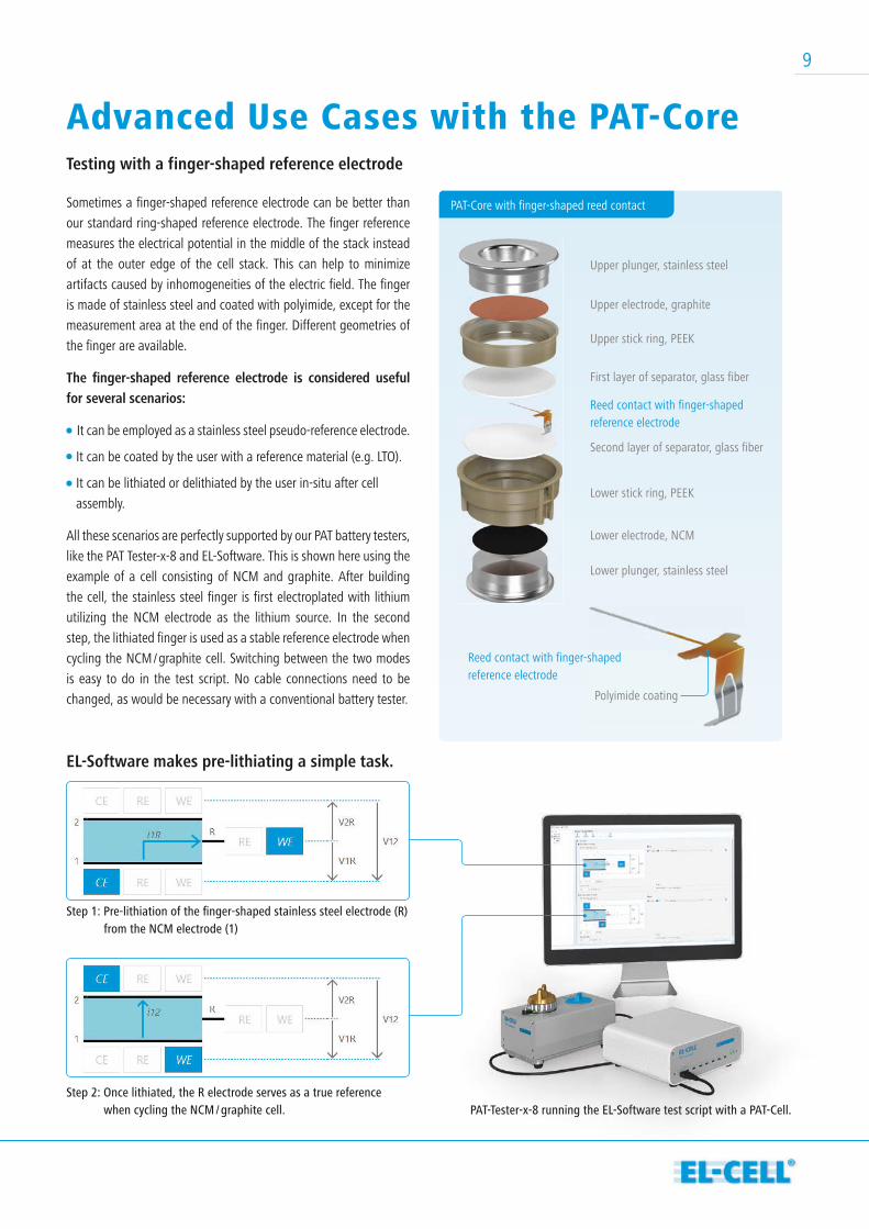
Sometimes a finger-shaped reference electrode can be better than
our standard ring-shaped reference electrode. The finger reference
measures the electrical potential in the middle of the stack instead
of at the outer edge of the cell stack. This can help to minimize
artifacts caused by inhomogeneities of the electric field. The finger
is made of stainless steel and coated with polyimide, except for the
measurement area at the end of the finger. Different geometries of
the finger are available.
The fi nger-shaped reference electrode is considered useful for several scenarios:
It can be employed as a stainless steel pseudo-reference electrode.
It can be coated by the user with a reference material (e.g. LTO).
It can be lithiated or delithiated by the user in-situ after cell
assembly.
All these scenarios are perfectly supported by our PAT battery testers,
like the PAT Tester-x-8 and EL-Software. This is shown here using the
example of a cell consisting of NCM and graphite. After building
the cell, the stainless steel finger is first electroplated with lithium
utilizing the NCM electrode as the lithium source. In the second
step, the lithiated finger is used as a stable reference electrode when
cycling the NCM / graphite cell. Switching between the two modes
is easy to do in the test script. No cable connections need to be
changed, as would be necessary with a conventional battery tester.
EL-Software makes pre-lithiating a simple task.
PAT-Core with finger-shaped reed contact
Advanced Use Cases with the PAT-Core Testing with a finger-shaped reference electrode
Upper plunger, stainless steel
Upper electrode, graphite
Upper stick ring, PEEK
First layer of separator, glass fiber
Reed contact with finger-shapedreference electrode
Reed contact with finger-shapedreference electrode
Second layer of separator, glass fiber
Lower stick ring, PEEK
Lower electrode, NCM
Lower plunger, stainless steel
Polyimide coating
Step 1: Pre-lithiation of the fi nger-shaped stainless steel electrode (R) from the NCM electrode (1)
Step 2: Once lithiated, the R electrode serves as a true reference when cycling the NCM / graphite cell. PAT-Tester-x-8 running the EL-Software test script with a PAT-Cell.
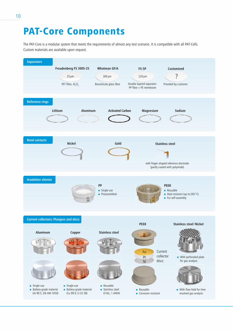
Insulation sleeves
PAT-Core Components The PAT-Core is a modular system that meets the requirements of almost any test scenario. It is compatible with all PAT-Cells.
Custom materials are available upon request.
FS-5P Customized
?Freudenberg FS 3005-25
Lithium Aluminum Activated Carbon Magnesium Sodium
Whatman GF/A
PP
25 µm
PET fibre, Al2O
3Borosilicate glass fibre Provided by customerDouble layered separator:
PP fibre + PE membrane
260 µm 220 µm
Single-use Preassembled
PEEK Reusable Heat resistant (up to 200 °C) For self-assembly
Reference rings
Separators
Gold Stainless steelNickelReed contacts
Single-use Battery grade material
(Cu 99.9, E-CU 58)
Reusable Stainless steel
(316L, 1.4404) Reusable Corrosion resistant
With perforated plate for gas analysis
With flow field for time resolved gas analysis
Au Current collectordiscs
PtNi
Current collectors: Plungers and discs
Aluminum Copper Stainless steel
Stainless steel / NickelPEEK
Single-use Battery grade material
(Al 99.5, EN-AW-1050)
10
with finger-shaped reference electrode(partly coated with polyimide)
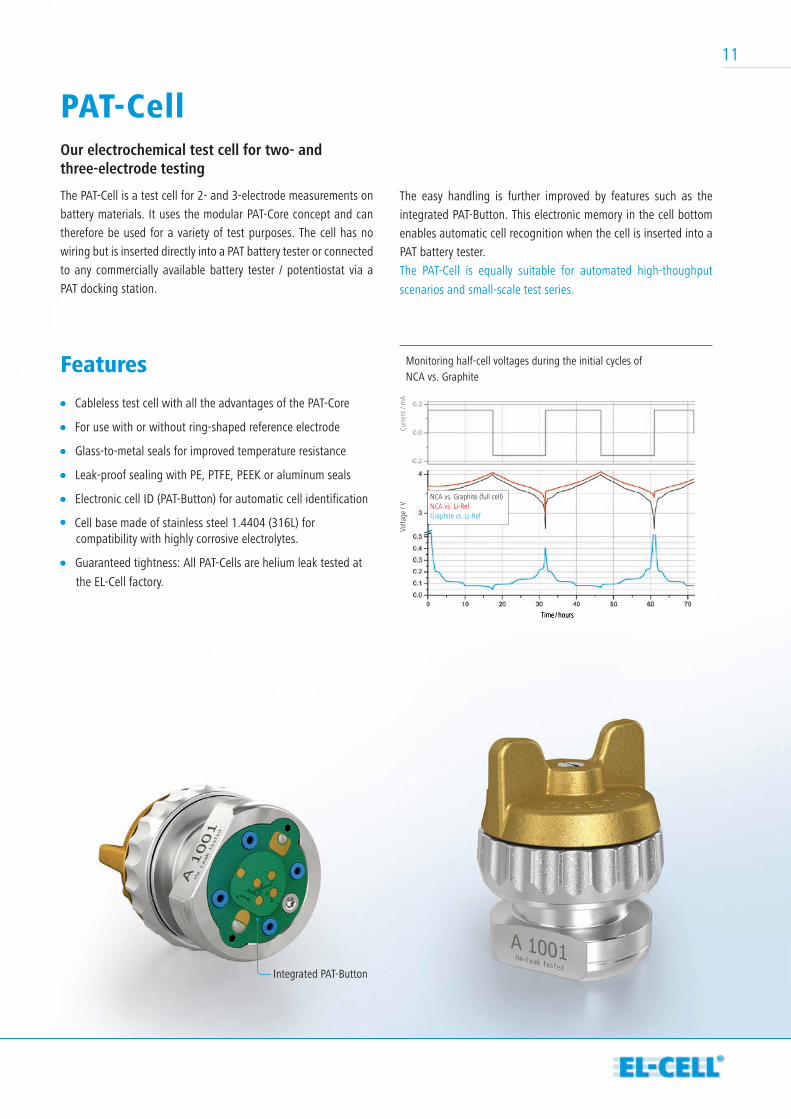
PAT-CellOur electrochemical test cell for two- and three-electrode testing
The PAT-Cell is a test cell for 2- and 3-electrode measurements on
battery materials. It uses the modular PAT-Core concept and can
therefore be used for a variety of test purposes. The cell has no
wiring but is inserted directly into a PAT battery tester or connected
to any commercially available battery tester / potentiostat via a
PAT docking station.
Features
Cableless test cell with all the advantages of the PAT-Core
For use with or without ring-shaped reference electrode
Glass-to-metal seals for improved temperature resistance
Leak-proof sealing with PE, PTFE, PEEK or aluminum seals
Electronic cell ID (PAT-Button) for automatic cell identification
Cell base made of stainless steel 1.4404 (316L) for compatibility with highly corrosive electrolytes.
Guaranteed tightness: All PAT-Cells are helium leak tested at
the EL-Cell factory.
The easy handling is further improved by features such as the
integrated PAT-Button. This electronic memory in the cell bottom
enables automatic cell recognition when the cell is inserted into a
PAT battery tester.
The PAT-Cell is equally suitable for automated high-thoughput
scenarios and small-scale test series.
Volta
ge /
VCu
rrent
/ m
A
Time / hours
NCA vs. Graphite (full cell)
Graphite vs. Li-RefNCA vs. Li-Ref
Monitoring half-cell voltages during the initial cycles of NCA vs. Graphite
Time / hours
Integrated PAT-Button
11
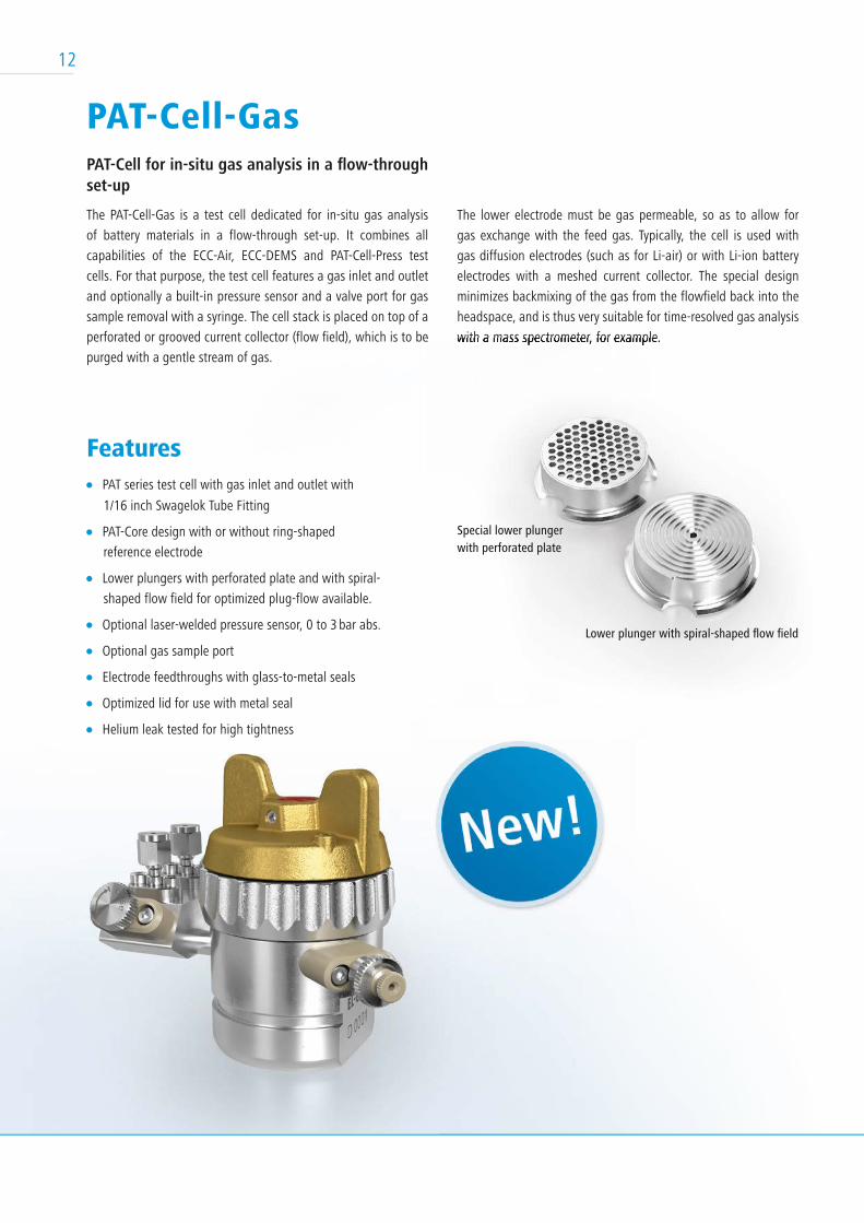
PAT-Cell-GasPAT-Cell for in-situ gas analysis in a fl ow-through set-up
The PAT-Cell-Gas is a test cell dedicated for in-situ gas analysis
of battery materials in a flow-through set-up. It combines all
capabilities of the ECC-Air, ECC-DEMS and PAT-Cell-Press test
cells. For that purpose, the test cell features a gas inlet and outlet
and optionally a built-in pressure sensor and a valve port for gas
sample removal with a syringe. The cell stack is placed on top of a
perforated or grooved current collector (flow field), which is to be
purged with a gentle stream of gas.
Features PAT series test cell with gas inlet and outlet with
1/16 inch Swagelok Tube Fitting
PAT-Core design with or without ring-shaped
reference electrode
Lower plungers with perforated plate and with spiral-
shaped flow field for optimized plug-flow available.
Optional laser-welded pressure sensor, 0 to 3 bar abs.
Optional gas sample port
Electrode feedthroughs with glass-to-metal seals
Optimized lid for use with metal seal
Helium leak tested for high tightness
The lower electrode must be gas permeable, so as to allow for
gas exchange with the feed gas. Typically, the cell is used with
gas diffusion electrodes (such as for Li-air) or with Li-ion battery
electrodes with a meshed current collector. The special design
minimizes backmixing of the gas from the flowfield back into the
headspace, and is thus very suitable for time-resolved gas analysis
with a mass spectrometer, for example. perforated or grooved current collector (flow field), which is to be with a mass spectrometer, for example.
Special lower plungerwith perforated plate
Lower plunger with spiral-shaped fl ow fi eld
12
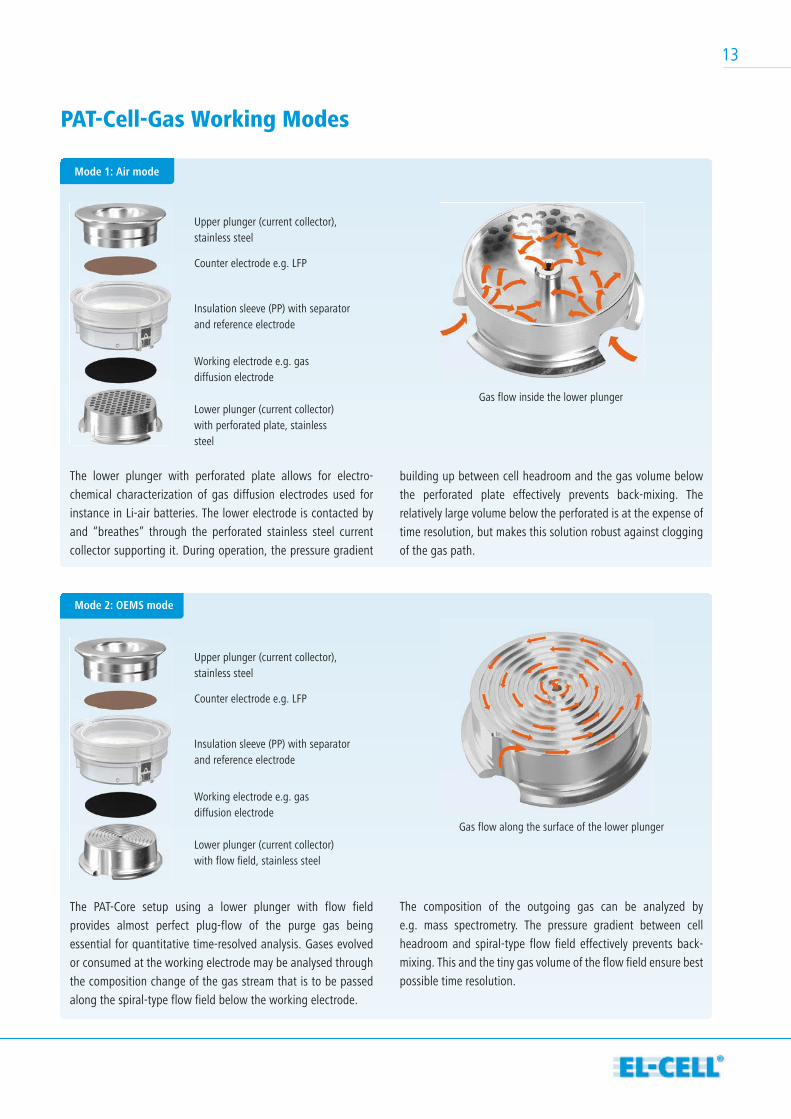
The lower plunger with perforated plate allows for electro-
chemical characterization of gas diffusion electrodes used for
instance in Li-air batteries. The lower electrode is contacted by
and “breathes” through the perforated stainless steel current
collector supporting it. During operation, the pressure gradient
PAT-Cell-Gas Working Modes
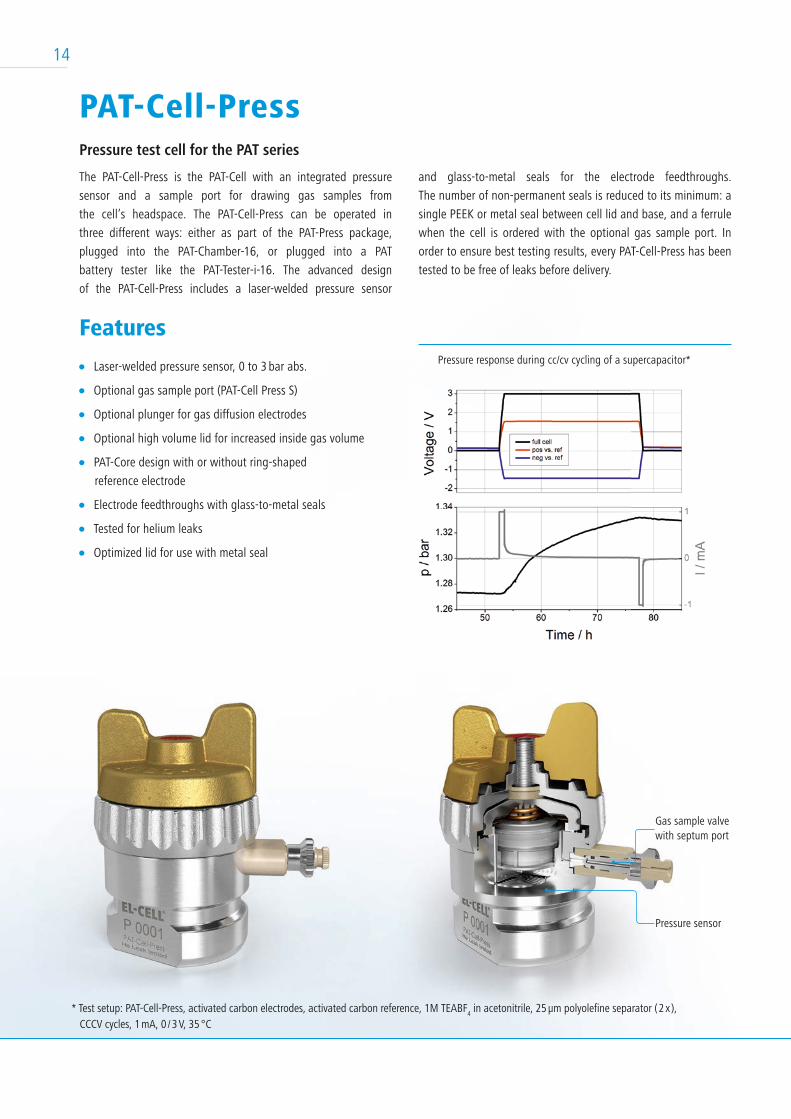
The PAT-Core setup using a lower plunger with flow field
provides almost perfect plug-flow of the purge gas being
essential for quantitative time-resolved analysis. Gases evolved
or consumed at the working electrode may be analysed through
the composition change of the gas stream that is to be passed
along the spiral-type flow field below the working electrode.
building up between cell headroom and the gas volume below
the perforated plate effectively prevents back-mixing. The
relatively large volume below the perforated is at the expense of
time resolution, but makes this solution robust against clogging
of the gas path.
The composition of the outgoing gas can be analyzed by
e.g. mass spectrometry. The pressure gradient between cell
headroom and spiral-type flow field effectively prevents back-
mixing. This and the tiny gas volume of the flow field ensure best
possible time resolution.
Upper plunger (current collector), stainless steel
Upper plunger (current collector), stainless steel
Counter electrode e.g. LFP
Counter electrode e.g. LFP
Insulation sleeve (PP) with separator and reference electrode
Insulation sleeve (PP) with separator and reference electrode
Working electrode e.g. gas diffusion electrode
Working electrode e.g. gas diffusion electrode
Gas flow inside the lower plunger
Mode 1: Air mode
Gas flow along the surface of the lower plunger
Lower plunger (current collector) with perforated plate, stainless steel
Lower plunger (current collector) with flow field, stainless steel
Mode 2: OEMS mode
13
PAT-Cell-PressPressure test cell for the PAT series
The PAT-Cell-Press is the PAT-Cell with an integrated pressure
sensor and a sample port for drawing gas samples from
the cell’s headspace. The PAT-Cell-Press can be operated in
three different ways: either as part of the PAT-Press package,
plugged into the PAT-Chamber-16, or plugged into a PAT
battery tester like the PAT-Tester-i- 16. The advanced design
of the PAT-Cell-Press includes a laser-welded pressure sensor
Features
Laser-welded pressure sensor, 0 to 3 bar abs.
Optional gas sample port (PAT-Cell Press S)
Optional plunger for gas diffusion electrodes
Optional high volume lid for increased inside gas volume
PAT-Core design with or without ring-shaped
reference electrode
Electrode feedthroughs with glass-to-metal seals
Tested for helium leaks
Optimized lid for use with metal seal
and glass-to-metal seals for the electrode feedthroughs.
The number of non-permanent seals is reduced to its minimum: a
single PEEK or metal seal between cell lid and base, and a ferrule
when the cell is ordered with the optional gas sample port. In
order to ensure best testing results, every PAT-Cell-Press has been
tested to be free of leaks before delivery.
Pressure sensor
Gas sample valvewith septum port
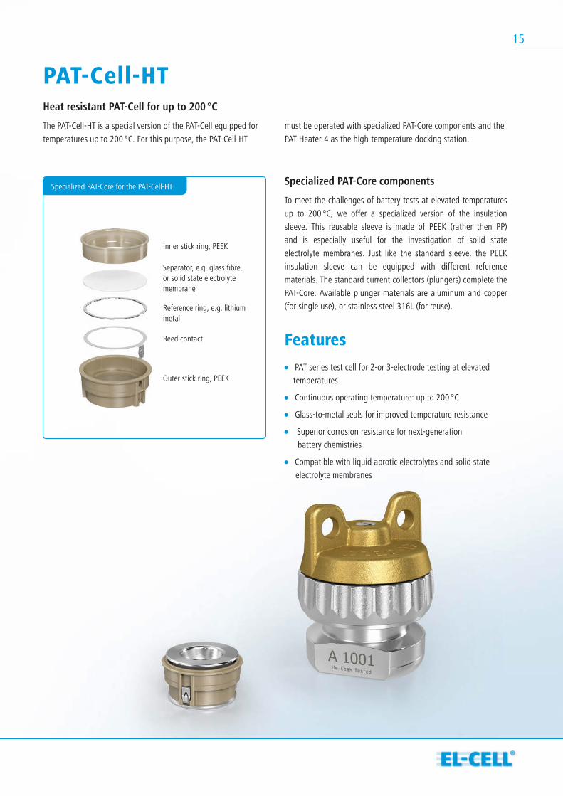
Pressure response during cc/cv cycling of a supercapacitor*
* Test setup: PAT-Cell-Press, activated carbon electrodes, activated carbon reference, 1M TEABF4 in acetonitrile, 25 µm polyolefine separator ( 2 x ),
CCCV cycles, 1 mA, 0 / 3 V, 35 °C
14
Specialized PAT-Core components
To meet the challenges of battery tests at elevated temperatures
up to 200 °C, we offer a specialized version of the insulation
sleeve. This reusable sleeve is made of PEEK (rather then PP)
and is especially useful for the investigation of solid state
electrolyte membranes. Just like the standard sleeve, the PEEK
insulation sleeve can be equipped with different reference
materials. The standard current collectors (plungers) complete the
PAT-Core. Available plunger materials are aluminum and copper
(for single use), or stain less steel 316L (for reuse).
Features
PAT series test cell for 2-or 3-electrode testing at elevated
temperatures
Continuous operating temperature: up to 200 °C
Glass-to-metal seals for improved temperature resistance
Superior corrosion resistance for next-generation
battery chemistries
Compatible with liquid aprotic electrolytes and solid state
electrolyte membranes
PAT-Cell-HTHeat resistant PAT-Cell for up to 200 °C
The PAT-Cell-HT is a special version of the PAT-Cell equipped for
temperatures up to 200 °C. For this purpose, the PAT-Cell-HT
must be operated with specialized PAT-Core components and the
PAT-Heater-4 as the high-temperature docking station.
Schematic view of a connected PAT-Stand-16Specialized PAT-Core for the PAT-Cell-HT
Outer stick ring, PEEK
Reed contact
Reference ring, e.g. lithium metal
Separator, e.g. glass fibre,or solid state electrolyte membrane
Inner stick ring, PEEK
15
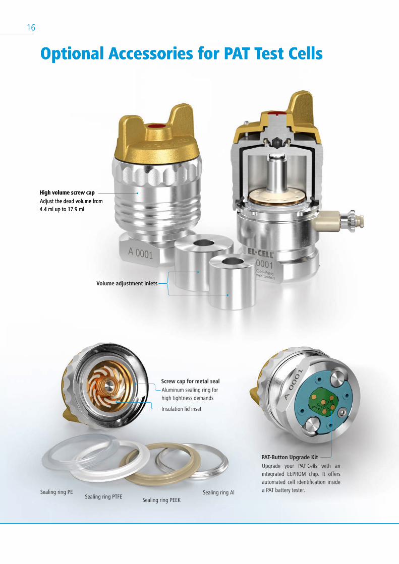
Optional Accessories for PAT Test Cells
Sealing ring PESealing ring PTFE Sealing ring PEEK
Sealing ring Al
Aluminum sealing ring for high tightness demands
Upgrade your PAT-Cells with an integrated EEPROM chip. It offers automated cell identification inside a PAT battery tester.
Adjust the dead volume from4.4 ml up to 17.9 ml
Insulation lid inset
Screw cap for metal seal
PAT-Button Upgrade Kit
High volume screw cap
Optional Accessories for PAT Test Cells
Adjust the dead volume from4.4 ml up to 17.9 ml
High volume screw cap
Volume adjustment inlets
16
Features
Socket for one PAT series test cell (charge / discharge / EIS
compatible, please refer to the PAT-Compatibility table)
Compatible with any potentiostat and battery tester
Can be used inside a glove box environment
Fits into tight spaces
Flexible wiring via 2 mm banana sockets
Saves wiring effort and space in the lab
Technical Specifications
Width x depth: 80 mm x 62 mm
Height: 21 / 83 mm (without / with PAT-Cell-Press)
Weight: 0.12 kg (without PAT-Cell)
The PAT-Clamp-1 allows immediate functional testing of all PAT
series test cells with smallest possible footprint. The PAT-Clamp-1 is
often used in addition to a high-throughput solution. For instance,
16 PAT-Cells can be cycled in parallel in a PAT-Chamber-16
connected by a third-party battery tester without impedance
capability. In that case, the impedance of each test cell can be
measured before and after the cycle test in the PAT-Clamp-1
connected to the PAT-Tester-x or another impedance analyser.
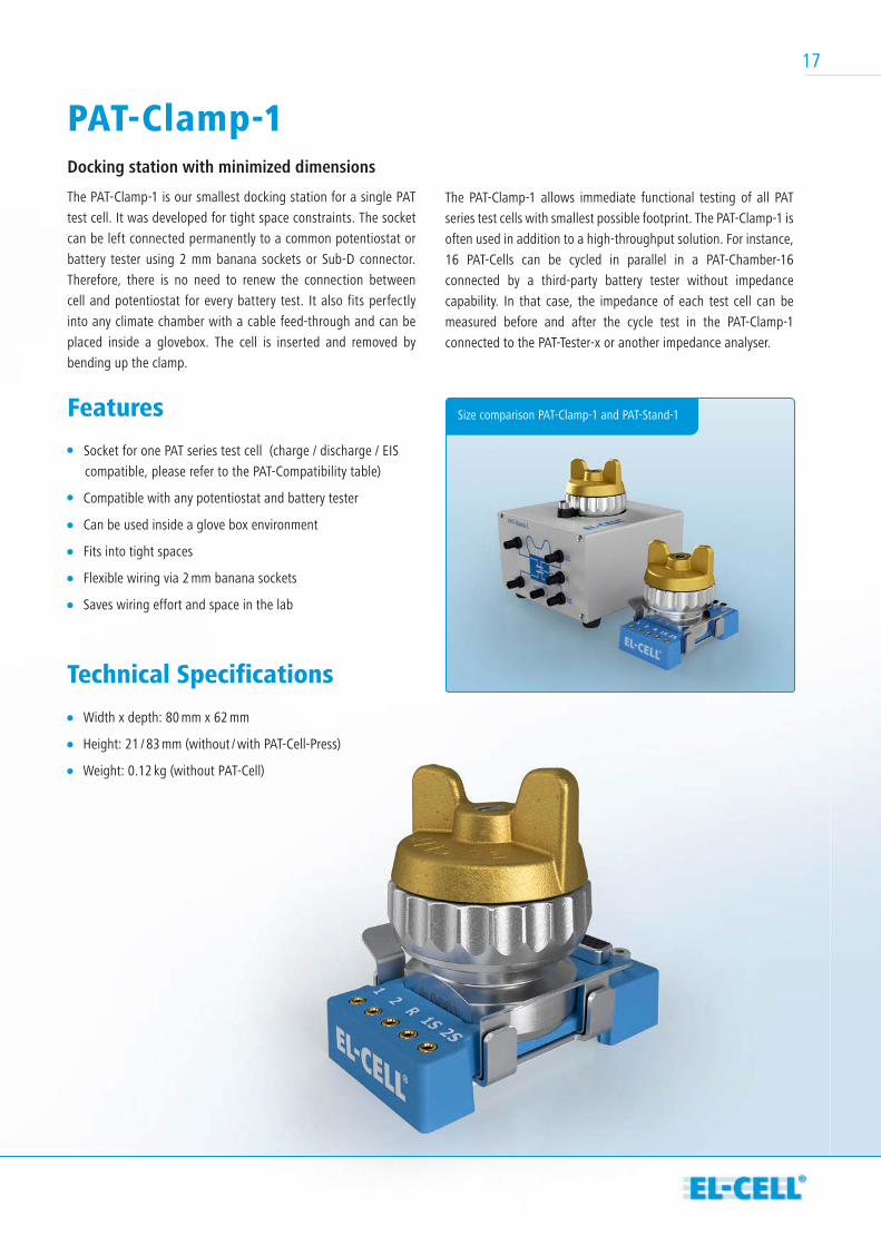
PAT-Clamp-1Docking station with minimized dimensions
The PAT-Clamp-1 is our smallest docking station for a single PAT
test cell. It was developed for tight space constraints. The socket
can be left connected permanently to a common potentiostat or
battery tester using 2 mm banana sockets or Sub-D connector.
Therefore, there is no need to renew the connection between
cell and potentiostat for every battery test. It also fits perfectly
into any climate chamber with a cable feed-through and can be
placed inside a glovebox. The cell is inserted and removed by
bending up the clamp.
Size comparison PAT-Clamp-1 and PAT-Stand-1
17
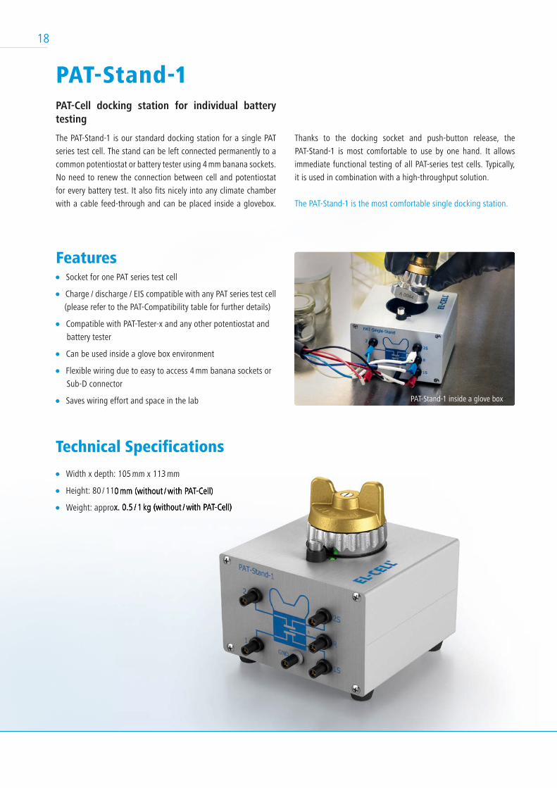
PAT-Stand-1PAT-Cell docking station for individual battery testing
The PAT-Stand-1 is our standard docking station for a single PAT
series test cell. The stand can be left connected permanently to a
common potentiostat or battery tester using 4 mm banana sockets.
No need to renew the connection between cell and potentiostat
for every battery test. It also fits nicely into any climate chamber
with a cable feed-through and can be placed inside a glovebox.
Features Socket for one PAT series test cell
Charge / discharge / EIS compatible with any PAT series test cell
(please refer to the PAT-Compatibility table for further details)
Compatible with PAT-Tester-x and any other potentiostat and
battery tester
Can be used inside a glove box environment
Flexible wiring due to easy to access 4 mm banana sockets or
Sub-D connector
Saves wiring effort and space in the lab
Technical Specifications
Width x depth: 105 mm x 113 mm
Height: 80 / 110 mm (without / with PAT-Cell)
Weight: approx. 0.5 / 1 kg (without / with PAT-Cell)
Thanks to the docking socket and push-button release, the
PAT-Stand-1 is most comfortable to use by one hand. It allows
immediate functional testing of all PAT-series test cells. Typically,
it is used in combination with a high-throughput solution.
The PAT-Stand-1 is the most comfortable single docking station.
PAT-Stand-1 inside a glove box
idth x depth: 105 mm x 113 mm
Height: 80 / 110 mm (without / with PAT-Cell)
Weight: approx. 0.5 / 1 kg (without / with PAT-Cell)
18
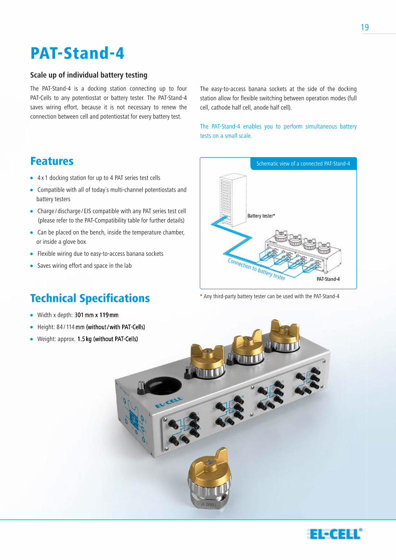
PAT-Stand-4Scale up of individual battery testing
The PAT-Stand-4 is a docking station connecting up to four
PAT-Cells to any potentiostat or battery tester. The PAT-Stand-4
saves wiring effort, because it is not necessary to renew the
connection between cell and potentiostat for every battery test.
Features 4 x 1 docking station for up to 4 PAT series test cells
Compatible with all of today´s multi-channel potentiostats and
battery testers
Charge / discharge / EIS compatible with any PAT series test cell
(please refer to the PAT-Compatibility table for further details)
Can be placed on the bench, inside the temperature chamber,
or inside a glove box
Flexible wiring due to easy-to-access banana sockets
Saves wiring effort and space in the lab
Technical Specifications Width x depth: 301 mm x 119 mm
Height: 84 / 114 mm (without / with PAT-Cells)
Weight: approx. 1.5 kg (without PAT-Cells)
The easy-to-access banana sockets at the side of the docking
station allow for flexible switching between operation modes (full
cell, cathode half cell, anode half cell).
The PAT-Stand-4 enables you to perform simultaneous battery
tests on a small scale.
Width x depth: 301 mm x 119 mm
Height: 84 / 114 mm (without / with PAT-Cells)
Weight: approx. 1.5 kg (without PAT-Cells)
* Any third-party battery tester can be used with the PAT-Stand-4
Schematic view of a connected PAT-Stand-4
19
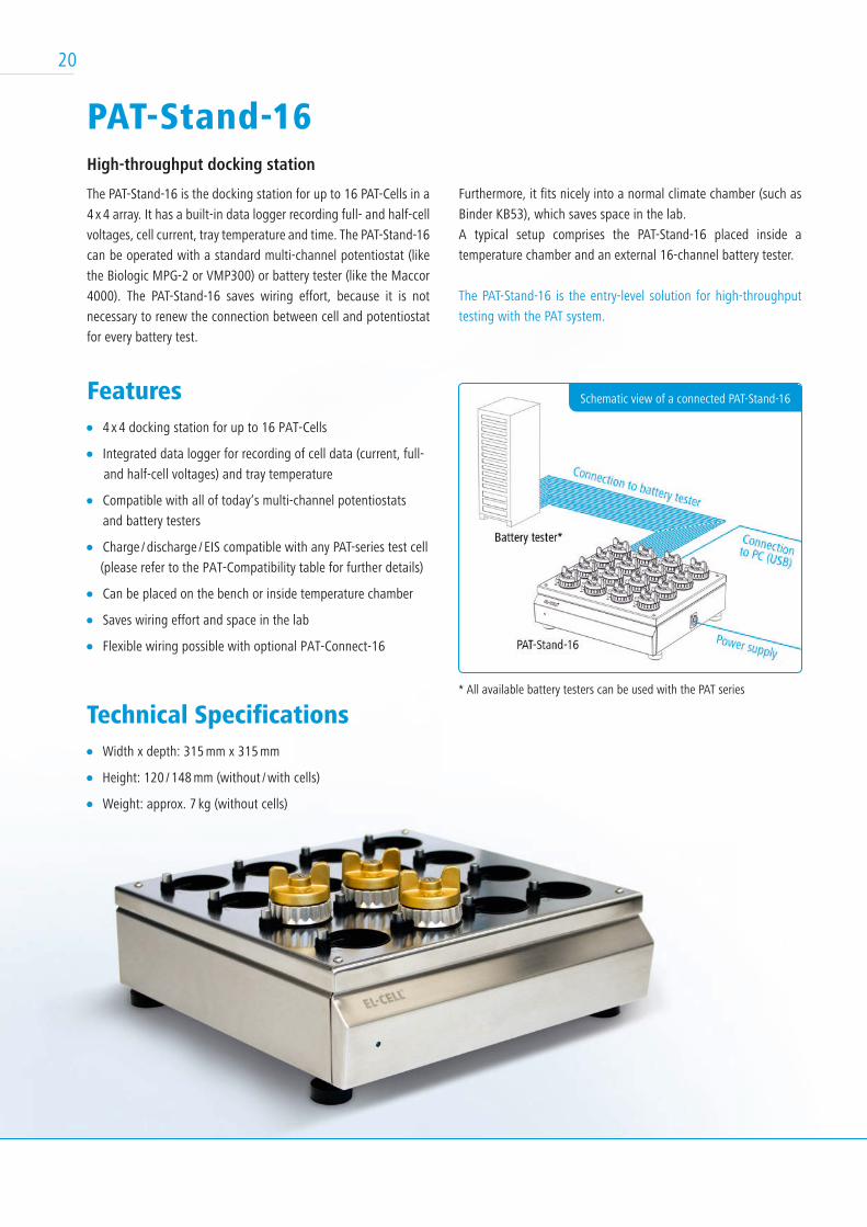
PAT-Stand-16High-throughput docking station
The PAT-Stand-16 is the docking station for up to 16 PAT-Cells in a
4 x 4 array. It has a built-in data logger recording full- and half-cell
voltages, cell current, tray temperature and time. The PAT-Stand-16
can be operated with a standard multi-channel potentiostat (like
the Biologic MPG-2 or VMP300) or battery tester (like the Maccor
4000). The PAT-Stand-16 saves wiring effort, because it is not
necessary to renew the connection between cell and potentiostat
for every battery test.
Features 4 x 4 docking station for up to 16 PAT-Cells
Integrated data logger for recording of cell data (current, full-
and half-cell voltages) and tray temperature
Compatible with all of today‘s multi-channel potentiostats
and battery testers
Charge / discharge / EIS compatible with any PAT-series test cell
(please refer to the PAT-Compatibility table for further details)
Can be placed on the bench or inside temperature chamber
Saves wiring effort and space in the lab
Flexible wiring possible with optional PAT-Connect-16
Technical Specifications Width x depth: 315 mm x 315 mm
Height: 120 / 148 mm (without / with cells)
Weight: approx. 7 kg (without cells)
Furthermore, it fits nicely into a normal climate chamber (such as
Binder KB53), which saves space in the lab.
A typical setup comprises the PAT-Stand-16 placed inside a
temperature chamber and an external 16-channel battery tester.
The PAT-Stand-16 is the entry-level solution for high-throughput
testing with the PAT system.
* All available battery testers can be used with the PAT series
Schematic view of a connected PAT-Stand-16
20
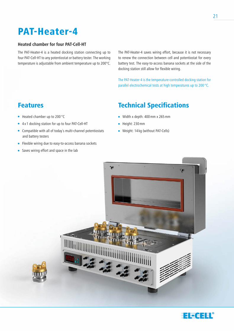
Features
Heated chamber up to 200 °C
4 x 1 docking station for up to four PAT-Cell-HT
Compatible with all of today´s multi-channel potentiostats
and battery testers
Flexible wiring due to easy-to-access banana sockets
Saves wiring effort and space in the lab
Technical Specifications
Width x depth: 400 mm x 265 mm
Height: 230 mm
Weight: 14 kg (without PAT-Cells)
The PAT-Heater-4 saves wiring effort, because it is not necessary
to renew the connection between cell and potentiostat for every
battery test. The easy-to-access banana sockets at the side of the
docking station still allow for flexible wiring.
The PAT-Heater-4 is the temperature-controlled docking station for
parallel electrochemical tests at high temperatures up to 200 °C.
PAT-Heater-4Heated chamber for four PAT-Cell-HT
The PAT-Heater-4 is a heated docking station connecting up to
four PAT-Cell-HT to any potentiostat or battery tester. The working
temperature is adjustable from ambient temperature up to 200°C.
21
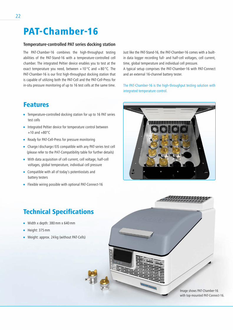
Features Temperature-controlled docking station for up to 16 PAT series
test cells
Integrated Peltier device for temperature control between
+10 and +80°C
Ready for PAT-Cell-Press for pressure monitoring
Charge / discharge / EIS compatible with any PAT-series test cell
(please refer to the PAT-Compatibility table for further details)
With data acquisition of cell current, cell voltage, half-cell
voltages, global temperature, individual cell pressure
Compatible with all of today‘s potentiostats and
battery testers
Flexible wiring possible with optional PAT-Connect-16
Technical Specifications
Width x depth: 380 mm x 640 mm
Height: 375 mm
Weight: approx. 24 kg (without PAT-Cells)
Just like the PAT-Stand-16, the PAT-Chamber-16 comes with a built-
in data logger recording full- and half-cell voltages, cell current,
time, global temperature and individual cell pressure.
A typical setup comprises the PAT-Chamber-16 with PAT-Connect
and an external 16-channel battery tester.
The PAT-Chamber-16 is the high-throughput testing solution with
integrated temperature control.
PAT-Chamber-16 Temperature-controlled PAT series docking station
The PAT-Chamber-16 combines the high-throughput testing
abilities of the PAT-Stand-16 with a temperature-controlled cell
chamber. The integrated Peltier device enables you to test at the
exact temperature you need, between + 10 °C and + 80 °C. The
PAT-Chamber-16 is our first high-throughput docking station that
is capable of utilizing both the PAT-Cell and the PAT-Cell-Press for
in-situ pressure monitoring of up to 16 test cells at the same time.
Image shows PAT-Chamber-16with top-mounted PAT-Connect-16.
22
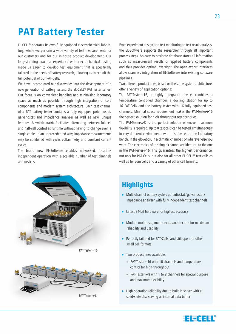
Highlights Multi-channel battery cycler / potentiostat / galvanostat /
impedance analyser with fully independent test channels
Latest 24-bit hardware for highest accuracy
Modern multi-user, multi-device architecture for maximum
reliability and usability
Perfectly tailored for PAT-Cells, and still open for other
small cell formats
Two product lines available:
PAT-Tester-i-16 with 16 channels and temperature
control for high-throughput
PAT-Tester-x-8 with 1 to 8 channels for special purpose
and maximum flexibility
High operation reliability due to built-in server with a
solid-state disc serving as internal data buffer
From experiment design and test monitoring to test result analysis,
the EL-Software supports the researcher through all important
process steps. An easy-to-navigate database stores all information
such as measurement results or applied battery components
and thus provides optimal oversight. The open export interfaces
allow seamless integration of EL-Software into existing software
pipelines.
Two different product lines, based on the same system architecture,
offer a variety of application options:
The PAT-Tester-i-16, a highly integrated device, combines a
temperature controlled chamber, a docking station for up to
16 PAT-Cells and the battery tester with 16 fully equipped test
channels. Minimal space requirement makes the PAT-Tester-i-16
the perfect solution for high-throughput test scenarios.
The PAT-Tester-x-8 is the perfect solution whenever maximum
flexibility is required. Up to 8 test cells can be tested simultaneously
in very different environments with this device: on the laboratory
bench, in the glovebox, in a climatic chamber, or wherever else you
want. The electronics of the single channel are identical to the one
in the PAT-Tester-i-16. This guarantees the highest performance,
not only for PAT-Cells, but also for all other EL-CELL® test cells as
well as for coin cells and a variety of other cell formats.
PAT Battery Tester EL-CELL® operates its own fully equipped electrochemical labora-
tory, where we perform a wide variety of test measurements for
our customers and for our in-house product development. Our
long-standing practical experience with electrochemical testing
made us eager to develop test equipment that is specifically
tailored to the needs of battery research, allowing us to exploit the
full potential of our PAT-Cells.
We have incorporated our discoveries into the development of a
new generation of battery testers, the EL-CELL® PAT tester series.
Our focus is on convenient handling and minimising laboratory
space as much as possible through high integration of core
components and modern system architecture. Each test channel
of a PAT battery tester contains a fully equipped potentiostat/
galvanostat and impedance analyser as well as new, unique
features. A switch matrix facilitates alternating between full-cell
and half-cell control at runtime without having to change even a
single cable. In an unprecedented way, impedance measurements
may be combined with cyclic voltammetry and constant current
cycles.
The brand new EL-Software enables networked, location-
independent operation with a scalable number of test channels
and devices.
PAT-Tester-i-16
PAT-Tester-x-8
23
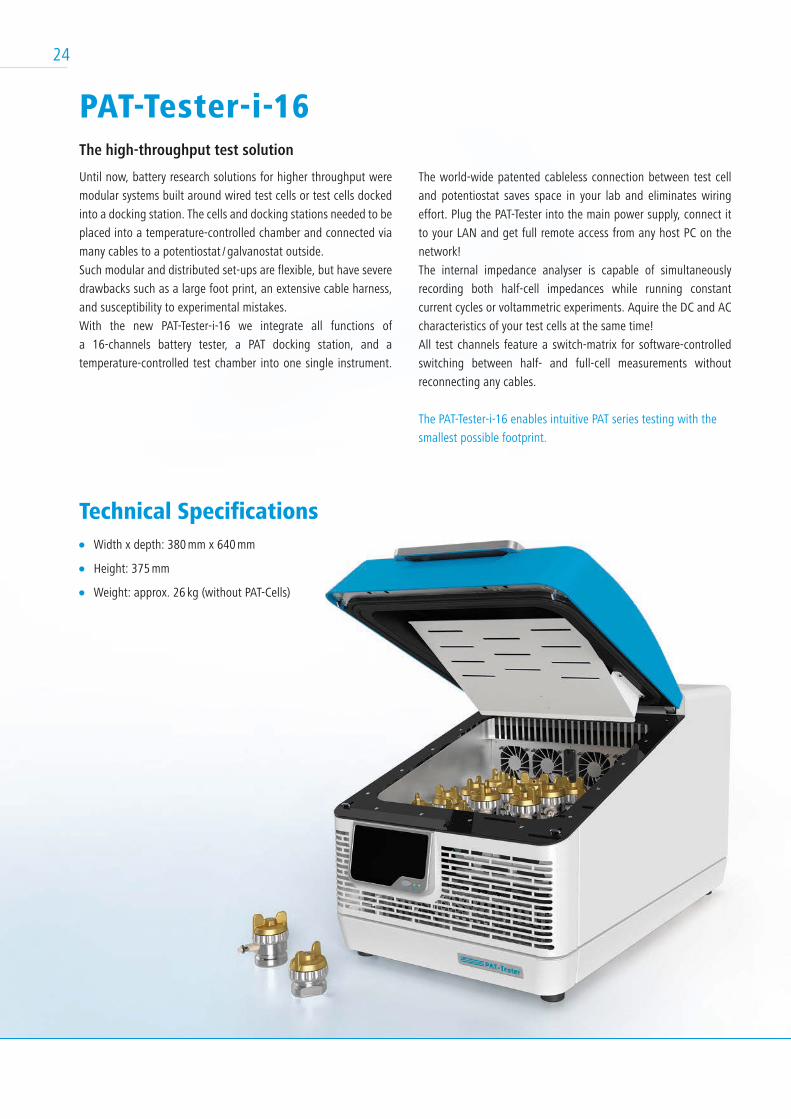
PAT-Tester-i-16The high-throughput test solution
Until now, battery research solutions for higher throughput were
modular systems built around wired test cells or test cells docked
into a docking station. The cells and docking stations needed to be
placed into a temperature-controlled chamber and connected via
many cables to a potentiostat / galvanostat outside.
Such modular and distributed set-ups are flexible, but have severe
drawbacks such as a large foot print, an extensive cable harness,
and susceptibility to experimental mistakes.
With the new PAT-Tester-i-16 we integrate all functions of
a 16-channels battery tester, a PAT docking station, and a
temperature-controlled test chamber into one single instrument.
The world-wide patented cableless connection between test cell
and potentiostat saves space in your lab and eliminates wiring
effort. Plug the PAT-Tester into the main power supply, connect it
to your LAN and get full remote access from any host PC on the
network!
The internal impedance analyser is capable of simultaneously
recording both half-cell impedances while running constant
current cycles or voltammetric experiments. Aquire the DC and AC
characteristics of your test cells at the same time!
All test channels feature a switch-matrix for software-controlled
switching between half- and full-cell measurements without
reconnecting any cables.
The PAT-Tester-i-16 enables intuitive PAT series testing with the
smallest possible footprint.
24
Technical Specifications Width x depth: 380 mm x 640 mm
Height: 375 mm
Weight: approx. 26 kg (without PAT-Cells)
25
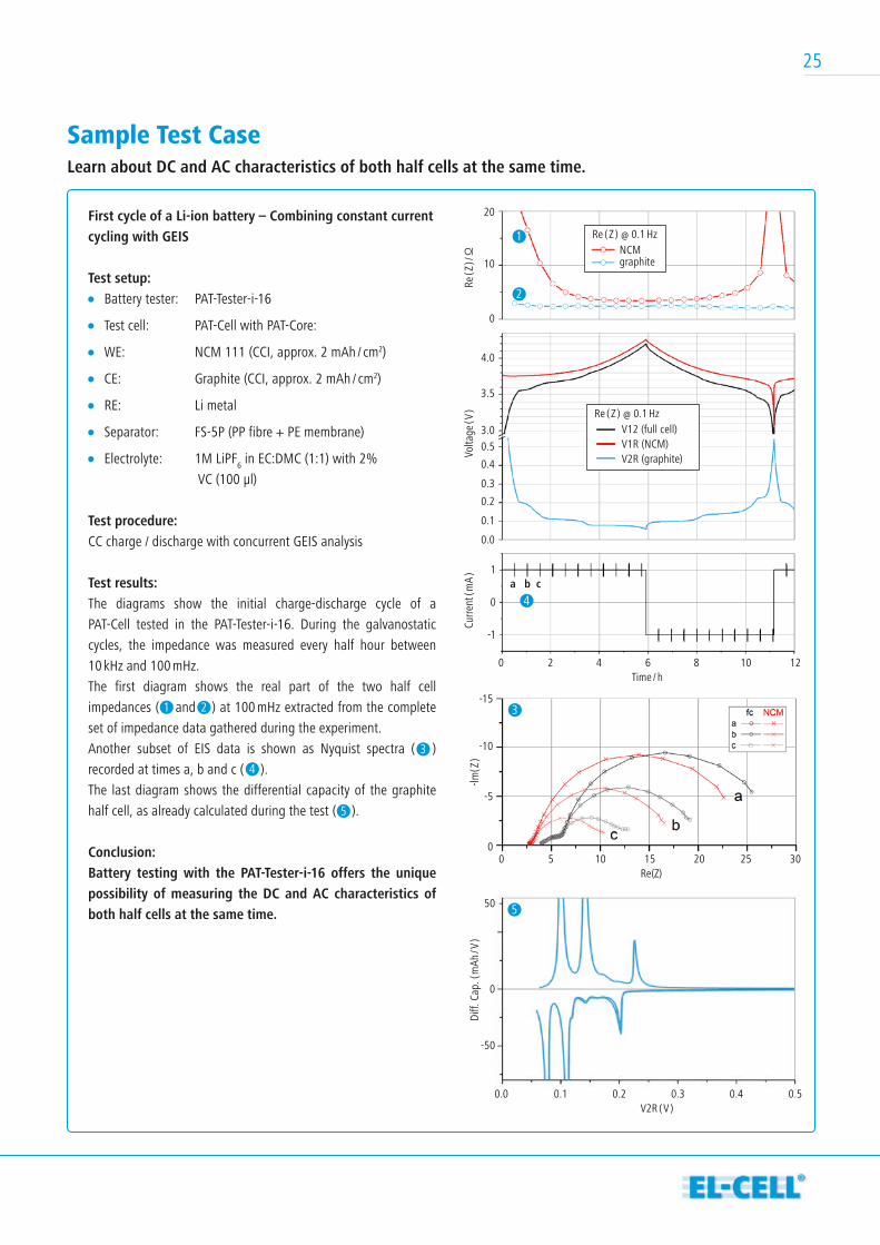
Sample Test Case Learn about DC and AC characteristics of both half cells at the same time.
First cycle of a Li-ion battery – Combining constant current cycling with GEIS
Test setup: Battery tester: PAT-Tester-i-16
Test cell: PAT-Cell with PAT-Core:
WE: NCM 111 (CCI, approx. 2 mAh / cm2)
CE: Graphite (CCI, approx. 2 mAh / cm2)
RE: Li metal
Separator: FS-5P (PP fibre + PE membrane)
Electrolyte: 1M LiPF6 in EC:DMC (1:1) with 2%
VC (100 µl)
Test procedure:CC charge / discharge with concurrent GEIS analysis
Test results:The diagrams show the initial charge-discharge cycle of a
PAT-Cell tested in the PAT-Tester-i-16. During the galvanostatic
cycles, the impedance was measured every half hour between
10 kHz and 100 mHz.
The first diagram shows the real part of the two half cell
impedances ( and ) at 100 mHz extracted from the complete
set of impedance data gathered during the experiment.
Another subset of EIS data is shown as Nyquist spectra ( )
recorded at times a, b and c ( ).
The last diagram shows the differential capacity of the graphite
half cell, as already calculated during the test ( ).
Conclusion:Battery testing with the PAT-Tester-i-16 offers the unique possibility of measuring the DC and AC characteristics of both half cells at the same time.
Re(Z)
-lm( Z
)
0 5 10 15 20 25 30
-15
-10
-5
0
V2R ( V )
Diff.
Cap
. ( m
Ah / V
)
0.0 0.1 0.2 0.3 0.4 0.5
50
0
-50
Time / h
Re ( Z
) / Ω
Volta
ge ( V
)Cu
rrent
( mA
)
0 2 4 6 8 10 12
20
10
0
1
0
-1
4.0
3.5
3.00.5
0.4
0.3
0.2
0.1
0.0
NCMgraphite
Re ( Z ) @ 0.1 Hz
V12 (full cell)V1R (NCM)V2R (graphite)
Re ( Z ) @ 0.1 Hz
a b c
1
1
2
2 3
3
4
5
5
4
26
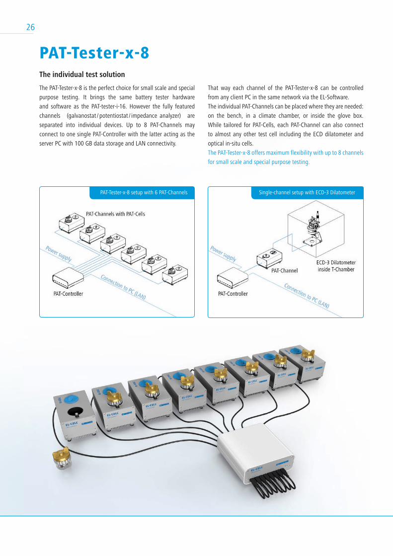
Single-channel setup with ECD-3 DilatometerPAT-Tester-x-8 setup with 6 PAT-Channels
PAT-Tester-x-8The individual test solution
The PAT-Tester-x-8 is the perfect choice for small scale and special
purpose testing. It brings the same battery tester hardware
and software as the PAT-tester-i-16. However the fully featured
channels (galvanostat / potentiostat / impedance analyzer) are
separated into individual devices. Up to 8 PAT-Channels may
connect to one single PAT-Controller with the latter acting as the
server PC with 100 GB data storage and LAN connectivity.
That way each channel of the PAT-Tester-x-8 can be controlled
from any client PC in the same network via the EL-Software.
The individual PAT-Channels can be placed where they are needed:
on the bench, in a climate chamber, or inside the glove box.
While tailored for PAT-Cells, each PAT-Channel can also connect
to almost any other test cell including the ECD dilatometer and
optical in-situ cells.
The PAT-Tester-x-8 offers maximum flexibility with up to 8 channels
for small scale and special purpose testing.
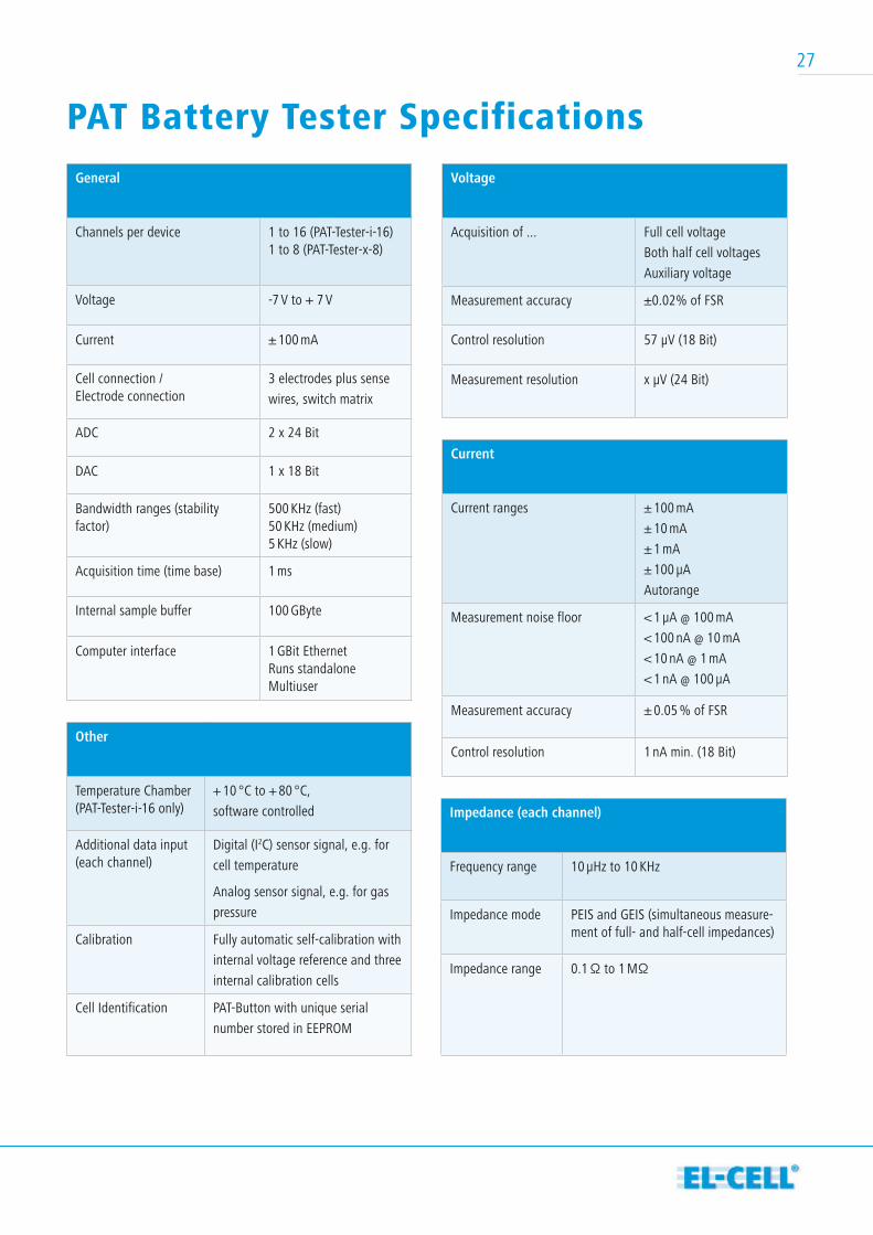
General
Channels per device 1 to 16 (PAT-Tester-i-16)1 to 8 (PAT-Tester-x-8)
Voltage -7 V to + 7 V
Current ± 100 mA
Cell connection / Electrode connection
3 electrodes plus sense
wires, switch matrix
ADC 2 x 24 Bit
DAC 1 x 18 Bit
Bandwidth ranges (stability factor)
500 KHz (fast)50 KHz (medium)5 KHz (slow)
Acquisition time (time base) 1 ms
Internal sample buffer 100 GByte
Computer interface 1 GBit EthernetRuns standaloneMultiuser
PAT Battery Tester Specifications Voltage
Acquisition of ... Full cell voltage
Both half cell voltages
Auxiliary voltage
Measurement accuracy ±0.02% of FSR
Control resolution 57 µV (18 Bit)
Measurement resolution x µV (24 Bit)
Current
Current ranges ± 100 mA
± 10 mA
± 1 mA
± 100 µA
Autorange
Measurement noise floor < 1 µA @ 100 mA
< 100 nA @ 10 mA
< 10 nA @ 1 mA
< 1 nA @ 100 µA
Measurement accuracy ± 0.05 % of FSR
Control resolution 1 nA min. (18 Bit)
Impedance (each channel)
Frequency range 10 µHz to 10 KHz
Impedance mode PEIS and GEIS (simultaneous measure-ment of full- and half-cell impedances)
Impedance range 0.1 Ω to 1 MΩ
Other
Temperature Chamber(PAT-Tester-i-16 only)
+ 10 °C to + 80 °C,
software controlled
Additional data input (each channel)
Digital (I2C) sensor signal, e.g. for
cell temperature
Analog sensor signal, e.g. for gas
pressure
Calibration Fully automatic self-calibration with
internal voltage reference and three
internal calibration cells
Cell Identification PAT-Button with unique serial
number stored in EEPROM
27
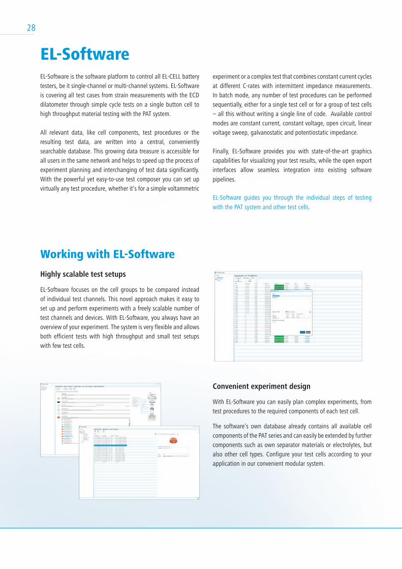
EL-SoftwareEL-Software is the software platform to control all EL-CELL battery testers, be it single-channel or multi-channel systems. EL-Software is covering all test cases from strain measurements with the ECD dilatometer through simple cycle tests on a single button cell to high throughput material testing with the PAT system.
All relevant data, like cell components, test procedures or the resulting test data, are written into a central, conveniently searchable database. This growing data treasure is accessible for all users in the same network and helps to speed up the process of experiment planning and interchanging of test data significantly. With the powerful yet easy-to-use test composer you can set up virtually any test procedure, whether it‘s for a simple voltammetric
experiment or a complex test that combines constant current cycles at different C-rates with intermittent impedance measurements. In batch mode, any number of test procedures can be performed sequentially, either for a single test cell or for a group of test cells – all this without writing a single line of code. Available control modes are constant current, constant voltage, open circuit, linear voltage sweep, galvanostatic and potentiostatic impedance.
Finally, EL-Software provides you with state-of-the-art graphics capabilities for visualizing your test results, while the open export interfaces allow seamless integration into existing software
pipelines.
EL-Software guides you through the individual steps of testing
with the PAT system and other test cells.
Highly scalable test setups
EL-Software focuses on the cell groups to be compared instead of individual test channels. This novel approach makes it easy to set up and perform experiments with a freely scalable number of test channels and devices. With EL-Software, you always have an overview of your experiment. The system is very flexible and allows both efficient tests with high throughput and small test setups with few test cells.
Working with EL-Software
Convenient experiment design
With EL-Software you can easily plan complex experiments, from test procedures to the required components of each test cell.
The software’s own database already contains all available cell components of the PAT series and can easily be extended by further components such as own separator materials or electrolytes, but also other cell types. Configure your test cells according to your application in our convenient modular system.
28
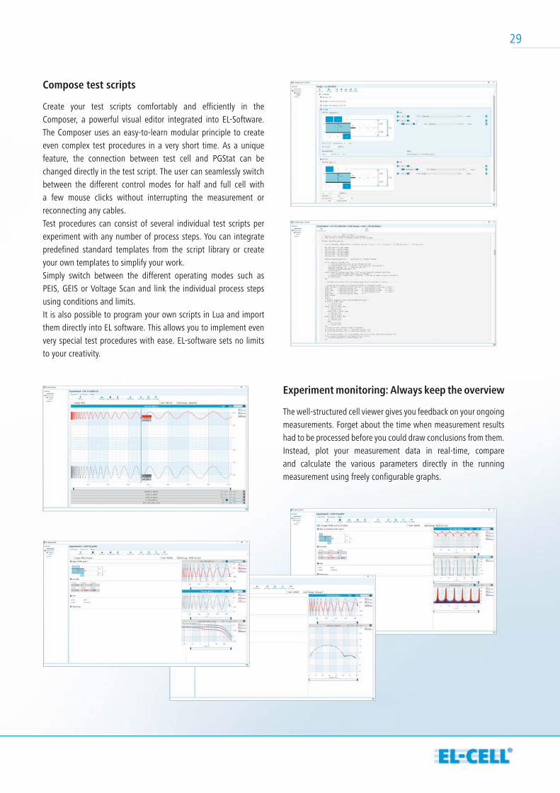
Compose test scripts
Create your test scripts comfortably and efficiently in the Composer, a powerful visual editor integrated into EL-Software. The Composer uses an easy-to-learn modular principle to create even complex test procedures in a very short time. As a unique feature, the connection between test cell and PGStat can be changed directly in the test script. The user can seamlessly switch between the different control modes for half and full cell with a few mouse clicks without interrupting the measurement or reconnecting any cables.Test procedures can consist of several individual test scripts per experiment with any number of process steps. You can integrate predefined standard templates from the script library or create your own templates to simplify your work.Simply switch between the different operating modes such as PEIS, GEIS or Voltage Scan and link the individual process steps using conditions and limits.It is also possible to program your own scripts in Lua and import them directly into EL software. This allows you to implement even very special test procedures with ease. EL-software sets no limits to your creativity.
Experiment monitoring: Always keep the overview
The well-structured cell viewer gives you feedback on your ongoing measurements. Forget about the time when measurement results had to be processed before you could draw conclusions from them. Instead, plot your measurement data in real-time, compare and calculate the various parameters directly in the running measurement using freely configurable graphs.
29
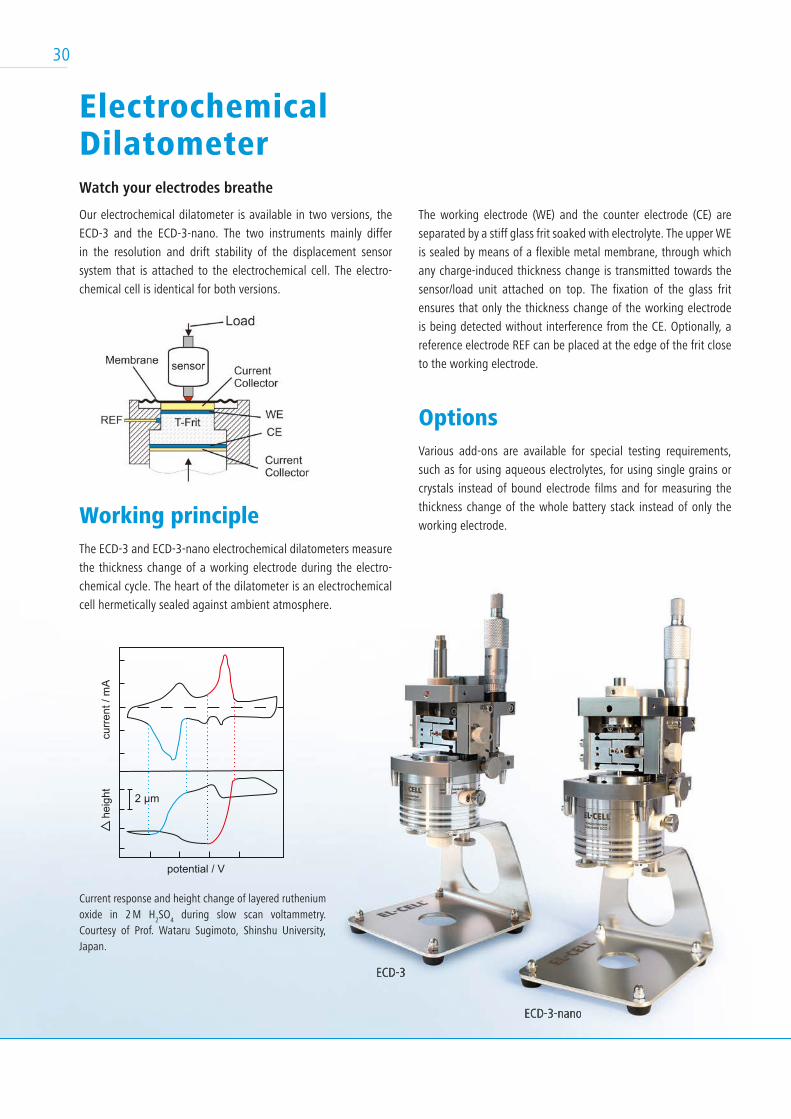
Electrochemical DilatometerWatch your electrodes breathe
Our electrochemical dilatometer is available in two versions, the
ECD-3 and the ECD-3-nano. The two instruments mainly differ
in the resolution and drift stability of the displacement sensor
system that is attached to the electrochemical cell. The electro-
chemical cell is identical for both versions.
Working principle The ECD-3 and ECD-3-nano electrochemical dilatometers measure
the thickness change of a working electrode during the electro-
chemical cycle. The heart of the dilatometer is an electrochemical
cell hermetically sealed against ambient atmosphere.
The working electrode (WE) and the counter electrode (CE) are
separated by a stiff glass frit soaked with electrolyte. The upper WE
is sealed by means of a flexible metal membrane, through which
any charge-induced thickness change is transmitted towards the
sensor/load unit attached on top. The fixation of the glass frit
ensures that only the thickness change of the working electrode
is being detected without interference from the CE. Optionally, a
reference electrode REF can be placed at the edge of the frit close
to the working electrode.
OptionsVarious add-ons are available for special testing requirements,
such as for using aqueous electrolytes, for using single grains or
crystals instead of bound electrode films and for measuring the
thickness change of the whole battery stack instead of only the
working electrode.
ECD-3-nano
ECD-3
Current response and height change of layered ruthenium oxide in 2 M H
2SO
4 during slow scan voltammetry.
Courtesy of Prof. Wataru Sugimoto, Shinshu University, Japan.
curr
ent /
mA
potential / V
heig
ht 2 µm
30
ECD-3 ECD-3 nano
Displacement sensor system LVDT capacitive
Displacement range 500 µm 250 µm
Displacement resolution ≤ 50 nm ≤ 5 nm
Signal drift (sample-free) ≤ 100 nm / hour ≤ 20 nm / hour
Test specimen Electrode films, optional single crystals / grains
Diameter ≤ 10 mm, thickness ≤ 1 mm
Load on test specimen approx. 1 N
Chemical compatibility Aprotic organic electrolytes; optional aqueous electrolytes
Cell electrolyte volume approx. 0.5 ml
Technical Specifi cations
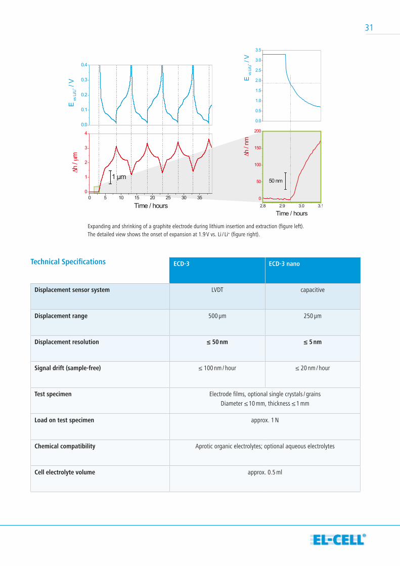
Expanding and shrinking of a graphite electrode during lithium insertion and extraction (figure left). The detailed view shows the onset of expansion at 1.9 V vs. Li / Li+ (figure right).
31
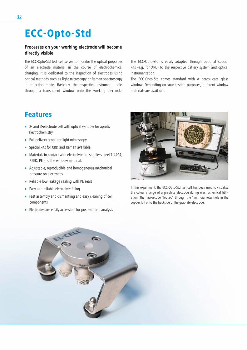
ECC-Opto-StdProcesses on your working electrode will become directly visible
The ECC-Opto-Std test cell serves to monitor the optical properties
of an electrode material in the course of electrochemical
charging. It is dedicated to the inspection of electrodes using
optical methods such as light microscopy or Raman spectroscopy
in reflection mode. Basically, the respective instrument looks
through a transparent window onto the working electrode.
Features
2- and 3-electrode cell with optical window for aprotic
electrochemistry
Full delivery scope for light microscopy
Special kits for XRD and Raman available
Materials in contact with electrolyte are stainless steel 1.4404,
PEEK, PE and the window material.
Adjustable, reproducible and homogeneous mechanical
pressure on electrodes
Reliable low-leakage sealing with PE seals
Easy and reliable electrolyte filling
Fast assembly and dismantling and easy cleaning of cell
components
Electrodes are easily accessible for post-mortem analysis
The ECC-Opto-Std is easily adapted through optional special
kits (e.g. for XRD) to the respective battery system and optical
instrumentation.
The ECC-Opto-Std comes standard with a borosilicate glass
window. Depending on your testing purposes, different window
materials are available.
In this experiment, the ECC-Opto-Std test cell has been used to visualize the colour change of a graphite electrode during electrochemical lithi-ation. The microscope “looked” through the 1 mm diameter hole in the copper foil onto the backside of the graphite electrode.
3232
3333
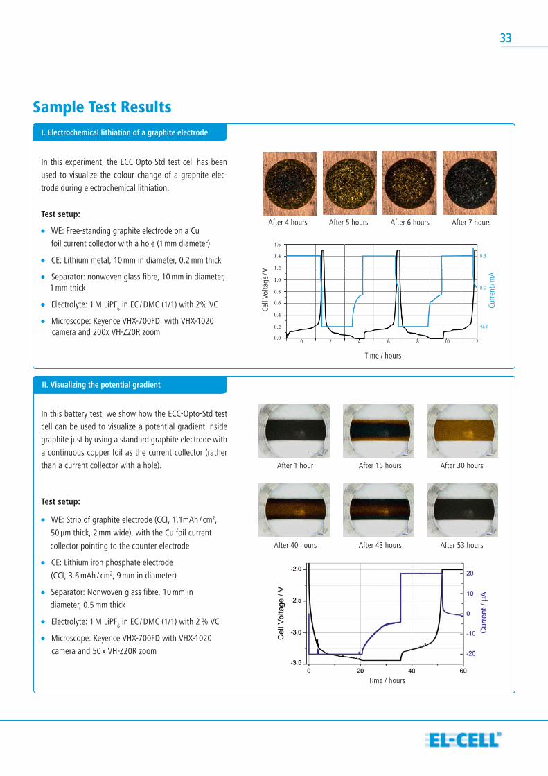
Sample Test Results
In this experiment, the ECC-Opto-Std test cell has been
used to visualize the colour change of a graphite elec-
trode during electrochemical lithiation.
Test setup:
WE: Free-standing graphite electrode on a Cu
foil current collector with a hole (1 mm diameter)
CE: Lithium metal, 10 mm in diameter, 0.2 mm thick
Separator: nonwoven glass fibre, 10 mm in diameter, 1 mm thick
Electrolyte: 1 M LiPF6 in EC / DMC (1/1) with 2% VC
Microscope: Keyence VHX-700FD with VHX-1020 camera and 200x VH-Z20R zoom
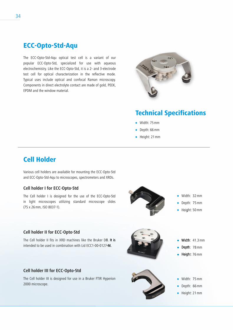
In this battery test, we show how the ECC-Opto-Std test
cell can be used to visualize a potential gradient inside
graphite just by using a standard graphite electrode with
a continuous copper foil as the current collector (rather
than a current collector with a hole).
Test setup:
WE: Strip of graphite electrode (CCI, 1.1mAh / cm2,
50 µm thick, 2 mm wide), with the Cu foil current
collector pointing to the counter electrode
CE: Lithium iron phosphate electrode
(CCI, 3.6 mAh / cm2, 9 mm in diameter)
Separator: Nonwoven glass fibre, 10 mm in
diameter, 0.5 mm thick
Electrolyte: 1 M LiPF6 in EC / DMC (1/1) with 2 % VC
Microscope: Keyence VHX-700FD with VHX-1020
camera and 50 x VH-Z20R zoom
After 4 hours
1.6
1.4
1.2
1.0
0.8
0.6
0.4
0.2
0.0
0.3
0.0
-0.3
0 2 4 6 8 10 12
Time / hours
Time / hours
Cell
Volta
ge / V
Curre
nt / m
A
After 5 hours After 6 hours After 7 hours
I. Electrochemical lithiation of a graphite electrode
II. Visualizing the potential gradient
After 1 hour
After 40 hours
After 15 hours
After 43 hours
After 30 hours
After 53 hours
33
34
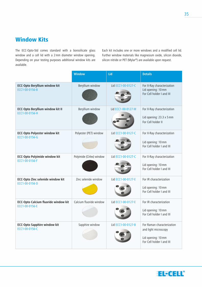
ECC-Opto-Std-Aqu
The ECC-Opto-Std-Aqu optical test cell is a variant of our
popular ECC-Opto-Std, specialized for use with aqueous
electrochemistry. Like the ECC-Opto-Std, it is a 2- and 3-electrode
test cell for optical characterization in the reflective mode.
Typical uses include optical and confocal Raman microscopy.
Components in direct electrolyte contact are made of gold, PEEK,
EPDM and the window material.
Technical Specifications Width: 75 mm
Depth: 66 mm
Height: 21 mm
Width: 32 mm
Depth: 75 mm
Height: 50 mm
Width: 41.3 mm
Depth: 78 mm
Height: 76 mm
Width: 75 mm
Depth: 66 mm
Height: 21 mm
Cell Holder
Various cell holders are available for mounting the ECC-Opto-Std
and ECC-Opto-Std-Aqu to microscopes, spectrometers and XRDs.
Cell holder I for ECC-Opto-Std
The Cell holder I is designed for the use of the ECC-Opto-Std
in light microscopes utilizing standard microscope slides
(75 x 26 mm, ISO 8037-1).
Cell holder II for ECC-Opto-Std
The Cell holder II fits in XRD machines like the Bruker D8. It is
intended to be used in combination with Lid ECC1-00-0127-M.
Cell holder III for ECC-Opto-Std
The Cell holder III is designed for use in a Bruker FTIR Hyperion
2000 microscope.
Height: 50 mm
Width: 41.3 mm
Depth: 78 mm
Height: 76 mm
The Cell holder II fits in XRD machines like the Bruker D8. It is
intended to be used in combination with Lid ECC1-00-0127-M.
35
Window Kits
Cell holder
The ECC-Opto-Std comes standard with a borosilicate glass
window and a cell lid with a 2 mm diameter window opening.
Depending on your testing purposes additional window kits are
available.
Each kit includes one or more windows and a modified cell lid.
Further window materials like magnesium oxide, silicon dioxide,
silicon nitride or PET (Mylar®) are available upon request.
Window Lid Details
ECC-Opto Beryllium window kitECC1-00-0156-B
Beryllium window Lid ECC1-00-0127-C For X-Ray characterizationLid opening: 10 mmFor Cell holder I and III
ECC-Opto Beryllium window kit II ECC1-00-0156-H
Beryllium window Lid ECC1-00-0127-M For X-Ray characterization
Lid opening: 23.3 x 5 mm
For Cell holder II
ECC-Opto Polyester window kit ECC1-00-0156-G
Polyester (PET) window Lid ECC1-00-0127-C For X-Ray characterization
Lid opening: 10 mmFor Cell holder I and III
ECC-Opto Polyimide window kit ECC1-00-0156-F
Polyimide (Cirlex) window Lid ECC1-00-0127-C For X-Ray characterization
Lid opening: 10 mmFor Cell holder I and III
ECC-Opto Zinc selenide window kit ECC1-00-0156-D
Zinc selenide window Lid ECC1-00-0127-E For IR characterization
Lid opening: 10 mmFor Cell holder I and III
ECC-Opto Calcium fl uoride window kit ECC1-00-0156-E
Calcium fluoride window Lid ECC1-00-0127-E For IR characterization
Lid opening: 10 mmFor Cell holder I and III
ECC-Opto Sapphire window kit ECC1-00-0156-C
Sapphire window Lid ECC1-00-0127-B For Raman characterization
and light microscopy
Lid opening: 10 mmFor Cell holder I and III
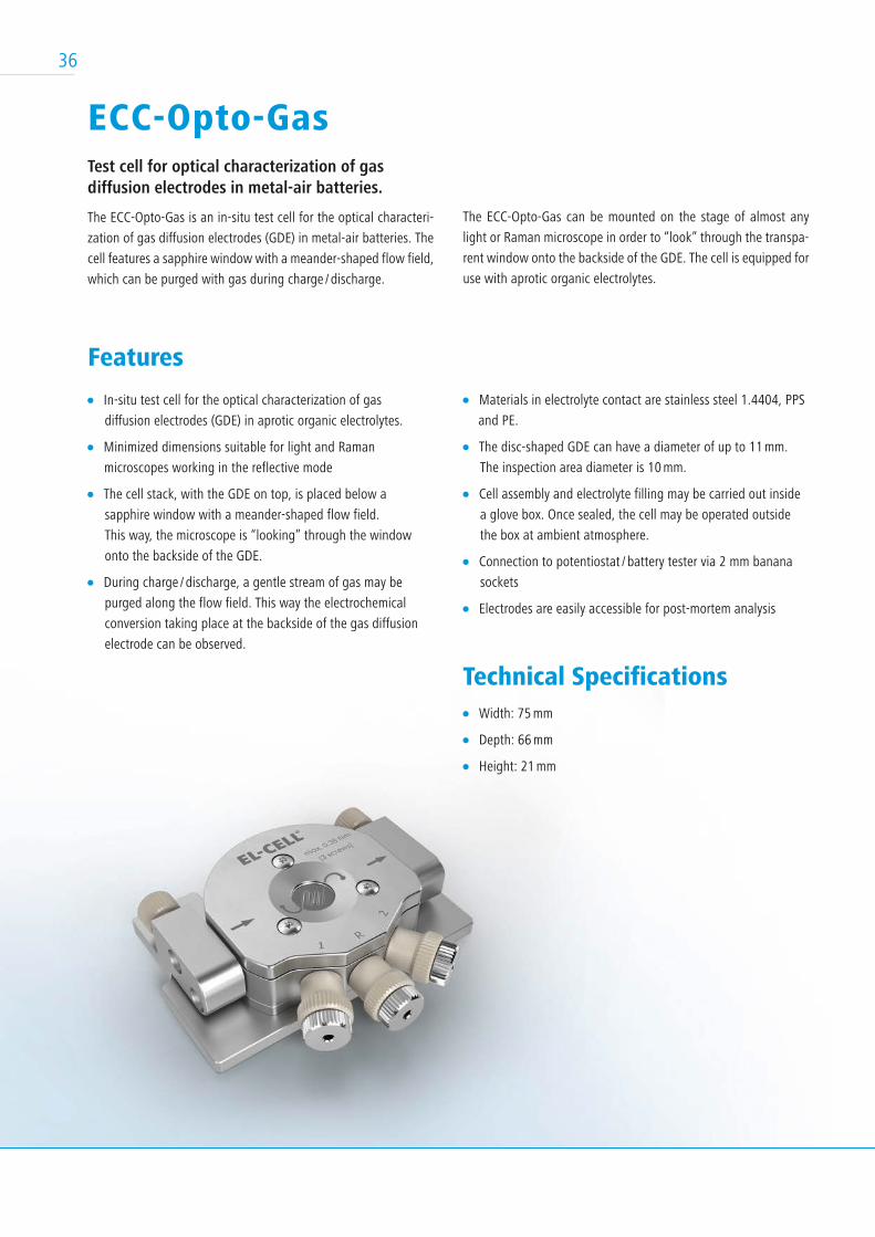
ECC-Opto-GasTest cell for optical characterization of gas diffusion electrodes in metal-air batteries.
The ECC-Opto-Gas is an in-situ test cell for the optical characteri-
zation of gas diffusion electrodes (GDE) in metal-air batteries. The
cell features a sapphire window with a meander-shaped flow field,
which can be purged with gas during charge / discharge.
Features
In-situ test cell for the optical characterization of gas
diffusion electrodes (GDE) in aprotic organic electrolytes.
Minimized dimensions suitable for light and Raman
microscopes working in the reflective mode
The cell stack, with the GDE on top, is placed below a
sapphire window with a meander-shaped flow field.
This way, the microscope is “looking” through the window
onto the backside of the GDE.
During charge / discharge, a gentle stream of gas may be
purged along the flow field. This way the electrochemical
conversion taking place at the backside of the gas diffusion
electrode can be observed.
The ECC-Opto-Gas can be mounted on the stage of almost any
light or Raman microscope in order to “look” through the transpa-
rent window onto the backside of the GDE. The cell is equipped for
use with aprotic organic electrolytes.
Materials in electrolyte contact are stainless steel 1.4404, PPS
and PE.
The disc-shaped GDE can have a diameter of up to 11 mm.
The inspection area diameter is 10 mm.
Cell assembly and electrolyte filling may be carried out inside
a glove box. Once sealed, the cell may be operated outside
the box at ambient atmosphere.
Connection to potentiostat / battery tester via 2 mm banana
sockets
Electrodes are easily accessible for post-mortem analysis
Technical Specifications Width: 75 mm
Depth: 66 mm
Height: 21 mm
36
37
Accessories & ToolsEL-CELL® offers useful tools and accessories for enhancing the work experience with our test cells and to
ease your life as a battery researcher.
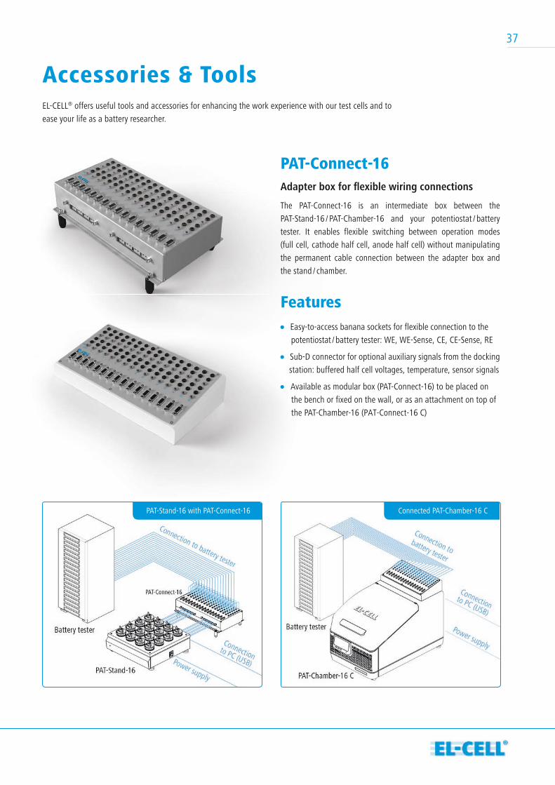
PAT-Connect-16Adapter box for fl exible wiring connections
The PAT-Connect-16 is an intermediate box between the
PAT-Stand-16 / PAT-Chamber-16 and your potentiostat / battery
tester. It enables flexible switching between operation modes
(full cell, cathode half cell, anode half cell) without manipulating
the permanent cable connection between the adapter box and
the stand / chamber.
Features Easy-to-access banana sockets for flexible connection to the
potentiostat / battery tester: WE, WE-Sense, CE, CE-Sense, RE
Sub-D connector for optional auxiliary signals from the docking
station: buffered half cell voltages, temperature, sensor signals
Available as modular box (PAT-Connect-16) to be placed on
the bench or fixed on the wall, or as an attachment on top of
the PAT-Chamber-16 (PAT-Connect-16 C)
PAT-Stand-16 with PAT-Connect-16 Connected PAT-Chamber-16 C
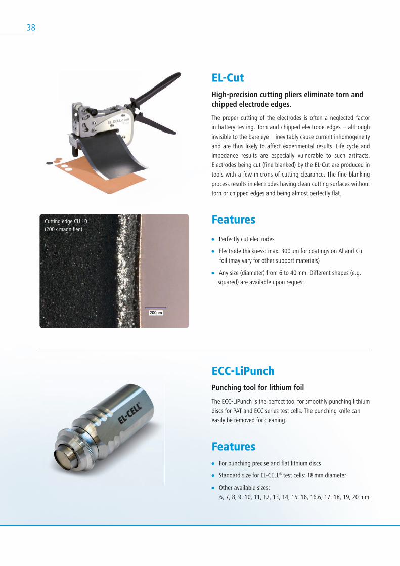
EL-CutHigh-precision cutting pliers eliminate torn and chipped electrode edges.
The proper cutting of the electrodes is often a neglected factor
in battery testing. Torn and chipped electrode edges – although
invisible to the bare eye – inevitably cause current inhomogeneity
and are thus likely to affect experimental results. Life cycle and
impedance results are especially vulnerable to such artifacts.
Electrodes being cut (fine blanked) by the EL-Cut are produced in
tools with a few microns of cutting clearance. The fine blanking
process results in electrodes having clean cutting surfaces without
torn or chipped edges and being almost perfectly flat.
Features
Perfectly cut electrodes
Electrode thickness: max. 300 µm for coatings on Al and Cu
foil (may vary for other support materials)
Any size (diameter) from 6 to 40 mm. Different shapes (e.g.
squared) are available upon request.
38
Cutting edge CU 10 (200 x magnified)
Cutting edge CU 10 (200 x magnified)
Cutting edge of AL 20 (200 x magnified)
ECC-LiPunchPunching tool for lithium foil
The ECC-LiPunch is the perfect tool for smoothly punching lithium
discs for PAT and ECC series test cells. The punching knife can
easily be removed for cleaning.
Features For punching precise and flat lithium discs
Standard size for EL-CELL® test cells: 18 mm diameter
Other available sizes:
6, 7, 8, 9, 10, 11, 12, 13, 14, 15, 16, 16.6, 17, 18, 19, 20 mm
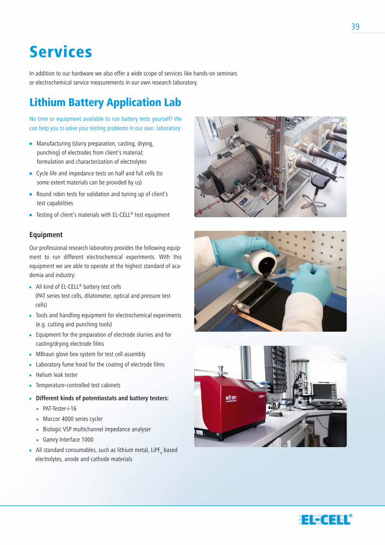
ServicesIn addition to our hardware we also offer a wide scope of services like hands-on seminars
or electrochemical service measurements in our own research laboratory.
Lithium Battery Application LabNo time or equipment available to run battery tests yourself? We
can help you to solve your testing problems in our own laboratory:
Manufacturing (slurry preparation, casting, drying,
punching) of electrodes from client‘s material;
formulation and characterization of electrolytes
Cycle life and impedance tests on half and full cells (to
some extent materials can be provided by us)
Round robin tests for validation and tuning up of client’s
test capabilities
Testing of client‘s materials with EL-CELL® test equipment
Equipment
Our professional research laboratory provides the following equip-
ment to run different electrochemical experiments. With this
equipment we are able to operate at the highest standard of aca-
demia and industry:
All kind of EL-CELL® battery test cells
(PAT series test cells, dilatometer, optical and pressure test
cells)
Tools and handling equipment for electrochemical experiments
(e.g. cutting and punching tools)
Equipment for the preparation of electrode slurries and for
casting/drying electrode films
MBraun glove box system for test cell assembly
Laboratory fume hood for the coating of electrode films
Helium leak tester
Temperature-controlled test cabinets
Different kinds of potentiostats and battery testers:
PAT-Tester-i-16
Maccor 4000 series cycler
Biologic VSP multichannel impedance analyser
Gamry Interface 1000
All standard consumables, such as lithium metal, LiPF6 based
electrolytes, anode and cathode materials
39
40
Hands-on SeminarsIn our seminars, researchers can learn about the latest devices and applications while working efficiently with our products.
Covered topics:
Li-ion battery introduction: Working principles, terminology,
materials used, related technologies (Li-metal batteries,
Li-ion capacitors, supercapacitors, dual intercalation
batteries)
Safety and corrosion issues in the Li-ion research laboratory
Electrode generation from powder to sheet
Pros and cons of different test cells (coin, pouch cells,
Swagelok®,Hohsen, PAT-Cell)
Building 2- and 3-electrode PAT-Cells
Testing with PAT-Cells and PAT-Tester-i-16:
Lifetime and CC-CV cycle tests
Impedance measurements
Cyclic voltammetry
Electrochemical in-situ / operando techniques with
ECC-Opto-Std: Visualizing the gradients of electrode
potential and lithium concentration
PAT-Cell-Press: Quantifying the gassing during battery
formation
ECD-3-nano: Measuring electrode dilation during charge and
discharge
Facts:
Duration: two days (8 hours per day)
Location: Tempowerkring 8 - 21079 Hamburg, Germany
Pricing: regular registration: 1,300 Euro (1,200 Euro*)
PhD-students**: 650 Euro (600 Euro*)
See website www.el-cell.com for next dates.
* Early bird (4 weeks before)
** confirmation required
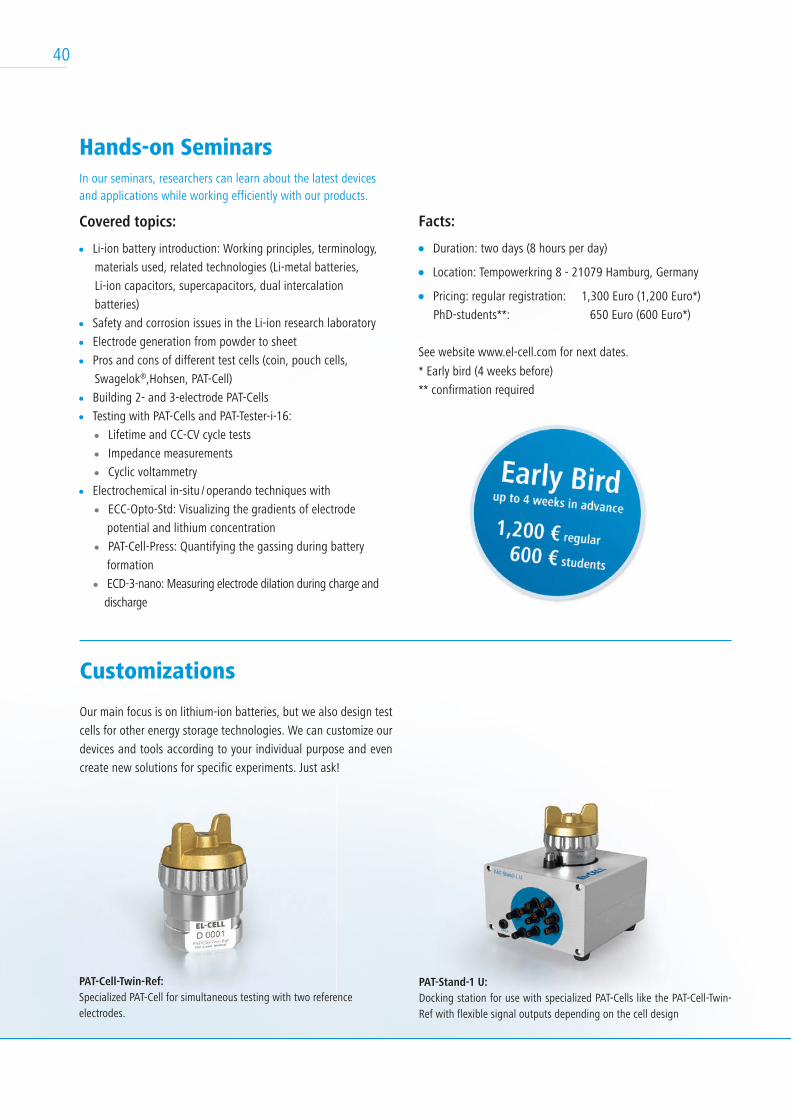
Customizations
Our main focus is on lithium-ion batteries, but we also design test
cells for other energy storage technologies. We can customize our
devices and tools according to your individual purpose and even
create new solutions for specific experiments. Just ask!
PAT-Cell-Twin-Ref:Specialized PAT-Cell for simultaneous testing with two reference electrodes.
PAT-Stand-1 U:Docking station for use with specialized PAT-Cells like the PAT-Cell-Twin-Ref with flexible signal outputs depending on the cell design
40
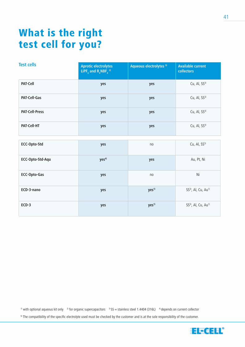
Aprotic electrolytesLiPF6 and R4NBF4
2)
Aqueous electrolytes 5) Available current collectors
PAT-Cell yes yes Cu, Al, SS3)
PAT-Cell-Gas yes yes Cu, Al, SS3)
PAT-Cell-Press yes yes Cu, Al, SS3)
PAT-Cell-HT yes yes Cu, Al, SS3)
Test cells
What is the right test cell for you?
ECC-Opto-Std yes no Cu, Al, SS3)
ECC-Opto-Std-Aqu yes4) yes Au, Pt, Ni
ECC-Opto-Gas yes no Ni
ECD-3-nano yes yes1) SS3), Al, Cu, Au1)
ECD-3 yes yes1) SS3), Al, Cu, Au1)
1) with optional aqueous kit only 2) for organic supercapacitors 3) SS = stainless steel 1.4404 (316L) 4) depends on current collector
5) The compatibility of the specific electrolyte used must be checked by the customer and is at the sole responsibility of the customer.
41
42
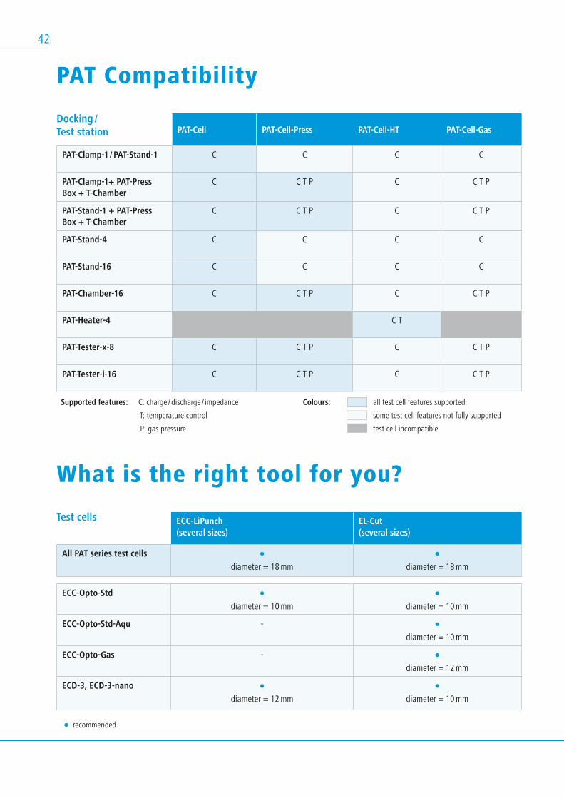
PAT-Cell PAT-Cell-Press PAT-Cell-HT PAT-Cell-Gas
PAT-Clamp-1 / PAT-Stand-1 C C C C
PAT-Clamp-1+ PAT-Press Box + T-Chamber
C C T P C C T P
PAT-Stand-1 + PAT-Press Box + T-Chamber
C C T P C C T P
PAT-Stand-4 C C C C
PAT-Stand-16 C C C C
PAT-Chamber-16 C C T P C C T P
PAT-Heater-4 C T
PAT-Tester-x-8 C C T P C C T P
PAT-Tester-i-16 C C T P C C T P
Docking / Test station
ECC-LiPunch(several sizes)
EL-Cut (several sizes)
All PAT series test cellsdiameter = 18 mm diameter = 18 mm
Test cells
PAT Compatibility
What is the right tool for you?
ECC-Opto-Stddiameter = 10 mm diameter = 10 mm
ECC-Opto-Std-Aqu -
diameter = 10 mm
ECC-Opto-Gas -
diameter = 12 mm
ECD-3, ECD-3-nanodiameter = 12 mm diameter = 10 mm
recommended
Supported features: C: charge / discharge / impedance
T: temperature control
P: gas pressure
Colours: all test cell features supported
some test cell features not fully supported
test cell incompatible
some test cell features not fully supported some test cell features not fully supported

EL-Cell GmbH
Tempowerkring 8
21079 Hamburg
Germany
3V 4V 5V
phone: +49 40 79012-734
fax: +49 40 79012-736
email: [email protected]
web: www.el-cell.com
EL-CELL® delivers worldwide directly and through its
japanese distributor.
For further information please visit our website www.el-cell.com or contact us directly!
Christoph GrassauSales Manager
Susana Moreira Sales Manager
EL-Cell GmbHHamburg, Germany
EL-CELL® GmbHTempowerkring 821079 HamburgGermany