Embed Size (px)
Citation preview
The condensing unit must only be used for its designed purpose(s) and within its scope of application.
Under all circumstances, the EN378 (or other applicable local safety regulation) requirements must be fulfilled.
The condensing unit is delivered under nitro-gen gas pressure (1 bar) and hence it cannot be connected as it is; refer to the «installation» section for further details.
The condensing unit must be handled with cau-tion in the vertical position (maximum offset from the vertical : 15°)
FRCC.EI.019.A1.02 © Danfoss Commercial Compressors 11/111
ABC
D
EFG
H
Designation OP-MPHM007NFP00G Code Number 114X4101Refrigerant (1) R404A R507A R407C (2)R134a
Voltage (V) 220V-240VFrequency (Hz) 50HzNumber of Phases 1LRA (A) 41MCC (A) 12Application MBPProtection IP54Max Working Pressure (bar) HP(1) 28 HP(2) 23 LP (1) 7 LP(2) 5
Serial No. 123456BS0310Barcode Serial No:
Made in India
I
J
MLK
N OP
INSTRUCTIONSOPTYMA PLUS CONDENSING UNITS
OP-LPHM, OP-MPHM, OP-MPUM, OP-MPGM
Installation and servicing of the condensing units by qualified
personnel only. Follow these instructions and sound refrigeration engineering practice relating to installation, commissioning, maintenance and service.
A: Model
B: Code number
C: Refrigerant
D: Supply voltage, Locked Rotor Ampere, Maxi-
mum Current Consumption
E: Application
F: Protection
G: Housing Service Pressure
H: Serial Number and bar code
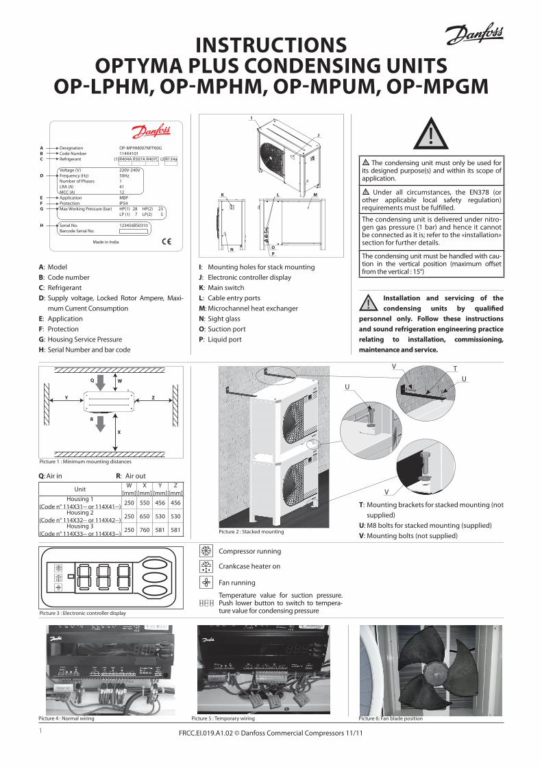
I: Mounting holes for stack mounting
J: Electronic controller display
K: Main switch
L: Cable entry ports
M: Microchannel heat exchanger
N: Sight glass
O: Suction port
P: Liquid port
Compressor running
Crankcase heater on
Fan running
Temperature value for suction pressure. Push lower button to switch to tempera-ture value for condensing pressure Picture 3 : Electronic controller display
WQ
R
X
ZY
Q: Air in R: Air out
UnitW
[mm]X
[mm]Y
[mm]Z
[mm]Housing 1
(Code n° 114X31-- or 114X41--)250 550 456 456
Housing 2 (Code n° 114X32-- or 114X42--)
250 650 530 530
Housing 3 (Code n° 114X33-- or 114X43--)
250 760 581 581
Picture 1 : Minimum mounting distances
Picture 4 : Normal wiring Picture 5 : Temporary wiring Picture 6: Fan blade position
T: Mounting brackets for stacked mounting (not
supplied)
U: M8 bolts for stacked mounting (supplied)
V: Mounting bolts (not supplied)
TU
U
V
V
Picture 2 : Stacked mounting

2 FRCC.EI.019.A1.02 © Danfoss Commercial Compressors 11/11
Instructions
1 – Introduction
These instructions pertain to Optyma Plus
condensing units OP-LPHM, OP-MPHM, OP-
MPUM and OP-MPGM used for refrigeration
systems. They provide necessary information re-
garding safety and proper usage of this product.
The condensing unit includes following:
• Microchannel heat exchanger
• Reciprocating or scroll compressor
• Receiver with stop valve
• Ball valves
• Sight glass
• High & low pressure switches
• Filter drier
• Electronic controller
• Main circuit breaker (Main switch with over-
load protection)
• Fan and compressor capacitors
• Compressor contactor
• Robust weather proof housing
2 – Handling and storage
• It is recommended not to open the packaging
before the unit is at the final place for installa-
tion.
• Handle the unit with care. The packaging al-
lows for the use of a forklift or pallet jack. Use
appropriate and safe lifting equipment..
• Store and transport the unit in an upright po-
sition.
• Store the unit between -35°C and 50°C.
• Don’t expose the packaging to rain or corro-
sive atmosphere.
• After unpacking, check that the unit is com-
plete and undamaged.
3 – Installation precautions
Never place the unit in a flammable atmos-
phere
Place the unit in such a way that it is not bloc-
king or hindering walking areas, doors, windows
or similar.
• Ensure adequate space around the unit for air
circulation and to open doors. Refer to picture
1 for minimal values of distance to walls.
• Avoid installing the unit in locations which are
daily exposed to direct sunshine for longer
periods.
• Avoid installing the unit in aggressive and
dusty environments.
• Ensure a foundation with horizontal surface
(less than 3° slope), strong and stable enough
to carry the entire unit weight and to elimi-
nate vibrations and interference.
• The unit ambient temperature may not ex-
ceed 50°C during off-cycle.
• Ensure that the power supply corresponds to
the unit characteristics (see nameplate).
• When installing units for HFC refrigerants,
use equipment specifically reserved for HFC
refrigerants which was never used for CFC or
HCFC refrigerants.
• Use clean and dehydrated refrigeration-grade
copper tubes and silver alloy brazing material.
• Use clean and dehydrated system components.
• The suction piping connected to the com-
pressor must be flexible in 3 dimensions to
dampen vibrations. Furthermore piping has
to be done in such a way that oil return for the
compressor is ensured and the risk of liquid
slug over in compressor is eliminated.
4 – Installation
• The installation in which the condensing unit is
installed must comply to EEC Pressure directive
(PED) nr. 97/23/EC. The condensing unit itself is
not a ”unit” in the scope this directive.
• It is recommended to install the unit on rubber
grommets or vibration dampers (not supplied).
• It is possible to stack units on top of each
other.
UnitMaximum stacking
Housing 1 (Code no. 114X31-- or 114X41--)
3
Housing 2 (Code no. 114X32-- or 114X42--)
2
Housing 3 (Code no. 114X33-- or 114X43--)
2
• When stacking, the topmost unit must be se-
cured to the wall, as shown in picture 2.
• Slowly release the nitrogen holding charge
through the schrader port.
• Connect the unit to the system as soon as pos-
sible to avoid oil contamination from ambient
moisture.
• Avoid material entering into the system while
cutting tubes. Never drill holes where burrs
cannot be removed.
• Braze with great care using state-of-the-art
technique and vent piping with nitrogen gas
flow.
• Connect the required safety and control de-
vices. When the schrader port is used for this,
remove the internal valve.
• It is recommended to insulate the suction
pipe up to the compressor inlet with 19 mm
thick insulation.
5 – Leak detection
Never pressurize the circuit with oxygen or
dry air. This could cause fire or explosion.
• Do not use dye for leak detection
• Perform a leak detection test on the complete
system
• The maximum test pressure is 32 bar.
• When a leak is discovered, repair the leak and
repeat the leak detection.
6 – Vacuum dehydration
• Never use the compressor to evacuate the sys-
tem.
• Connect a vacuum pump to both the LP & HP
sides.
• Pull down the system under a vacuum of 500
µm Hg (0.67 mbar) absolute.
• Do not use a megohmmeter nor apply power
to the compressor while it is under vacuum as
this may cause internal damage.
7 – Electrical connections
• Switch off and isolate the main power supply.
• Ensure that power supply can not be switched
on during installation.
• All electrical components must be selected as
per local standards and unit requirements.
• Refer to wiring diagram for electrical connec-
tions details.
• Ensure that the power supply corresponds to
the unit characteristics and that the power
supply is stable (nominal voltage ±10% and
nominal frequency ±2,5 Hz)
• Dimension the power supply cables accor-
ding to unit data for voltage and current.
• Protect the power supply and ensure correct
earthing.
• Make the power supply according to local
standards and legal requirements
• The unit is equipped with an electronic control-
ler. Refer to Manual RS8GD302 for details.
• The unit is equipped with a main switch with
overload protection. The overload protec-
tion is factory preset but it is recommended
to check the value before taking the unit in
operation. The value for the overload protec-
tion can be found in the wiring diagram in the
front door of the unit.
• The unit is equipped with high and low pres-
sure switches, which directly cut the power
supply to the compressor in case of activation.
Parameters for high and low pressure cut outs
are preset in the controller, adapted to the
compressor installed in the unit.
For units with a 3-phase scroll compressor (OP-
MPUMxxxxxxxxE), correct phase sequence for
compressor rotation direction shall be observed.
• Determine the phase sequence by using a
phase meter in order to establish the phase
orders of line phases L1, L2 and L3.
• Connect line phases L1, L2 and L3 to main
switch terminals T1, T2 and T3 respectively.
8 – Filling the system
• Never start the compressor under vacuum.
Keep the compressor switched off.
• Use only the refrigerant for which the unit is
designed for.
• Fill the refrigerant in liquid phase into the
condenser or liquid receiver. Ensure a slow
charging of the system to 4 – 5 bar for R404A
and approx. 2 bar for R134a.
• The remaining charge is done until the instal-
lation has reached a level of stable nominal
condition during operation.

3FRCC.EI.019.A1.02 © Danfoss Commercial Compressors 11/11
Instructions
• Never leave the filling cylinder connected to
the circuit.
9 – Setting the electronic controller
• The unit is equipped with an electronic control-
ler which is factory programmed with parame-
ters for use with the actual unit. Refer to Ma-
nual RS8GD302 for details.
• By default, the electronic controller display
shows the temperature value for the suction
pressure in °C. To show the temperature value
for the condensing pressure, push the lower
button (picture 3).
The electronic controller is factory preset for
operation with refrigerant R404A. If another re-
frigerant is used, the refrigerant setting must be
changed;
• Push the upper button for a couple of seconds.
The column with parameter codes appears.
• Push the upper and lower buttons to find para-
meter code o30.
• Push the middle button until the value for this
parameter is shown.
• Push the upper and lower buttons to select the
new value: 2 = R22, 3 = R134a, 13 = User defi-
ned, 17 = R507, 19 = R404A, 20 = R407C.
• Push the middle button to confirm the selected
value.
10 – Verification before commissioning
Use safety devices such as safety pressure
switch and mechanical relief valve in com-
pliance with both generally and locally appli-
cable regulations and safety standards. Ensure
that they are operational and properly set.
Check that the settings of high-pressure
switches and relief valves don’t exceed the maxi-
mum service pressure of any system component.
• Verify that all electrical connections are pro-
perly fastened and in compliance with local
regulations.
• When a crankcase heater is required, it must
be energized at least 12 hours before initial
start-up and start-up after prolonged shu-
tdown for belt type crankcase heaters.
• The unit is equipped with a main switch with
overload protection. Overload protection is
preset from factory, but it is recommended to
check the value before taking the unit in ope-
ration. The overload protection value can be
found in the wiring diagram in the unit front
door.
11 – Start-up
• Never start the unit when no refrigerant is
charged.
• All service valves must be in the open position.
• Check compliance between unit and power
supply.
• Check that the crankcase heater is working.
• Check that the fan can rotate freely.
• Check that the protection sheet has been re-
moved from the backside of condenser.
• Balance the HP/LP pressure.
• Energize the unit. It must start promptly. If
the compressor does not start, check wiring
conformity and voltage on terminals.
• Eventual reverse rotation of a 3-phase com-
pressor can be detected by following pheno-
mena; the compressor doesn’t build up pres-
sure, it has abnormally high sound level and
abnormally low power consumption. In such
case, shut down the unit immediately and
connect the phases to their proper terminals.
• If the rotation direction is correct the low pres-
sure indication on the controller (or low pres-
sure gauge) shall show a declining pressure
and the high pressure indication (or high pres-
sure gauge) shall show an increasing pressure.
12 – Check with running unit
• Check the fan rotation direction. Air must flow
from the condenser towards the fan.
• Check current draw and voltage.
• Check suction superheat to reduce risk of
slugging.
• When a sight glass is provided observe the oil
level at start and during operation to confirm
that the oil level remains visible.
• Respect the operating limits.
• Check all tubes for abnormal vibration. Move-
ments in excess of 1.5 mm require corrective
measures such as tube brackets.
• When needed, additional refrigerant in liquid
phase may be added in the low-pressure side as
far as possible from the compressor. The com-
pressor must be operating during this process.
• Do not overcharge the system.
• Never release refrigerant to atmosphere.
• Before leaving the installation site, carry out
a general installation inspection regarding
cleanliness, noise and leak detection.
• Record type and amount of refrigerant charge
as well as operating conditions as a reference
for future inspections.
13 – Emergency running without controller
In case of controller failure, the condensing unit
can still be operated when the controller stan-
dard wiring (picture 4) is modified into a tempo-
rary wiring (picture 5) as described below.
This modification may be done by authorized
electricians only. Country legislations have to be
followed.
Disconnect the condensing unit from power
supply (turn hardware main switch off)
• Contact of Room Thermostat must be pos-
sible to switch 250VAC.
• Remove wire 22 (safety input DI3) and wire 24
(room thermostat DI1) and put them together
with an insulated 250 Vac 10mm² terminal
bridge.
• Remove wire 25 (room thermostat DI1), wire
6 (fan supply) and wire 11 (compressor sup-
ply) and put them together with an insulated
250VAC 10mm² terminal bridge. A fan pres-
sure switch or fan speed controller can be
connected in series to wire 6.
• Remove wire 14 (crankcase heater) and
connect it to the compressor contactor K2 ter-
minal 22.
• Remove wire 12 (supply crankcase heater), ex-
tend this wire with 0.4 m by using an 250 Vac
10mm² terminal bridge and 1,0mm² brown
cable and connect it to compressor contactor
K2 terminal 21
• Remove the large terminal block from the
controller terminals 10 to 19.
• Connect the condensing unit to power supply
(turn hardware main switch on).
14 – Maintenance
Always switch off the unit at main switch be-
fore opening the fan door.
Internal pressure and surface temperature
are dangerous and may cause permanent injury.
Maintenance operators and installers require
appropriate skills and tools. Tubing temperature
may exceed 100°C and can cause severe burns.
Ensure that periodic service inspections to
ensure system reliability and as required by local
regulations are performed.
To prevent system related problems, following
periodic maintenance is recommended:
• Verify that safety devices are operational and
properly set.
• Ensure that the system is leak tight.
• Check the compressor current draw.
• Confirm that the system is operating in a way
consistent with previous maintenance re-
cords and ambient conditions.
• Check that all electrical connections are still
adequately fastened.
• Keep the unit clean and verify the absence of
rust and oxidation on the unit components,
tubes and electrical connections.
The condenser must be checked at least once
a year for clogging and be cleaned if deemed
necessary. Access to the internal side of the
condenser takes place through the fan door. Mi-
crochannel coils tend to accumulate dirt on the
surface rather than inside, which makes them
easier to clean than fin-&-tube coils.
• Switch of the unit at main switch before ope-
ning the fan door.
• Remove surface dirt, leaves, fibres, etc. with
a vacuum cleaner, equipped with a brush or
other soft attachment. Alternatively, blow
compressed air through the coil from the in-
side out, and brush with a soft bristle. Do not
use a wire brush. Do not impact or scrape the

4 FRCC.EI.019.A1.02 © Danfoss Commercial Compressors 11/11
Instructions
coil with the vacuum tube or air nozzle.
• Before closing the fan door, turn the fan blade
in the position shown in picture 6, to avoid
that the door hits the fan.
If the refrigerant system has been opened, the
system has to be flushed with dry air or nitrogen
to remove moisture and a new filter drier has to
be installed. If evacuation of refrigerant has to be
done, it shall be done in such a way that no refri-
gerant can escape to the environment.
15 - Warranty
Always transmit the model number and serial
number with any claim filed regarding this pro-
duct.
The product warranty may be void in following
cases:
• Absence of nameplate.
• External modifications; in particular, drilling,
welding, broken feet and shock marks.
• Compressor opened or returned unsealed.
• Rust, water or leak detection dye inside the
compressor.
• Use of a refrigerant or lubricant not approved
by Danfoss.
• Any deviation from recommended instruc-
tions pertaining to installation, application or
maintenance.
• Use in mobile applications.
• Use in explosive atmospheric environment.
• No model number or serial number transmit-
ted with the warranty claim.
16 – Disposal
Danfoss recommends that condensing
units and oil should be recycled by a
suitable company at its site.

5FRCC.EI.019.A1.02 © Danfoss Commercial Compressors 11/11
Instructions
OP-LPHM018-026 & OP-MPHM007-010-012-015-018
OP-LPHM048-068 & OP-MPHM026-034 & OP-MPUM034-046 & OP-MPGM034

6 FRCC.EI.019.A1.02 © Danfoss Commercial Compressors 11/11
Instructions
OP-LPHM096-136 & OP-MPUM068-080-107
7FRCC.EI.019.A1.02 © Danfoss Commercial Compressors 11/11
Instructions
PU
B1PU
B2T>
S1
K1
C1
M1~M1
K2
M1~M2
R5
P<B4
P>B3
K2
F1
NL1
I > I > I >2 4 6Q1
COM
NC
NO
R1 R2 R3
C3
WD1
DI1 DI2 S1 S2 S3 S4 S5AO1Display
EKAS6+ s
Alarm Comp. FanCCH AUX230Vac 230Vac
L LN PE
PE
DI3230Vac
out
Supply Fan
Optyma Plus Controller
RS485
A+
B-
A1
R4
PU
B1PU
B2T>
S1
M1~M2
R5
P<B4
P>B3
K2
F1
NL1
I > I > I >2 4 6Q1
COM
NC
NO
K2
C1
C2
M1~M1
K1
R1 R2 R3
C3
WD2
DI1 DI2 S1 S2 S3 S4 S5AO1Display
EKAS6+ s
Alarm Comp. FanCCH AUX230Vac 230Vac
L LN PE
PE
DI3230Vac
out
Supply Fan
Optyma Plus Controller
RS485
A+
B-
A1
R4
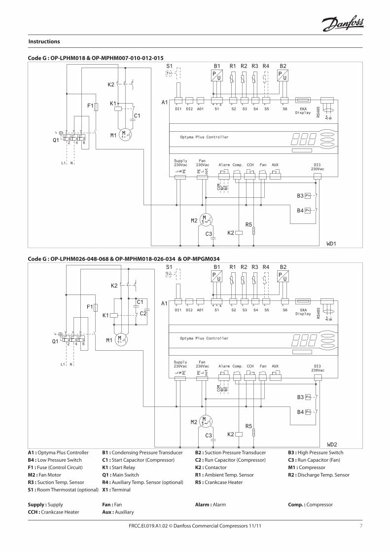
A1 : Optyma Plus Controller B1 : Condensing Pressure Transducer B2 : Suction Pressure Transducer B3 : High Pressure Switch
B4 : Low Pressure Switch C1 : Start Capacitor (Compressor) C2 : Run Capacitor (Compressor) C3 : Run Capacitor (Fan)
F1 : Fuse (Control Circuit) K1 : Start Relay K2 : Contactor M1 : Compressor
M2 : Fan Motor Q1 : Main Switch R1 : Ambient Temp. Sensor R2 : Discharge Temp. Sensor
R3 : Suction Temp. Sensor R4 : Auxiliary Temp. Sensor (optional) R5 : Crankcase Heater
S1 : Room Thermostat (optional) X1 : Terminal
Supply : Supply Fan : Fan Alarm : Alarm Comp. : Compressor
CCH : Crankcase Heater Aux : Auxiliary
Code G : OP-LPHM018 & OP-MPHM007-010-012-015
Code G : OP-LPHM026-048-068 & OP-MPHM018-026-034 & OP-MPGM034

FRCC.EI.019.A1.02 - November 2011 Copyright Danfoss Commercial Compressors - DSS - 11/11
Danfoss can accept no responsibility for possible errors in catalogues, brochures and other printed material. Danfoss reserves the right to alter its products without notice. This also applies to products already on order provided that such alterations can be made without subsequential changes being necessary in specifications already agreed. All trade-marks in this material are property of the respective companies. Performer®, Danfoss and the Danfoss logotype are trademarks of Danfoss A/S. All rights reserved.
Instructions
PU
B1PU
B2T>
S1
M1~M2
R5
P<B4
P>B3
F1
NL1
I > I > I >2 4 6Q1
COM
NC
NO
C2
M1~M1
K2
K2
R1 R2 R3
C3
WD3
DI1 DI2 S1 S2 S3 S4 S5AO1Display
EKAS6+ s
Alarm Comp. FanCCH AUX230Vac 230Vac
L LN PE
PE
DI3230Vac
out
Supply Fan
Optyma Plus Controller
RS485
A+
B-
A1
R4
PU
B1PU
B2T>
S1
M1~M2
R5
P<B4
P>B3
COM
NC
NO
K2
F1
I > I > I >2 4 6Q1
K2
M3~M1
NX1
R1 R2 R3
L1 L2 L2 N
C3
WD4
DI1 DI2 S1 S2 S3 S4 S5AO1Display
EKAS6+ s
Alarm Comp. FanCCH AUX230Vac 230Vac
L LN PE
PE
DI3230Vac
out
Supply Fan
Optyma Plus Controller
RS485
A+
B-
A1
R4
A1 : Optyma Plus Controller B1 : Condensing Pressure Transducer B2 : Suction Pressure Transducer B3 : High Pressure Switch
B4 : Low Pressure Switch C2 : Run Capacitor (Compressor) C3 : Run Capacitor (Fan) F1 : Fuse (Control Circuit)
K2 : Contactor M1 : Compressor M2 : Fan Motor Q1 : Main Switch
R1 : Ambient Temp. Sensor R2 : Discharge Temp. Sensor R3 : Suction Temp. Sensor R4 : Auxiliary Temp. Sensor (optional)
R5 : Crankcase Heater S1 : Room Thermostat (optional) X1 : Terminal
Supply : Supply Fan : Fan Alarm : Alarm Comp. : Compressor
CCH : Crankcase Heater Aux : Auxiliary
Code E : OP-LPHM048-068-096-136 & OP-MPUM034-046-068-080-107
Code G : OP-MPUM034-046-068-080