Embed Size (px)
Citation preview

Instructions
Condensing Units Optyma™ Integral range
© Danfoss | DCS (CC) | 2018.08 FRCC.PI.059.A1.ML | 1
English / English p. 2
Deutsch / German p. 10
Français / French p. 18
Polski / Polish p. 26

Instructions
2 | © Danfoss | DCS (CC) | 2018.08 FRCC.PI.059.A1.02
MBP application50 Hz Compressor H W D
OP-MCRN030OP-MCRN038
MTZ018MTZ022
545 630 650
OP-MCRN048OP-MCRN054OP-MCRN060
MTZ028MTZ032MTZ036
705 900 900
OP-MCRN068OP-MCRN086OP-MCRN096OP-MCRN108OP-MCRN121OP-MCRN136
MTZ040MTZ050MTZ056MTZ064MTZ072MTZ080
836.5 1200 800
OP-MGRN108OP-MGRN121OP-MGRN136
MTZ064MTZ072MTZ080
693.5 1500 870
OP-MGRN171OP-MGRN215OP-MGRN242OP-MGRN271
MTZ100MTZ125MTZ144MTZ160
836.5 1500 870
LBP application50 Hz Compressor H W D
OP-LCQN048 NTZ048 545 630 650OP-LCQN068 NTZ068 705 900 900OP-LCQN096OP-LCQN108OP-LCQN136
NTZ096 NTZ108NTZ136
836.5 1200 800
OP-LGQN096OP-LGQN108OP-LGQN136
NTZ096NTZ108NTZ136
693.5 1500 870
OP-LGQN215OP-LGQN271
NTZ215NTZ271
836.5 1500 870
-350
10
20
30
40
50
-30 -25 -20 -15 -10 -5 0 5 10 15
Evaporating Temperature (°C)
R404A/R507
Am
bien
t Tem
pera
ture
(°C)
-350
10
20
30
40
50
-30 -25 -20 -15 -10 -5 0 5 10 15
Evaporating Temperature (°C)
R448A/R449A
Am
bien
t Tem
pera
ture
(°C)
-350
10
20
30
40
50
-30 -25 -20 -15 -10 -5 0 5 10 15
Evaporating Temperature (°C)
R407A
Am
bien
t Tem
pera
ture
(°C)
0
10
20
30
40
50
-30 -25 -20 -15 -10 -5 0 5 10 15 20
Evaporating Temperature (°C)
R407C
Am
bien
t Tem
pera
ture
(°C)
-350
10
20
30
40
50
-30 -25 -20 -15 -10 -5 0 5 10 15
Evaporating Temperature (°C)
R452A
Am
bien
t Tem
pera
ture
(°C)
-350
10
20
30
40
50
-30 -25 -20 -15 -10 -5 0 5 10 15
Evaporating Temperature (°C)
R407F
Am
bien
t Tem
pera
ture
(°C)
0
10
20
30
40
50
-30 -25 -20 -15 -10 -5 0 5 10 15 20
Evaporating Temperature (°C)
R134a
Am
bien
t Tem
pera
ture
(°C)
SH = 10 K , SC = 0 KMBP (Fig.1a)
OptymaTM
by Danfoss
WD
H

Instructions
© Danfoss | DCS (CC) | 2018.08 | 3FRCC.PI.059.A1.02
1 x coil height Min. clearance: 2 x unit length
Fig.2
Fig.3
Fig.4
-450
10
20
30
40
50
-40 -35 -30 -25 -20 -15 -10 -5 0 5
Evaporating Temperature (°C)
R404A/R507
Am
bien
t Tem
pera
ture
(°C)
-450
10
20
30
40
50
-40 -35 -30 -25 -20 -15 -10 -5 0 5
Evaporating Temperature (°C)
R452A
Am
bien
t Tem
pera
ture
(°C)
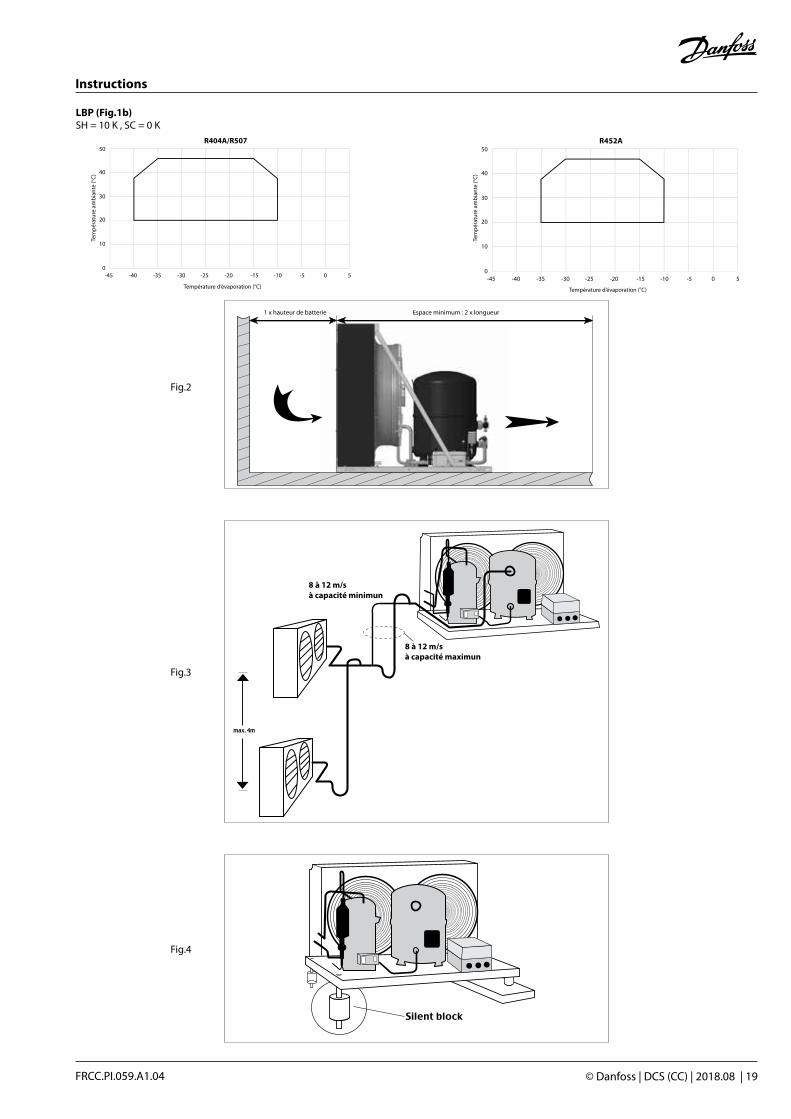
SH = 10 K , SC = 0 KLBP (Fig.1b)

Instructions
4 | © Danfoss | DCS (CC) | 2018.08 FRCC.PI.059.A1.02
SINGLE PHASE MODELS
THREE PHASE MODELS

Instructions
© Danfoss | DCS (CC) | 2018.08 | 5FRCC.PI.059.A1.02
For R404A models
Factory setting
HP (bar)
MBP 28 8
LBP 28 3
LP (bar)
Instructions
6 | © Danfoss | DCS (CC) | 2018.08 FRCC.PI.059.A1.02
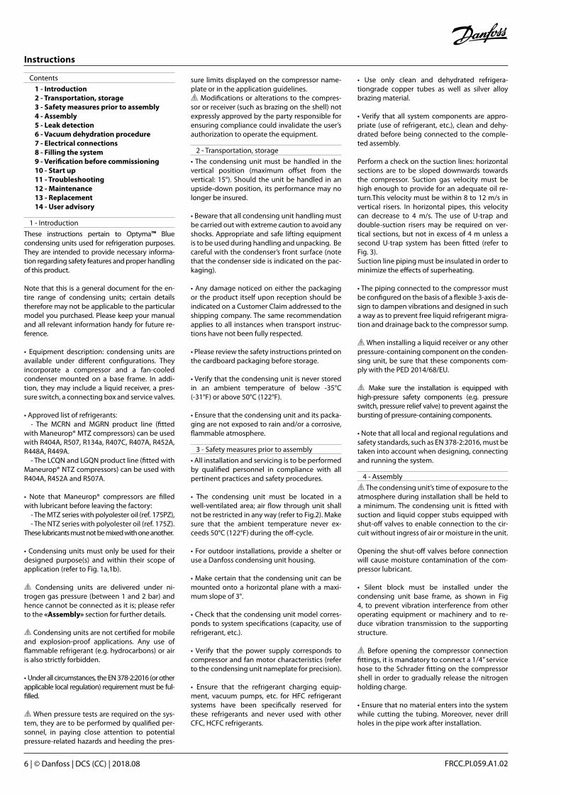
Contents
1 - Introduction 2 - Transportation, storage 3 - Safety measures prior to assembly 4 - Assembly 5 - Leak detection 6 - Vacuum dehydration procedure 7 - Electrical connections 8 - Filling the system 9 - Verification before commissioning 10 - Start up 11 - Troubleshooting 12 - Maintenance 13 - Replacement 14 - User advisory
1 - Introduction
These instructions pertain to Optyma™ Blue condensing units used for refrigeration purposes. They are intended to provide necessary informa-tion regarding safety features and proper handling of this product.
Note that this is a general document for the en-tire range of condensing units; certain details therefore may not be applicable to the particular model you purchased. Please keep your manual and all relevant information handy for future re-ference.
• Equipment description: condensing units are available under different configurations. They incorporate a compressor and a fan-cooled condenser mounted on a base frame. In addi-tion, they may include a liquid receiver, a pres-sure switch, a connecting box and service valves.
• Approved list of refrigerants: - The MCRN and MGRN product line (fitted with Maneurop® MTZ compressors) can be used with R404A, R507, R134a, R407C, R407A, R452A, R448A, R449A. - The LCQN and LGQN product line (fitted with Maneurop® NTZ compressors) can be used with R404A, R452A and R507A.
• Note that Maneurop® compressors are filled with lubricant before leaving the factory: - The MTZ series with polyolester oil (ref. 175PZ), - The NTZ series with polyolester oil (ref. 175Z).These lubricants must not be mixed with one another.
• Condensing units must only be used for their designed purpose(s) and within their scope of application (refer to Fig. 1a,1b).
Condensing units are delivered under ni-trogen gas pressure (between 1 and 2 bar) and hence cannot be connected as it is; please refer to the «Assembly» section for further details.
Condensing units are not certified for mobile and explosion-proof applications. Any use of flammable refrigerant (e.g. hydrocarbons) or air is also strictly forbidden.
• Under all circumstances, the EN 378-2:2016 (or other applicable local regulation) requirement must be ful-filled.
When pressure tests are required on the sys-tem, they are to be performed by qualified per-sonnel, in paying close attention to potential pressure-related hazards and heeding the pres-
sure limits displayed on the compressor name-plate or in the application guidelines.
Modifications or alterations to the compres-sor or receiver (such as brazing on the shell) not expressly approved by the party responsible for ensuring compliance could invalidate the user’s authorization to operate the equipment.
2 - Transportation, storage
• The condensing unit must be handled in the vertical position (maximum offset from the vertical: 15°). Should the unit be handled in an upside-down position, its performance may no longer be insured.
• Beware that all condensing unit handling must be carried out with extreme caution to avoid any shocks. Appropriate and safe lifting equipment is to be used during handling and unpacking. Be careful with the condenser’s front surface (note that the condenser side is indicated on the pac-kaging).
• Any damage noticed on either the packaging or the product itself upon reception should be indicated on a Customer Claim addressed to the shipping company. The same recommendation applies to all instances when transport instruc-tions have not been fully respected.
• Please review the safety instructions printed on the cardboard packaging before storage.
• Verify that the condensing unit is never stored in an ambient temperature of below -35°C (-31°F) or above 50°C (122°F).
• Ensure that the condensing unit and its packa-ging are not exposed to rain and/or a corrosive, flammable atmosphere.
3 - Safety measures prior to assembly
• All installation and servicing is to be performed by qualified personnel in compliance with all pertinent practices and safety procedures.
• The condensing unit must be located in a well-ventilated area; air flow through unit shall not be restricted in any way (refer to Fig.2). Make sure that the ambient temperature never ex-ceeds 50°C (122°F) during the off-cycle.
• For outdoor installations, provide a shelter or use a Danfoss condensing unit housing.
• Make certain that the condensing unit can be mounted onto a horizontal plane with a maxi-mum slope of 3°.
• Check that the condensing unit model corres-ponds to system specifications (capacity, use of refrigerant, etc.).
• Verify that the power supply corresponds to compressor and fan motor characteristics (refer to the condensing unit nameplate for precision).
• Ensure that the refrigerant charging equip-ment, vacuum pumps, etc. for HFC refrigerant systems have been specifically reserved for these refrigerants and never used with other CFC, HCFC refrigerants.
• Use only clean and dehydrated refrigera-tiongrade copper tubes as well as silver alloy brazing material.
• Verify that all system components are appro-priate (use of refrigerant, etc.), clean and dehy-drated before being connected to the comple-ted assembly.
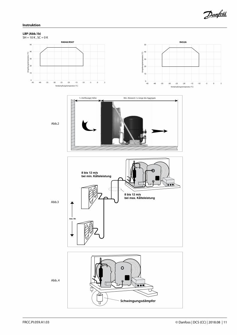
Perform a check on the suction lines: horizontal sections are to be sloped downwards towards the compressor. Suction gas velocity must be high enough to provide for an adequate oil re-turn.This velocity must be within 8 to 12 m/s in vertical risers. In horizontal pipes, this velocity can decrease to 4 m/s. The use of U-trap and double-suction risers may be required on ver-tical sections, but not in excess of 4 m unless a second U-trap system has been fitted (refer to Fig. 3).Suction line piping must be insulated in order tominimize the effects of superheating.
• The piping connected to the compressor must be configured on the basis of a flexible 3-axis de-sign to dampen vibrations and designed in such a way as to prevent free liquid refrigerant migra-tion and drainage back to the compressor sump.
When installing a liquid receiver or any other pressure-containing component on the conden-sing unit, be sure that these components com-ply with the PED 2014/68/EU.
Make sure the installation is equipped with high-pressure safety components (e.g. pressure switch, pressure relief valve) to prevent against the bursting of pressure-containing components.
• Note that all local and regional regulations and safety standards, such as EN 378-2:2016, must be taken into account when designing, connecting and running the system.
4 - Assembly
The condensing unit’s time of exposure to the atmosphere during installation shall be held to a minimum. The condensing unit is fitted with suction and liquid copper stubs equipped with shut-off valves to enable connection to the cir-cuit without ingress of air or moisture in the unit.
Opening the shut-off valves before connection will cause moisture contamination of the com-pressor lubricant.
• Silent block must be installed under the condensing unit base frame, as shown in Fig 4, to prevent vibration interference from other operating equipment or machinery and to re-duce vibration transmission to the supporting structure.
Before opening the compressor connection fittings, it is mandatory to connect a 1/4” service hose to the Schrader fitting on the compressor shell in order to gradually release the nitrogen holding charge.
• Ensure that no material enters into the system while cutting the tubing. Moreover, never drill holes in the pipe work after installation.

Instructions
© Danfoss | DCS (CC) | 2018.08 | 7FRCC.PI.059.A1.02
• Avoid flare-type connections and exercise great care while brazing (use only state-of-the-art practices); apply a nitrogen gas flow to prevent oxidation inside the tubing, especially when HFC refrigerants are being used. All brazing ma-terial is to contain a minimum of 5% silver.• When brazing, protect the valves and all other unit components from torch heat damage (painted surfaces, gaskets, connecting box).
• Note that it is not necessary to remove com-pressor shut-off valves for connection to the system, hence no need to replace associated gaskets.
• Be sure to connect the required safety and control devices onto compressor shut-off valves or fittings.
• In case of oil return through the Schrader fitting on the compressor shell, make sure the internal valve is removed.
5 - Leak detection
Never use oxygen or dry air in order to avoid the risk of fire or explosion.
• Perform a leak detection test on the complete system by means of: a dry nitrogen pressure test, a mixture of nitrogen and the refrigerant to be used in the system, a helium leak test and/or a deep vacuum test.
• The test should be long enough in duration to ensure the absence of any slow leaks in the sys-tem.
• Use tools specifically designed for detecting leaks.
• The low side test pressure must not exceed 1.1 x Ps pressure indicated on the compressor name-plate.
• For high side test pressure, do not exceed the pres-sure indicated on the condensing unit nameplate.
• Whenever the condensing unit is equipped with suction and liquid shut-off valves, these valves are to remain in the closed position while performing the leak test (condensing unit leak test already performed in the factory).
• Should a leak be discovered, proceed with re-pair steps and repeat the leak detection.
• When a deep vacuum leak detection test is se-lected, observe the following: 1) The level to reach is 500 μm Hg. 2) Wait 30 min. 3) If pressure increases rapidly, the system is not airtight. Locate and repair leaks. Restart the vacuum procedure, followed by steps 1, 2, etc. 4) If pressure increases slowly, the system contains moisture inside. Break the vacuum with nitrogen gas and restart the vacuum procedure, followed by steps 1, 2, etc. 5) Connect the compressor to the system by opening the valves. 6) Repeat the vacuum procedure, followed by steps 1, 2, etc. 7) Break the vacuum with nitrogen gas. 8) Repeat the vacuum procedure, steps 1, 2; a vacuum of 500 μm Hg (0.67 mbar) should be reached and maintained for 4 hours. This pres-
sure is to be measured in the refrigeration sys-tem, and not at the vacuum pump gauge.
Do not use a megohmeter or apply power to the compressor while it is under vacuum, as this may cause motor winding damage (motor burn-out).
Do not use colored leak detection fluids. Do not use chlorofluorocarbon in leak testing sys-tems designed for HFC fluids.
6 - Vacuum dehydration procedure
Whenever possible (if shut-off valves are pre-sent), the condensing unit must be isolated from the circuit. It is essential to connect the vacuum pump to both the LP & HP sides, in order to avoid dead-ending system parts.
Recommended procedure: 1) Once leak detection has been completed, 2) Pull down the system under a vacuum of 500 μm Hg (0.67 mbar). 3) When the vacuum level of 500 μm Hg has been reached, the system must be isolated from the pump. 4) A vacuum of 500 μm Hg (0.67 mbar) has to be reached and maintained for 4 hours. This pressure is to be measured in the refrigeration system, and not at the vacuum pump gauge.
If pressure increases, restart the leak-detection procedure (refer to the «Leak detection» section of this manual if necessary).
Vacuum pump:A two-stage vacuum pump with gas ballast valve (0,04-mbar standing vacuum) shall be used; its capacity is to be consistent with system volume. Never use the compressor as a vacuum pump. It is recommended to use large-diameter connec-tion lines and to connect these lines to the shut-off valves, rather than to the Schrader connec-tion.This recommendation allows avoiding excessive pressure losses.
Moisture level:At the time of commissioning, system moisture content may be as high as 100 ppm. During ope-ration, the liquid line filter dryer must reduce this level to < 20 ppm.
Additional notes:• To improve moisture removal, the temperature of the system should not be lower than 10°C.
• A proper vacuum procedure is even more im-portant with HFC and polyolester lubricant than it has “traditionally” been with HCFC (R22) or CFC and mineral oil.
• For further details, please refer to TI 3-026.
Do not use a megohmeter or apply power to the compressor while it is under vacuum, as this may cause motor winding damage (motor burn-out).
7 - Electrical connections
• Make sure the main power supply to the sys-tem has been switched off and isolated, in ac-cordance with applicable regulations, before performing any electrical connection.
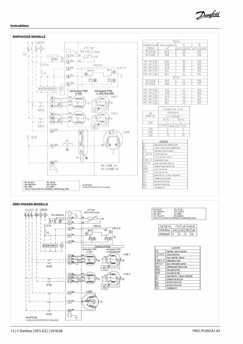
• Please refer to Figs 5 and 6 for typical wiring connections and examine the specific wiring diagram located in the electrical box cover.For further details, refer to the condensing unit guidelines.
• Note that Maneurop® compressors fitted on condensing units are protected against overhea-ting and overloading by an internal safety motor protector. However, an external manual reset overload is recommended for protecting the cir-cuit against over-current.
• The “must trip” value of this overload relay must be set in accordance with power line sizing and design and shall never exceed the “A max.” value stamped on the nameplate.
• On units equipped with an electrical box, all electrical connections (condenser fan motor, compressor motor, pressure control switch, crankcase heater, etc.) have already been wired at the factory. For single-phase compressors, start-and-run capacitors are included in the connec-ting box.
• The connecting box is equipped with screw type terminal blocks, for both power and control lines as well as earth terminals for grounding connections.
• All electrical components must be selected as per local standards and condensing unit compo-nent requirements.
8 - Filling the system
• Before charging the refrigerant, verify that the oil level is between 1/4 and 3/4 on the com-pressor oil sight glass and/or ensure that the oil charge of the original compressor is sufficient as regards system dimension and piping design: - An additional quantity of oil might be neces-sary for line lengths (back and forth) in excess of 20 m. - In the event additional oil is required, use only an approved lubricant (refer to the «Intro-duction» section of this manual).
• Make sure the refrigerant used to fill the system is compatible with compressor design. Refer to the «Introduction» section of this manual for an approved list of refrigerants.
• Compressor switched off: the liquid refrigerant is charged into the condenser and/or liquid re-ceiver in the liquid phase (compulsory for refri-gerant blends).The charge must be asclose to the nominal system charge as possible in order to avoid both low pressure operations and ex-cessive superheating at start-up. Throughout this operation, both compressor service valves must remain closed.
• To the extent possible, maintain the refrigerant charge below 2.5 kg per cylinder. Above this li-mit, install a system, such as a pump-down cycle or suction line accumulator, to prevent against liquid flood-back into the compressor.
• Be sure that the refrigerant charge is suitable for both winter and summer operations.

Instructions
8 | © Danfoss | DCS (CC) | 2018.08 FRCC.PI.059.A1.02
9 - Verification before commissioning
Ensure that all service valves are in the open position before start-up. A closed discharge or suction service valve may cause serious damage to the compressor and/or compromise safety device operation, thereby resulting in potential injury to personnel.• Check that all safety devices are operational and properly set (safety pressure switch set point, mechanical relief valve if necessary, etc.). Make sure that these devices comply with both generally - and locally - applicable regulations and standards (e.g. EN 378-2:2016).
• When using high-pressure switches or relief valves, the setting must not exceed maximum service pressure of any system component. Re-fer to the Application Guidelines for relevant condensing unit pressure safety limits.
• A low-pressure switch is recommended to prevent operation under vacuum. Use a mini-mum setting of 1.2 bar (absolute).
• Verify that all electrical connections are proper-ly fastened and in compliance with local safety regulations.
• A compressor crankcase heater is factory ins-talled, ensure that it has been energized for a minimum of 12 hours before initial start-up and/or during prolonged shutdown periods.
10 - Start up
Never start the compressor in the absence of a refrigerant charge.
• Do not bypass the LP or any other safety swit-ches during start-up
• Check current draw and voltage levels.
• Monitor the oil sight glass to ensure proper oil return to the compressor.After 2 to 4 hours of operations under established conditions, check the oil level and add oil if necessary (refer to TI bulletin 3-025).If oil return continues to perform poorly, further investigation of the piping design is required.
• In all cases, the application limits of the compressor must be respected; moreover, high superheat values lead to high discharge temperatures and decrease compressor capacity. The maximum discharge tem-perature is 130°C: operating at a higher temperature may result in refrigerant decomposition.
• Under steady-state operating conditions, check refrigerant piping or capillary tubes for abnor-mal vibrations (refrigeration line movement in excess of 1.5 mm necessitates corrective actions, pipe brackets, etc.).
• Ensure that refrigerant flow through the liquid line sight glass (when mounted) is adequate and that operating temperatures correspond with system specifications.
• When needed, refrigerant may be added in the liquid phase, carefully throttling the refrigerant on the low-pressure side and as far as possible from the compressor.The compressor must be operating during this process.
Do not overcharge the system.
11 - Troubleshooting
• Compressor failure to start: verify that the compressor is hooked up to the power supply; check the power lead connections and all sui-table capacitors on single-phase models. If these verifications reveal no abnormality, control the motor windings with an ohmmeter.
Note: when the internal motor protector has tripped out, it may take up to several hours to reset and restart the compressor.
• Compressor failure to build up pressure: check to make sure that all bypass valves in the system have not been opened. Also check that all solenoid valves are in their proper position. If the internal pressure relief valve is open, the compressor sump will be warm and the com-pressor will trip out on the motor protector. If this happens, it may take up to 2 or 3 hours to reset and automatically restart the compressor.
• Abnormal running noise on the system: - Ensure the absence of any liquid flood-back to the compressor by means of measuring the return gas superheat and compressor sump temperature. The sump should be at least 10K above the saturated suction temperature under steady-state operating conditions. - Check that the fans are running free and wit-hout vibration.
• The high-pressure switch trips out: check condenser operations (condenser cleanliness, fan operations, etc.). If above check out OK, the problem may be due to either refrigerant over-charging or the presence of a non-condensable (e.g. air, moisture) in the circuit.
• The low-pressure switch trips out: check eva-porator operations (coil cleanliness, fan opera-tions, water flow, water filter, etc.), liquid refrige-rant flow and pressure drops (solenoid valve, filter dryer, expansion valve, etc.), refrigerant charge.
• Low refrigerant charge: the correct refrige-rant charge is given by the liquid sight glass indication, the condenser delta T in relation to the refrigerant pressure tables (pressure-tempe-rature), the superheat and the sub-cooling, etc. (if additional charge is deemed necessary, refer to the «Filling the system» section).
• Compressor maximum short cycling: there must be a minimum delay of five minutes between two compressor starts. DCC recom-mends the compressor should run at least two minutes after each start, and between each stop and start must be three minutes standstill. Only during pump down cycle, the compressor may run much shorter until the pumpdown pressure has been reached or when safety devices will prohibit compressor further operation.
12 - Maintenance
• Proper operations and maintenance of the condensing units serve to prevent against sys-tem-related problems.The following preventive maintenance checks, to be performed at regular intervals, are highly recommended:
- Control operating conditions (evaporating temperature, condensing temperature, com-pressor discharge temperature, temperature difference on heat exchangers, superheat, sub-cooling). These conditions must always re-main within compressor operation limits. - Verify that safety devices are operational and properly set.
- Check the compressor oil level and quality; this step may include an acid test, humidity check, spectrometer analysis, etc. whenever the oil becomes discolored. - Ensure that the circuit is leak tight.
- Verify the proper operation of heat exchan-gers and, if necessary, clean them. - Check that the fans are running free (without vibration) and current draw on the compressor motor as well as proper voltage balance between phases. - Note 1: The condenser must be checked at least once a year for clogging and be cleaned if deemed necessary. Access to the internal side of the condenser takes place through the fan pa-nel.Microchannel coils tend to accumulate dirt on the surface rather than inside, which makes them easier to clean than fin-&-tube coils. - Change the filter dryer when necessary. - Check that all electrical connections are still adequately fastened. - Make sure the condensing unit is clean and in good working order; verify the absence of rust or corrosion on components under pressure and electrical connections. - Make sure the refrigerant charge is suitable for both winter and summer operation.• Ensure that periodic in-service inspections re-quired by local regulations are performed. - Note 2: Remove surface dirt, leaves, fibers, etc. with a vacuum cleaner, equipped with a brush or other soft attachment. Alternatively, blow compressed air through the coil from the inside out, and brush with a soft bristle.Do not use a wire brush. Do not impact or scrape the coil with the vacuum tube or air nozzle.
13 - Replacement
Precaution must be taken when disconnec-ting any components, cutting or drilling holes in the tubing to ensure that no refrigerant under pressure is present in the system.
The refrigerant shall not be discharged direc-tly into the atmosphere; rather, it must be remo-ved using approved reclamation techniques and equipment and then safely stored, inaccordance with applicable legislation.
The presence of refrigerant vapor can displace air and lead to suffocation. Proper ventilation is mandatory at all times when servicing the equip-ment.
A condensing unit component change must be carried out in compliance with local regulations.
• Make sure that the main power supply has been switched off.
• Before replacement, it is necessary to deter-mine the cause of failure and implement reme-dial action. If such analysis and repair are not
Instructions
© Danfoss | DCS (CC) | 2018.08 | 9FRCC.PI.059.A1.02
performed, repetitive failure may occur. Note that an oil acidity test always proves helpful in-diagnosis when undertaking compressor repla-cement.
• Check that the replacement component has the same electrical and refrigeration perfor-mance characteristics as the original one.
• Whenever piping needs to be modified, please refer to the «Safety measures prior to assem-bly» section.
• For further details on replacement steps,refer to the previous sections of this manual.
Note: In the event of compressor motor failure, flush and clean the entire circuit before replacing the compressor in order to remove acids and conta-minants. Systematically install a new filter dryer on the liquid line. Prior to this step (if necessary), run the system for at least 2 hours with anti-acid cartridges (in such instances, the installation of a suction filter might also be required). After an ope-rating period of approximately 2 weeks, check the level of oil acidity. If the oil acid test proves positive, drain and replace the oil, replace the anti-acid li-quid line filter dryer cartridges and the suction filter previously installed. Repeat oil and filter dryer re-placements until the system is clean and acid-free.When there is no longer any sign of acidity, replace
the anti-acid cartridges by the standard model and remove the suction strainer cartridge as required.
14 - User advisory
Insist that all service operations only be per-formed by qualified personnel.
The condensing unit tubing and compressor surface temperatures may exceed 100°C (212°F) and cause severe bodily burns. Special precau-tion must be taken when working around the compressor and refrigerant tubing. Moreover, a compressor in operation can generate very cold surface temperatures (as low as -45°C / -49°F), there by exposing personnel to the risk of free-zing burns.
Pressure inside the compressor and refrige-rant circuit can reach dangerously high levels (e.g. abnormal operation, fire,…) leading to personnel injury if suddenly released; therefore, never drill, weld or cut the compressor shell and adjacent tubing (release of liquid refrigerant can cause flash freezing on exposed skin).
Even though fans are fitted with safety guard it is recommended not to work on condenser while fans are running.
Be aware that the product warranty may be deemed null and void in the following cases:
• Modifications to the unit, unless approved by Danfoss Commercial Compressors, absence of nameplate, broken or dented components, shock marks, etc...• Compressor opened by the customer or re-turned unsealed (i.e. open discharge or suction ports),
• Presence of rust or water inside the condensing unit circuit,
• Addition of leak-detection fluid in the compres-sor lubricant,
• Use of a refrigerant or lubricant not approved by Danfoss Commercial Compressors.,
• Any deviation from recommended instructions-pertaining to installation, application or mainte-nance,
• Use in mobile applications (boats, trains, truc-ks,etc.) or under explosive atmospheric conditions.
The date of production of the condensing unit is indicated on the nameplate. Ensure that the model and serial number information is always transmitted with any claim filed regarding this product.

MBP Anwendung50 Hz Verdichter H W D
OP-MCRN030OP-MCRN038
MTZ018MTZ022
545 630 650
OP-MCRN048OP-MCRN054OP-MCRN060
MTZ028MTZ032MTZ036
705 900 900
OP-MCRN068OP-MCRN086OP-MCRN096OP-MCRN108OP-MCRN121OP-MCRN136
MTZ040MTZ050MTZ056MTZ064MTZ072MTZ080
836.5 1200 800
OP-MGRN108OP-MGRN121OP-MGRN136
MTZ064MTZ072MTZ080
693.5 1500 870
OP-MGRN171OP-MGRN215OP-MGRN242OP-MGRN271
MTZ100MTZ125MTZ144MTZ160
836.5 1500 870
LBP Anwendung50 Hz Verdichter H W D
OP-LCQN048 NTZ048 545 630 650OP-LCQN068 NTZ068 705 900 900OP-LCQN096OP-LCQN108OP-LCQN136
NTZ096 NTZ108NTZ136
836.5 1200 800
OP-LGQN096OP-LGQN108OP-LGQN136
NTZ096NTZ108NTZ136
693.5 1500 870
OP-LGQN215OP-LGQN271
NTZ215NTZ271
836.5 1500 870
Instruktion
10 | © Danfoss | DCS (CC) | 2018.08 FRCC.PI.059.A1.03
SH = 10 K , SC = 0 KMBP (Abb.1a)
-350
10
20
30
40
50
-30 -25 -20 -15 -10 -5 0 5 10 15
Evaporating Temperature (°C)
R404A/R507
Am
bien
t Tem
pera
ture
(°C)
Um
geb
ungs
tem
per
atur
(°C
)
Verdampfungstemperatur (°C)
-350
10
20
30
40
50
-30 -25 -20 -15 -10 -5 0 5 10 15
Evaporating Temperature (°C)
R448A/R449A
Am
bien
t Tem
pera
ture
(°C)
Verdampfungstemperatur (°C)
Um
geb
ungs
tem
per
atur
(°C
)
-350
10
20
30
40
50
-30 -25 -20 -15 -10 -5 0 5 10 15
Evaporating Temperature (°C)
R407A
Am
bien
t Tem
pera
ture
(°C)
Verdampfungstemperatur (°C)
Um
geb
ungs
tem
per
atur
(°C
)
0
10
20
30
40
50
-30 -25 -20 -15 -10 -5 0 5 10 15 20
Evaporating Temperature (°C)
R407C
Am
bien
t Tem
pera
ture
(°C)
Verdampfungstemperatur (°C)
Um
geb
ungs
tem
per
atur
(°C
)
0
10
20
30
40
50
-30 -25 -20 -15 -10 -5 0 5 10 15 20
Evaporating Temperature (°C)
R134a
Am
bien
t Tem
pera
ture
(°C)
Verdampfungstemperatur (°C)
Um
geb
ungs
tem
per
atur
(°C
)
-350
10
20
30
40
50
-30 -25 -20 -15 -10 -5 0 5 10 15
Evaporating Temperature (°C)
R452A
Am
bien
t Tem
pera
ture
(°C)
Verdampfungstemperatur (°C)
Um
geb
ungs
tem
per
atur
(°C
)
-350
10
20
30
40
50
-30 -25 -20 -15 -10 -5 0 5 10 15
Evaporating Temperature (°C)
R407F
Am
bien
t Tem
pera
ture
(°C)
Verdampfungstemperatur (°C)
Um
geb
ungs
tem
per
atur
(°C
)
OptymaTM
by Danfoss
WD
H
Instruktion
© Danfoss | DCS (CC) | 2018.08 | 11FRCC.PI.059.A1.03
Abb.3
Abb..4
SH = 10 K , SC = 0 KLBP (Abb.1b)
-450
10
20
30
40
50
-40 -35 -30 -25 -20 -15 -10 -5 0 5
Evaporating Temperature (°C)
R404A/R507
Am
bien
t Tem
pera
ture
(°C)
Um
geb
ungs
tem
per
atur
(°C
)
Verdampfungstemperatur (°C)-45
0
10
20
30
40
50
-40 -35 -30 -25 -20 -15 -10 -5 0 5
Evaporating Temperature (°C)
R452A
Am
bien
t Tem
pera
ture
(°C)
Um
geb
ungs
tem
per
atur
(°C
)
Verdampfungstemperatur (°C)
1 x coil height Min. clearance: 2 x unit length
Abb.2
1 x Verflüssiger-Höhe Min. Abstand: 2 x Länge des Aggregats
Instruktion
12 | © Danfoss | DCS (CC) | 2018.08 FRCC.PI.059.A1.03
EINPHASIGE MODELLE
DREI-PHASEN-MODELLE

Instruktion
© Danfoss | DCS (CC) | 2018.08 | 13FRCC.PI.059.A1.03
KP 15 060-1154, 060-1220, 060-1261, 060-1263, 060-1283
ND-man ND-auto ND-auto ND-manHD-man HD-man HD-auto HD-auto
ND, man. ResetND, auto. Reset
AC1 16 A DC 11LR 112A AC3 16 A 400 V � 12 W
AC11 10 A 220 V �
Bei UL-konformem Einsatz
-1 bar (Pe)(30in.Hg)
KP 15, 15A, 17W, 17B
KP17W/B 060-539366, 060-539466
ND-auto ND-autoHD-man HD-auto
Einschalten
ND HD
ND HD
Differenz Feste Differenz
Ausschalten
Manueller Test
Einschalten
Anzugsmoment 2,5 NmNur Kupferleitungen verwenden
Ausschalten
Manueller Reset
SPDT+ND Signal
ND ND HD
HD
ND+HD Signal
Werkseinstellung
Manueller Reset
Umschaltbarer Reset (W/B)
Umschaltbarer Reset (W/B)
Feste Differenz
Ausschalten
Einschalten
HD
ND Diff.
ND
für R404a Modelle
HP (bar)
MBP 28 8
LBP 28 3
LP (bar)
Werkseinstellung
Instruktion
14 | © Danfoss | DCS (CC) | 2018.08 FRCC.PI.059.A1.03
Inhalt
1 - Einleitung 2 - Transport, Lagerung 3 - Sicherheitsmaßnahmen vor dem Ein-
bau 4 - Montage 5 - Feststellen von Leckagen 6 - Evakuierung - Trocknung 7 - Elektrische Anschlüsse 8 - Befüllen der Anlage 9 - Überprüfung vor der Inbetriebna-
hme 10 - Inbetriebnahme 11 - Fehlerbehebung 12 - Wartung 13 - Austausch 14 - Betriebsanweisungen
1 - Einleitung
Diese Instruktion behandelt Optyma™ Blue Verflüssigungssätze für den Einsatz in Kältean-lagen. Sie soll dazu dienen, die für die Sicherheit im Umgang mit diesem Produkt und die für die ordnungsgemäße Handhabung erforderlichen Informationen bereitzustellen. Bitte beachten Sie, dass das vorliegendes Doku-ment als generelle Information für die gesamte Baureihe von Verflüssigungssätzen anzuse-hen ist. Bestimmte Details gelten daher für ein bestimmtes von Ihnen erworbenes Modell möglicherweise nicht. Es ist äußerst ratsam, diese Bedienungsanleitung vor Ort an der An-lage zu deponieren, um ggf. Details und Ver-fahrens-weisen nachschlagen zu können.• Gerätebeschreibung: Verflüssigungssätze sind in verschiedenen Ausführungen erhältlich. Sie bestehen aus einem Verdichter und einem luftgekühlten Verflüssiger, die beide auf einem Grundrahmen montiert sind. Darüber hinaus können, je nach Ausführung, ein Flüssigkeits-sammler, ein Druckschalter, ein Anschlusskasten und Serviceventile vormontiert sein.• Liste der freigegebenen Kältemittel: - Die MCRN- und MGRN-, Baureihe (bestückt mit Danfoss Maneurop® MTZ-Verdichter) darf mit R404A, R507, R134a, R407C, R407A, R452A R448A, R449A betrieben werden. - Die LCQN-, und LGQN- Baureihe (bestückt mit Danfoss Maneurop® NTZ- Verdichter) darf mit R404A, R452A und R507 betrieben werden.• Bitte beachten, dass Danfoss Maneurop® Ver-dichter vor der Auslieferung im Werk mit Kälte-maschinenöl vorgefüllt werden: - Die MTZ-Baureihe mit Polyolester 175PZ. - Die NTZ- Baureihe mit Polyolester 175Z.Diese Öle dürfen nicht gemischt werden.• Verflüssigungssätze dürfen nur für den urs-prünglich vorgesehenen Verwendungszweck in der Kältetechnik und innerhalb ihres Anwendungs bereichs zum Einsatz kommen (siehe Abb. 1a,1b).
Verflüssigungssätze werden mit einer Stickstoffschutzgasfüllung in leichtem Über-druck (zwischen 1 und 2 bar) geliefert und können in diesem Auslieferungszustand nicht sofort in Betrieb genommen werden. Siehe Abschnitt “Montage” für weitere Details.
Diese Verflüssigungssätze sind nicht für den mobilen Einsatz oder für den Betrieb in explo-sionsgefährdeten Bereichen zugelassen. Jedwe-de Verwendung von entflammbaren Kältemitteln (z.B. Kohlenwasserstoffe) oder Luft als Kältemittel oder Kältemittelersatz ist strengstens untersagt.
• Unter allen Umständen müssen die Anfor-derungen der EN 378-2:2016 erfüllt werden (oder eine andere zutreffende lokale Norm).
Etwaige Druckprüfungen der Anlage dürfen nur von qualifiziertem Personal vorgenommen werden, welches Kenntnis über die Gefahren im Zusammenhang mit druckbeaufschlagten Bau-teilen hat. Die am Verdichtertypenschild bzw. in den Anwendungsrichtlinien angegebenen Druckgrenzen sind zu beachten.
Modifikationen an Verdichter oder Sam-mler (wie hartlöten am Gehäuse), die nicht aus-drücklich von Danfoss genehmigt sind, können zum Erlöschen der Betriebserlaubnis des Gerätes führen.
2 - Transport, Lagerung
• Der Verflüssigungssatz darf nur in horizontaler Position (maximale Neigung von der Horizon-talen (parallel zur Grundplatte): 15°) bewegt und gelagert werden. Sollte der Verflüssigungssatz einmal umgedreht (wenn auch nur kurzzeitig) worden sein, kann dies bis zur Funktionstüchtig-keit des Gerätes führen.• Bitte beachten, dass alle Handhabungen des Ver-flüssigungssatzes mit äußerster Sorgfalt erfolgen sollen, um Stöße und damit äußerliche, aber auch innere Beschädigungen zu vermeiden. Für die Handhabung und beim Auspacken sind geeignete und sichere Hebewerkzeuge einzusetzen. Die Frontverkleidung des Verflüssigers ist sorgfältig zu behandeln (die Verflüssigerseite ist auf der Ver-packung speziell gekennzeichnet), da sich dort die empfindlichen Lamellen des Wärmetauschers be-finden.• Beschädigungen, die beim Warenempfang en-tweder an der Verpackung oder dem Produkt selbst erkennbar sind, müssen beim Transport-unternehmen schriftlich als Reklamation an-gezeigt werden. Die gleiche Empfehlung gilt für die Fälle, in denen die Transportanweisungen nicht eingehalten wurden. • Bitte hinsichtlich der Lagerung, die auf dem Verpackungskarton aufgedruckten Sicherheit-sanweisungen beachten.• Es ist dafür zu sorgen, dass der Verflüssig-ungssatz nicht bei Umgebungstemperaturen unter -35°C oder über 50°C gelagert wird.• Bitte stellen sie sicher, dass der Verflüssig-ungssatz und seine Verpackung nicht Regen und/ oder korrosiver oder entflammbarer At-mosphäre ausgesetzt wird.
3 - Sicherheitsmaßnahmen vor dem Einbau
• Alle Montage- oder Wartungsarbeiten sind in Übereinstimmung mit den einschlägigen Nor-men und dem Stand der Technik von geschultem Personal vorzunehmen.• Der Verflüssigungssatz muss an einem gut belüf teten Platz montiert werden. Der Luftaus-tausch am Verflüssigungssatz sollte ungehin-dert stattfinden können (siehe Abb. 2). Die Umgebungs temperatur während der Stills-tandsperiode darf zu keinem Zeitpunkt 50°C übersteigen.• Bei Installationen im Freien sollte ein Schutz-dach vorgesehen, oder ein Danfoss Wetter-schutzgehäuse benutzt werden.• Der Verflüssigungssatz soll auf einer waagere-chten Ebene mit einer maximalen Neigung von 3° montiert werden.• Das gewählte Verflüssigungssatzmodell muß mit den Anlagenspezifikationen (Kälteleistung, Kältemittel etc.) korrespondieren.
• Bitte orientieren sie sich bei der Spannungs- und Stromversorgung an den Kennwerten der Verdi-chter- und Lüftermotoren (siehe genaue Angaben auf dem Typenschild des Verflüssigungs satzes).• Die Monteurhilfe (Manometerbatterie) und die Vakuumpumpe etc. für HFKW-Kältemittel sollten ausschließlich für diese Kältemittel eingesetzt und nicht für FCKW-/HFCKW-Kältemittel glei-chermaßen benutzt werden.• Bitte verwenden sie ausschließlich saubere, trockene und für Kälteanlagen geeignete Kupferrohre sowie silberlegiertes Hartlötmate-rial.• Es ist wichtig, dass alle Anlagenkomponenten sau-ber und trocken sind, bevor sie montiert werden.• Bitte beachten sie den Saugleitungsverlauf: Horizontale Abschnitte sollten leicht zum Verdichter hin geneigt sein. Die Sauggas-geschwindigkeit muss hoch genug sein, um die Ölrückführung gewährleisten zu können. Diese Geschwindigkeit muss in Steigleitungen zwischen 8 bis 12 m/s liegen. In horizontalen Leitungsabschnitten darf die Geschwindigkeit auf 4 m/s abfallen. Ölhebe- und Ölüberbögen sowie doppelte Steigleitungen können bei ver-tikalen Abschnitten erforderlich sein. Maximal 4 m sollte der Abstand zwischen zwei Ölhebebö-gen bzw. einem Bogen und Überbogen in einer vertikalen Leitung mit Strömungsrichtung nach oben betragen (siehe Abb. 3). Die Saugleitung sollte isoliert werden, um Kondenswasser- bzw. Eisbildung und unnötig große Überhitzungen zu vermeiden. • Die bauseits am Verdichter montierten Leitungen sollten frei schwingen können, um ein gewisses Maß an Vibrationen absorbieren zu können. Außerdem sollte die Saugleitung so verlegt wer-den, dass eine Migration von flüssigem Kältemittel ins Kurbelgehäuse des Verdichters nicht begüns-tigt wird.
Im Falle einer Nachrüstung eines Verflüs-sigungs satzes mit einem Flüssigkeitssammler oder anderer druckbeaufschlagter Bauteile müssen diese der Druckgerät e-richtlinie 2014/68/EU bzw. der einschlägigen lokalen Normen entsprechen.
Um dem Bersten von druckbeaufschlagten Bauteilen vorzubeugen, sind additiv Hochdruck-sicherheitseinrichtungen (z.B. Druckschalter, Si-cherheitsventil) vorzusehen, sofern diese nicht schon vormontiert sind.• Bitte beachten, dass alle lokalen und regionalen Regelungen und Sicherheitsnormen (wie z.B. die Norm EN 378-2:2016) beim Aufbau, Anschluss und dem Betrieb der Anlage zu berücksichtigen sind.
4 - Montage
Die Zeitdauer, in der das Innere des Verflüs-sigungs satzes der Atmosphäre ausgesetzt wird, soll auf ein Mindestmaß beschränkt werden. Der Verflüssigungssatz ist mit Saug- und Flüssig-keitsabsperrventilen ausgestattet, um z.B. bei der Montage der restlichen Rohrleitungen den Verflüs-siungssatz noch geschlossen halten zu können.Die Absperrventile sollten erst nach Abschluss der Montagearbeiten geöffnet werden, da sonst die Gefahr besteht, dass Feuchtigkeit eindringt und dadurch das Kältemaschinenöll im Verdich-ter verunreinigt wird.• Ein Silentblock (Schwingungsdämpfer) muss unter dem Grundrahmen des Verflüssigungssa-tzes montiert werden, wie in Abb. 4 gezeigt, um Störungen durch Schwingungen von anderen laufenden Geräten oder Maschinen zu verhin-

Instruktion
© Danfoss | DCS (CC) | 2018.08 | 15FRCC.PI.059.A1.03
dern und die Schwingungsübertragung an die Trägerstruktur zu verringern.
Vor dem Öffnen der Verdichteran-schlusss-tutzen ist zum langsamen Ablassen der Stickstoff füllung ein “Manometerbatte-rie-Schlauch” an das auf dem Verdichtergehäuse befindliche Schraderventil anzuschließen.• Es ist dafür zu sorgen, dass beim Rohrab-schneiden kein Abfallmaterial (z.B. Kupferspäne) im Kältekreislauf verbleibt. Außerdem dürfen aus diesem Grund keine nachträglichen Bohrun-gen am fertig montierten Kältesystem vorge-nommen werden, wenn nicht sichergestellt werden kann, dass alle Kupferspäne entfernt werden können. • Bördelanschlüsse sind zu vermeiden und beim Hartlöten ist große Sorgfalt walten zu lassen. Trockener Stickstoff ist durch die Leitungen beim Löten strömen zu lassen, um Zunder im In-neren der Rohre zu vermeiden, besonders wenn HFKW-Kältemittel zum Einsatz kommen. Das Lötmaterial muss mindestens 5% Silber en-thalten, zu empfehlen bei Kupfer- Kupfer- Ver-bindungen ist ein Lot mit 15% Silberanteil.• Beim Hartlöten sind die Ventile und alle ande-ren Bauteile des Verflüssigungssatzes (lackierte Oberflächen, Dichtungen, Anschlusskasten) vor Hitzeschäden durch den Brenner zu schützen.• Beim Anschluss an die Anlage müssen die Abs-perrventile des Verdichters nicht demontiert werden. Deshalb ist es auch nicht erforderlich, die dazugehörigen Dichtungen auszutauschen.• Es ist dafür zu sorgen, dass die erforderlichen Sicherheits- und Überwachungseinrichtungen an die Absperrventile bzw. Anschlüsse des Ver-dichters angeschlossen werden.• Falls die Ölrückführung durch das Schrader-ventil am Verdichtergehäuse erfolgt, ist der in-nere Einsatz am Ventil zu entfernen.
5 - Feststellen von Leckagen
Zur Druckprobe der Anlage niemals reinen Sauerstoff oder trockene Luft benutzen. Dabei besteht Feuer- bzw. Explosionsgefahr.• Ein Leckagetest sollte für die gesamte Anlage entweder als Drucktest mit trockenem Stickstoff, Helium-Lecktest und/oder Tiefvakuumtest durchgeführt werden.• Der Test sollte lange genug dauern, um auch kleinste Leckagen in der Anlage sicher ausschließen zu können.• Für die Lecksuche gibt es Spezialgeräte. Bitte ggf. auf dieses Werkzeug zurückgreifen.• Der Testdruck auf der Niederdruckseite darf den 1,1-fachen Wert des auf dem Verdichter-typenschild angegebenen Ps-Drucks nicht über-schreiten.• Der Testdruck auf der Hochdruckseite darf den auf dem Typenschild für den Verflüssigungssatz ange-gebenen maximalen Druck nicht überschreiten.• Ist der Verflüssigungssatz mit Absperrventilen für Saug- und Druckseite ausgerüstet, können diese Ventile während der Durchführung des Lecktests getrost geschlossen gehalten bleiben (jeder Verflüssigungssatz wird bereits im Werk 100% auf etwaige Leckagen getestet).• Beim Auftreten einer Leckage sollte diese beseitigt und der Lecktest wiederholt werden.• Bei einem Tiefvakuumtests ist folgendes zu beachten: 1) Das zu erreichende Niveau beträgt 500 µm Hg (0,67 mbar). 2) 30 Minuten warten. 3) Steigt der Druck deutlich an, ist die Anlage
nicht dicht. Bitte die Leckagen beseitigen und mit dem Vakuumverfahren erneut von vorne be-ginnen. 4) Steigt der Druck langsam an, ist in der An-lage Feuchtigkeit. Das Vakuum sollte mit trocke-nem Stickstoff gebrochen und das Vakuumver-fahren erneut begonnen werden. 5) Den Verdichter durch Öffnen der Ventile mit der Anlage verbinden. 6) Das Vakuumverfahren erneut durchführen, gefolgt von den Schritten 1, 2, etc. 7) Das Vakuum mit Stickstoff brechen. 8) Das Vakuumverfahren, Schritte 1 und 2, wiederholen; ein Vakuum von 500 mHg (0,67 mbar) muss erzielt und 4 Stunden lang gehalten werden können. Dieser Druck ist an der Kältean-lage selbst und nicht mit dem Manometer der Vakuumpumpe zu messen.
Steht der Verdichter unter Vakuum, bitte kein Multimessgerät oder Kurbelinduktor benutzen. Generell keine Spannung anden Verdichter an-legen, wenn dieser unter Vakuum steht, da dies Schäden an der Motorwicklung verursachen kann (durchbrennen des Motors).
Bitte keine farbigen Lecksuchmittel verwen-den. Keine Chlorfluorkohlenwasserstoffe bei Tests in für HFKW-Kältemittel ausgelegten Anla-gen benutzen.
6 - Evakuierung - Trocknung
Soweit möglich (falls Absperrventile vorhan-den sind) ist der Verflüssigungssatz von der restlichen Anlage abzuschiebern. Die Vakuum-pumpe sollte immer sowohl an der Niederdruck- als auch an die Hochdruckseite angeschlossen sein, um alle Anlagenteile gut evakuieren zu können.Empfohlene Vorgehensweise: 1) Nach Abschluss der Lecksuche, 2) ist der Druck in der Anlage auf ein Vakuum von 500 mHg (0,67 mbar) abzusenken. 3) Sobald das Vakuum 500 mHg erreicht, die Pumpe von der Anlage trennen. 4) Das Vakuum von 500 mHg (0,67 mbar) 4 Stunden lang halten. Dieser Druck soll an der Kälteanlage und nicht mit dem Manometer an der Vakuumpumpe gemessen werden.Steigt der Druck an, ist die Lecksuche erneut vorzunehmen (falls erforderlich siehe Abschnitt «Feststellen von Leckagen» in dieser Bedienun-gsanleitung).Vakuumpumpe:Eine zweistufige Vakuumpumpe mit Gasballast (0,04 mbar stehendes Vakuum) sollte verwendet werden. Die Leistung der Vakuumpumpe sollte in Relation zum Anlagenvolumen stehen. Keinesfalls den Verdichter als Vakuumpumpe einsetzen. Es empfiehlt sich, großzügig bemessene Anschlus-sleitungen zu benutzen und diese vorzugsweise an Rotolock-Absperrventile anzuschließen, statt an Schraderanschlüsse mit Schraderventilen. Feuchtigkeitsgehalt:Zum Zeitpunkt der Inbetriebnahme darf der Feuchtigkeitsgehalt bis zu 100 ppm betragen. Während des Betriebs muss der in die Flüssig-keitsleitung eingebaute Filtertrockner diesen Anteil auf <20 ppm herabsetzen. Zusatzbemerkungen:• Um das Entfernen der Feuchtigkeit zu erleich-tern, sollte die Anlagentemperatur nicht weni-ger als 10°C betragen. • Bei Anlagen mit HFKW- Kältemitteln mit Polyo-lester-Öl ist ein sorgfältiges Evakuieren sogar noch wichtiger als bei Anlagen mit H-FCKW (z.B.
R22) oder FCKW mit Mineralöl.• Steht der Verdichter unter Vakuum, darf kein
Multimessgerät oder Kurbelinduktor verwendet werden, da dies Schäden an der Motorwicklung verursachen könnte (durchbrennen des Motors).
7 - Elektrische Anschlüsse
• Bitte stellen sie sicher, dass die Stromver-sorgung zum Verflüssigungssatz ausgeschaltet ist, bevor die elektrischen Anschlüsse vorge-nommen werden.• Die elektrischen Anschlüsse bitte gemäß Abb.5 und 6 bzw. des Anschlussschemas im Deckel des Anschlusskastens ausführen. Für weitere Details sie-he diese Verflüssigungssatz-Bedienungsanleitung.• Bitte beachten, dass in Verflüssigungssätzen eingebaute Danfoss Maneurop® Verdichter durch einen internen Motorschutzschalter vor Übertemperatur und Überlast geschützt sind. Es empfiehlt sich jedoch, jeweils einen externen Überstromauslöser mit manueller Rückstellung als Verdichter- und Verflüssigerlüfter-Motor-schutz vorzusehen.• Der «Auslösewert» dieses Überlastrelais soll in Übereinstimmung mit den Stromaufnahme-daten bemessen und eingestellt werden, darf jedoch nicht den am Typenschild angegebenen Wert «A max.» übersteigen.• Bei mit einem elektrischen Schaltkasten aus-gerüsteten Aggregaten werden alle elektrischen Anschlüsse (Verflüssigerlüftermotor, Verdich-termotor, Druckschalter, Kurbelwellen heizung, usw.) bereits in der Fabrik vorgenommen und in den Anschlusskasten geführt. Bei einphasigen Verdichtern sind die Start- und Betriebskonden-satoren im Schaltkasten des Verflüssigungssatzes zu finden. • Der Anschlusskasten ist mit Blockklemmen in verschraubbarer Ausführung sowohl für die Laststrom- als auch für die Steuerspannun-gsanschlüsse sowie Erdungsklemmen bestückt.Sämtliche elektrischen Komponenten sind gemäß der lokalen Standards und entsprechend der Verflüssigungssatzspezifikation auszuwählen.
8 - Befüllen der Anlage
• Vor dem Befüllen mit Kältemittel ist dafür zu sorgen, dass der Ölstand im Verdichterölschau-glas zwischen 1/4 und 3/4 beträgt und ob somit die ursprüngliche Ölfüllung des Verdichters für die Größe der Anlage und die Verrohrung aus-reicht. - Öl nachzufüllen kann bei Rohrlängen (hin und zurück) von über 20 m erforderlich werden. - Falls zusätzliches Öl erforderlich sein sollte, bitte nur ein von Danfoss freigegebenes Öl verwenden (siehe Abschnitt «Einleitung» zu Be-ginn dieser Betriebsanleitung).Bitte beachten, dass das für die Anlage vorgesehe-ne Kältemittel für den entsprechenden Verdichter freigegeben sein muß (siehe Abschnitt «Einlei-tung» zu Beginn dieser Betriebsanleitung. Dort finden sie eine Liste der zugelassenen Kältemittel).• Verdichter läuft nicht: Flüssiges Kältemittel wird in den Verflüssiger bzw. den Flüssigkeitssammler (obligatorisch für zeotrope Kältemittelgemische) gefüllt. Die Kätemittelfüllung sollte der von ih-nen errechneten Systemfüllung entsprechen, um Niederdruckabschaltung und zu hohe Überhit-zungen zu verhindern. Während dieses Vorgangs sind beide Verdichterserviceventile geschlossen zu halten.• So weit möglich ist die Kältemittelfüllmenge auf unter 2,5 kg gerechnet pro Zylinder (z.B.

Instruktion
16 | © Danfoss | DCS (CC) | 2018.08 FRCC.PI.059.A1.03
MTZ 64, zwei Zylinder, entspricht 5 kg max. Gesamtfüll menge) zu beschränken. Oberhalb dieser Grenze ist in der Anlage eine Pump-down-Schaltung oder ein Flüssigkeitsabscheider zu installieren, um der Verlagerung von flüssigem Kältemittel in den Verdichter vorzubeugen.• Die Kältemittelfüllmenge sollte sowohl für Win-ter- als auch für den Sommerbetrieb geeignet sein. Im Winterbetrieb verzeiht die Anlage größere Füllmengen, als im Sommer. Dies muß abgewogen werden.
9 - Überprüfung vor der Inbetriebnahme
Vor dem Start bitte alle Serviceventile so öffnen, dass die inneren Querschnitte der Hauptleitungen voll freigegeben werden. Ein geschlossenes Druck- oder Saugserviceventil kann zu gravierenden Schäden am Verdichter und/oder bis hin zu Verletzungen von Personen führen.• Es ist zu prüfen, dass sämtliche Sicherheitsein-richtungen betriebsfähig und korrekt eingestellt sind (Sollwerteinstellung des Hochdruckschal-ters, mechanisches Druckentlastungsventil falls erforderlich bzw. vorhanden, etc.). Es ist sicher-zustellen, dass diese Einrichtungen sowohl den generellen als auch den lokal anzuwendenden Vorschriften und Standards entsprechen (z.B. EN 378-2:2016).• Beim Einsatz von Hochdruckschaltern oder mechanischen Druckentlastungsventilen darf die Einstellung den maximalen Betriebsüber-druck keiner Anlagenkomponente übersteigen. Siehe Anwendungsrichtlinien bezüglich der betreffenden Sicherheitsgrenzen für den jewei-ligen Verflüs sigun gssatz.• Ein Niederdruckschalter wird empfohlen, um Betrieb unter Vakuum vorzubeugen. Eine Mindesteinstellung von 1,2 bar (absolut) ist als Faustwert angesehen werden.• Es ist dafür zu sorgen, dass alle elektrischen Anschlüsse ordnungsgemäß ausgeführt sind und den lokalen Sicherheitsvorschriften ents-prechen.• Es sollte sichergestellt sein, dass die eingebaute Kurbelwannenheizung mindestens 12 Stunden vor der ersten Inbetriebnahme und/oder nach längeren Stillstandsperioden eingeschaltet wird.
10 - Inbetriebnahme
Keinesfalls den Verdichter ohne Kältemittel-befüllung starten.• Weder der Niederdruck- noch irgend ein ande-rer Sicherheitsschalter darf während des Starts überbrückt werden.• Stromaufnahme und anliegende Spannungen sind zu überprüfen.• Das Ölschauglas ist zu beobachten, um den ordnungsgemäßen Ölrückfluss zum Verdichter zu prüfen. Nach 2 bis 4 Stunden Betrieb unter gleichbleibenden Bedingungen ist der Ölstand zu prüfen und falls erforderlich Öl nachzufüllen. Bleibt die Ölrückfuhr weiterhin unbefriedigend, kann eine Änderung des Rohrleitungverlaufs bzw. der Rohrleitungsdimension erforderlich sein.• In allen Fällen sind die Anwendungsgrenzen des Verdichters einzuhalten. Außerhalb dieser Grenzen können z.B. hohe Überhitzungswerte zu hohen Druckgastemperaturen und reduzier-ter Verdichterleistung führen. Bei einem Betrieb außerhalb der Anwendungsgrenzen sind Schä-den am Verdichter nicht auszuschließen. Die maximale Druckgastemperatur ist 130°C; Betrieb
bei höheren Temperaturen kann zu einer Ver-kokung des Öls und den damit einhergehenden Verlust der Schmiereigenschaften führen. In ex-tremen Fällen könnte er zur Zersetzung des Kälte-mittels führen.• Kältemittelleitungen bzw. Kapillarrohre sind bei stabilen Betriebsbedingungen auf zu star-ke Schwingungen hin zu prüfen (beim Hin- und Herschwingen von über 1,5 mm sind Korrektur-maßnahmen (z.B.Rohrbefestigungen etc.) erfor-derlich.• Es ist dafür zu sorgen, dass der Kältemit-telfluss durch das Schauglas (falls montiert) in der Flüssigkeitsleitung ausreicht, d.b. es sollte sich idealerweise ein voll durchströmtes, klares Schauglas zeigen. Die Betriebstemperaturen und -drücke sollten mit der Anlagespezifikation und Anwendungsgrenzen konform sein.• Falls erforderlich ist Kältemittel nachzufüllen.Der Verdichter muss während dieses Vorgangs in Betrieb sein.
Die Anlage sollte nicht überfüllt werden.
11 - Fehlerbehebung
• Verdichter läuft nicht an: Bitte prüfen sie, ob am Verdichter Spannung anliegt. Die Ver-dichterklemmen und bei Einphasen modellen alle benötigten Kondensatoren sind zu prüfen. Lassen sich dabei keine Unregelmäßig keiten feststellen, sollten die Motorwicklungen mit ei-nem Ohmmeter gemessen werden. Anmerkung: Falls der interne Motorschutzschalter ausgelöst hat, kann es bis zu mehreren Stunden dauern, bis sich der Klixon zurückstellt und sich der Ver-dichter erneut starten lässt. • Verdichter baut keinen Druck auf: Bitte kontrollieren, ob etwaige in der Anlage befind-lichen Bypassventile geschlossen sind. Befinden sich sämtliche Magnetventile tatsächlich in der gewünschten Stellung (offen oder geschlossen)? Ist das interne Überströmventil offen, steigt die Temperatur im Kurbelgehäuse des Verdichters an, was zu einem Auslösen des Motorschutzschalters führt. Tritt dieser Fall ein, kann es 2 bis 3 Stunden dauern, bevor eine automatische Rückstellung und ein Wiederanlauf des Verdichters erfolgt.• Ungewöhnliche Betriebsgeräusche: - Mittels Messung der Sauggasüberhitzung am Saugstutzen des Verdichters kann festgestellt werden, ob flüssiges Kältemittel im Betrieb in den Verdichter gelangt. Die Überhitzung muss bei stabilen Betriebsverhältnissen mindestens 10 K über der entsprechenden Naßdampf temperatur liegen. - Kontrollieren sie, dass die Lüfter ungehindert und schwingungsfrei laufen.• Der Hochdruckschalter löst aus: Ist der Luft-durchsatz durch den Verflüssiger gewährleistet (Sauberkeit des Verflüssigers, Lüfterfunktion, etc.)? Führt diese Prüfung zu keinem Ergebnis, kann die Störung entweder durch zu große Kältemittelfüllmenge oder das Vorhandensein von nicht verflüssigbaren Fremdgasen (z.B. Luft, Feuchtigkeit) im Kreis verursacht sein.• Der Niederdruckschalter löst aus: In diesem Fall, bitte den Verdampferbetrieb (Sauberkeit des Verdampfers, Lüfterfunktion, ggf. Wasserfluss, Wasserfilter, etc.), den Kältemittel massenstrom und die Druckabfälle (Magnetventil, Filter-trockner (Vereisung direkt nach dem Filter-trockner? (= Filter zugesetzt), etc.) kontrollieren.• Niedrige Kältemittelbetriebsfüllung: Die korrekte Kältemittelbetriebsfüllung kann im Betrieb grob nach der Situation im Flüssigkeits-
schauglas bei normalen Verflüssigungstempe-raturen (nicht zu niedrig) beurteilt werden. Bei klarem Schauglas ist davon auszugehen, dass kein Kältemittel fehlt (sollte ein Nachfüllen erfor-derlich sein, siehe Abschnitt «Befüllen der An-lage»).• Maximale Häufigkeit der Verdichterstarts: Es sollte eine Zeitverzögerung von mindestens 5 Minuten zwischen zwei Verdichterstarts gewährleistet sein. Danfoss empfiehlt eine Min-destlaufzeit der Verdichter von 2 Minuten und einer minimalen Stillstandszeit von 3 Minuten zwischen jedem Stop und Start.
12 - Wartung
• Regelmäßige Wartung des Verflüssigungs-satzes trägt entscheidend dazu bei, einen störungsfreien und energiesparenden Betrieb zu allen Jahreszeiten zu gewährleisten. Es empfiehlt sich daher, folgende vorbeugende Wartungskon trollen in regelmäßigen Abstän-den vorzunehmen bzw. vornehmen zu lassen: - Kontrolle der Betriebsbedingungen (Verdamp-fungs temperatur, Verflüssigungstemperatur, Ver-dichtungsendtemperatur, Temperatur differenz an Wärmetauschern, Überhitzung, Unterküh-lung). Die betreffenden Daten müssen immer innerhalb der Verdichteran wendungsgrenzen liegen. - Die Funktionsfähigkeit und korrekte Einstel-lung von Sicherheitseinrichtungen ist zu über-prüfen. - Verdichterölniveau und Zustand des Öls sind zu überprüfen. Bei Ölverfärbungen ggf. auch einen Säuretest durchführen, bzw. das Öl wech-seln. - Der Kältekreislauf ist auf Dichtheit zu über-prüfen. - Der ordnungsgemäße Betrieb der Wärm -etaustauscher ist zu überprüfen und diese sind gegebenenfalls zu reinigen. - Es ist zu kontrollieren, dass die Lüfter ungehin-dert und schwingungsfrei laufen. Die Stro-maufnahme des Verdichtermotors sowie die Stromaufnahme pro Phase ist zu überprüfen. - Hinweis 1: Der Verflüssiger muss mindestens einmal im Jahr auf Verschmutzungen überprüft und ggf. gereinigt werden. Ins Innere des Ver-flüssigers gelangen Sie über die Lüftertür.Bei Microchannel-Wärmeübertragern lagert sich der Schmutz eher auf als im Verflüssiger ab. Deshalb sind sie leichter zur reinigen als Kupfer-rohr-Lamellenverflüssiger. - Den Filtertrockner falls erforderlich austauschen. - Alle elektrischen Anschlüsse sind auf ihren festen Anzug und guten Kontakt hin zu kontrol-lieren. Lose Anschlussklemmen bzw. -drähte können zu großer Wärmeentwicklung bis hin zu einem Brand führen. - Es ist dafür zu sorgen, dass der Verflüssig-ungs satz nicht stark verschmutzt (besonders im Bereich des Verflüssigers) und in gutem Zustand ist. Druckbeaufschlagte Bauteile und elektrische Anschlüsse müssen frei von Rost gehalten wer-den. - Die Kältemittelbetriebsfüllung sollte sowohl für den Winter- als auch für den Sommerbetrieb passend sein.• Es ist sicherzustellen, dass die eventuell durch einschlägige lokale Normen vorgeschriebenen wiederkehrende Prüfungen eingehalten wer-den. - Hinweis 2: Entfernen Sie oberflächlichen Schmutz, Blätter, Fasern usw. mit einem Staub-

Instruktion
© Danfoss | DCS (CC) | 2018.08 | 17FRCC.PI.059.A1.03
sauger mit Bürstenaufsatz bzw. mit einem ande-ren weichen Aufsatz. Alternativ hierzu können Sie auch Druckluft von innen nach außen durch das Register blasen und mit einer weichen Bü-rste abbürsten. Verwenden Sie keine Drahtbü-rste. Stoßen Sie nicht mit dem Rohr oder der Düse des Staubsaugers gegen die Spule und vermeiden Sie Kratzer.
13 - Austausch
Vor einem Trennen, Schneiden oder Bohren in die Verrohrung ist sicherzustellen, dass kein unter Druck stehendes Kältemittel in der Anlage vorhanden ist.
Das Kältemittel darf nicht in die Atmosphäre abgelassen werden, es muß vorschriftsmäßig mit geeigneten Werkzeugen abgesaugt und anschließend sicher gelagert werden.
Kältemitteldämpfe können die Luft verdrän-gen - Vorsicht Erstickungsgefahr! Deshalb ist bei Servicearbeiten an der Anlage immer zwingend für eine ausreichende Entlüftung zu sorgen.
Beim Austausch von Verflüssigungssatz-komponenten bitte immer die einschlägigen lokalen Vorschriften beachten. • Es ist sicherzustellen, dass die Stromversor-gung abgeschaltet ist.• Vor einem Austausch ist unbedingt die Fehlerur-sache des Ausfalls zu ermitteln und deren Behe-bung zu veranlassen. Wird diese Analyse und Reparatur nicht vorgenommen, können sich Ausfälle wiederholen. Bitte beachten, dass sich bei der Diagnose zum Austausch des Verdichters ein Ölsäuretest immer als nützlich erweist.• Es ist zu kontrollieren, dass das Austauschteil die gleichen elektrischen und kältetechnischen Eigenschaften aufweist, wie das Originalteil.• Wird eine Anpassung der Verrohrung erforder-lich, siehe bitte Abschnitt «Sicherheitsmaßna-hmen vor dem Einbau».
• Weitere Informationen bezüglich Austauschmaß-nahmen finden sich in den vorherigen Absch-nitten dieser Bedienungsanleitung.Anmerkung: Falls ein Verdichtermotorausfall eintritt, ist vor dem Austausch des Verdichters der gesamte Kreislauf zu spülen und zu reinigen, um Säure und Verunreinigungen zu entfernen. Bitte stets einen neuen Filtertrockner in der Flüssig-keitsleitung installieren. Vor dieser Maßnahme (falls erforderlich) die Anlage mindestens 2 Stun-den lang mit „Burn out“-Filtern betreiben. Nach einer Betriebsdauer von ca. 2 Wochen ist der Säure-gehalt des Öls wieder zu kontrollieren. Führt der Ölsäuretest zu einem positiven Ergebnis (Säure - ja), ist das Öl abzulassen und auszutauschen. Die Burnout-Filtertrockner (-Einsätze) in der Flüssig-keitsleitung und Saugleitung sind auszutauschen. Öl- und Filtertrockneraustausch sind solange zu wiederholen, bis die Anlage sauber und säurefrei ist.Sind keine Anzeichen von Säure mehr erkennbar, sind die Burnout -Einsätze in der Flüssigkeitslei-tung durch eine Standardausführung auszu-tauschen und der Burnout-Filtertrockner(-Einsa-tz) in der Saugleitung zu entfernen.
14 - Betriebsanweisungen
Alle Servicearbeiten dürfen nur von qualifi-ziertem Personal vorgenommen werden.
Die Oberflächentemperatur an den Rohrlei-tungen des Verflüssigungssatzes und am Verdich-ter kann 100°C übersteigen und schwere Verbren-nungen verursachen. Bei Arbeiten im Bereich des Verdichters und der Kältemittel rohrleitung ist besondere Vorsicht walten zu lassen. Darüber hinaus kann ein in Betrieb befindlicher Verdich-ter sehr kalte Oberflächen temperaturen (bis zu -45°C) erzeugen, weshalb das Personal der Gefahr von Kälteverbrennung ausgesetzt ist.
Der Druck im Inneren des Verdichters und Kältemittelkreises kann gefährlich hoch wer-den (z.B. abnormaler Betrieb, Feuer), was bei plötzlichem Freiwerden zu Personenverlet-
zungen führen kann. Deshalb niemals am Verdichter gehäuse und der benachbarten Rohrleitung bohren, schweißen oder schneiden (freiwerdendes flüssiges Kältemittel kann auf freier Haut blitzartig Erfrierungen verursachen), wenn diese druckbeaufschlagt sind.
Auch wenn die Lüfter mit Schutzgittern verse-hen sind, wird empfohlen, nicht bei laufenden Lüftern am Verflüssiger Arbeiten vorzunehmen.Bitte beachten, dass die Produktgarantie un-ter den folgenden Umständen als ungültig und aufgehoben erklärt werden kann: • Veränderungen am Verflüssigungssatz, außer sie wurden von Danfoss genehmigt, Entfernen des Typenschilds, gebrochene oder abgerissene Teile, Stoßspuren, etc.• Verflüssigungssatz vom Kunden geöffnet oder undicht zurückgeliefert (d.h. z.B. offene Druck- und Sauganschlüsse).• Vorhandensein von Rost und Wasser im Inne-ren des Verflüssigungssatzes.• Zusatz von Lecksuchmittel in das Öl des Verdich-ters.• Benutzung von Kältemitteln oder Ölen, das nicht von Danfoss zugelassen sind.• Jede Abweichung von den empfohlenen Ins-tallations-, Anwendungs- und Wartungsan-leitungen. • Einsatz in mobilen Anwendungen (Booten, Schienenfahrzeugen, LKWs, etc.) oder unter ex-plosionsgefährdeten Umgebungsbedingungen. Das Herstelldatum des Verflüssigungssatzes ist auf dem Typenschild angegeben. Es ist dafür zu sorgen, dass bei allen dieses Produkt betreffenden Reklamationen die Modell- und Seriennummer angegeben wird.
Sind keine Anzeichen von Säure mehr erkennbar, sind die Burnout -Einsätze in der Flüssigkeitslei-tung durch eine Standardausführung auszu-tauschen und der Burnout-Filtertrockner(-Einsa-tz) in der Saugleitung zu entfernen.

Instructions
18 | © Danfoss | DCS (CC) | 2018.08 FRCC.PI.059.A1.04
Application MBP50 Hz Compresseur H W D
OP-MCRN030OP-MCRN038
MTZ018MTZ022
545 630 650
OP-MCRN048OP-MCRN054OP-MCRN060
MTZ028MTZ032MTZ036
705 900 900
OP-MCRN068OP-MCRN086OP-MCRN096OP-MCRN108OP-MCRN121OP-MCRN136
MTZ040MTZ050MTZ056MTZ064MTZ072MTZ080
836.5 1200 800
OP-MGRN108OP-MGRN121OP-MGRN136
MTZ064MTZ072MTZ080
693.5 1500 870
OP-MGRN171OP-MGRN215OP-MGRN242OP-MGRN271
MTZ100MTZ125MTZ144MTZ160
836.5 1500 870
Application LBP50 Hz Compresseur H W D
OP-LCQN048 NTZ048 545 630 650OP-LCQN068 NTZ068 705 900 900OP-LCQN096OP-LCQN108OP-LCQN136
NTZ096 NTZ108NTZ136
836.5 1200 800
OP-LGQN096OP-LGQN108OP-LGQN136
NTZ096NTZ108NTZ136
693.5 1500 870
OP-LGQN215OP-LGQN271
NTZ215NTZ271
836.5 1500 870
SH = 10 K , SC = 0 KMBP (Fig.1a)
-350
10
20
30
40
50
-30 -25 -20 -15 -10 -5 0 5 10 15
Evaporating Temperature (°C)
R404A/R507
Am
bien
t Tem
pera
ture
(°C)
Tem
pér
atur
e am
bia
nte
(°C
)
Température d’évaporation (°C)
0
10
20
30
40
50
-30 -25 -20 -15 -10 -5 0 5 10 15 20
Evaporating Temperature (°C)
R134a
Am
bien
t Tem
pera
ture
(°C)
Température d’évaporation (°C)
Tem
pér
atur
e am
bia
nte
(°C
)
-350
10
20
30
40
50
-30 -25 -20 -15 -10 -5 0 5 10 15
Evaporating Temperature (°C)
R448A/R449A
Am
bien
t Tem
pera
ture
(°C)
Température d’évaporation (°C)
Tem
pér
atur
e am
bia
nte
(°C
)
-350
10
20
30
40
50
-30 -25 -20 -15 -10 -5 0 5 10 15
Evaporating Temperature (°C)
R452A
Am
bien
t Tem
pera
ture
(°C)
Température d’évaporation (°C)
Tem
pér
atur
e am
bia
nte
(°C
)
-350
10
20
30
40
50
-30 -25 -20 -15 -10 -5 0 5 10 15
Evaporating Temperature (°C)
R407A
Am
bien
t Tem
pera
ture
(°C)
Température d’évaporation (°C)
Tem
pér
atur
e am
bia
nte
(°C
)
-350
10
20
30
40
50
-30 -25 -20 -15 -10 -5 0 5 10 15
Evaporating Temperature (°C)
R407F
Am
bien
t Tem
pera
ture
(°C)
Température d’évaporation (°C)
Tem
pér
atur
e am
bia
nte
(°C
)
0
10
20
30
40
50
-30 -25 -20 -15 -10 -5 0 5 10 15 20
Evaporating Temperature (°C)
R407C
Am
bien
t Tem
pera
ture
(°C)
Température d’évaporation (°C)
Tem
pér
atur
e am
bia
nte
(°C
)
OptymaTM
by Danfoss
WD
H
Instructions
© Danfoss | DCS (CC) | 2018.08 | 19FRCC.PI.059.A1.04
8 à 12 m/sà capacité minimun
8 à 12 m/sà capacité maximun
Fig.3
Fig.4
SH = 10 K , SC = 0 KLBP (Fig.1b)
-450
10
20
30
40
50
-40 -35 -30 -25 -20 -15 -10 -5 0 5
Evaporating Temperature (°C)
R404A/R507
Am
bien
t Tem
pera
ture
(°C)
Tem
pér
atur
e am
bia
nte
(°C
)
Température d’évaporation (°C)-45
0
10
20
30
40
50
-40 -35 -30 -25 -20 -15 -10 -5 0 5
Evaporating Temperature (°C)
R452A
Am
bien
t Tem
pera
ture
(°C)
Tem
pér
atur
e am
bia
nte
(°C
)
Température d’évaporation (°C)
Fig.2
1 x coil height Min. clearance: 2 x unit length1 x hauteur de batterie Espace minimum : 2 x longueur

Instructions
20 | © Danfoss | DCS (CC) | 2018.08 FRCC.PI.059.A1.04
MODÈLES À UNE SEULE PHASE
TROIS MODES DE PHASE

Instructions
© Danfoss | DCS (CC) | 2018.08 | 21FRCC.PI.059.A1.04
KP 15 060-1154, 060-1220, 060-1261, 060-1263, 060-1283
BP, man. ResetBP, auto. Reset
AC1 16 A DC 11LR 112A AC3 16 A 400 V � 12 W
AC11 10 A 220 V �
When used acc. to UL regulations
-1 bar (Pe)(30in.Hg)
KP 15, 15A, 17W, 17B
KP 17B 060-539366, 060-539466
Point dedeclenchement
Differentiel Differentiel fixe
Point de renclenchement
Test manuel
Point dedeclenchement
Couple de serrage 20 NmFil de cuivre uniquement
Point derenclenchement
Reset manuel
Reglaged'usine
Reset manuel
Reset convertible
Reset convertible
Differentiel fixe
Point derenclenchement
Point de declenchement
BP-man BP-auto BP-auto BP-manHP-man HP-man HP-auto HP-auto
BP-auto BP-autoHP-man HP-auto
Reset manuel
SPDT+BP Signal
BP
BP
BP BP HP
HP
BP+HP Signal
Reset manuel
HP
BP
BP
pour les modèles R404a
HP (bar)
MBP 28 8
LBP 28 3
LP (bar)
Réglages d'usine

Instructions
22 | © Danfoss | DCS (CC) | 2018.08 FRCC.PI.059.A1.04
Sommaire
1 - Introduction 2 - Transport, entreposage 3 - Mesures de sécurité avant montage 4 - Montage 5 - Détection des fuites 6 - Tirage au vide et déshydratation 7 - Connexions électriques 8 - Charge réfrigérant 9 - Vérification avant démarrage 10 - Mise en service 11 - Dépannage 12 - Maintenance 13 - Remplacement 14 - Conseils aux utilisateurs
1 - Introduction
Ces instructions s’appliquent aux groupes de condensation Optyma™ Blue utilisés pour les systèmes de réfrigération. Elles fournissent les in-formations nécessaires relatives à la sécurité, à la manutention et aux méthodes d’utilisation de ces produits. Veuillez conserver ce manuel d’instruc-tions et toute information pouvant s’avérer utile ultérieurement.Note : ce document est générique et couvre l’en-semble de la gamme des groupes decondensation Bluestar®, certains points pouvant ne pas concerner le modèle dont vous vous êtes rendu acquéreur.
• Description de l’équipement : les groupes de condensation comprenent un compresseur et un condenseur à air montés sur un châssis. Ils peuvent être disponibles sous différentes confi-gurations. En outre, ces configurations peuvent comprendre un réservoir liquide, un pressostat, une boîte de connexion, des vannes de service et une notice d’instructions.• Liste des réfrigérants autorisés : - Les séries MCRN et MGRN (équipées de com-presseurs Maneurop® MTZ) peuvent être utilisées avec les réfrigérants R404A, R507, R134a, R407C, R407A, R452A R448A, R449A. - Les séries LCQN et LGQN (équipées de com-presseurs Maneurop® NTZ) peuvent être utilisées avec les réfrigérants R404A, R452A et R507A.• Les compresseurs Maneurop® reçoivent une charge de lubrifiant en usine : - Les séries MTZ : huile polyolester(réf. 175PZ). - Les séries NTZ : huile polyolester (réf. 175Z).Ces lubrifiants ne doivent pas être mélangés à d’autres types de lubrifiants.• Les groupes de condensation Bluestar® doivent uniquement être utilisés dans le cadre de leur plage d’application spécifique (voir Figure 1a,1b) et en conformité avec les guides et recomman-dations d’application publiés par le constructeur.
Les groupes de condensation Bluestar® sont livrés sous pression d’azote (entre 1 et 2 bars) et ne peuvent donc pas être connectés tels quels ; veuillez vous reporter à la rubrique «Montage» pour plus de détails.
Les groupes de condensation ne sont pas cer-tifiés pour des applications mobiles et anti-dé-flagrantes. Par ailleurs, leur utilisation avec des réfrigérants inflammables (hydrocarbones par exemple) ou de l’air est strictement interdite.• En toutes circonstances, les exigences de la norme européenne EN 378-2:2016 (ou à défaut de la réglementation locale) doivent être satis-faites.
Tout test de pression du système doit être ef-fectué par un personnel qualifié, portant la plus grande attention aux dangers potentiels liés à
la pression et respectant les limites de pression indiquées sur la plaque signalétique du compres-seur et du groupe ou dans les Instructions.Toute modification ou altération au compresseur ou réservoir liquide (telle qu’un brasage surl’enveloppe) non spécifiquement approuvée par l’organisme chargé de certifier la conformité pourra invalider le droit de l’utilisateur d’exploiter l’équipement.
2 - Transport, entreposage
• Le groupe de condensation doit être manuten-tionné en position verticale (inclinaison maxi-mum par rapport à la verticale : 15°). Si le groupe de condensation est manipulé à l’envers, son fonctionnement peut en être affecté.• Le groupe de condensation doit être manipulé avec la plus extrême prudence afin d’éviter tout choc éventuel. Un équipement de manutention et de levage approprié et sûr devra être utilisé. Notez la fragilité de la surface frontale du conden-seur (voir mentions portées sur l’emballage).• Tout dommage constaté sur l’emballage ou sur le produit lui-même au moment de la livraison devra faire l’objet d’une réclamation adressée au transporteur. Les mêmes recommandations s’ap-pliquent aux cas de non-respect des instructions de transport.• Veuillez lire soigneusement les consignes de sécurité imprimées sur l’emballage carton avant l’entreposage.• Vérifiez que le groupe de condensation entre-posé ne sera pas soumis à une température am-biante inférieure à -35°C (-31°F) ou supérieure à 50°C (122°F).• Assurez-vous que le groupe de condensation et son emballage ne sont pas exposés aux intempéries et/ou à des substances corrosives ou inflammables.
3 - Mesures de sécurité avant montage
• Toute opération de montage et d’entretien doit être effectuée par un personnel qualifié confor-mément à l’ensemble des pratiques courantes et aux mesures de sécurité de la profession.• Le groupe de condensation doit être installé dans un endroit suffisamment ventilé ; le débit d’air au condenseur ne doit subir aucune restric-tion (voir Figure 2). La température ambiante ne doit jamais dépasser 50°C (122°F) pendant les cycles d’arrêt.• Pour les installations extérieures, prévoir un abri ou utiliser l’accessoire «capotage de protection» Danfoss-Maneurop.• Le groupe de condensation doit être monté sur un plan horizontal - pente maximale 3°.• Vérifiez que le modèle de groupe de condensa-tion correspond aux spécifications du système (capacité, réfrigérant à utiliser, etc.).• Vérifiez que l’alimentation électrique corres-pond aux caractéristiques du compresseur et des ventilateurs (pour plus de précision, voir la plaque signalétique du groupe de condensation).• Assurez-vous que les équipements de charge réfrigérant, pompe à vide, etc. pour les systèmes HFC ont été spécifiquement réservés pour ces réfrigérants et ne seront jamais utilisés avec d’autres réfrigérants CFC, HCFC, par exemple.• N’utilisez que des tubes en cuivre de qualité fri-gorifique, propres et déshydratés ainsi que de la brasure à base d’argent.• Vérifiez que tous les composants du système sont appropriés (adaptés au réfrigérant utilisé, correc-tement dimensionnés, etc.), propres et déshydra-tés avant d’être connectés à l’installation.
• Vérifiez les lignes d’aspiration : les sections hori-zontales doivent être inclinées vers le bas en direc-tion du compresseur. La vitesse du gaz d’aspiration doit être suffisamment élevée pour offrir un retour d’huile suffisant. Cette vitesse doit se situer dans une fourchette de 8 à 12 m/s dans des colonnes verticales. Dans le cas des tubes horizontaux, une vitesse de l’ordre de 4 m/s est suffisante. L’utili-sation de siphons en «U» et de double colonnes montantes d’aspiration pourra être nécessaire pour les sections verticales.Au-delà de 4 m de colonne montante un deu-xième siphon en «U» devra être installé (voir Figure 3). Les tuyauteries d’aspiration doivent être isolées afin de minimiser les effets de la surchauffe.• Le dessin du tube d’aspiration connecté au compresseur doit non seulement être conçu sur la base d’une structure souple selon 3 axes pour amortir les vibrations mais aussi de façon à em-pêcher l’écoulement de réfrigérant liquide dans le carter pendant les périodes d’arrêt.
Lors de l’installation d’un réservoir liquide ou de tout autre composant sous pression sur le groupe de condensation, assurez-vous de leur conformité à PED 2014/68/EU ou à toute autre norme locale «Appareil à pression».
L’installation doit être équipée d’organes de sécurité haute pression (tels que pressostat, sou-pape de sécurité) afin d’empêcher l’éclatement des composants sous pression.
• Notez que toutes les normes et réglementations de sécurité locales et régionales, telles que la norme européenne EN 378-2:2016, doivent être prises en considération au moment de la concep-tion, du montage et de la mise en service du sys-tème.
4 - Montage
Pendant l’installation, l’ouverture du groupe à l’atmosphère doit être limitée à une durée mi-nimale (moins d’une demi-heure). Le groupe de condensation est équipé de vannes d’arrêt aspi-ration et liquide avec manchons en cuivre afin de permettre la connexion au circuit sans entrée d’air ou d’humidité à l’intérieur du groupe.
L’ouverture de ces vannes d’arrêt avant la connexion entraînera la contamination du lubri-fiant par l’humidité.
• Des silentblocs en caoutchouc peuvent être ins-tallés sous le châssis du groupe de condensation, (voir figure 4) afin d’empêcher des interférences vibratoires provenant d’autres appareils ou ma-chines et de réduire la transmission de vibrations à la structure sur laquelle le groupe est installé.
Avant démontage d’un quelconque com-posant du groupe, libérez graduellement la pression d’azote interne (raccords 1/4’’ flare des vannes d’arrêt ou Schrader du compresseur).• Veillez à la propreté interne des tuyauteries après coupe, ébavurage, etc. De plus, ne jamais percer la tuyauterie après montage.• Evitez les connexions vissées de type «flare». En cas de connexion brasée, employez un flux d’azote pour éviter l’oxydation interne de la tuyauterie, notamment lorsque les réfrigérants HFC sont utilisés. Les baguettes de brasage doivent contenir un taux d’argent d’au moins 5%.
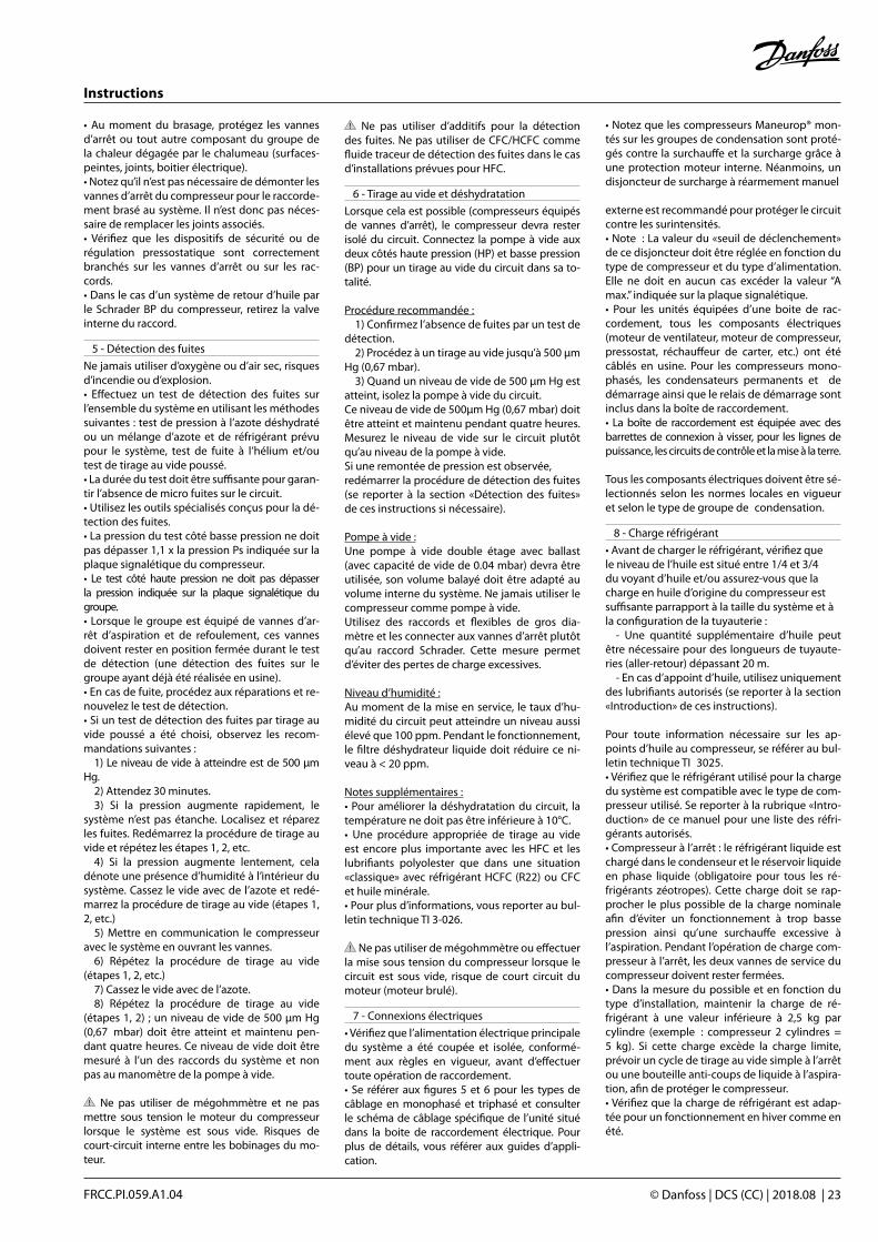
Instructions
© Danfoss | DCS (CC) | 2018.08 | 23FRCC.PI.059.A1.04
• Au moment du brasage, protégez les vannes d’arrêt ou tout autre composant du groupe de la chaleur dégagée par le chalumeau (surfaces-peintes, joints, boitier électrique).• Notez qu’il n’est pas nécessaire de démonter les vannes d’arrêt du compresseur pour le raccorde-ment brasé au système. Il n’est donc pas néces-saire de remplacer les joints associés.• Vérifiez que les dispositifs de sécurité ou de régulation pressostatique sont correctement branchés sur les vannes d’arrêt ou sur les rac-cords.• Dans le cas d’un système de retour d’huile par le Schrader BP du compresseur, retirez la valve interne du raccord.
5 - Détection des fuites
Ne jamais utiliser d’oxygène ou d’air sec, risques d’incendie ou d’explosion.• Effectuez un test de détection des fuites sur l’ensemble du système en utilisant les méthodes suivantes : test de pression à l’azote déshydraté ou un mélange d’azote et de réfrigérant prévu pour le système, test de fuite à l’hélium et/ou test de tirage au vide poussé.• La durée du test doit être suffisante pour garan-tir l’absence de micro fuites sur le circuit.• Utilisez les outils spécialisés conçus pour la dé-tection des fuites.• La pression du test côté basse pression ne doit pas dépasser 1,1 x la pression Ps indiquée sur la plaque signalétique du compresseur.• Le test côté haute pression ne doit pas dépasser la pression indiquée sur la plaque signalétique du groupe.• Lorsque le groupe est équipé de vannes d’ar-rêt d’aspiration et de refoulement, ces vannes doivent rester en position fermée durant le test de détection (une détection des fuites sur le groupe ayant déjà été réalisée en usine).• En cas de fuite, procédez aux réparations et re-nouvelez le test de détection.• Si un test de détection des fuites par tirage au vide poussé a été choisi, observez les recom-mandations suivantes : 1) Le niveau de vide à atteindre est de 500 µm Hg. 2) Attendez 30 minutes. 3) Si la pression augmente rapidement, le système n’est pas étanche. Localisez et réparez les fuites. Redémarrez la procédure de tirage au vide et répétez les étapes 1, 2, etc. 4) Si la pression augmente lentement, cela dénote une présence d’humidité à l’intérieur du système. Cassez le vide avec de l’azote et redé-marrez la procédure de tirage au vide (étapes 1, 2, etc.) 5) Mettre en communication le compresseur avec le système en ouvrant les vannes. 6) Répétez la procédure de tirage au vide (étapes 1, 2, etc.) 7) Cassez le vide avec de l’azote. 8) Répétez la procédure de tirage au vide (étapes 1, 2) ; un niveau de vide de 500 µm Hg (0,67 mbar) doit être atteint et maintenu pen-dant quatre heures. Ce niveau de vide doit être mesuré à l’un des raccords du système et non pas au manomètre de la pompe à vide.
Ne pas utiliser de mégohmmètre et ne pas mettre sous tension le moteur du compresseur lorsque le système est sous vide. Risques de court-circuit interne entre les bobinages du mo-teur.
Ne pas utiliser d’additifs pour la détection des fuites. Ne pas utiliser de CFC/HCFC comme fluide traceur de détection des fuites dans le cas d’installations prévues pour HFC.
6 - Tirage au vide et déshydratation
Lorsque cela est possible (compresseurs équipés de vannes d’arrêt), le compresseur devra rester isolé du circuit. Connectez la pompe à vide aux deux côtés haute pression (HP) et basse pression (BP) pour un tirage au vide du circuit dans sa to-talité.
Procédure recommandée : 1) Confirmez l’absence de fuites par un test de détection. 2) Procédez à un tirage au vide jusqu’à 500 µm Hg (0,67 mbar). 3) Quand un niveau de vide de 500 µm Hg est atteint, isolez la pompe à vide du circuit.Ce niveau de vide de 500µm Hg (0,67 mbar) doit être atteint et maintenu pendant quatre heures. Mesurez le niveau de vide sur le circuit plutôt qu’au niveau de la pompe à vide.Si une remontée de pression est observée,redémarrer la procédure de détection des fuites (se reporter à la section «Détection des fuites» de ces instructions si nécessaire).
Pompe à vide :Une pompe à vide double étage avec ballast (avec capacité de vide de 0.04 mbar) devra être utilisée, son volume balayé doit être adapté au volume interne du système. Ne jamais utiliser le compresseur comme pompe à vide.Utilisez des raccords et flexibles de gros dia-mètre et les connecter aux vannes d’arrêt plutôt qu’au raccord Schrader. Cette mesure permet d’éviter des pertes de charge excessives.
Niveau d’humidité :Au moment de la mise en service, le taux d’hu-midité du circuit peut atteindre un niveau aussi élevé que 100 ppm. Pendant le fonctionnement, le filtre déshydrateur liquide doit réduire ce ni-veau à < 20 ppm.
Notes supplémentaires :• Pour améliorer la déshydratation du circuit, la température ne doit pas être inférieure à 10°C. • Une procédure appropriée de tirage au vide est encore plus importante avec les HFC et les lubrifiants polyolester que dans une situation «classique» avec réfrigérant HCFC (R22) ou CFC et huile minérale.• Pour plus d’informations, vous reporter au bul-letin technique TI 3-026.
Ne pas utiliser de mégohmmètre ou effectuer la mise sous tension du compresseur lorsque le circuit est sous vide, risque de court circuit du moteur (moteur brulé).
7 - Connexions électriques
• Vérifiez que l’alimentation électrique principale du système a été coupée et isolée, conformé-ment aux règles en vigueur, avant d’effectuer toute opération de raccordement.• Se référer aux figures 5 et 6 pour les types de câblage en monophasé et triphasé et consulter le schéma de câblage spécifique de l’unité situé dans la boite de raccordement électrique. Pour plus de détails, vous référer aux guides d’appli-cation.
• Notez que les compresseurs Maneurop® mon-tés sur les groupes de condensation sont proté-gés contre la surchauffe et la surcharge grâce à une protection moteur interne. Néanmoins, un disjoncteur de surcharge à réarmement manuel
externe est recommandé pour protéger le circuit contre les surintensités.• Note : La valeur du «seuil de déclenchement» de ce disjoncteur doit être réglée en fonction du type de compresseur et du type d’alimentation. Elle ne doit en aucun cas excéder la valeur “A max.” indiquée sur la plaque signalétique.• Pour les unités équipées d’une boite de rac-cordement, tous les composants électriques (moteur de ventilateur, moteur de compresseur, pressostat, réchauffeur de carter, etc.) ont été câblés en usine. Pour les compresseurs mono-phasés, les condensateurs permanents et de démarrage ainsi que le relais de démarrage sont inclus dans la boîte de raccordement.• La boîte de raccordement est équipée avec des barrettes de connexion à visser, pour les lignes de puissance, les circuits de contrôle et la mise à la terre.
Tous les composants électriques doivent être sé-lectionnés selon les normes locales en vigueur et selon le type de groupe de condensation.
8 - Charge réfrigérant
• Avant de charger le réfrigérant, vérifiez quele niveau de l’huile est situé entre 1/4 et 3/4du voyant d’huile et/ou assurez-vous que lacharge en huile d’origine du compresseur estsuffisante parrapport à la taille du système et àla configuration de la tuyauterie : - Une quantité supplémentaire d’huile peut être nécessaire pour des longueurs de tuyaute-ries (aller-retour) dépassant 20 m. - En cas d’appoint d’huile, utilisez uniquement des lubrifiants autorisés (se reporter à la section «Introduction» de ces instructions).
Pour toute information nécessaire sur les ap-points d’huile au compresseur, se référer au bul-letin technique TI 3025.• Vérifiez que le réfrigérant utilisé pour la charge du système est compatible avec le type de com-presseur utilisé. Se reporter à la rubrique «Intro-duction» de ce manuel pour une liste des réfri-gérants autorisés.• Compresseur à l’arrêt : le réfrigérant liquide est chargé dans le condenseur et le réservoir liquide en phase liquide (obligatoire pour tous les ré-frigérants zéotropes). Cette charge doit se rap-procher le plus possible de la charge nominale afin d’éviter un fonctionnement à trop basse pression ainsi qu’une surchauffe excessive à l’aspiration. Pendant l’opération de charge com-presseur à l’arrêt, les deux vannes de service du compresseur doivent rester fermées. • Dans la mesure du possible et en fonction du type d’installation, maintenir la charge de ré-frigérant à une valeur inférieure à 2,5 kg par cylindre (exemple : compresseur 2 cylindres = 5 kg). Si cette charge excède la charge limite, prévoir un cycle de tirage au vide simple à l’arrêt ou une bouteille anti-coups de liquide à l’aspira-tion, afin de protéger le compresseur.• Vérifiez que la charge de réfrigérant est adap-tée pour un fonctionnement en hiver comme en été.

Instructions
24 | © Danfoss | DCS (CC) | 2018.08 FRCC.PI.059.A1.04
9 - Vérification avant démarrage
Assurez-vous que toutes les vannes de ser-vice sont en position ouverte avant le démar-rage. Une vanne de refoulement ou d’aspiration fermée pourrait gravement endommager le compresseur et/ou rendre inopérants les dispo-sitifs de sécurité, exposant ainsi le personnel à un risque de blessure.• Vérifiez que tous les organes de sécurité sont en bon état de marche et bien réglés (point de réglage des pressostats et autres vannes ou sou-papes de sécurité, etc.). Veillez à ce que ces dis-positifs soient conformes aux réglementations et normes en vigueur tant au niveau général qu’au niveau local (par exemple : norme européenne EN 378-2:2016).• Le réglage des pressostats haute pression ou des soupapes de sécurité ne doit jamais dé-passer la pression de service maximale d’un quelconque composant du système. Se reporter au guide d’application pour les pressions maxi-mum de sécurité du groupe de condensation.• L’utilisation d’un pressostat de sécurité basse pression est recommandée pour empêcher un fonctionnement sous vide. Réglage minimum recommandé : 1.1 bar (absolu).• Vérifiez que toutes les connexions électriques sont bien serrées et conformes aux réglementa-tions de sécurité en vigueur au niveau local.• Un réchauffeur de carter a été installé en usine sur le compresseur ; il doit être mis sous tension au minimum 12 heures avant la première miseen service et/ou lors du démarrage après une période d’arrêt prolongée.
10 - Mise en service
Ne jamais démarrer le compresseur sous vide ou en l’absence d’une charge de réfrigérant (risque de claquage moteur).• Ne jamais court-circuiter le pressostat BP ou tout autre dispositif de sécurité lors du démar-rage.• Vérifiez la tension d’alimentation et le courant absorbé.• Vérifiez le sens d’orientation des ventilateurs de condenseur (débit d’air vers le compresseur).• Réglage de la surchauffe d’aspiration : la sur-chauffe optimale à l’aspiration du compresseur est de l’ordre de 10K, la surchauffe maximum autorisée se situant à 30K.• Dans tous les cas, les limites d’application du compresseur doivent être respectées. En outre, des valeurs élevées de surchauffe conduisent à des hautes températures de refoulement et font diminuer la capacité du compresseur. La tempé-rature maximale de refoulement est de 130°C : le fonctionnement à une température supérieure peut engendrer la décomposition du réfrigérant.• En régime de fonctionnement établi, contrôlez les vibrations des tuyauteries et tubes capillaires; des vibrations anormales (déplacement de la tuyauterie supérieur à 1.5 mm) nécessitent des ac-tions correctives telles que des supports de tuyau-teries etc.).• Vérifier le retour d’huile au compresseur à l’aide du voyant d’huile. Après une durée de fonction-nement de 2 à 4 heures aux conditions nominales, vérifiez le niveau d’huile et, si nécessaire, réalisez un appoint (voir bulletin technique TI2-025). Si le retour d’huile au compresseur ne s’améliorait pas, des investigations plus approfondies sur la confi-guration des tuyauteries seraient nécessaires.• Vérifiez que la charge de réfrigérant est suffi-sante à l’aide du voyant liquide (si le circuit en
est équipé) et contrôlez que les températures de fonctionnement correspondent aux spécifica-tions du système.• Si besoin est, un complément de charge peut être effectué en phase liquide, côté basse pres-sion. Le liquide doit être injecté aussi loin que possible du compresseur en étranglant le débit afin d’éviter tout risque de coup de liquide. Le compresseur doit être en marche pendant ce processus.
Evitez une charge excessive de réfrigérant dans le système.
11 - Dépannage
• Problème de démarrage du compresseur : vé-rifiez l’alimentation électrique du compresseur et contrôlez les connexions de puissance. Vérifiez les connexions en amont ainsi que les condensateurs pour les modèles monophasés. Si ces vérifications ne montrent aucune anomalie, testez la continuité des bobinages du moteur avec un ohmmètre (cou-pure de la protection interne).Note : lorsque la protection interne du moteur se déclenche, plusieurs heures peuvent être néces-saires à son réarmement et au redémarrage du compresseur.• Le compresseur ne pompe pas : contrôlez que les vannes/soupapes de sécurité du système ne sont pas ouvertes. Vérifiez également que toutes les électro-vannes sont en position normale. Si la soupape de sécurité interne est ouverte, l’en-veloppe du compresseur sera chaude et le com-presseur déclenchera sur la protection moteur. Si cela se produit, le réarmement peut prendre deux à trois heures.• Bruit de fonctionnement anormal : vérifiez l’absence de retour de liquide au compresseur en mesurant la surchauffe des gaz d’aspiration et la température de refoulement du compres-seur. La température du carter d’huile doit se situer au moins 10K au-dessus de la température d’aspiration saturée en régime de fonctionne-ment permanent. Vérifiez que les ventilateurs tournent librement et sans vibration.• Le pressostat de sécurité haute pression se déclenche : contrôlez le condenseur (propreté, fonctionnement du ventilateur, débit d’eau, ré-glage de la vanne pressostatique, filtre, etc.). Si ces vérifications se révèlent négatives, l’origine du problème peut être soit une surcharge de ré-frigérant soit la présence d’incondensables dans le circuit (air).• Le pressostat de sécurité basse pression se déclenche : contrôlez le fonctionnement de l’évaporateur (propreté de la batterie, fonc-tionnement du ventilateur, débit d’eau, encras-sement des filtres, etc.), le débit du réfrigérant liquide et les pertes de charge (vanne solénoïde, filtre déshydrateur, détendeur, etc.), la charge de réfrigérant.• Une charge de réfrigérant trop faible : l’in-dication d’une charge de réfrigérant appropriée est donnée par l’état du voyant liquide, le delta T au condenseur par rapport aux tables du ré-frigérant (pression-température), la surchauffe et le sous refroidissement, etc. (si un appoint de charge s’avère nécessaire, se reporter au cha-pitre «Charge réfrigérant»).• Fonctionnement en court cycle : cinq minutes minimum entre deux démarrages du compres-seur. DCC recommande deux minutes au moins de fonctionnement après chaque démarrage, et entre chaque arrêt et démarrage, trois minutes
d’arrêt. Le fonctionnement en pump down peut seul autoriser des temps de fonctionnement plus courts, jusqu’à obtention de la pression recher-chée, ou lorsque les organes de sécurité imposent un arrêt.
12 - Maintenance
• Des opérations d’entretien préventif du sys-tème ou de l’installation permettent d’éviter des problèmes compresseur dont la cause provien-drait d’un dysfonctionnement du système. Les vérifications suivantes de maintenance préven-tive périodique sont vivement conseillées : - Contrôler les conditions de fonctionnement du compresseur (température d’évaporation, température de condensation, température de refoulement de compresseur, la différence de température sur les échangeurs de chaleur, sur-chauffe, sous-refroidissement). Ces paramètres de fonctionnement doivent toujours respecter les limites de la plage d’utilisation du compres-seur. - Vérifiez que les dispositifs de sécurité sont tous opérationnels et correctement réglés. - Contrôlez le niveau d’huile compresseur et son aspect. En cas de changement de couleur, vérifiez sa qualité. Ceci peut inclure un test d’aci-dité, un contrôle d’humidité, une analyse spec-trométrique, etc. - Vérifiez l’étanchéité du circuit frigorifique. - Vérifiez le fonctionnement des échangeurs de chaleur et procédez à leur nettoyage, si né-cessaire. - Contrôlez le bon fonctionnement des venti-lateurs (absence de vibrations), contrôlez le cou-rant absorbé par le moteur du compresseur ainsi que l’équilibre de tension entre phases. - Remarque 1 : le condenseur doit faire l’objet d’au moins une vérification de l’encrassement par an et doit être nettoyé si cela s’avère néces-saire. L’accès à la face interne du condenseur se fait par le panneau du ventilateur.La poussière a tendance à se déposer à la sur-face et non à l’intérieur des serpentins à micro-canaux, ce qui rend ces derniers plus faciles à nettoyer que les serpentins à tubes à ailettes. - Changez le filtre déshydrateur liquide, si né-cessaire. - Contrôlez le serrage de toutes les connexions électriques. - Assurez-vous de la propreté et du bon état de marche du groupe de condensation ; vérifiez l’absence de rouille ou de corrosion sur tous les composants sous pression et sur les connexions électriques. - Assurez-vous que la charge de réfrigérant est adaptée à un fonctionnement toute saison, été comme hiver.• Vérifiez que les inspections périodiques dufonctionnement exigées par les réglementa-tions locales ont été effectuées. - Remarque 2 : retirez la poussière, les feuilles, les fibres, etc. qui se trouvent à surface à l’aide d’un aspirateur équipé d’une brosse ou de tout autre embout souple. Vous pouvez également souffler de l’air comprimé depuis l’intérieur de l’échangeur et évacuer la saleté à l’aide d’une brosse à poils souples. N’utilisez pas de brosse métallique. Veillez à ne pas endommager ou rayer l’échangeur avec le tube de l’aspirateur ou l’embout du compresseur à air.

Instructions
© Danfoss | DCS (CC) | 2018.08 | 25FRCC.PI.059.A1.04
13 - Remplacement
S’assurer de l’absence de réfrigérant sous pression dans le circuit lors de la dépose d’un quelconque composant, de la découpe de tuyauteries ou autres travaux de perçage ou de démontage d’organes sous pression.
Ne pas libérer le réfrigérant de l’installation à l’atmosphère. Utiliser des techniques et du ma-tériel de récupération approuvés pour un stoc-kage respectant la législation en vigueur.
La présence de vapeur de réfrigérant dans un local fermé peut entraîner l’asphyxie. Une ven-tilation suffisante est obligatoire lors de toute intervention sur le système.
Tout remplacement d’un composant du groupe de condensation doit s’effectuer selon les réglementations locales en vigueur.• Assurez-vous que l’alimentation électrique principale a été coupée.• Avant remplacement, déterminez la cause de la panne et effectuez les réparations nécessaires. Si cette analyse et ces réparations ne sont pas réalisées, des pannes répétitives peuvent se pro-duire. Notez qu’un test d’acidité d’huile s’avère toujours utile en tant que diagnostique lors d’un remplacement de compresseur.• Vérifiez que le composant de remplacement présente les mêmes caractéristiques électriques et de puissance frigorifique que l’original.• Lorsque des modifications de tuyauterie sont nécessaires, veuillez vous référer au chapitre «Mesures de sécurité avant montage».• Pour de plus amples renseignements sur les procédures de remplacement, se reporter aux chapitres précédent.Note : En cas de panne moteur du compresseur, vidangez et nettoyez le circuit avant remplace-
ment du compresseur afin d’éliminer les acides et tout autre contaminant. D’une manière systé-matique, installez un nouveau filtre déshydrateur de ligne liquide. Au préalable (si nécessaire), faire fonctionner le système au minimum 2 heures avec des cartouches de filtre anti-acide (dans les cas de contamination sévère, l’utilisation de filtre d’aspi-ration peut également s’avérer nécessaire). Après un fonctionnement d’environ 2 semaines, vérifiez le niveau d’acidité de l’huile. Si ce test est positif, vidangez et remplacez l’huile, remplacez égale-ment les cartouches du filtre déshydrateur par des cartouches anti-acide ainsi que les cartouches du filtre d’aspiration installé précédemment. Répétez ces remplacements d’huile et cartouches de filtre jusqu’à ce que le système soit propre et exempt de tout acide. Quand il n’y a plus aucune trace d’acide, remplacez les cartouches anti-acides par le modèle standard et retirez la cartouche du filtre d’aspiration.
14 - Conseils aux utilisateurs
Veillez à ce que toutes les opérations de service et de maintenance soient effectuées unique-ment par un personnel qualifié.
Les températures de surface, tuyauteries et compresseur peuvent, dans certains cas, dé-passer 100°C (212°F) et provoquer des brûlures corporelles. Une prudence particulière s’im-pose donc lors des travaux sur le groupe et ses tuyauteries. D’autre part, lorsque le compres-seur est en fonctionnement, la température de ces surfaces peut également être extrêmement froide(jusqu’à -45°C / -49°F), exposant ainsi le personnel à un risque de brûlures par le froid.
La pression interne du compresseur peut atteindre des niveaux dangereusement élevés (par exemple : dysfonctionnement, incendie)
pouvant occasionner des blessures au person-nel en cas de dégagement soudain de pression ; en conséquence, ne jamais percer, souder ou couper le réservoir liquide, l’enveloppe du com-presseur et ses tuyauteries (le dégagemet de réfrigérant liquide peut entraîner sur une peau découverte des gelures instantanées).
Bien que les ventilateurs soient équipés de grilles de protection, il est conseillé de ne pas ef-fectuer de travaux sur le condenseur en fonction-nement.La garantie du produit peut être invalidée dans les circonstances suivantes :• modifications de l’unité (sauf approbation ex-presse par Danfoss Commercial Compressors), absence de plaque signalétique, composants abîmés ou cassés, traces de choc, etc.,• compresseur découpé par l’utilisateur ou retour-né ouvert au constructeur (c’est-à-dire avec les rac-cords de refoulement ou d’aspiration non obturés),• présence de rouille ou d’eau à l’intérieur du cir-cuit du groupe de condensation,• adjonction de fluide de détection des fuites dans le lubrifiant du compresseur,• utilisation d’un réfrigérant ou d’un lubrifiant non-approuvé par Danfoss Commercial Com-pressors,• non-observation des instructions spécifiques d’installation, d’application ou de maintenance,• utilisation du groupe de condensation pour des applications mobiles (bateaux, trains, ca-mions, etc.) ou en atmosphères déflagrantes.La date de fabrication du groupe de condensa-tion est indiquée sur la plaque signalétique. Lesinformations relatives au modèle et numéro de série du groupe doivent toujours être fournies pour toute réclamation concernant ce produit.
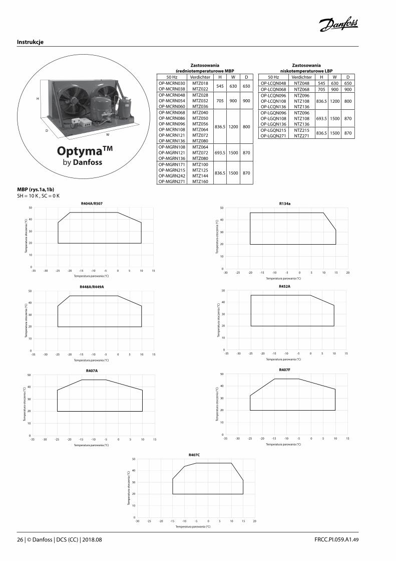
Instrukcje
26 | © Danfoss | DCS (CC) | 2018.08 FRCC.PI.059.A1.49
Zastosowania średniotemperaturowe MBP
50 Hz Verdichter H W DOP-MCRN030OP-MCRN038
MTZ018MTZ022
545 630 650
OP-MCRN048OP-MCRN054OP-MCRN060
MTZ028MTZ032MTZ036
705 900 900
OP-MCRN068OP-MCRN086OP-MCRN096OP-MCRN108OP-MCRN121OP-MCRN136
MTZ040MTZ050MTZ056MTZ064MTZ072MTZ080
836.5 1200 800
OP-MGRN108OP-MGRN121OP-MGRN136
MTZ064MTZ072MTZ080
693.5 1500 870
OP-MGRN171OP-MGRN215OP-MGRN242OP-MGRN271
MTZ100MTZ125MTZ144MTZ160
836.5 1500 870
Zastosowania niskotemperaturowe LBP
50 Hz Verdichter H W DOP-LCQN048 NTZ048 545 630 650OP-LCQN068 NTZ068 705 900 900OP-LCQN096OP-LCQN108OP-LCQN136
NTZ096 NTZ108NTZ136
836.5 1200 800
OP-LGQN096OP-LGQN108OP-LGQN136
NTZ096NTZ108NTZ136
693.5 1500 870
OP-LGQN215OP-LGQN271
NTZ215NTZ271
836.5 1500 870
-350
10
20
30
40
50
-30 -25 -20 -15 -10 -5 0 5 10 15
Evaporating Temperature (°C)
R404A/R507
Am
bien
t Tem
pera
ture
(°C)
-350
10
20
30
40
50
-30 -25 -20 -15 -10 -5 0 5 10 15
Evaporating Temperature (°C)
R448A/R449A
Am
bien
t Tem
pera
ture
(°C)
-350
10
20
30
40
50
-30 -25 -20 -15 -10 -5 0 5 10 15
Evaporating Temperature (°C)
R407A
Am
bien
t Tem
pera
ture
(°C)
0
10
20
30
40
50
-30 -25 -20 -15 -10 -5 0 5 10 15 20
Evaporating Temperature (°C)
R407C
Am
bien
t Tem
pera
ture
(°C)
-350
10
20
30
40
50
-30 -25 -20 -15 -10 -5 0 5 10 15
Evaporating Temperature (°C)
R452A
Am
bien
t Tem
pera
ture
(°C)
-350
10
20
30
40
50
-30 -25 -20 -15 -10 -5 0 5 10 15
Evaporating Temperature (°C)
R407F
Am
bien
t Tem
pera
ture
(°C)
0
10
20
30
40
50
-30 -25 -20 -15 -10 -5 0 5 10 15 20
Evaporating Temperature (°C)
R134a
Am
bien
t Tem
pera
ture
(°C)
SH = 10 K , SC = 0 KMBP (rys.1a,1b)
Tem
per
atur
a ot
ocze
nia
(°C
)
Temperatura parowania (°C)Temperatura parowania (°C)
Tem
per
atur
a ot
ocze
nia
(°C
)
Temperatura parowania (°C)
Tem
per
atur
a ot
ocze
nia
(°C
)
Temperatura parowania (°C)
Tem
per
atur
a ot
ocze
nia
(°C
)
Temperatura parowania (°C)
Tem
per
atur
a ot
ocze
nia
(°C
)
Temperatura parowania (°C)
Tem
per
atur
a ot
ocze
nia
(°C
)
Temperatura parowania (°C)
Tem
per
atur
a ot
ocze
nia
(°C
)
OptymaTM
by Danfoss
WD
H

Instrukcje
© Danfoss | DCS (CC) | 2018.08 | 27FRCC.PI.059.A1.49
8 do 12 m/sprzy minimalnejwydajnosci
8 do 12 m/sprzy maksymalnejwydajnoscirys.3
Tlumik wibracji
rys.4
rys.2
1 x coil height Min. clearance: 2 x unit length
-450
10
20
30
40
50
-40 -35 -30 -25 -20 -15 -10 -5 0 5
Evaporating Temperature (°C)
R404A/R507
Am
bien
t Tem
pera
ture
(°C)
-450
10
20
30
40
50
-40 -35 -30 -25 -20 -15 -10 -5 0 5
Evaporating Temperature (°C)
R452A
Am
bien
t Tem
pera
ture
(°C)
SH = 10 K , SC = 0 KLBP (rys.1a,1b)
Tem
per
atur
a ot
ocze
nia
(°C
)
Temperatura parowania (°C)
Tem
per
atur
a ot
ocze
nia
(°C
)
Temperatura parowania (°C)
Minimalny odstęp: 2 x szerokość agregatu1 x wysokość wymiennika
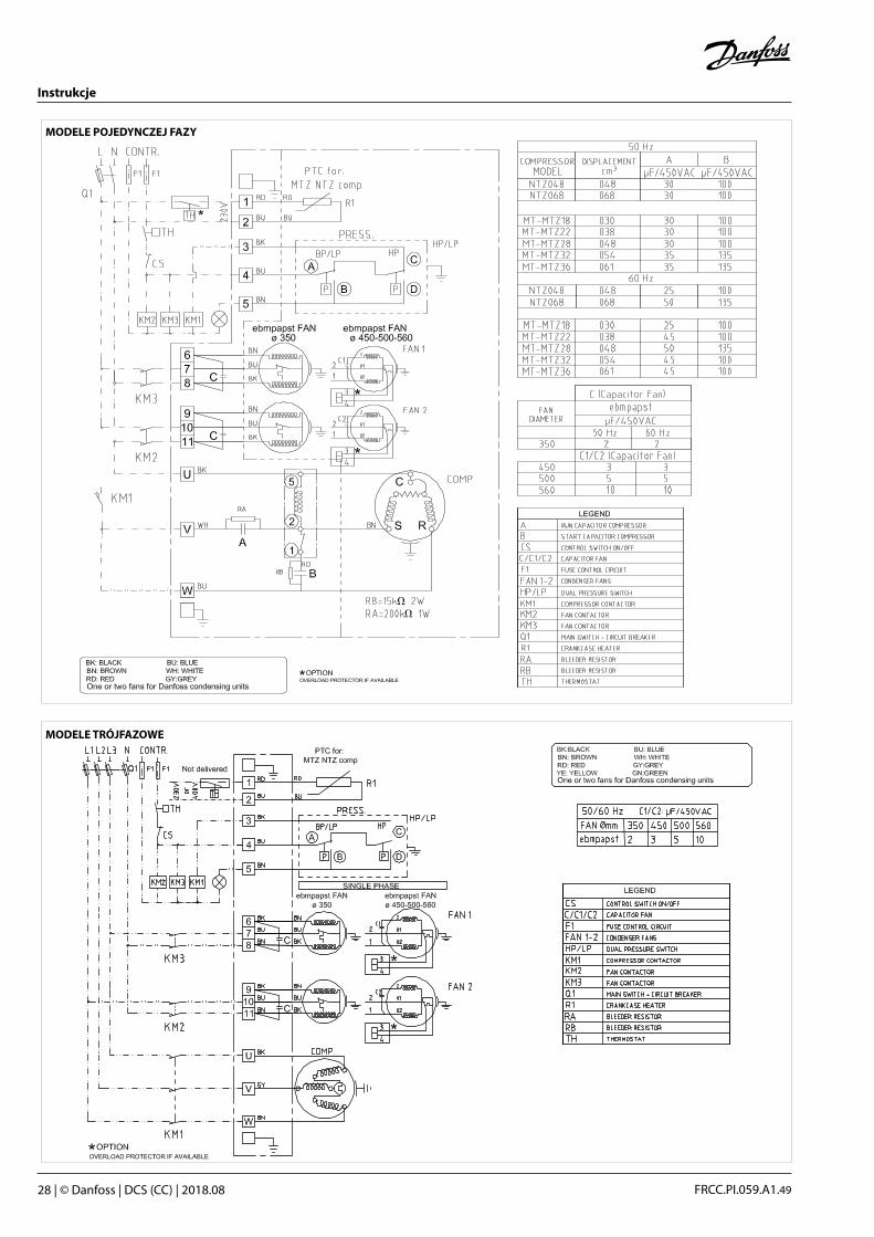
Instrukcje
28 | © Danfoss | DCS (CC) | 2018.08 FRCC.PI.059.A1.49
MODELE POJEDYNCZEJ FAZY
MODELE TRÓJFAZOWE

Instrukcje
© Danfoss | DCS (CC) | 2018.08 | 29FRCC.PI.059.A1.49
KP 15 060-1154, 060-1220, 060-1261, 060-1263, 060-1283
LP-man LP-auto LP-auto LP-manHP-man HP-man HP-auto HP-auto
Niskie ciśnienie LP, odblokowanie ręczneNiskie ciśnienie LP, odblokowanie automatyczne
AC1 16 A DC 11LR 112A AC3 16 A 400 V � 12 W
AC11 10 A 220 V �
-1 bar (Pe)(30in.Hg)
KP 15, 15A, 17W, 17B
KP 17B 060-539366, 060-539466
LP-auto LP-autoHP-man HP-auto
Ciśnieniezałączania
Różnica Stała różnica
Ciśnienie wyłączania
Sprawdzianmanualny
Ciśnieniezałączania
Tightening torque 20 lb.in Use copper wire only
Ciśnieniewyłączania
Reset manuel
SPDT + LP niskie ciśnienie
LP LP HP
Wysokie ciśnienie HP
LP + HP niskie i wysokie ciśnienie
Ustawieniafabryczne
Reset manuel
Odblokowanie przełączalne
Odblokowanie przełączalne
Stała różnica
Ciśnieniewyłączania
Ciśnieniezałączania
HP
LP Różnica
LP
do modeli R404A
HP (bar)
MBP 28 8
LBP 28 3
LP (bar)
Ustawienie fabryczne

Instrukcje
30 | © Danfoss | DCS (CC) | 2018.08 FRCC.PI.059.A1.49
Spis treści:
1 - Wprowadzenie. 2 - Transport, magazynowanie. 3 - Środki bezpieczeństwa podjęte
przed montażem urządzenia. 4 - Montaż. 5 - Nieszczelności i sposoby ichwy-
krywania. 6 - Usuwanie wilgoci z instalacji. 7 - Zasilanie. 8 - Napełnianie instalacji czynnikiem
chłodniczym. 9 - Kontrola urządzenia. 10 - Uruchomienie. 11 - Wykrywanie i usuwanie usterek. 12 - Konserwacja. 13 - Wymiana części. 14 - Wskazówki dla użytkownika.
1 - Wprowadzenie
Poniższe wskazówki dotyczą agregatów skraplający-ch Optyma™ Blue przeznaczonych do zastosowań chłodniczych i mają na celu przedstawienie nieo-dzownych informacji dotyczących bezpieczeństwa i właściwej obsługi tego rodzaju urządzeń.Wszystkie informacje przedstawione są w sposób ogólny dla tego typu urządzeń; dlate-go pewne szczegóły mogą nie odnosić się do zakupionego agregatu. Poniższą instrukcję jak również wszystkie wskazówki dotyczące agre-gatów skraplających Bluestar należy przechowy-wać w dostępnym miejscu. • Opis wyposażenia: agregaty skraplające są produkowane w różnych wykonaniach. Składają się one ze sprężarki i skraplacza, chłodzonego za pomocą wentylatora i są zamontowane na podstawie. Dodatkowo agregaty mogą być wy-posażone w zbiornik cieczy, presostat, zawory serwisowe i skrzynkę przyłączeniową.• Stosowane czynniki chłodnicze: - agregaty typu MCRN i MGRN (z zamon-towanymi sprężarkami Maneurop® MTZ) mogą być użyte z czynnikami R404A, R507, R134a, R407C, R407A, R452A R448A, R449A.. - agregaty typu LCQN i LGQN (z zamon-towanymi sprężarkami Maneurop® NTZ) mogą być użyte z czynnikami R404A, R452A i R507.• Sprężarki Maneurop są standardowo na-pełnione olejem: - seria MTZ: estrowym (typ 175PZ), - seria NTZ: estrowym (typ 175Z).Zabrania się mieszania różnych typów oleju.• Agregaty skraplające mogą być używane tylko i wyłącznie do celów zgodnych z ich przeznacze-niem i w warunkach zgodnych z ich dopuszczal-nym zakresem pracy (patrz rys.1a,1b).
Agregaty skraplające są standardowo wy-pełnione azotem pod ciśnieniem od 1 do 2 barów i w związku z tym nie mogą być bezpośre-dnio podłączone do instalacji. Szczegółowe ws-kazówki są przedstawione w punkcie «MON-TAŻ».
Agregaty skraplające nie są przeznaczone do zastosowań w transporcie ani w strefach zagrożonych wybuchem. Jakiekolwiek użycie czynników łatwopalnych (np. węglowodorowy-ch) lub powietrza jest surowo zabronione.• W każdym przypadku muszą być spełnione wy-mogi określone w normie EN 378-2:2016 lub inne równoważne.
Próby ciśnieniowe powinny być przeprowadzane przez wykwalifikowane osoby. Należy uwzględnić potencjalne zagrożenie wynikające z występujący-
ch ciśnień i przestrzegać ich maksymalnych wartoś-ci. Wartości tych ciśnień są zapisane na tabliczkach znamionowych sprężarek lub w instrukcji obsługi.
Modernizacje oraz dokonywanie przeróbek sprężarki lub zbiornika cieczy (jak np. «lu-towanie twarde» płaszcza) nie zaaprobowane przez stronę odpowiedzialną za zapewnienie zgodności urządzenia z wymaganiami bez-pieczeństwa może skutkować utratą prawa do użytkowania urządzenia.
2 - Transport, magazynowanie
• Agregaty skraplające muszą być usytuowane w pozycji pionowej (maksymalne odchylenie od pionu wynosi 15°). • Należy zwrócić uwagę na to, aby podczas trans-portu agregatów skraplających wykonywać ws-zelkie czynności z należytą uwagą, a w szcze-gólności by nie poddawać urządzeń różnego rodzaju wstrząsom. Należy używać odpowiednich i bezpiecznych podnośników podczas przewożenia i rozpako-wywania.Należy zwrócić uwagę na przednią stronę skraplacza, która jest oznakowana na opakowa-niu.• Wszelkie uszkodzenia opakowania czy też produktu zauważone przy dostawie powinny być niezwłocznie zgłoszone przewoz’nikowi. Te same zalecenia odnoszą się do przypadku, gdy wykryte zostaną uchybienia podczas transportu produktu do użytkownika.• Należy zapoznać się z instrukcją bez-pieczeństwa opisaną na opakowaniu urządze-nia.• Agregaty skraplające nie mogą być przechowy-wane w temperaturze poniżej -35°C ani powyżej +50°C.• Należy upewnić się czy urządzenie i jego opa-kowanie nie jest narażone na bezpośrednie działanie deszczu, czynników łatwopalnych oraz czynników powodujących korozję.
3 - Środki bezpieczeństwa podjęte przed mon-tażem urządzenia
• Wszystkie podłączenia, obsługa i serwisowa-nie urządzenia muszą być wykonywane przez wykwalifikowane osoby, zgodnie z przyjętymi zasadami i procedurami bezpieczeństwa.• Agregat skraplający musi być ulokowany w dobrze wentylowanym miejscu; przepływ powietrza przez agregat nie może być ogra-niczony w jakikolwiek sposób (patrz rys.2). Należy upewnić się, że temperatura otoczenia podczas postoju urządzenia nigdy nie przekroc-zy 50°C.• W przypadku montażu agregatu na zewnątrz budynków należy użyć obudowę agregatu skraplającego firmy DANFOSS MANEUROP lub zapewnić ochronę przed czynnikami atmosfery-cznymi w inny sposób.• Agregat skraplający może być zamontowany na poziomej (maksymalne nachylenie 3°) powie-rzchni. • Sprawdzić, czy posiadany agregat skraplający jest odpowiedni pod względem parametrów i danych technicznych (wydajność, użyty czynnik chłodniczy itd.). • Sprawdzić, czy zasilanie (napięcie, częstot-liwość) jest zgodne z nominalnym napięciem zasilania użytych sprężarek i wentylatorów skraplacza (patrz tabliczka znamionowa agre-gatu).
• Upewnić się, że osprzęt do napełniania instalacji czynnikiem chłodniczym, pompy próżniowe itd. przeznaczone do instalacji chłod-niczych napełnianych HFC są użytkowane tylko i wyłącznie do tych czynników i nie były nigdy wcześniej wykorzystywane w instalacjach chło-dniczych napełnionych czynnikami z grup CFC i HCFC.• Rurociągi powinny być wykonywane tyl-ko z czystych i osuszonych rur miedzianych przeznaczonych do zastosowań chłodniczych, a połączenia lutowane przy użyciu lutu z do-datkiem srebra. • Wszystkie elementy powinny być sprawdzone przed ich zamontowaniem. Należy upewnić się czy są dobrane właściwie, czyste i osuszone. Sprawdzić prawidłowość wykonania rurociągów ssawnych: Poziome odcinki powinny być pochy-lone w dół, w kierunku sprężarki.Prędkość par czynnika na ssaniu powinna być odpowiednio wysoka do zapewnienia dosta-tecznej ilości powracającego oleju. Prędkość ta powinna wynosić od 8 do 12 m/s dla przewo-dów pionowych. W przewodach poziomych, prędkość ta może wynosić ok. 4 m/s. Może być konieczne zastosowanie pułapek olejowych i podwójnych pionów. W przypadku różnic wyso-kości większych niż 4 m, powinno się stosować dodatkowe pułapki olejowe (patrz rys. 3.). Aby zminimalizować przegrzanie par czynnika chło-dniczego należy izolować przewody ssawne.• Rurociągi przyłączone do sprężarki powinny być tak zaprojektowane by zapewniły swobod-ne drgania sprężarki w trzech płaszczyznach z możliwie małym przenoszeniem drgań na nsta-lację. Sposób wykonania rurociągów powinien uniemożliwić migrację czynnika do sprężarki i jego spływ do karteru.
Podczas instalowania zbiornika cieczy lub in-nego naczynia ciśnieniowego, należy upewnić się, że w.w. elementy spełniają wymogi eu-ropejskiej dyrektywy wysokociśnieniowej (PED 2014/68/EU).
Upewnić się, że instalacja chłodnicza jest wyposażona w zabezpieczenia przed wzros-tem ciśnienia (np. presostat, upustowy zawór bezpieczeństwa), które zapobiegają eksplozji zbiorników ciśnieniowych.• Podczas projektowania, montażu oraz eksploa-tacji instalacji chłodniczej muszą być spełnione wszystkie przepisy i standardy bezpieczeństwa np norma EN 378-2:2016.
4 - Montaż
Możliwość penetracji powietrza atmosfery-cznego do wnętrza agregatu podczas montażu powinna być ograniczona do minimum. Agre-gat skraplający jest wyposażony w miedziane króćce (ssawny i cieczowy) z zamontowanymi zaworami odcinającymi, dzięki czemu możliwy jest montaż agregatu w sposób uniemożliwiają-cy dostanie się powietrza i pary wodnej do jego wnętrza. Otwarcie zaworów odcinających przed wykona-niem połączeń może spowodować zawilgocenie oleju sprężarki.• Blok cichy należy zainstalować pod ramą podstawy agregatu skraplającego tak, jak to pokazano na rys. 4, aby zapobiec zakłóceniom wibracyjnym pochodzącym z innych urządzeń i maszyn oraz ograniczyć przenoszenie drgań na konstrukcję nośną.
Instrukcje
© Danfoss | DCS (CC) | 2018.08 | 31FRCC.PI.059.A1.49
Przed otwarciem zaworów serwisowych sprężarki należy obowiązkowo podłączyć wężyk serwisowy 1/4” do zaworu Schradera w obu-dowie sprężarki w celu stopniowego zreduko-wania ciśnienie azotu.
• Upewnić się, że żadne fragmenty materiału nie dostały się do wnętrza rurociągów podczas przy-cinania rur. Ponadto, niedopuszczalne jest wierce-nie otworów w rurociągach już zmontowanych. • Należy unikać połączeń skręcanych (kieli-chowych). Połączenia lutowane powinny być wykonywane ze szczególną starannością. Podc-zas lutowania należy zapewnić przepływ azotu wewnątrz rurociągu, zapobiegający powstawa-niu tlenków na wewnętrznych ściankach rur. Lut powinien zawierać minimum 5% srebra.• Podczas lutowania należy zabezpieczyć zawo-ry oraz inne elementy agregatu (powierzchnie malowane, uszczelki itd.) przed uszkodzeniami spowodowanymi przegrzaniem.• Demontaż zaworów odcinających podczas po-dłączenia sprężarki do układu nie jest konieczny, w związku z tym nie ma potrzeby wymiany ws-półpracujących uszczelek.• Upewnić się czy są wykonane połączenia niezbęd-nych urządzeń kontrolno-zabezpieczających z zawo-rami odcinającymi sprężarki i innym osprzętem.• W przypadku powrotu oleju przez króciec zaworu Schrader’a do obudowy sprężarki, sprawdz’ czy zawór wewnętrzny jest zdemon-towany.
5 - Nieszczelności i sposoby ich wykrywania
W związku z ryzykiem zapłonu lub możliwością wybuchu nigdy nie używaj tlenu lub suchego powietrza do napełniania instalacji.• Należy przeprowadzać próbę szczelności po całkowitym zmontowaniu układu w jeden z po-niżej przedstawionych sposobów: - próba ciśnieniowa z użyciem suchego azotu, - napełnienie mieszaniną azotu i czynnika chłodniczego, - próba szczelności z użyciem helu i/lub test wysokopróżniowy.• Próba powinna trwać na tyle długo, aby wyeli-minować nawet niewielkie nieszczelności.• Należy używać odpowiednich przyrządów, przeznaczonych do wykrywania nieszczelności.• Ciśnienie próbne na stronie ssawnej nie może przekraczać wartości wynoszącej 1,1 x Ps, gdzie Ps jest ciśnieniem określonym na tabliczce zna-mionowej sprężarki.• Ciśnienie próbne na stronie tłocznej nie może przekraczać wartości podanej na tabliczce zna-mionowej agregatu skraplającego.• W przypadku, gdy agregat jest wyposażony w zawory odcinające na ssaniu i tłoczeniu, zawory te powinny być zamknięte podczas przeprowadza-nia próby szczelności (próba szczelności agregatu skraplającego jest przeprowadzana u Wytwórcy).• W przypadku wykrycia nieszczelności przystąpić do usuwania przyczyn występowania nieszczel-ności, a po ich usunięciu powtórzyć próbę.• W przypadku testu wysokopróżniowego należy: 1) obniżyć ciśnienie w obiegu chłodniczym pompą próżniową do wartości 500 µm słupa Hg, (przy zamkniętych zaworach odcinających na sprężarce). 2) odczekać 30 min. 3) w przypadku gwałtownego wzrostu ciśnie-nia mamy do czynienia z nieszczelnością insta-lacji, należy zlokalizować przeciek i usunąć go,
następnie ponowić próbę zgodnie z procedurą tj. pkt 1 i 2. 4) w przypadku powolnego wzrostu ciśnienia mamy do czynienia z zawilgoce-niem układu, należy wówczas przerwać próbę, wypełnić układ suchym azotem i ponowić zgodnie z procedurą tj. pkt 1 i 2. 5) podłączyć sprężarkę do układu poprzez otwarcie zaworów odcinających sprężarki. 6) powtórzyć kroki 1 i 2 (przy otwartych zawo-rach odcinających na sprężarce). 7) wypełnić instalację suchym azotem. 8) powtórzyć procedurę zgodnie z pkt 1 i 2 (przy otwartych zaworach odcinających na sprężarce), aż do osiągnięcia próżni o wartoś-ci 500 µm Hg (ok. 0,67 mbar). Ciśnienie takie powinno być utrzymane przez ok. 4 godziny, a jego wartość powinna być mierzona w instalacji chłodniczej, a nie odczytywana ze wskaz’ nika pompy próżniowej.
Nie wolno używać megaomomierza ani po-dawać napięcia na uzwojenia silnika sprężarki podczas występowania próżni, ze względu na niebezpieczeństwo uszkodzenia (przepalenia uzwojeń) silnika sprężarki.
Nie należy używać środków barwiących do wykrywania nieszczelności, ani używać po-chodnych chloroflurowęglowodorów podczas przeprowadzania próby szczelności układu projektowanego do napełnienia czynnikiem z grupy HFC.
6 - Usuwanie wilgoci z instalacji
W każdym przypadku, kiedy to możliwe (jeżeli zawory odcinające wchodzą w skład instalacji) agregat skraplający musi być izolowany od układu. Istotne jest również podłączenie pompy próżniowej po obydwu stronach tj. wysokie-go i niskiego ciśnienia, aby odessać wilgoć z zamkniętych przestrzeni układu chłodniczego.Właściwe postępowanie: 1) po zakończonej pozytywnie próbie szczel-ności, 2) obniżyć ciśnienie w instalacji do 500 µm Hg, 3) po osiągnięciu w.w. ciśnienia, odizolować układ od pompy próżniowej, 4) ciśnienie 500 µm Hg powinno być utrzymane przez ok. 4 godziny, a wartość ciśnienia powinna być mierzona w instalacji chłodniczej, a nie odc-zytywana ze wskażnika pompy próżniowej, 5) jeżeli ciśnienie rośnie, powtórzyć próbę szc-zelności (patrz pkt 5).Pompa próżniowa:Do prób powinno się używać dwustopniowej pompy próżniowej z balastowym zaworem ga-zowym (próżnia stała o ciśnieniu 0,04 mbar), jej wydajność powinna być odpowiednia do objętości układu. Nigdy nie używaj sprężar-ki jako pompy próżniowej. Zaleca się używa-nie połączeń o dużych średnicach do króćców zaworów odcinających, co pozwala uniknąć nadmiernych strat ciśnienia. Należy unikać połączeń poprzez zawór Schradera.Zawartość wilgoci:Przed uruchomieniem instalacji dopuszczalna zawartość wilgoci powinna wynosić nie więcej niż 100 ppm. Podczas pracy odwadniacz zamon-towany w rurociągu cieczowym powinien zredu-kować tę wartośc do nie więcej niż 20 ppm.Dodatkowe informacje:• W celu przyspieszenia usunięcia wilgoci z ins-talacji, należy utrzymywać temperaturę układu chłodniczego powyżej 10°C. • Właściwe próżniowanie instalacji powinno
być wykonywane szczególnie starannie w pr-zypadku instalacji wypełnionej HFC i sprężarki smarowanej olejem estrowym w porównaniu z procedurą stosowaną w przypadku czynników z grupy CFC i HCFC i olejów mineralnych.• Szczegółowe informacje można znależć winstrukcji TI 3-026.
Nie należy używać megaomomierza ani po-dawać napięcia na uzwojenia silnika sprężarki podczas występowania próżni, ze względu na możliwość uszkodzenia (przepalenia uzwojeń) silnika sprężarki.
7 - Podłączenie zasilania
• Przed jakimikolwiek czynnościami związanymi z podłączeniem zasilania upewnij się, że główne z’ródło zasilania elektrycznego jest odłączone i izolowane, zgodnie z odpowiednimi przepisami.• Zapoznać się z rys. 5 i 6 - przedstawiającymi ty-powe schematy połączeń elektrycznych oraz przeanalizować schemat połączeń właściwy dla agregatu znajdujący się na wewnętrzne stronie pokrywy skrzynki przyłączeniowej. Szczegółowe informacje są podane w karcie katalogowej agre-gatów (Blue Star Condensing Units. Dobór i zasto-sowanie).• Sprężarki Maneurop® znajdujące się w agrega-tach skraplających są standardowo wyposażone w wewnętrzne zabezpieczenie silnika zapobie-gające przegrzaniu się i przeciążeniu. Zalecane jest jednakże użycie zewnętrznego, przekażnika nadmiarowo-prądowego z ręcznym odblokowa-niem w celu ochrony obwodu zasilania przed zbyt wysokim prądem pobieranym przez silnik.• Nastawa wartości prądu wyzwalającego zad-ziałanie w.w. przekaz’nika powinna wynikać z parametrów przewodu zasilającego i nie może przekroczyć maksymalnej wartości prądu A max wybitej na tabliczce znamionowej.• W przypadku agregatów skraplających wypo-sażonych w skrzynkę przyłączeniową wszystkie połączenia elektryczne (wentylator skraplacza, silnik sprężarki, presostat, grzałka itd.) są wyko-nane fabrycznie. W przypadku sprężarek jedno-fazowych kondensatory (rozruchowy i roboczy) są standardowo umieszczone w skrzynce pr-zyłączeniowej.• Skrzynka przyłączeniowa jest wyposażona w zaciski śrubowe zarówno do przewodów zasi-lających jak i sterujących oraz uziemienia.• Wszystkie elementy elektryczne, muszą być dobrane zgodnie z obowiązującymi normami i wymaganiami odnoszącymi się do agregatów skraplających.
8 - Napełnianie instalacji czynnikiem chłodnic-zym
• Przed napełnieniem instalacji czynnikiem chłodniczym należy sprawdzić czy poziom ole-ju widoczny we wzierniku sprężarki zawiera się pomiędzy 1/4 a 3/4 i upewnić się, czy ilość oleju jaką sprężarka jest napełniona fabrycznie jest wystarczająca dla danej instalacji, jej rozmiarów i układu rurociągów. - w przypadku rurociągów, których długość przekracza 20 m może być konieczna dodatko-wa ilość oleju, - w przypadku, gdy niezbędne jest uzupełnie-nie ilości oleju, należy używać tylko odpowie-dniego oleju (część WPROWADZENIE niniejszej instrukcji).• Upewnić się, czy czynnik chłodniczy użyty do napełnienia instalacji chłodniczej jest odpowie-

Instrukcje
32 | © Danfoss | DCS (CC) | 2018.08 FRCC.PI.059.A1.49
dni do danej sprężarki. Wykaz dopuszczalnych czynników chłodniczych można znależć w części WPROWADZENIE niniejszej instrukcji.• Ciekły czynnik chłodniczy jest dostarczany (przy wyłączonej sprężarce) do skraplacza i/lub zbiorni-ka cieczy (obowiązkowo dla czynników chłod-niczych będących mieszaninami). Ilość czynnika chłodniczego w instalacji musi być zbliżona do napełnienia nominalnego dla danego układu, aby uniknąć zarówno zbyt niskiego ciśnienia ro-boczego jak i nadmiernego przegrzania podczas rozruchu. Podczas napełniania obydwa zawory serwisowe powinny pozostawać zamknięte.• W miarę możliwości ilość czynnika w instalacji nie powinna być większa niż 2,5 kg pomnożone przez ilość cylindrów sprężarki. Jeśli ilość czyn-nika jest większa, należy zastosować rozwiąza-nie zabezpieczające sprężarkę przed zalaniem ciekłym czynnikiem (np. układ z odessaniem ciekłego czynnika; oddzielacz cieczy)• Należy upewnić się, że ilość czynnika chłod-ni-czego jest odpowiednia zarówno dla okresu zimowego jak i letniego.
9 - Sprawdzenie przed uruchomieniem
Upewnić się, że wszystkie zawory serwisowe w momencie rozruchu urządzenia są otwar-te. Zamknięte zawory serwisowe ssawny lub tłoczny mogą spowodować poważne uszkodze-nia sprężarki. Może to również mieć negatywny wpływ na bezpieczeństwo pracy pozostałych elementów instalacji, a przez to stworzyć za-grożenie dla personelu.• Sprawdzić, czy wszystkie urządzenia zabez-pieczające są sprawne i właściwie nastawione. Upewnić się, że w.w. urządzenia spełniają wy-magania przepisów i norm międzynarodowych i krajowych (np. EN 378-2:2016).• W przypadku używania wyłączników ciśnie-niowych (presostatów) lub zaworów upustowy-ch, nastawy nie mogą przekraczać maksymal-nych wartości ciśnienia roboczego każdego z elementów instalacji (Zalecane wartości nas-taw są podane w «Blue Star Condensing Units. Dobór i Zastosowanie»). • Zaleca się stosowanie wyłącznika (presostatu) niskiego ciśnienia w celu zabezpieczenia agre-gatu przed pracą przy zbyt niskim ciśnieniu (po-dciśnieniu). Zalecana nastawa presostatu to 1,2 bar (ciśn. absolutne).• Należy upewnić się, czy zaciski przewodów elektrycznych są dokręcone i czy połączenia elektryczne zostały wykonane z uwzględnianiem obowiązujących przepisów bezpieczeństwa. • Grzałka oleju jest montowana fabrycznie Należy upewnić się czy była ona zasilana przez minimum 12 godzin poprzedzające rozruch i/lub podczas dłuższych okresów postoju.
10 - Uruchomienie.
Zabrania się załączania sprężarki, jeżeli nie jest ona napełniona czynnikiem chłodniczym.• Nie należy bocznikować wyłącznika niskiego ciśnienia ani odłączać innych elementów zabez-pieczających podczas rozruchu.• Sprawdzić pobór prądu i napięcie.• Obserwować wziernik w celu upewnienia się, czy olej powraca do sprężarki. Po 2 - 4 godzinach pracy w warunkach ustalonych należy sprawdzić poziom oleju i uzupełnić, jeżeli jest to konieczne (patrz instrukcja TI 3-025). Jeżeli powrót oleju jest utrudniony, konieczna jest analiza układu ruro-ciągów.
• Parametry pracy sprężarki powinny zawsze mieścić się w dopuszczalnym zakresie. Po-nadto wysokie przegrzanie powoduje wysoką temperaturę tłoczonego czynnika i zmniejsza wydajność sprężarki. Temperatura czynnika na tłoczeniu nie powinna przekroczyć 130°C, pra-ca przy wyższych temperaturach może spowo-dować rozkład czynnika chłodniczego.• Przy ustalonych warunkach pracy, sprawdzić po-ziom drgań rurociągów i rurek kapilarnych (jeśli amplituda drgań przekracza 1,5 mm należy zasto-sować środki zaradcze, np. dodatkowe mocowa-nia).• Upewnić się, że przepływ czynnika chłodnicze-go przez wziernik w rurociągu cieczowym (jeśli jest zamontowany) jest odpowiedni i że tem-peratura pracy odpowiada warunkom oblicze-niowym.• Jeśli jest taka potrzeba, istnieje możliwość dodania czynnika chłodniczego w fazie ciekłej, po stronie niskiego ciśnienia i jak najdalej od sprężarki. Czynnik powinien być delikatnie zdławiony. Podczas przeprowadzania tej czyn-ności sprężarka musi być załączona
Nie wolno przeładować układu chłodniczego.
11 - Wykrywanie i usuwanie usterek
• Sprężarka nie startuje: Należy sprawdzić czy zasi-lanie jest podane na uzwojenia sprężarki, sprawdzić przewody zasilające i czy podłączone są odpowied-nie kondensatory (dla modeli jednofazowych). Jeże-li to nie pozwoli zidentyfikowaś przyczyny należy sprawdzić uzwojenia silnika przy pomocy omomie-rza.Uwaga: W przypadku, gdy wewnętrzne zabez-pieczenie silnika wyłączy silnik sprężarki, może upłynąć kilka godzin zanim ponowny start sprężarki będzie możliwy.• Praca sprężarki nie powoduje wzrostu ciśnie-nia na stronie tłocznej: Należy upewnić się, czy wszystkie rurociągi upustowe są zamknięte. Sprawdzić również czy zawory elektromagnety-czne są we właściwej pozycji. W przypadku, gdy wewnętrzny zawór upustowy jest otwarty, karter sprężarki będzie ciepły i zadziała wewnętrzne zabezpieczenie silnika. W takim przypadku należy odczekać ok. 2 - 3 godz.; po tym czasie sprężarka załączy się automatycznie.• Niewłaściwe odgłosy podczas pracy: Należy sprawdzić, czy sprężarka nie jest zalewana ciekłym czynnikiem mierząc przegrzanie i tem-peraturę karteru sprężarki. W ustalonych war-unkach pracy temperatura karteru powinna być co najmniej o 10K wyższa od temperatury nasy-cenia odpowiadającej ciśnieniu parowania.• Sprawdzić, czy wentylator obraca się swobod-nie i bez wibracji.• Wyłącznik wysokiego ciśnienia zatrzymuje sprężarkę: Należy sprawdzić pracę skraplacza (czystość, działanie wentylatora, itd.), jeżeli nie-prawidłowe działanie nie jest spowodowanie powyższymi przyczynami, problem może wyni-kać z przeładowania instalacji czynnikiem chło-dniczym albo z obecności niekondensujących gazów w instalacji (powietrza, wilgoci).• Wyłącznik niskiego ciśnienia zatrzymuje sprężarkę: Należy sprawdzić pracę parownika (czystość wężownicy i lamel, działanie wentyla-tora, przepływ powietrza, zasilanie czynnikiem chłodniczym i spadki ciśnienia (na zaworze elektromagnetycznym, filtrze odwadniaczu, zaworze rozprężnym itd.) jak również napełnie-nie czynnikiem.
• Zbyt małe napełnienie czynnikiem: Należy obserwować wskazania wziernika zamontowa-nego w rurociągu cieczowym, różnicę pomiędzy temperaturą skraplania i powietrza w porówna-niu do ciśnienia nasycenia dla danego czynnika chłodniczego. Należy również upewnić się czy powodem niewłaściwej pracy nie jest zbyt małe dochłodzenie czynnika. (jeżeli zwiększenie na-pełnienia wydaje się konieczne, należy zapoznać
się ze wskazówkami zawartymi w punkcie NA-PEŁNIANIE INSTALACJI).• Ograniczenia długości cykli pracy sprężarki: Pomiędzy kolejnymi załączeniami sprężarki musi upłynąć minimum 5 minut. Zaleca się aby po uru-chomieniu sprężarka pracowała nie krócej niż 2 minuty, a kolejny start odbył się po minimum 3 minutowym postoju. Tylko, podczas cyklu odes-sania czynnika sprężarka może pracować krócej, do momentu osiągnięcia założonego cisnienia, lub odłączenia jej poprzez zadziałanie zabez-pieczenia.
12 - Konserwacja
• Prawidłowa obsługa i konserwacja agregatów skraplających zabezpieczają przed wystąpie-niem awarii. Poniżej przedstawiono zalecane, profilaktyczne kroki konserwacyjne, które powinny być wykonywane w regularnych odstępach czasu: - Kontrola warunków pracy urządzenia (tem-peratura parowania, temperatura skraplania, temperatura tłoczenia, różnice temperatur na wymiennikach, przegrzanie i dochłodzenie). Powyższe parametry muszą zawsze mieścić się w dopuszczalnym zakresie parametrów pracy sprężarki, - Sprawdzenie poprawności działania i nastaw urządzeń zabezpieczających, - Sprawdzenie poziomu oleju w karterze sprężarki jego stanu (gdy olej zmieni zabarwie-nie); to działanie może obejmować: test kwa-sowości, sprawdzenie wilgotności, analizę spektrometryczną, - Sprawdzenie szczelności układu, - Sprawdzenie prawidłowego działania wy-mienników i ich oczyszczenie w razie potrzeby, - Sprawdzenie czy wentylator obraca się swo-bodnie (bez wibracji), - Uwaga 1: Agregat skraplający musi być co najmniej raz w roku sprawdzany pod kątem drożności przepływu, a w razie konieczności musi zostać oczyszczony. Dostęp do wnętrza skraplacza można uzyskać po zdjęciu panelu wentylatora.Brud odkłada się zazwyczaj na zewnątrz wężownicy mikrokanałowej, a nie wewnątrz, dzięki czemu łatwiej je czyścić niż wężownice lamelowe. - Sprawdzenie prądu pobieranego przez silnik sprężarki i równomierności obciążenia faz, - Wymiana odwadniacza w razie potrzeby, - Sprawdzenie przewodów elektrycznych i ich podłączeń /zacisków/, - Sprawdzenie czy agregat skraplający jest czysty i w dobrym stanie technicznym. Należy zwrócić uwagę na ślady korozji elementów pod ciśnieniem, jak również zacisków elektrycznych, - Sprawdzenie, czy napełnienie czynnikiem chłodniczym instalacji jest prawidłowe i odpowiednie dla okresu zimowego i letniego.• Należy zapewnić przeprowadzanie okresowych kontroli serwisowych urządzenia, jeśli obowią-zujące przepisy tego wymagają,

Instrukcje
© Danfoss | DCS (CC) | 2018.08 | 33FRCC.PI.059.A1.49
- Uwaga 2: Usunąć zabrudzenia powierzch-niowe, liście, włókna itp. za pomocą odkurzac-za wyposażonego w końcówkę z włosiem lub inne miękkie zakończenie. Alternatywnie można przedmuchać wężownicę sprężonym powie-trzem od środka i oczyścić za pomocą miękkiego pędzla. Nie używać szczotki drucianej. Nie wol-no uderzać ani skrobać wężownicy końcówką odkurzacza lub dyszą powietrzną.
13 - Wymiana części
Podczas rozłączania jakichkolwiek ele-mentów układu, cięcia lub wiercenia otworów w rurociągach w układzie nie może znajdować się czynnik pod ciśnieniem.
Czynnik chłodniczy nie może być usunięty z urządzenia bezpośrednio do atmosfery. Powinien być usunięty z urządzenia przy po-mocy odpowiedniego sprzętu i w sposób zgo-dny z powszechnie przyjętymi procedurami a następnie magazynowany w bezpiecznym mie-jscu, zgodnie z obowiązującymi przepisami.
Opary czynnika chłodniczego mogą wypie-rać powietrze i w konsekwencji spowodować uduszenie. Z tego względu wymagana jest właś-ciwa wentylacja pomieszczenia podczas prac serwisowych.
Wymiana elementów agregatu musi być prze-prowadzona zgodnie z obowiązującymi przepisami.• Upewnij się, że zasilanie układu jest odłączone.• Przed wymianą urządzenia konieczne jest określenie i usunięcie przyczyny uszkodzenia. W przeciwnym wypadku uszkodzenie może wystąpić powtórnie. W przypadku wymiany sprężarki, do zidentyfikowania przyczyny awa-rii pomocne jest wykonanie testu kwasowości oleju. • Sprawdzić, czy charakterystyka elektryczna i chłodnicza zastosowanych elementów jest taka sama jak części oryginalnych.• W przypadku gdy konieczna jest przeróbka ru-rociągów, należy zastosować się do wskazówek wyszczególnionych w punkcie 3 (Środki bez-
pieczeństwa podjęte przed montażem urządze-nia).• W przypadku konieczności wymiany ele-mentów układu należy stosować się do szcze-gółowych zaleceń podanych we wcześniejszych punktach.Uwaga: W przypadku uszkodzenia silnika sprężar-ki, przed zamontowaniem nowej sprężarki należy przepłukać i przeczyścić cały układ w celu usunięcia kwasów i zanieczyszczeń. Należy systematycznie wymieniać odwadniacz w rurociągu cieczowym. Wcześniej, jeżeli to konieczne, uruchomić agregat na 2 godziny z wkładem o zdolności do wiązania kwasów (w tym przypadku może również być ko-nieczne zastosowanie filtra na stronie ssawnej). Po upływie ok. 2 tygodni należy sprawdzić kwasowość oleju. Jeżeli test wykaże zakwaszenie oleju, należy wymienić olej, jak również wkład filtra w rurociągu cieczowym pochłaniający kwasy i filtr na stronie ssawnej. Powyższą procedurę należy powtarzać do chwili, kiedy układ będzie niezakwaszony i wol-ny od zanieczyszczeń. W przypadku, gdy test nie wykaże zakwaszenia oleju należy wymienić wkład filtra w rurociągu cieczowym na zwykły odwad-niający i w razie potrzeby usunąć wkład z filtra na stronie ssawnej.
14 - Wskazówki dla użytkownika
Wszystkie czynności serwisowe powinny być wykonywane tylko i wyłącznie przez wykwa-lifikowane osoby.
Temperatury powierzchni rur agregatu i powierzchni sprężarki mogą przekroczyć 100°C i w związku z tym mogą być przyczyną poważny-ch poparzeń. Podczas wykonywania czynnoś-ci w pobliżu sprężarki lub rurociągów należy zwracać szczególną uwagę na bezpieczeństwo pracy. Ponadto, podczas pracy sprężarki tem-peratura niektórych powierzchni może spaść do bardzo niskich wartości, rzędu -45°C, przez co personel obsługujący narażony jest na niebez-pieczeństwo odmrożeń.
Ciśnienie wewnątrz sprężarki oraz w układ-zie chłodniczym może osiągać niebezpiecznie wysokie wartości (nieprawidłowa praca, ogień itp.) prowadzące do powstania urazów perso-nelu w przypadku nagłego wypływu czynnika. Dlatego zabrania się wszelkiego rodzaju czyn-ności tj. wiercenia, lutowania czy spawania, lub cięcia pokrywy sprężarki i sąsiednich przyłączy (wypływający ciekły czynnik chłodniczy może powodować poważne odmrożenia odsłoniętej powierzchni skóry).
Pomimo że wentylatory są wyposażone w osłony, odradza się obsługę skraplacza podczas pracy wentylatorów.Gwarancja produktu może być uznana za nieważną w przypadku, gdy:• stwierdzona zostanie: przeróbka agregatu (chy-ba że będzie ona zaaprobowana przez Danfoss Commercial Compressors), brak tabliczki zna-mionowej, uszkodzenie elementów (zniszczone, złamane, wgniecione), ślady uderzeń itd.,• płaszcz sprężarki zostanie rozcięty przez klien-ta lub sprężarka zostanie zwrócona w stanie nieszczelnym (np. nie zaślepione przyłącza),• wewnątrz układu agregatu skraplającego stwierdzona zostanie obecność rdzy lub wody,• olej będzie zawierał ślady płynu ułatwiającego wykrywanie nieszczelności,• użyty zostanie czynnik chłodniczy lub olej nie zatwierdzony przez Danfoss Commercial Compres-sors,• zauważone zostaną inne odstępstwa od zale-ceń odnoszących się do instalacji, obsługi oraz konserwacji urządzenia,• agregat zostanie użyty do pracy w środkach transportu, takich jak: łodzie, ciężarówki, pociągi itd. lub w strefie zagrożonej wybuchem.Data produkcji agregatu skraplającego jest po-dana na tabliczce znamionowej urządzenia. W przypadku zgłaszania reklamacji należy bezwzględnie podać oznaczenie typu i numer seryjny urządzenia.
Firma Danfoss nie ponosi odpowiedzialności za możliwe błędy drukarskie w katalogach, broszurach i innych materiałach drukowanych. Firma Danfoss zastrzega sobie prawo do wprowadzania zmian bez wcześniejszego powiadamiania. Dotyczy to również zamówionych produktów, pod warunkiem że zmiany te mogą zostać dokonane bez kolejnych niezbędnych zmian w zaakceptowanej uprzednio specyfikacji.Wszystkie znaki handlowe w tym materiale są własnością poszczególnych spółek. Nazwa Danfoss i logotyp Danfoss są znakami towarowymi firmy Danfoss A/S. Wszelkie prawa zastrzeżone.

34 | © Danfoss | DCS (CC) | 2018.08 FRCC.PI.059.A1.ML
Danfoss can accept no responsibility for possible errors in catalogues, brochures and other printed material. Danfoss reserves the right to alter its products without notice. This also applies to products already on order provided that such alterations can be made without subsequential changes being necessary in specifications already agreed. All trade-marks in this material are property of the respective companies. Danfoss and the Danfoss logotype are trademarks of Danfoss A/S. All rights reserved.
Danfoss A/S6430 NordborgDenmark