Embed Size (px)
Citation preview
BoneScalpel™ SystemInstructions For Use

Instructions For Use BoneScalpel™
SOP-AIC-5000808 Rev2 Page 1 of 47BCA-UM RevD

Instructions For Use BoneScalpel™
SOP-AIC-5000808 Rev2 Page 2 of 47BCA-UM RevD
Table of Contents
1. General Safety Statements............................................................................................................31.1. EMC Statement .......................................................................................................................31.2. Electrical Safety Statement .......................................................................................................61.3. Environmental Statement .........................................................................................................61.4. Summary Of Safety Notices ......................................................................................................71.5. Trademark Information .......................................................................................................... 101.6. Explanation Of Symbols.......................................................................................................... 11
2. Indications And Contra Indications ............................................................................................122.1. Indications............................................................................................................................ 122.2. Contra Indications ................................................................................................................. 12
3. Adverse Effects............................................................................................................................13
4. Considerations During Clinical Use .............................................................................................144.1. HARD Tissue Use................................................................................................................... 154.2. SOFT Tissue Use ........................................................................Error! Bookmark not defined.
5. System Overview.........................................................................................................................175.1. Principle Of Operation ............................................................................................................ 175.2. Reusable System Components ................................................................................................ 185.3. Single-use, Sterile Components ............................................................................................... 19
6. Console........................................................................................................................................216.1. Receptacles, Controls And Indicators ....................................................................................... 216.2. Menu Functions..................................................................................................................... 226.3. Main Functions...................................................................................................................... 246.4. Alerts And Alarms.................................................................................................................. 26
7. System Set-up .............................................................................................................................287.1. Installation ........................................................................................................................... 287.2. Console Set-up – Part I (Non-sterile) ....................................................................................... 297.3. Handpiece Assembly (Sterile).................................................................................................. 297.4. Console Set-up – Part II (Non-sterile) ...................................................................................... 307.5. Perform System Check ........................................................................................................... 32
8. Handpiece Assembly And Disassembly By Application ...............................................................338.1. Handpiece Assembly - HARD Tissue Use .................................................................................. 338.2. Handpiece Disassembly - HARD Tissue Use .............................................................................. 358.3. Handpiece Assembly - SOFT Tissue Use ........................................Error! Bookmark not defined.8.4. Handpiece Disassembly - SOFT Tissue Use....................................Error! Bookmark not defined.
9. Cleaning And Sterilization ...........................................................................................................379.1. Disassembly.......................................................................................................................... 379.2. Cleaning............................................................................................................................... 379.3. Sterilizing By Steam Autoclave ................................................................................................ 399.4. Expected Life, Reusable Components....................................................................................... 399.5. Deviations From Decontamination, Cleaning And Sterilization Instructions.................................... 40
10. Troubleshooting ..........................................................................................................................41
11. Specifications ..............................................................................................................................44
12. Service, Repair And Technical Correspondence ..........................................................................4512.1. Fuse Replacement ................................................................................................................. 4512.2. Pump Head Replacement ....................................................................................................... 4612.3. Repair, Service and Replacement Parts .................................................................................... 4612.4. Important Notice ................................................................................................................... 47

Instructions For Use BoneScalpel™
SOP-AIC-5000808 Rev2 Page 3 of 47BCA-UM RevD
1. General Safety Statements
WARNING 1.1 The BoneScalpel system is an electro-mechanical device, which under certain circumstances could present an electricalshock hazard to the operator and/or patient. Please read manual thoroughly and follow directions stated herein toassure maximum safety during operation. This manual shall be kept in close proximity to the system for easy referralwhen needed.
WARNING 1.2 The BoneScalpel system is intended to be used in various types of invasive, surgical procedures. There may be indirectdanger to the patient should the device fail during the procedure. It is recommended that the facility follows its back-upequipment protocols.
CAUTION 1.1 Federal law restricts this device to sale by or on the order of a licensed healthcare practitioner
1.1. EMC StatementThe BoneScalpel system is designed and tested to comply with FCC regulations for conducted and radiatedemissions under Part 18 Subchapter J. and to comply with IEC EN60601-1-2: 2007 guidelines for EMC.
CAUTION 1.2 This device is considered medical electrical equipment. Medical electrical equipment needs special precautions regardingelectromagnetic compatibility (EMC) and needs to be installed and put into service according to the EMC informationprovided in this operator’s manual.
CAUTION 1.3 Portable and mobile RF communication equipment can affect medical electrical equipment. If RF equipment is in usemonitor the Bonescalpel for proper function during procedure.
CAUTION 1.4 The use of accessories, transducers and cables other than those specified may result in increased emissions ordecreased immunity of the device. Use only Aesculap branded equipment and accessories.
CAUTION 1.5 The console should not be used adjacent to or stacked with other electrical equipment. If adjacent or stacked use isnecessary, the console should be observed to verify normal operation in the configuration in which it will be used.
Electromagnetic Compatibility Guidance (in accordance with EN/IEC 60601-1-2:2007)
Guidance And Manufacturer’s Declaration – Electromagnetic Emissions (Table 201)
The BONESCALPEL SYSTEM is intended for use in the electromagnetic environment specified below. The customer orthe user of BONESCALPEL SYSTEM should ensure that it is used in such an environment.
Emissions test Compliance Electromagnetic environment – guidance
RF emissions
CISPR 11Group 1
The BONESCALPEL SYSTEM uses RF energy only for its internalfunction. Therefore, its RF emissions are very low and are not likelyto cause any interference in nearby electronic equipment.
RF emissions
CISPR 11Class A
Harmonic emissions
IEC 61000-3-2Class A
Voltage fluctuations/flicker emissions
IEC 61000-3-3
Complies
The BONESCALPEL SYSTEM is suitable for use in all establishmentsother than domestic and those directly connected to the public low-voltage power supply network that supplies buildings used fordomestic purposes.
Table 1.1 Guidance & manufacturer’s declaration on electromagnetic emissions (EN table 201)
Instructions For Use BoneScalpel™
SOP-AIC-5000808 Rev2 Page 4 of 47BCA-UM RevD
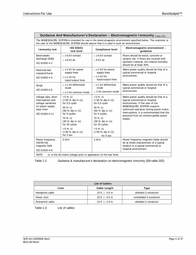
Guidance And Manufacturer’s Declaration – Electromagnetic Immunity (Table 202)
The BONESCALPEL SYSTEM is intended for use in the electromagnetic environment specified below. The customer orthe user of the BONESCALPEL SYSTEM should assure that it is used in such an environment.
Immunity test IEC 60601test level
Compliance level Electromagnetic environment –guidance
Electrostaticdischarge (ESD)
IEC 61000-4-2
o ±6 kV contact
o ±8 kV air
o ±6 kV contact
o 8 kV air
Floors should be wood, concrete orceramic tile. If floors are covered withsynthetic material, the relative humidityshould be at least 30%.
Electrical fasttransient/burst
IEC 61000-4-4
o ±2 kV for powersupply lines
o±1 kV forinput/output lines
o ±2 kV for powersupply lines
o ±1 kV forinput/output lines
Mains power quality should be that of atypical commercial or hospitalenvironment.
Surge
IEC 61000-4-5
o ±1 kV differentialmode
o±2 kV common mode
o ±1 kV differentialmode
o 2 kV common mode
Mains power quality should be that of atypical commercial or hospitalenvironment.
Voltage dips, shortinterruptions andvoltage variationson power supplyinput lines
IEC 61000-4-11
<5 % UT
(>95 % dip in UT)for 0,5 cycle
40 % UT
(60 % dip in UT)for 5 cycles
70 % UT
(30 % dip in UT)for 25 cycles
<5 % UT
(>95 % dip in UT)for 5 sec
<5 % UT
(>95 % dip in UT)for 0,5 cycle
40 % UT
(60 % dip in UT)for 5 cycles
70 % UT
(30 % dip in UT)for 25 cycles
<5 % UT
(>95 % dip in UT)for 5 sec
Mains power quality should be that of atypical commercial or hospitalenvironment. If the user of theBONESCALPEL SYSTEM requirescontinued operation during power mainsinterruptions, it is recommended that thepowered from an uninterruptible powersupply.
Power frequency(50/60 Hz)magnetic field
IEC 61000-4-8
3 A/m 3 A/m Power frequency magnetic fields shouldbe at levels characteristic of a typicallocation in a typical commercial orhospital environment.
NOTE UT is the AC mains voltage prior to application of the test level.
Table 1.2 Guidance & manufacturer’s declaration on electromagnetic immunity (EN table 202)
List of Cables
Item Cable Length Type
Handpiece cable 15 ft | 4.6 m shielded 2-conductor
Power cord 10 ft | 3.0 m unshielded 3-conducter
Footswitch cable 14 ft | 4.3 m shielded 2-conductor
Table 1.3 List of cables
Instructions For Use BoneScalpel™
SOP-AIC-5000808 Rev2 Page 5 of 47BCA-UM RevD
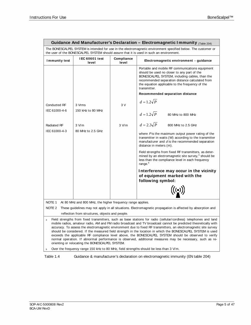
Guidance And Manufacturer’s Declaration – Electromagnetic Immunity (Table 204)
The BONESCALPEL SYSTEM is intended for use in the electromagnetic environment specified below. The customer orthe user of the BONESCALPEL SYSTEM should assure that it is used in such an environment.
Immunity test IEC 60601 testlevel
Compliancelevel Electromagnetic environment – guidance
Conducted RF
IEC 61000-4-6
Radiated RF
IEC 61000-4-3
3 Vrms
150 kHz to 80 MHz
3 V/m
80 MHz to 2.5 GHz
3 V
3 V/m
Portable and mobile RF communications equipmentshould be used no closer to any part of theBONESCALPEL SYSTEM, including cables, than therecommended separation distance calculated fromthe equation applicable to the frequency of thetransmitter.
Recommended separation distance
Pd 2.1
Pd 2.1 80 MHz to 800 MHz
Pd 3.2 800 MHz to 2.5 GHz
where P is the maximum output power rating of thetransmitter in watts (W) according to the transmittermanufacturer and d is the recommended separationdistance in meters (m).
Field strengths from fixed RF transmitters, as deter-mined by an electromagnetic site survey,a should beless than the compliance level in each frequencyrange.b
Interference may occur in the vicinityof equipment marked with thefollowing symbol:
NOTE 1 At 80 MHz and 800 MHz, the higher frequency range applies.
NOTE 2 These guidelines may not apply in all situations. Electromagnetic propagation is affected by absorption and
reflection from structures, objects and people.
a Field strengths from fixed transmitters, such as base stations for radio (cellular/cordless) telephones and landmobile radios, amateur radio, AM and FM radio broadcast and TV broadcast cannot be predicted theoretically withaccuracy. To assess the electromagnetic environment due to fixed RF transmitters, an electromagnetic site surveyshould be considered. If the measured field strength in the location in which the BONESCALPEL SYSTEM is usedexceeds the applicable RF compliance level above, the BONESCALPEL SYSTEM should be observed to verifynormal operation. If abnormal performance is observed, additional measures may be necessary, such as re-orienting or relocating the BONESCALPEL SYSTEM.
b Over the frequency range 150 kHz to 80 MHz, field strengths should be less than 3 V/m.
Table 1.4 Guidance & manufacturer’s declaration on electromagnetic immunity (EN table 204)

Instructions For Use BoneScalpel™
SOP-AIC-5000808 Rev2 Page 6 of 47BCA-UM RevD
Recommended Separation Distances Between Portable And Mobile RFCommunications Equipment And The BONESCALPEL SYSTEM (Table 206)
The BONESCALPEL SYSTEM is intended for use in an electromagnetic environment in which radiated RF disturbancesare controlled. The customer or the user of the BONESCALPEL SYSTEM can help prevent electromagnetic interferenceby maintaining a minimum distance between portable and mobile RF communications equipment (transmitters) andthe BONESCALPEL SYSTEM below, according to the maximum output power of the communications equipment.
Separation distance according to frequency of transmitterMRated maximum output
powerof transmitter
W150 kHz to 80 MHz
Pd 2.1
80 MHz to 800 MHz
Pd 2.1
800 MHz to 2,5 GHz
Pd 3.20.01 0.12 0.12 0.23
0.1 0.37 0.37 0.37
1 1.2 1.2 2.3
10 3.7 3.7 7.4
100 12 12 23
For transmitters rated at a maximum output power not listed above, the recommended separation distance din meters (m) can be estimated using the equation applicable to the frequency of the transmitter, where P isthe maximum output power rating of the transmitter in watts (W) according to the transmitter manufacturer.NOTE 1 At 80 MHz and 800 MHz, the separation distance for the higher frequency range applies.NOTE 2 These guidelines may not apply in all situations. Electromagnetic propagation is affected by absorptionand reflection from structures, objects and people.
Table 1.5 Recommended separation distances (EN table 206)
1.2. Electrical Safety StatementThe BoneScalpel System is designed and tested to comply with UL 60601-1 and EN 60601-1.
WARNING 1.3 The BoneScalpel system generates high voltages within the console itself and the connected handpiece. To avoid injury,the console should never be operated before ensuring that its cover is properly closed and not tampered with. Do notattempt to remove or disassemble the cover. There are no user-serviceable parts inside the console. All service shouldonly be performed by an authorized Aesculap USA representative.
WARNING 1.4 Proper system grounding can only be ensured when an approved, hospital-grade receptacle and matching power cordare used. Install plug and receptacles as per local regulations before operating the unit. Power cord, plug andreceptacle should be examined to verify that they are in good working condition before connecting the console. Neverpull on the power cord to remove it from the receptacle.
WARNING 1.5 Connecting the console to a power outlet with inadequate voltage or frequency may cause the unit to malfunction or tocreate a shock or fire hazard. Confirm that the voltage selector switch on the console rear panel is set to the localvoltage setting and ensure that the correct fuses are being used. Refer to section 12.1 on fuse replacement.
1.3. Environmental StatementThis equipment consists of materials that may be recycled if disassembled by a specialized company. Pleaseobserve local and federal regulations regarding the disposal of packing materials and old equipment.
Instructions For Use BoneScalpel™
SOP-AIC-5000808 Rev2 Page 7 of 47BCA-UM RevD
1.4. Summary Of Safety Notices
Please read this section of the manual carefully. It contains a summary of all precaution, warning andcaution statements contained in the manual. However, the user is advised to read the entire manual andoperate the device only in accordance with all of the instructions contained herein.
Servicing of this device should only be performed by qualified technicians authorized by Aesculap USA.There are no service controls accessible to the user.
Conventions on Warnings, Cautions and Notes
WARNING Denotes potentially dangerous situation that could result in death or serious injury to patient,operator or staff.
CAUTION Denotes potentially dangerous situation that could result in moderate injury to patient, operator orstaff.
NOTE Indicates potential hazard that may result in product damage.
Table 1.6 Conventions on warnings, cautions and notes
List Of WarningsWARNING 1.1 The BoneScalpel system is an electro-mechanical device, which under certain circumstances could present an electrical
shock hazard to the operator and/or patient. Please read manual thoroughly and follow directions stated herein toassure maximum safety during operation. This manual shall be kept in close proximity to the system for easy referralwhen needed.
WARNING 1.2 The BoneScalpel system is intended to be used in various types of invasive, surgical procedures. There may be indirectdanger to the patient should the device fail during the procedure. It is recommended that the facility follows its back-upequipment protocols.
WARNING 1.3 The BoneScalpel system generates high voltages within the console itself and the connected handpiece. To avoid injury,the console should never be operated before ensuring that its cover is properly closed and not tampered with. Do notattempt to remove or disassemble the cover. There are no user-serviceable parts inside the console. All service shouldonly be performed by an authorized Aesculap USA representative.
WARNING 1.4 Proper system grounding can only be ensured when an approved, hospital-grade receptacle and matching power cordare used. Install plug and receptacles as per local regulations before operating the unit. Power cord, plug andreceptacle should be examined to verify that they are in good working condition before connecting the console. Neverpull on the power cord to remove it from the receptacle.
WARNING 1.5 Connecting the console to a power outlet with inadequate voltage or frequency may cause the unit to malfunction or tocreate a shock or fire hazard. Confirm that the voltage selector switch on the console rear panel is set to the localvoltage setting and ensure that the correct fuses are being used. Refer to section 12.1 on fuse replacement.
WARNING 3.1 Tip and irrigant temperatures may exceed the tissue necrosis point if insufficient irrigation flow rates are used. Forhard tissue removal , set the irrigation flowrate to a setting no less than the comparable vibrationsetting. For example, if the vibration setting is 7, a minimum flow setting of 70% should be used. Additional externalirrigation, e.g. by administering sterile saline with a syringe over the distal tip portion, may be necessary for removal ofvery dense, hard osseous structures.
WARNING 3.2 Tissue necrosis may result if tip is not moved relative to tissue. A continuous tip motion is recommended inorder to minimize contact duration with the ultrasonic tip and minimize heat build-up. When lateral motion is notpossible withdraw and re-insert tip frequently.
WARNING 4.1 Contact to vibrating elements like extension and ultrasonic tip may cause burns and should be avoided by all means.The handpiece should only be held at the black housing area. A protective silicone sleeve, included with certain tips,reduces the risk of thermal damage but does not eliminate it. Contact with the silicone sleeve should be avoided or keptbrief with minimal amount of contact pressure. Pressure and extended exposure can still result in excessive frictional
Instructions For Use BoneScalpel™
SOP-AIC-5000808 Rev2 Page 8 of 47BCA-UM RevD
heat and cause burns.
WARNING 4.2 Additional external irrigation, e.g. by administering sterile saline with a syringe over the distal tip portion, may benecessary for removal of very dense, hard osseous structures of the skull, when using the BoneScalpel accessories.
WARNING 4.3 Ultrasonic tips can break under excessive use in extreme conditions, e.g. when cutting for extended duration in tightcavities with limited lateral motion. The tip could break into two or more fragments with the main fragment remainingattached to the handpiece. All fragments must be retrieved immediately from the surgical site. The fragments should bechecked to ensure that no further pieces are missing. It is possible that a fragment is propelled outside of the surgicalcavity. Diagnostic imaging, such as X-ray, must be used if a fragment cannot be found to confirm that the broken pieceis outside of the surgical cavity.
WARNING 4.4 Breakage of ultrasonic tips will result in sharp edges that can be harmful to soft tissue even without activation ofultrasound. Tips can bend or deform before they actually brake. Tips showing signs of deformation or cracking shouldbe replaced immediately since tip breakage is otherwise imminent. Do not bend or twist the ultrasonic tips since itreduces the structural integrity and can result in tip breakage during use. Dispose of deformed or broken tipsimmediately in a sharps container.
WARNING 6.1 Immediately suspend operation if Electrical Fault appears on display and/or an Electrical Fault audible alarm sounds.Remove ultrasonic tip from surgical site. Turn Mains Power OFF. Do not touch any metallic parts of handpiece,extension, ultrasonic tip or generator while fault is indicated.
WARNING 7.1 Improper connection of the handpiece cable may present a shock hazard. Confirm that handpiece connector is dry priorto plugging it in.
WARNING 7.2 Do not operate pump with pump cover in raised position. Rollers might pinch loose clothing or fingers. Personalinjuries may result. Cooling of the ultrasonic tip and irrigation at the treatment site will be inhibited.
WARNING 7.3 Tip and irrigation temperatures may exceed the tissue necrosis point with BoneScalpel accessories for hard tissueremoval if insufficient irrigation flow rates are used. Always set the irrigation flowrate for hard tissue removalto a setting no less than the comparable vibration setting. For example, if the vibration setting is 7, a minimumflow setting of 70% should be used.
WARNING 7.4 Heat is being generated at the tip/tissue interface. A continuous, lateral sweeping motion is recommended for generalbone/tissue removal in order to minimize contact duration with the ultrasonic tip and minimize the temperatureincrease.
WARNING 8.1 Remove probe cover, ultrasonic tip and extension from the handpiece prior to cleaning and/or sterilization; otherwiseproper cleaning/sterilization may be inhibited.
WARNING 9.1 Single-use items should be discarded following each surgical procedure according to hospital protocol for disposal ofbiocontaminated wastes. Do not attempt to reuse or re-sterilize any single-use items. Dispose ultrasonic tipsin a sharps container.
WARNING 9.2 All reusable handpiece parts and accessories must be properly decontaminated, cleaned and sterilized before each useas per instructions contained in this manual. Failure to do so may lead to infections, which can ultimately cause patientdeath.
WARNING 9.3 The manufacturer has validated all cleaning and sterilization cycles given in this manual. It is highly recommended thatthe procedures given in this manual for cleaning and sterilizing the BoneScalpel System and related accessories befollowed. It is the responsibility of the user of this device or any accessories used with it to validate procedures forcleaning and/or sterilization if they differ from the procedures as outlined in this manual.
WARNING 10.1 If a Mains Power fuse fails after replacement when the unit is reactivated, discontinue use of the device and contact anauthorized Aesculap USA representative.
WARNING 12.1 Connecting the console to a power outlet with inadequate voltage or frequency may cause the unit to malfunction or tocreate a shock or fire hazard. Confirm that the voltage selector switch in the console rear is set to the local voltagesetting and ensure that the correct fuses are being used. Refer to section 12 on fuse replacement
List Of CautionsCAUTION 1.1 Federal law restricts this device to sale by or on the order of a licensed healthcare practitioner
CAUTION 1.2 This device is considered medical electrical equipment. Medical electrical equipment needs special precautions regardingelectromagnetic compatibility (EMC) and needs to be installed and put into service according to the EMC informationprovided in this operator’s manual.
CAUTION 1.3 Portable and mobile RF communication equipment can affect medical electrical equipment. If RF equipment is in usemonitor the Bonescalpel for proper function during procedure.
CAUTION 1.4 The use of accessories, transducers and cables other than those specified may result in increased emissions or
Instructions For Use BoneScalpel™
SOP-AIC-5000808 Rev2 Page 9 of 47BCA-UM RevD
decreased immunity of the device. Use only Aesculap branded equipment and accessories.
CAUTION 1.5 The console should not be used adjacent to or stacked with other electrical equipment. If adjacent or stacked use isnecessary, the console should be observed to verify normal operation in the configuration in which it will be used.
CAUTION 3.1 The BoneScalpel system and its accessories may emit harmful acoustic pressure if exposure exceeds recommendedlimits.
CAUTION 4.1 Ultrasonic energy is inhibited if excessive physical force is applied to the ultrasonic tip; use only enough force to guidethe tip to the surgical site and to advance it through the tissue. Do not force the tip; allow the ultrasonic action to dothe work.
CAUTION 4.2 Insufficient irrigation and high tip pressure (loading) under extended exposure, e.g. in tight cavities, are to be avoidedin BoneScalpel hard tissue removal. It is recommended to withdraw and re-insert the ultrasonic tip repeatedly to re-establish adequate cooling and lubrication.
CAUTION 7.1 All reusable system components like handpiece, probe covers, counter wrench, and T-wrench are supplied industriallycleaned, but NON-STERILE. All items intended for use in the sterile field must be cleaned and sterilized as per theindicated instructions before first clinical use and before every subsequent clinical use.
CAUTION 7.2 All items intended for use in the sterile field must be cleaned and sterilized as per indicated instructions before eachclinical use.
CAUTION 7.3 The disposable items are intended for one procedure only (single use). Do not attempt to reuse or re-sterilize.
CAUTION 7.4 Do not place the soft silicone tube behind or in front of the rollers (latch removed in illustrations)
CAUTION 7.5 Do not pinch the soft silicone tube when the latch is locked.
CAUTION 7.6 Do not pinch barb fittings when closing the latch.
CAUTION 7.7 Prime the irrigation tubing prior to use. At all times ensure that the irrigant flows towards the handpiece whenfootswitch is depressed. If no irrigant is flowing, cease use until flow is restored.
CAUTION 7.8 The system check should always be done in advance of preparing patient for surgery to minimize risk to patient in caseof system malfunction.
CAUTION 8.1 Ensure all connections and mating surfaces of handpiece, extension and ultrasonic tip are clean and dry beforeassembly.
CAUTION 9.1 Use manual cleaning techniques only. Do not use ultrasonic cleaners or automated washers to clean the handpiece asboth methods could damage handpiece.
CAUTION 9.2 Be certain to clear debris from all internal passages by brushing. Failure to do so may hinder sterilization of unitsduring autoclaving.
CAUTION 9.3 Do not immerse ultrasonic console, handpiece, irrigation pump, remote footswitch or electric cables. These items arenot sealed against liquids and damage to equipment will result.
CAUTION 12.1 Use only genuine replacement parts from Aesculap. Use of parts furnished by other sources may result in patient oroperator injury or system malfunction and will void any applicable warranty.
CAUTION 12.2 Before using loose packing materials, such as foam pellets, shredded paper or similar, be sure to wrap thecomponent(s) separately in plastic bags, film or other protective wrapping.
List Of NotesNOTE 4.1 After extended periods of operation, the bottom of the console housing may become warm to the touch. This is normal.
Do not touch the bottom of the console housing while in operation or shortly after operation.
NOTE 4.2 Loose tip/tissue contact upon an initial bone incision can cause a thin tip to resonate not only longitudinally but alsotransversely. This can cause a thin tip to break. It is necessary to engage bone actively and with a minimal tip pressuregreater than zero in order to prevent the shattering.
NOTE 4.3 Contact of the ultrasonic tip or the exposed extension with metal, surgical instruments or other objects duringultrasound use must be avoided. Such contact can damage the ultrasonic components very easily and may result incompromised performance, including failure. Discard any extensions or tips that show signs of damages like gouges,nicks or fractures. External aspiration may be used but it is recommended that a plastic suction tip should be usedwhen in proximity with the probe tip.
NOTE 7.1 Adequate air circulation is needed to cool electronic components inside of the unit. Do not block the cooling fan at theconsole rear or the air vents on the console bottom. Do not place the unit on a towel, foam or other soft surface sincethe material may block the air vents. Blocking these vents may cause unit to overheat and malfunction or create ashock hazard. A clear drape can be used to protect the console front panel but do not cover the pump housing or otherconsole portions.
Instructions For Use BoneScalpel™
SOP-AIC-5000808 Rev2 Page 10 of 47BCA-UM RevD
NOTE 8.1 The handpiece must be placed into the counter wrench. Do not attempt to tighten or loosen handpiece components byholding the handpiece case or endcap. Always use the T-wrench wrench when tightening or un-tightening the tip or anextension. Never apply a pipe or strap wrench to the handpiece case. Do not over-tighten the tip or the extension.
NOTE 8.2 Always tighten or un-tighten the probe cover by hand and without using any wrenches. Do not over-tighten the probecover.
NOTE 8.3 Always hold the handpiece at its metallic endcap when tightening or un-tightening the irrigation tubing. Always tightenor un-tighten the irrigation tubing by hand and without using any wrenches. Do not over-tighten the tubing connector.
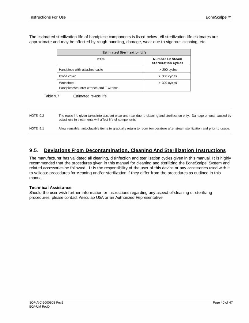
NOTE 9.1 Allow reusable, autoclavable items to gradually return to room temperature after steam sterilization and prior to usage.
NOTE 9.2 The reuse life given takes into account wear and tear due to cleaning and sterilization only. Damage or wear caused byactual use in treatments will affect life of components.
1.5. Trademark InformationAesculap® is a registered trademark of Aesculap, Inc.Misonix® is a registered trademarks of Misonix, Inc., Farmingdale, NYBoneScalpel™ is a pending trademark of Misonix, Inc., Farmingdale, NYASP Enzol® and Prolystica® are registered trademarks of STERIS Corporation, Mentor, OH
Instructions For Use BoneScalpel™
SOP-AIC-5000808 Rev2 Page 11 of 47BCA-UM RevD
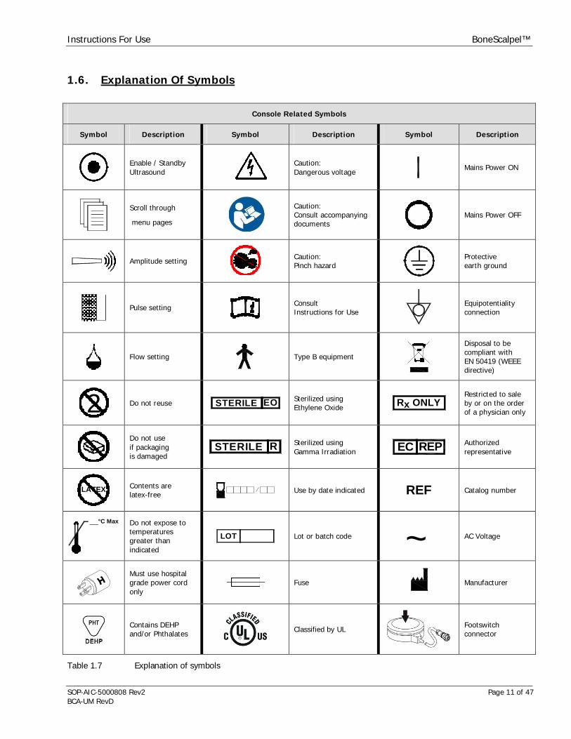
1.6. Explanation Of Symbols
Console Related Symbols
Symbol Description Symbol Description Symbol Description
Enable / StandbyUltrasound
Caution:Dangerous voltage
Mains Power ON
Scroll through
menu pages
Caution:Consult accompanyingdocuments
Mains Power OFF
Amplitude setting Caution:Pinch hazard
Protectiveearth ground
Pulse setting ConsultInstructions for Use
Equipotentialityconnection
Flow setting Type B equipment
Disposal to becompliant withEN 50419 (WEEEdirective)
2 Do not reuse STERILE EO Sterilized usingEthylene Oxide R ONLYx
Restricted to saleby or on the orderof a physician only
Do not useif packagingis damaged
STERILE R Sterilized usingGamma Irradiation EC REP Authorized
representative
LATEX Contents arelatex-free Use by date indicated REF Catalog number
°C Max Do not expose totemperaturesgreater thanindicated
LOT Lot or batch code ~ AC Voltage
Must use hospitalgrade power cordonly
Fuse Manufacturer
Contains DEHPand/or Phthalates Classified by UL Footswitch
connector
Table 1.7 Explanation of symbols

Instructions For Use BoneScalpel™
SOP-AIC-5000808 Rev2 Page 12 of 47BCA-UM RevD
2. Indications And Contra Indications2.1. IndicationsThe BoneScalpel system is indicated for use in the fragmentation and aspiration of both soft and hard (e.g.:bone) tissue as used in the following surgical specialties:
Orthopedic SurgeryPlastic and Reconstructive SurgeryThoracic SurgeryNeuroSurgeryGeneral Surgery
CAUTION 1.1 Federal law restricts this device to sale by or on the order of a licensed healthcare practitioner
2.2. Contra IndicationsThe BoneScalpel system is contra indicated for cardiac surgery and any procedure in the proximity of the heart.
The irrigation pump is contra indicated for the administration of parenteral fluids, infusion of drugs or for anylife sustaining purposes
Instructions For Use BoneScalpel™
SOP-AIC-5000808 Rev2 Page 13 of 47BCA-UM RevD
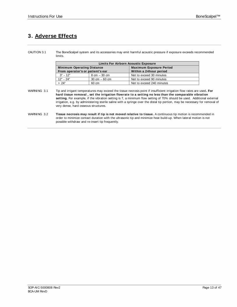
3. Adverse Effects
CAUTION 3.1 The BoneScalpel system and its accessories may emit harmful acoustic pressure if exposure exceeds recommendedlimits.
Limits For Airborn Acoustic ExposureMinimum Operating DistanceFrom operator’s or patient’s ear
Maximum Exposure PeriodWithin a 24hour period
3” - 12” 8 cm – 30 cm Not to exceed 30 minutes12” - 24” 30 cm – 60 cm Not to exceed 90 minutes> 24” 60 cm Not to exceed 240 minutes
WARNING 3.1 Tip and irrigant temperatures may exceed the tissue necrosis point if insufficient irrigation flow rates are used. Forhard tissue removal , set the irrigation flowrate to a setting no less than the comparable vibrationsetting. For example, if the vibration setting is 7, a minimum flow setting of 70% should be used. Additional externalirrigation, e.g. by administering sterile saline with a syringe over the distal tip portion, may be necessary for removal ofvery dense, hard osseous structures.
WARNING 3.2 Tissue necrosis may result if tip is not moved relative to tissue. A continuous tip motion is recommended inorder to minimize contact duration with the ultrasonic tip and minimize heat build-up. When lateral motion is notpossible withdraw and re-insert tip frequently.
Instructions For Use BoneScalpel™
SOP-AIC-5000808 Rev2 Page 14 of 47BCA-UM RevD
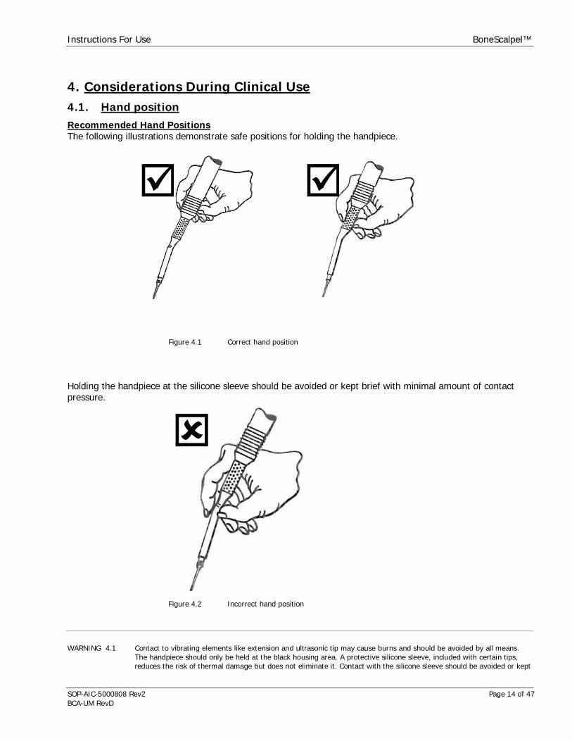
4. Considerations During Clinical Use4.1. Hand positionRecommended Hand PositionsThe following illustrations demonstrate safe positions for holding the handpiece.
Figure 4.1 Correct hand position
Holding the handpiece at the silicone sleeve should be avoided or kept brief with minimal amount of contactpressure.
Figure 4.2 Incorrect hand position
WARNING 4.1 Contact to vibrating elements like extension and ultrasonic tip may cause burns and should be avoided by all means.The handpiece should only be held at the black housing area. A protective silicone sleeve, included with certain tips,reduces the risk of thermal damage but does not eliminate it. Contact with the silicone sleeve should be avoided or kept

Instructions For Use BoneScalpel™
SOP-AIC-5000808 Rev2 Page 15 of 47BCA-UM RevD
brief with minimal amount of contact pressure. Pressure and extended exposure can still result in excessive frictionalheat and cause burns.
NOTE 4.1 After extended periods of operation, the bottom of the console housing may become warm to the touch. This is normal.Do not touch the bottom of the console housing while in operation or shortly after operation.
4.2. HARD Tissue UseRecommended Settings For Hard Tissue UseThe following settings are general guidelines and should be adjusted based on indication, anatomy, pathologyand surgeon’s preference.
Amplitude Pulse FlowHighest 10 100% 100%Very High 9 100% 90%High 8 100% 80%Standard (Default) 7 100% 70%Moderate 6 100% 60%Low 5 100% 50%
Table 4.1 Recommended settings for hard tissue removal
A high amplitude setting results in more aggressive tissue removal, a low setting in less aggressive tissueremoval.A higher amplitude setting in combination with lower irrigation could result in increased tissue necrosis. Alower amplitude setting in combination with higher irrigation would minimize or eliminate tissue necrosis.Bone shaving tips tend to require a lower amplitude than cutting blades.
WARNING 3.1 Tip and irrigant temperatures may exceed the tissue necrosis point if insufficient irrigation flow rates are used. For hardtissue removal , set the irrigation flowrate to a setting no less than the comparable vibration setting. For example, if thevibration setting is 7, a minimum flow setting of 70% should be used. Additional external irrigation, e.g. byadministering sterile saline with a syringe over the distal tip portion, may be necessary for removal of very dense, hardosseous structures.
WARNING 3.2 Tissue necrosis may result if tip is not moved relative to tissue. A continuous tip motion is recommended in order tominimize contact duration with the ultrasonic tip and minimize heat build-up. When lateral motion is not possiblewithdraw and re-insert tip frequently.
WARNING 4.2 Additional external irrigation, e.g. by administering sterile saline with a syringe over the distal tip portion, may benecessary for removal of very dense, hard osseous structures of the skull, when using the BoneScalpel accessories.
CAUTION 4.1 Ultrasonic energy is inhibited if excessive physical force is applied to the ultrasonic tip; use only enough force to guidethe tip to the surgical site and to advance it through the tissue. Do not force the tip; allow the ultrasonic action to dothe work.

Instructions For Use BoneScalpel™
SOP-AIC-5000808 Rev2 Page 16 of 47BCA-UM RevD
Tip Limitations During Bone RemovalBoth the ultrasonic tip and the extension are vibrating at high frequency and are thus exposed to extrememechanical stresses, especially when cutting bone.
WARNING 4.3 Ultrasonic tips can break under excessive use in extreme conditions, e.g. when cutting for extended duration in tightcavities with limited lateral motion. The tip could break into two or more fragments with the main fragment remainingattached to the handpiece. All fragments must be retrieved immediately from the surgical site. The fragments should bechecked to ensure that no further pieces are missing. It is possible that a fragment is propelled outside of the surgicalcavity. Diagnostic imaging, such as X-ray, must be used if a fragment cannot be found to confirm that the broken pieceis outside of the surgical cavity.
WARNING 4.4 Breakage of ultrasonic tips will result in sharp edges that can be harmful to soft tissue even without activation ofultrasound. Tips can bend or deform before they actually brake. Tips showing signs of deformation or cracking shouldbe replaced immediately since tip breakage is otherwise imminent. Do not bend or twist the ultrasonic tips since itreduces the structural integrity and can result in tip breakage during use. Dispose of deformed or broken tipsimmediately in a sharps container.
CAUTION 4.2 Insufficient irrigation and high tip pressure (loading) under extended exposure, e.g. in tight cavities, are to be avoidedin BoneScalpel hard tissue removal. It is recommended to withdraw and re-insert the ultrasonic tip repeatedly to re-establish adequate cooling and lubrication.
NOTE 4.2 Loose tip/tissue contact upon an initial bone incision can cause a thin tip to resonate not only longitudinally but alsotransversely. This can cause a thin tip to break. It is necessary to engage bone actively and with a minimal tip pressuregreater than zero in order to prevent the shattering.
NOTE 4.3 Contact of the ultrasonic tip or the exposed extension with metal, surgical instruments or other objects duringultrasound use must be avoided. Such contact can damage the ultrasonic components very easily and may result incompromised performance, including failure. Discard any extensions or tips that show signs of damages like gouges,nicks or fractures. External aspiration may be used but it is recommended that a plastic suction tip should be usedwhen in proximity with the probe tip.

Instructions For Use BoneScalpel™
SOP-AIC-5000808 Rev2 Page 17 of 47BCA-UM RevD
5. System Overview5.1. Principle Of OperationThe BoneScalpel system is designed to ultrasonically dissect and fragment hard (osseous) tissues. The systemconsists of an ultrasonic console with handpiece and accessories. The console features an integrated irrigationpump.
Figure 5.1 BoneScalpel Console
Figure 5.2 BoneScalpel Handpiece
The console produces an electrical signal that is fed into the handpiece and its piezoelectric transducer. Thetransducer converts the electrical signal into mechanical vibrations. The vibratory motion is amplified all the waydown to the tip’s distal end. Various tip shapes and sizes are available to achieve desired tissue effects.
Hard Tissue Applications: Specialized hard tissue tips are utilized to cut hard, osseous structures.
o BoneScalpel blades, typically used for performing osteotomies, are usually flat and have a bluntactive edge. A compression cut is achieved through repetitive impacts on the bone at anultrasonic frequency.
o Bone shaving tips are used for sculpting bone. They have an abrasive surface for bone removalthrough abrasion under ultrasonic oscillation.
o BoneScalpel multi-function tips can have a combination of blunt and abrasive cutting surfaces.
A peristaltic pump, integrated into the BoneScalpel console, provides irrigant to the operative site during use.
Instructions For Use BoneScalpel™
SOP-AIC-5000808 Rev2 Page 18 of 47BCA-UM RevD
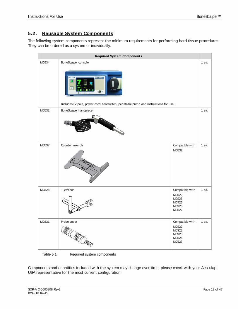
5.2. Reusable System ComponentsThe following system components represent the minimum requirements for performing hard tissue procedures.They can be ordered as a system or individually.
Table 5.1 Required system components
Components and quantities included with the system may change over time, please check with your AesculapUSA representative for the most current configuration.
Required System Components
MC634 BoneScalpel console
Includes IV pole, power cord, footswitch, peristaltic pump and instructions for use
1 ea.
MC632 BoneScalpel handpiece 1 ea.
MC637 Counter wrench Compatible with
MC632
1 ea.
MC628 T-Wrench Compatible with
MC922MC923MC925MC926MC927
1 ea.
MC631 Probe cover Compatible with
MC922MC923MC925MC926MC927
1 ea.

Instructions For Use BoneScalpel™
SOP-AIC-5000808 Rev2 Page 19 of 47BCA-UM RevD
5.3. Single-use, Sterile ComponentsAt least one irrigation tubeset must be available for each surgical procedure.
Irrigation Tubeset
MC924 Irrigation Tubeset 1 ea.
Table 5.2 Irrigation tubeset
Ultrasonic tips are supplied sterile and are for single use only. At least one of the following tips must beavailable for each surgical procedure.
Hard Tissue TipsAll tips requires MC631 probe cover
MC922 Bone Scalpel – 10mm, Blunt
Includes blade, short extension, and silicone sleeve
1 ea.
MC923 Bone Scalpel – 20mm, Blunt
Includes blade, short extension, and silicone sleeve
1 ea.
MC928 BoneScalpel –20mm, serrated blade
Includes blade, short extension,and silicone sleeve
1 ea.
MC925 Bone Shaver – Micro Hook
Includes shaver tip, short extension and silicone sleeve
1 ea.
MC927 Bone Scalpel – 10mm, Blunt, Long Straight
Includes blade, long curved extension, and silicone sleeve
1 ea.
MC926 Bone Scalpel – 10mm, Blunt, Long Curved
Includes blade, long curved extension, and silicone sleeve
1 ea.
Instructions For Use BoneScalpel™
SOP-AIC-5000808 Rev2 Page 20 of 47BCA-UM RevD
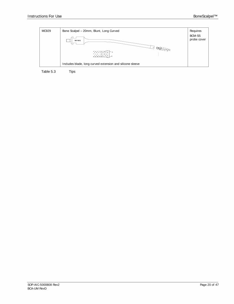
MC929 Bone Scalpel – 20mm, Blunt, Long Curved
Includes blade, long curved extension and silicone sleeve
Requires
BCM-SSprobe cover
Table 5.3 Tips

Instructions For Use BoneScalpel™
SOP-AIC-5000808 Rev2 Page 21 of 47BCA-UM RevD
6. Console6.1. Receptacles, Controls And IndicatorsThe rear of the console features receptacles for the power cord, fuses, footswitch cable and IV-pole as well as aswitch for mains power.
1 IV-pole receptacle2 Mains power on/off3 Power cord receptacle with
fuse block4 Voltage selector switch5 Cooling fan6 Equipotentiality connection7 Footswitch receptacle
Figure 6.1 Console rear
The front of the console features a receptacle for the handpiece cable and an irrigation pump head, in whichthe irrigation tubing is inserted. A large color LCD screen provides information on system status and set pointsfor ultrasound amplitude, pulse rate and irrigant flow rate with respective controls on the panel below.Additional controls for ultrasound enable/standby and menu access are provided on the left of the display panel.An ultrasound timer indicates the elapsed time, in which the ultrasound was on.
1 Amplitude setting2 Pulse setting3 Flow setting4 Enable/standby button5 Ultrasound timer6 Menu button7 Handpiece cable receptacle8 Indicator for flow direction9 Irrigation pump headA-F Custom buttons
Figure 6.2 Console front
Buttons A-F perform various functions, depending on the information displayed on the screen. The displayscreen shown is the Main Screen used for all major control functions.
The handpiece receptacle is keyed in order to facilitate connection. The red dot on top of the receptacle mustbe in line with the corresponding red dot on the handpiece cable.
Instructions For Use BoneScalpel™
SOP-AIC-5000808 Rev2 Page 22 of 47BCA-UM RevD
6.2. Menu FunctionsThe standard screen is the Main Screen. Additional screens are the Options and the Help Screen. Both theOptions and Help screens can be accessed by pressing the menu button to toggle through the three mainscreens; Main Menu, Options and Help.
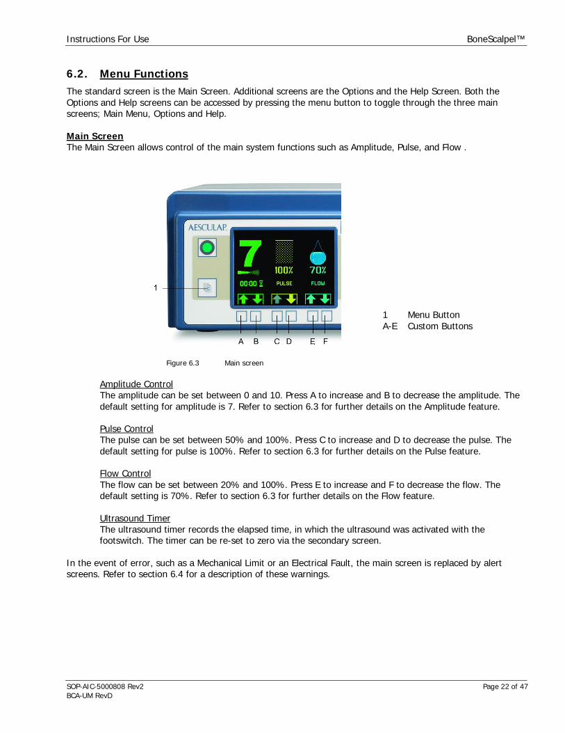
Main ScreenThe Main Screen allows control of the main system functions such as Amplitude, Pulse, and Flow .
1 Menu ButtonA-E Custom Buttons
Figure 6.3 Main screen
Amplitude ControlThe amplitude can be set between 0 and 10. Press A to increase and B to decrease the amplitude. Thedefault setting for amplitude is 7. Refer to section 6.3 for further details on the Amplitude feature.
Pulse ControlThe pulse can be set between 50% and 100%. Press C to increase and D to decrease the pulse. Thedefault setting for pulse is 100%. Refer to section 6.3 for further details on the Pulse feature.
Flow ControlThe flow can be set between 20% and 100%. Press E to increase and F to decrease the flow. Thedefault setting is 70%. Refer to section 6.3 for further details on the Flow feature.
Ultrasound TimerThe ultrasound timer records the elapsed time, in which the ultrasound was activated with thefootswitch. The timer can be re-set to zero via the secondary screen.
In the event of error, such as a Mechanical Limit or an Electrical Fault, the main screen is replaced by alertscreens. Refer to section 6.4 for a description of these warnings.
Instructions For Use BoneScalpel™
SOP-AIC-5000808 Rev2 Page 23 of 47BCA-UM RevD
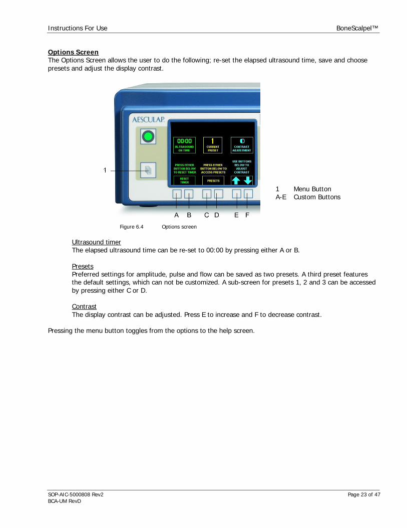
Options ScreenThe Options Screen allows the user to do the following; re-set the elapsed ultrasound time, save and choosepresets and adjust the display contrast.
1 Menu ButtonA-E Custom Buttons
Figure 6.4 Options screen
Ultrasound timerThe elapsed ultrasound time can be re-set to 00:00 by pressing either A or B.
PresetsPreferred settings for amplitude, pulse and flow can be saved as two presets. A third preset featuresthe default settings, which can not be customized. A sub-screen for presets 1, 2 and 3 can be accessedby pressing either C or D.
ContrastThe display contrast can be adjusted. Press E to increase and F to decrease contrast.
Pressing the menu button toggles from the options to the help screen.

Instructions For Use BoneScalpel™
SOP-AIC-5000808 Rev2 Page 24 of 47BCA-UM RevD
Help ScreenThe Help Screen provides access to a quick guide on system operation and troubleshooting.
1 Menu ButtonA-E Custom Buttons
Figure 6.5 Help screen
System OperationPress A to access the quick reference guide on system operation.
TroubleshootingPress B to access the quick reference guide on troubleshooting.
Pressing the menu button toggles from the help to the main screen.
6.3. Main FunctionsAmplitudeThe ultrasonic tip engages the target area in linear strokes at a rate of approximately 22,500 cycles per second.During each cycle the tip elongates from resting to maximum position, contracts back over resting and tominimum position and elongates back to its resting point. The peak-to-peak amplitude or stroke distance can beadjusted by changing the Amplitude from setting 1-10. This is the main parameter to control the rate of tissueremoval. A high amplitude setting results in more aggressive tissue removal, a low setting in less aggressivetissue removal. Amplitude and thus removal rate may alter with size and geometry of the ultrasonic tip.
PulseThe ultrasonic energy output over time can be reduced by using the pulse mode, in which a resting period isinserted within the duty cycle. This results in an active period, followed by a resting period during each dutycycle. The total period is a ¼ second (250ms). The pulse can be set between 50% and 100%.
Pulse Setting 100% [Continuous]The default setting is 100% or continuous, which refers to 100% energy output or zero resting period. This isthe recommended setting for hard tissue applications.
Pulse Setting 50-90% [Pulsed]The Pulse function minimizes exposure to ultrasound over time.

Instructions For Use BoneScalpel™
SOP-AIC-5000808 Rev2 Page 25 of 47BCA-UM RevD
The Pulse setting corresponds to the duration of the active period of the ultrasound output. For example, aPulse setting of 60% corresponds to an active period of 60% of ¼ second (150ms). The resulting resting periodis 40% of ¼ second (100ms). The ultrasonic energy output over time is reduced by 40% with this setting. Notethat the ultrasound timer will only advance during the active period and not during the resting period. For mostapplications, the recommended pulse setting is 100%.
Figure 6.6 Illustration of pulse setting
IrrigationProper irrigation with sterile saline ensures:
1) Cooling of handpiece and vibrating elements2) Cooling and lavage of the surgical site3) Lubrication of bone/tip interface for BoneScalpel hard tissue removal
The active ultrasonic probe remains cold when not in contact with tissue. However, when a tip contacts tissueheat is generated. The heat increases with applied tip pressure or amplitude. Irrigant needs to be applied at thetip/tissue interface to mitigate this temperature rise.
Most ultrasonic tips and probes feature an integrated irrigation channel. The irrigant is expelled through a jetnozzle at the tip. Active tip surfaces are being cooled directly.
Instructions For Use BoneScalpel™
SOP-AIC-5000808 Rev2 Page 26 of 47BCA-UM RevD
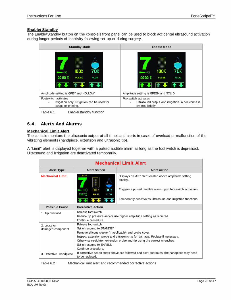
Enable/StandbyThe Enable/Standby button on the console’s front panel can be used to block accidental ultrasound activationduring longer periods of inactivity following set-up or during surgery.
Standby Mode Enable Mode
Amplitude setting is GREY and HOLLOW Amplitude setting is GREEN and SOLID
Footswitch activatesIrrigation only. Irrigation can be used forlavage or priming.
Footswitch activatesUltrasound output and irrigation. A bell chime isemitted briefly.
Table 6.1 Enable/standby function
6.4. Alerts And AlarmsMechanical Limit AlertThe console monitors the ultrasonic output at all times and alerts in cases of overload or malfunction of thevibrating elements (handpiece, extension and ultrasonic tip).
A “Limit” alert is displayed together with a pulsed audible alarm as long as the footswitch is depressed.Ultrasound and Irrigation are deactivated temporarily.
Mechanical Limit AlertAlert Type Alert Screen Alert Action
Mechanical Limit Displays “LIMIT” alert located above amplitude settingdisplay.
Triggers a pulsed, audible alarm upon footswitch activation.
Temporarily deactivates ultrasound and irrigation functions.
Possible Cause Corrective Action
1. Tip overload Release footswitch.Reduce tip pressure and/or use higher amplitude setting as required.Continue procedure.
2. Loose ordamaged component
Release footswitch.Set ultrasound to STANDBY.Remove silicone sleeve (if applicable) and probe cover.Inspect extension probe and ultrasonic tip for damage. Replace if necessary.Otherwise re-tighten extension probe and tip using the correct wrenches.Set ultrasound to ENABLE.Continue procedure.
3. Defective Handpiece If corrective action steps above are followed and alert continues, the handpiece may needto be replaced.
Table 6.2 Mechanical limit alert and recommended corrective actions
Instructions For Use BoneScalpel™
SOP-AIC-5000808 Rev2 Page 27 of 47BCA-UM RevD
Tip overload can occur during hard tissue removal when applying excessive tip pressure or facing strong tissueresistance, e.g. from thick cortical bone. This can lead to stalling of the ultrasonic tip. A pulsed audible signalalerts of the stalling and the ultrasound is deactivated. Release the footswitch briefly and reduce the tippressure, e.g. by retrieving the ultrasonic tip. Depress the footswitch again and continue with reduced tippressure. Consider using higher amplitude setting or reduced loading if stalling persists.
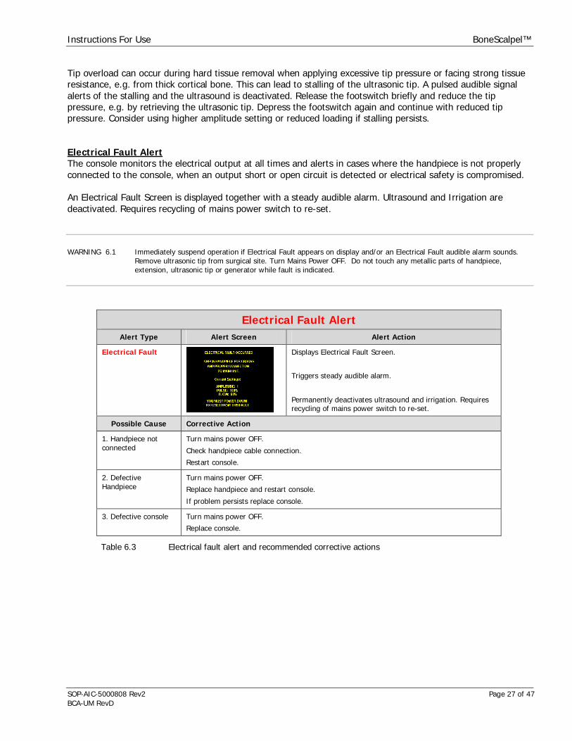
Electrical Fault AlertThe console monitors the electrical output at all times and alerts in cases where the handpiece is not properlyconnected to the console, when an output short or open circuit is detected or electrical safety is compromised.
An Electrical Fault Screen is displayed together with a steady audible alarm. Ultrasound and Irrigation aredeactivated. Requires recycling of mains power switch to re-set.
WARNING 6.1 Immediately suspend operation if Electrical Fault appears on display and/or an Electrical Fault audible alarm sounds.Remove ultrasonic tip from surgical site. Turn Mains Power OFF. Do not touch any metallic parts of handpiece,extension, ultrasonic tip or generator while fault is indicated.
Electrical Fault AlertAlert Type Alert Screen Alert Action
Electrical Fault Displays Electrical Fault Screen.
Triggers steady audible alarm.
Permanently deactivates ultrasound and irrigation. Requiresrecycling of mains power switch to re-set.
Possible Cause Corrective Action
1. Handpiece notconnected
Turn mains power OFF.
Check handpiece cable connection.
Restart console.
2. DefectiveHandpiece
Turn mains power OFF.
Replace handpiece and restart console.
If problem persists replace console.
3. Defective console Turn mains power OFF.
Replace console.
Table 6.3 Electrical fault alert and recommended corrective actions
Instructions For Use BoneScalpel™
SOP-AIC-5000808 Rev2 Page 28 of 47BCA-UM RevD
7. System Set-up7.1. InstallationUpon delivery perform a visual inspection of the shipping containers and all system components for obviousshipping damage. Retain the shipping container and immediately notify the shipping carrier of any damagesfound.
CAUTION 7.1 All reusable system components like handpiece, probe covers, counter wrench, and T-wrench are supplied industriallycleaned, but NON-STERILE. All items intended for use in the sterile field must be cleaned and sterilized as per theindicated instructions before first clinical use and before every subsequent clinical use.
The BoneScalpel system is designed and tested to comply with IEC EN60601-1-2: 2001 guidelines for EMC. Seesection 1 for general safety statements.
WARNING 1.5 Connecting the console to a power outlet with inadequate voltage or frequency may cause the unit to malfunction or tocreate a shock or fire hazard. Confirm that the voltage selector switch on the console rear panel is set to the localvoltage setting and ensure that the correct fuses are being used. Refer to section 12.1 on fuse replacement.See section12.1 for instructions on adjusting to local electrical requirements.
Care should be taken to stay within the general operating conditions.
Operating Conditions
Operating conditions Temperature 55-95 F (13-35 C)
Relative humidity 20-90% (non condensing)
Standard atmospheric pressure
Table 7.1 Operating conditions
The console can be placed on an appropriate table or cart outside of the sterile field. Ensure that the pumphead on the console right is installed. Refer to section 12.2 if the pump head is not yet installed.
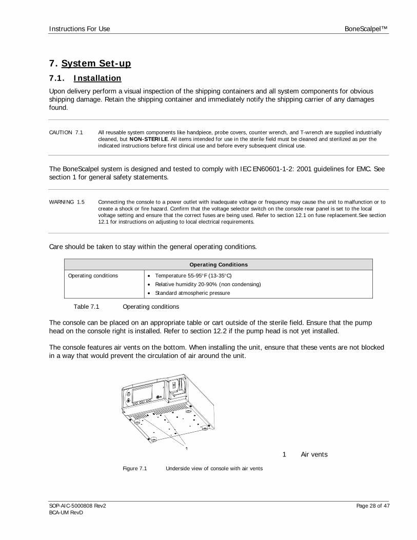
The console features air vents on the bottom. When installing the unit, ensure that these vents are not blockedin a way that would prevent the circulation of air around the unit.
1 Air vents
Figure 7.1 Underside view of console with air vents

Instructions For Use BoneScalpel™
SOP-AIC-5000808 Rev2 Page 29 of 47BCA-UM RevD
NOTE 7.1 Adequate air circulation is needed to cool electronic components inside of the unit. Do not block the cooling fan at theconsole rear or the air vents on the console bottom. Do not place the unit on a towel, foam or other soft surface sincethe material may block the air vents. Blocking these vents may cause unit to overheat and malfunction or create ashock hazard. A clear drape can be used to protect the console front panel but do not cover the pump housing or otherconsole portions.
7.2. Console Set-up – Part I (Non-sterile)
Console Set-up | Part I
Switch Mains Power OFF Set Mains Power switch on console rear to OFF.
Connect IV-pole Connect IV-pole to receptacle in console rear.
Hang container with sterile irrigant into IV-pole hook.
Irrigation tubing features IV-spike and is compatible with rigid bottles or flexible bags.
Connect Electrical Power Connect power cord to receptacle on console rear and to wall outlet.
Connect Footswitch Connect footswitch cable to receptacle on console rear.
Footswitch connector and receptacle are keyed to ensure proper connection. Turn cableconnector until keys match. Insert connector fully into receptacle. Turn outer connectorring clockwise to lock into position.
Footswitch may be covered with clear drape during clinical use.
Switch Mains Power ON Set Mains Power switch on console rear to ON.
Front panel will display Main Screen upon completion of system start.
Table 7.2 Console set-up - part I
7.3. Handpiece Assembly (Sterile)Handpiece assembly in the sterile field should be performed by trained and authorized OR staff only.
Please refer to section 8.0 for specifics on the handpiece assembly and disassembly for both hard tissueapplications.
Once the handpiece has been assembled, continue with part II of the Console Set Up.
CAUTION 7.2 All items intended for use in the sterile field must be cleaned and sterilized as per indicated instructions before eachclinical use.
CAUTION 7.3 The disposable items are intended for one procedure only (single use). Do not attempt to reuse or re-sterilize.
Instructions For Use BoneScalpel™
SOP-AIC-5000808 Rev2 Page 30 of 47BCA-UM RevD
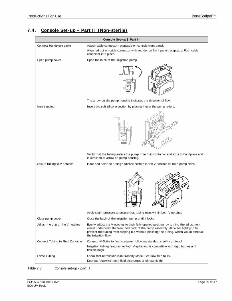
7.4. Console Set-up – Part II (Non-sterile)
Table 7.3 Console set-up - part II
Console Set-up | Part II
Connect Handpiece cable Attach cable connector receptacle on console front panel.
Align red dot on cable connector with red dot on front panel receptacle. Push cableconnector into place.
Open pump cover Open the latch of the irrigation pump
The arrow on the pump housing indicates the direction of flow.
Insert tubing Insert the soft silicone section by placing it over the pump rollers.
Verify that the tubing enters the pump from fluid container and exits to handpiece andin direction of arrow on pump housing.
Secure tubing in V-notches Place and hold the tubing’s silicone section in the V-notches on both pump sides.
Apply slight pressure to ensure that tubing rests within both V-notches.
Close pump cover Close the latch of the irrigation pump until it locks.
Adjust the grip of the V-notches Evenly adjust the V-notches to their fully opened position by turning the adjustmentwheel underneath the front and back of the pump assembly. Allow for tight grip toprevent the tubing from slipping but without pinching the tubing, which would obstructthe irrigation flow.
Connect Tubing to Fluid Container Connect IV-Spike to fluid container following standard sterility protocol.
Irrigation tubing features vented IV-spike and is compatible with rigid bottles andflexible bags.
Prime Tubing Check that ultrasound is in Standby Mode. Set Flow rate to 10.
Depress footswitch until fluid discharges at ultrasonic tip.
Instructions For Use BoneScalpel™
SOP-AIC-5000808 Rev2 Page 31 of 47BCA-UM RevD
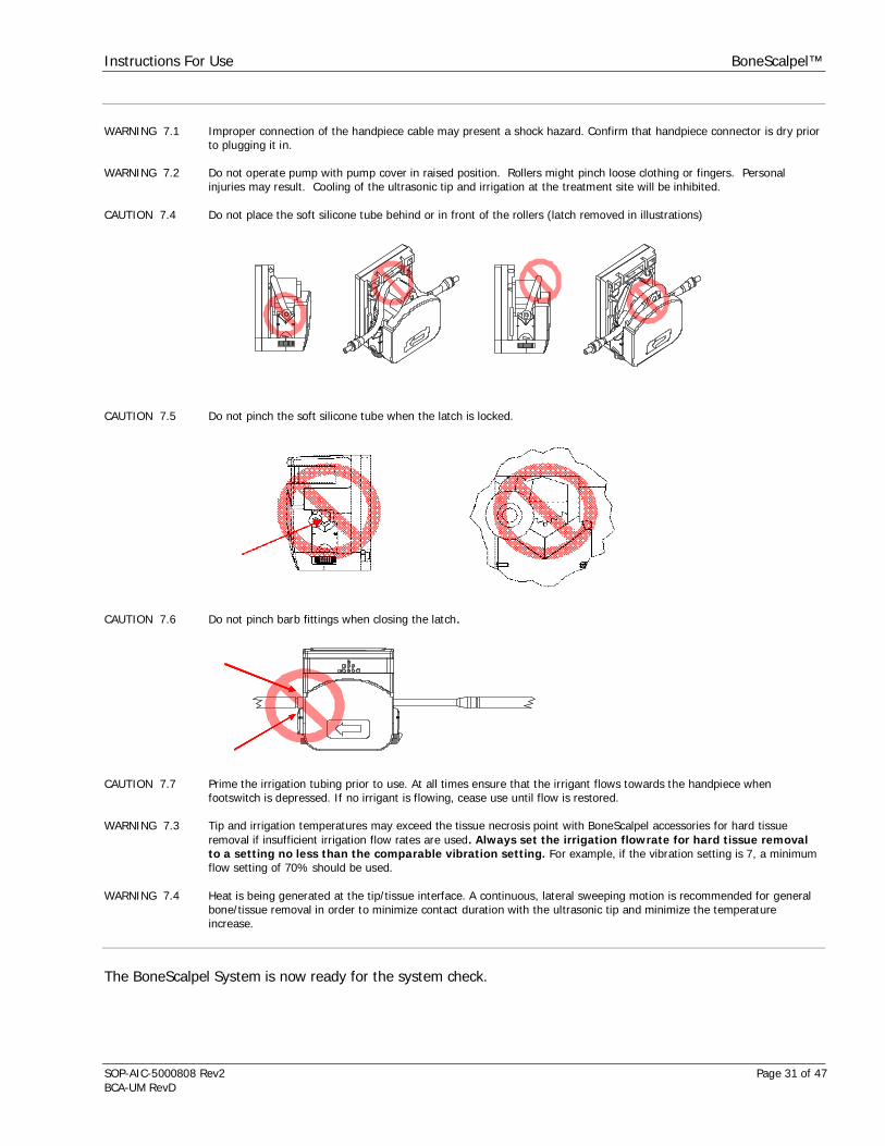
WARNING 7.1 Improper connection of the handpiece cable may present a shock hazard. Confirm that handpiece connector is dry priorto plugging it in.
WARNING 7.2 Do not operate pump with pump cover in raised position. Rollers might pinch loose clothing or fingers. Personalinjuries may result. Cooling of the ultrasonic tip and irrigation at the treatment site will be inhibited.
CAUTION 7.4 Do not place the soft silicone tube behind or in front of the rollers (latch removed in illustrations)
CAUTION 7.5 Do not pinch the soft silicone tube when the latch is locked.
CAUTION 7.6 Do not pinch barb fittings when closing the latch.
CAUTION 7.7 Prime the irrigation tubing prior to use. At all times ensure that the irrigant flows towards the handpiece whenfootswitch is depressed. If no irrigant is flowing, cease use until flow is restored.
WARNING 7.3 Tip and irrigation temperatures may exceed the tissue necrosis point with BoneScalpel accessories for hard tissueremoval if insufficient irrigation flow rates are used. Always set the irrigation flowrate for hard tissue removalto a setting no less than the comparable vibration setting. For example, if the vibration setting is 7, a minimumflow setting of 70% should be used.
WARNING 7.4 Heat is being generated at the tip/tissue interface. A continuous, lateral sweeping motion is recommended for generalbone/tissue removal in order to minimize contact duration with the ultrasonic tip and minimize the temperatureincrease.
The BoneScalpel System is now ready for the system check.
Instructions For Use BoneScalpel™
SOP-AIC-5000808 Rev2 Page 32 of 47BCA-UM RevD
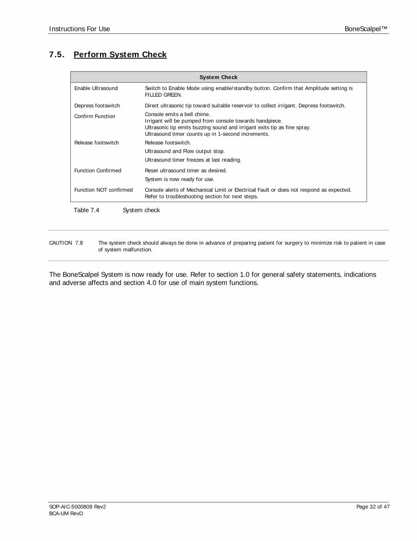
7.5. Perform System Check
System Check
Enable Ultrasound Switch to Enable Mode using enable/standby button. Confirm that Amplitude setting isFILLED GREEN.
Depress footswitch Direct ultrasonic tip toward suitable reservoir to collect irrigant. Depress footswitch.
Confirm Function Console emits a bell chime.Irrigant will be pumped from console towards handpiece.Ultrasonic tip emits buzzing sound and irrigant exits tip as fine spray.Ultrasound timer counts up in 1-second increments.
Release footswitch Release footswitch.
Ultrasound and Flow output stop.
Ultrasound timer freezes at last reading.
Function Confirmed Reset ultrasound timer as desired.
System is now ready for use.
Function NOT confirmed Console alerts of Mechanical Limit or Electrical Fault or does not respond as expected.Refer to troubleshooting section for next steps.
Table 7.4 System check
CAUTION 7.8 The system check should always be done in advance of preparing patient for surgery to minimize risk to patient in caseof system malfunction.
The BoneScalpel System is now ready for use. Refer to section 1.0 for general safety statements, indicationsand adverse affects and section 4.0 for use of main system functions.

Instructions For Use BoneScalpel™
SOP-AIC-5000808 Rev2 Page 33 of 47BCA-UM RevD
8. Handpiece Assembly And DisassemblyThe BoneScalpel Ultrasonic Surgical System can accommodate different tip configurations to perform hardtissue applications.
8.1. Handpiece AssemblyPerform an inspection of handpiece and all components prior assembly.
Handpiece Inspection
InspectHandpiece
Inspect the black handpiece housing for any visual cracks. Inspect the front metallic portionprobe for surface damage like nicks, gouges and cracks. Replace if damaged.
InspectMating Surface
Inspect mating face of handpiece to verify that it is clean and dry.
Table 8.1 Handpiece inspection
CAUTION 8.1 Ensure all connections and mating surfaces of handpiece, extension and ultrasonic tip are clean and dry beforeassembly.
CAUTION 7.2 All items intended for use in the sterile field must be cleaned and sterilized as per indicated instructions before eachclinical use.
CAUTION 7.3 The disposable items are intended for one procedure only (single use). Do not attempt to reuse or re-sterilize.
NOTE 8.1 The handpiece must be placed into the counter wrench. Do not attempt to tighten or loosen handpiece components byholding the handpiece case or endcap. Always use the T-wrench wrench when tightening or un-tightening the tip or anextension. Never apply a pipe or strap wrench to the handpiece case. Do not over-tighten the tip or the extension.
NOTE 8.2 Always tighten or un-tighten the probe cover by hand and without using any wrenches. Do not over-tighten the probecover.
NOTE 8.3 Always hold the handpiece at its metallic endcap when tightening or un-tightening the irrigation tubing. Always tightenor un-tighten the irrigation tubing by hand and without using any wrenches. Do not over-tighten the tubing connector.
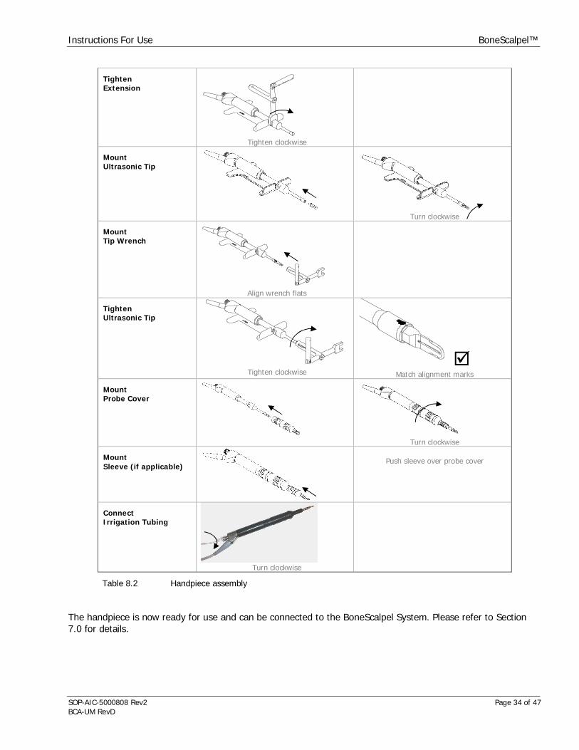
Handpiece Assembly
MountHandpiece Wrench
Align wrench flats
MountExtension
Turn clockwise
Instructions For Use BoneScalpel™
SOP-AIC-5000808 Rev2 Page 34 of 47BCA-UM RevD
TightenExtension
Tighten clockwise
MountUltrasonic Tip
Turn clockwise
MountTip Wrench
Align wrench flats
TightenUltrasonic Tip
Tighten clockwise Match alignment marks
MountProbe Cover
Turn clockwise
MountSleeve (if applicable)
Push sleeve over probe cover
ConnectIrrigation Tubing
Turn clockwise
Table 8.2 Handpiece assembly
The handpiece is now ready for use and can be connected to the BoneScalpel System. Please refer to Section7.0 for details.

Instructions For Use BoneScalpel™
SOP-AIC-5000808 Rev2 Page 35 of 47BCA-UM RevD
Figure 8.1 Fully assembled handpiece
If desired, mount suitable sterile cable clips or sterile adhesive tape strips to attach irrigation tubing tohandpiece cable.
8.2. Handpiece Disassembly
WARNING 8.1 Remove probe cover, ultrasonic tip and extension from the handpiece prior to cleaning and/or sterilization; otherwiseproper cleaning/sterilization may be inhibited.
NOTE 8.1 The handpiece must be placed into the counter wrench. Do not attempt to tighten or loosen handpiece components byholding the handpiece case or endcap. Always use the T-wrench wrench when tightening or un-tightening the tip or anextension. Never apply a pipe or strap wrench to the handpiece case. Do not over-tighten the tip or the extension.
NOTE 8.2 Always tighten or un-tighten the probe cover by hand and without using any wrenches. Do not over-tighten the probecover.
NOTE 8.3 Always hold the handpiece at its metallic endcap when tightening or un-tightening the irrigation tubing. Always tightenor un-tighten the irrigation tubing by hand and without using any wrenches. Do not over-tighten the tubing connector.
Handpiece Disassembly
DisconnectIrrigation Tubing
Turn counter-clockwise
RemoveSheath
Pull sheath from probe cover

Instructions For Use BoneScalpel™
SOP-AIC-5000808 Rev2 Page 36 of 47BCA-UM RevD
RemoveProbe Cover
Turn counter-clockwise
MountHandpiece Wrench
Align wrench flats
MountTip Wrench
RemoveUltrasonic Tip
Table 8.3 Handpiece disassembly
Instructions For Use BoneScalpel™
SOP-AIC-5000808 Rev2 Page 37 of 47BCA-UM RevD
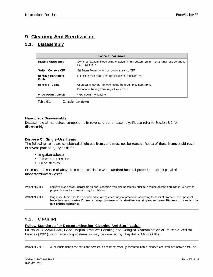
9. Cleaning And Sterilization9.1. Disassembly
Console Tear-down
Disable Ultrasound Switch to Standby Mode using enable/standby button. Confirm that Amplitude setting isHOLLOW GREY.
Switch Console OFF Set Mains Power switch on console rear to OFF.
Remove HandpieceCable
Pull cable connector from receptacle on console front.
Remove Tubing Open pump cover. Remove tubing from pump compartment.
Disconnect tubing from irrigant container.
Wipe Down Console Wipe down the console.
Table 9.1 Console tear-down
Handpiece DisassemblyDisassemble all handpiece components in reverse order of assembly. Please refer to Section 8.2 fordisassembly.
Dispose Of Single-Use ItemsThe following items are considered single use items and must not be reused. Reuse of these items could resultin severe patient injury or death.
Irrigation tubesetTips with extensionsSilicon sleeves
Once used, dispose of above items in accordance with standard hospital procedures for disposal ofbiocontaminated wastes.
WARNING 8.1 Remove probe cover, ultrasonic tip and extension from the handpiece prior to cleaning and/or sterilization; otherwiseproper cleaning/sterilization may be inhibited.
WARNING 9.1 Single-use items should be discarded following each surgical procedure according to hospital protocol for disposal ofbiocontaminated wastes. Do not attempt to reuse or re-sterilize any single-use items. Dispose ultrasonic tipsin a sharps container.
9.2. CleaningFollow Standards For Decontamination, Cleaning And SterilizationFollow ANSI/AAMI ST35, Good Hospital Practice: Handling and Biological Contamination of Reusable MedicalDevices (1991), or other such guidelines as may be directed by Hospital or Clinic GHP’s.
WARNING 9.2 All reusable handpiece parts and accessories must be properly decontaminated, cleaned and sterilized before each use
Instructions For Use BoneScalpel™
SOP-AIC-5000808 Rev2 Page 38 of 47BCA-UM RevD
as per instructions contained in this manual. Failure to do so may lead to infections, which can ultimately cause patientdeath.
WARNING 9.3 The manufacturer has validated all cleaning and sterilization cycles given in this manual. It is highly recommended thatthe procedures given in this manual for cleaning and sterilizing the BoneScalpel System and related accessories befollowed. It is the responsibility of the user of this device or any accessories used with it to validate procedures forcleaning and/or sterilization if they differ from the procedures as outlined in this manual.
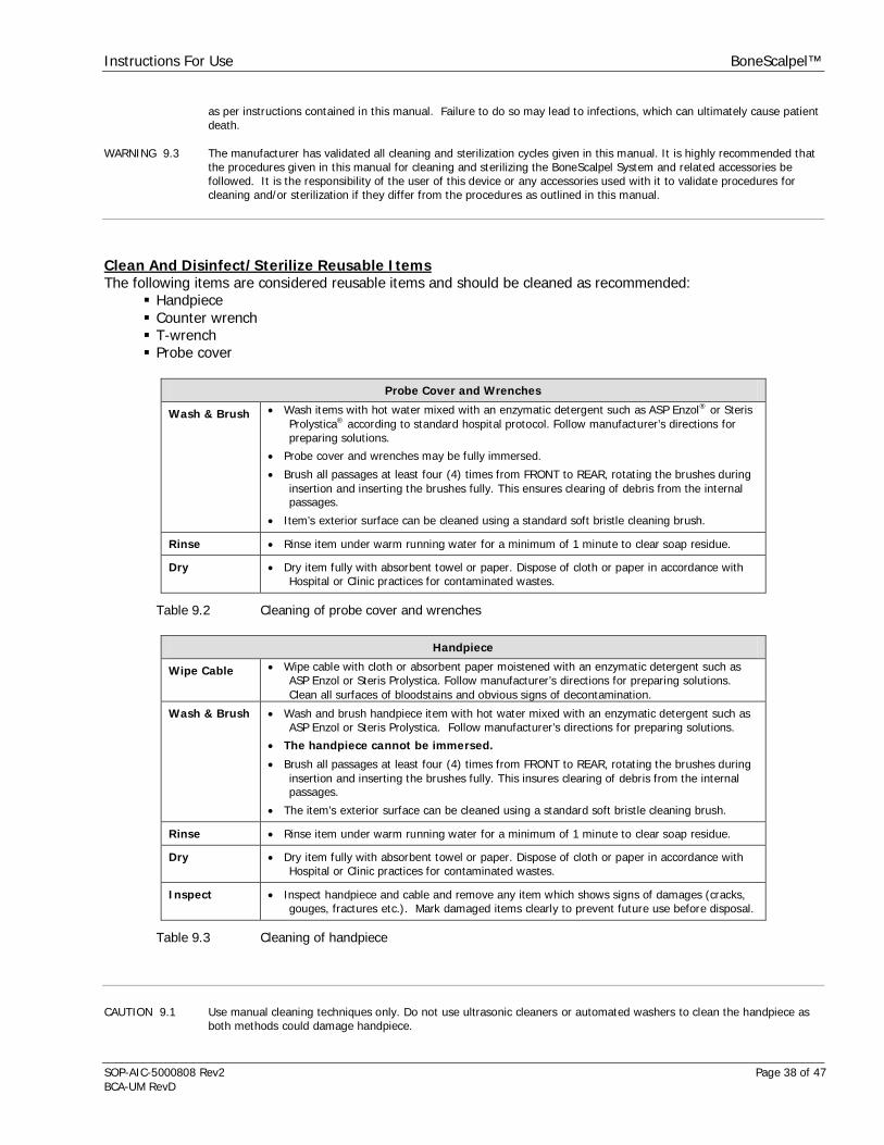
Clean And Disinfect/Sterilize Reusable ItemsThe following items are considered reusable items and should be cleaned as recommended:
HandpieceCounter wrenchT-wrenchProbe cover
Probe Cover and Wrenches
Wash & Brush Wash items with hot water mixed with an enzymatic detergent such as ASP Enzol® or SterisProlystica® according to standard hospital protocol. Follow manufacturer’s directions forpreparing solutions.
Probe cover and wrenches may be fully immersed.
Brush all passages at least four (4) times from FRONT to REAR, rotating the brushes duringinsertion and inserting the brushes fully. This ensures clearing of debris from the internalpassages.
Item’s exterior surface can be cleaned using a standard soft bristle cleaning brush.
Rinse Rinse item under warm running water for a minimum of 1 minute to clear soap residue.
Dry Dry item fully with absorbent towel or paper. Dispose of cloth or paper in accordance withHospital or Clinic practices for contaminated wastes.
Table 9.2 Cleaning of probe cover and wrenches
Handpiece
Wipe Cable Wipe cable with cloth or absorbent paper moistened with an enzymatic detergent such asASP Enzol or Steris Prolystica. Follow manufacturer’s directions for preparing solutions.Clean all surfaces of bloodstains and obvious signs of decontamination.
Wash & Brush Wash and brush handpiece item with hot water mixed with an enzymatic detergent such asASP Enzol or Steris Prolystica. Follow manufacturer’s directions for preparing solutions.
The handpiece cannot be immersed.
Brush all passages at least four (4) times from FRONT to REAR, rotating the brushes duringinsertion and inserting the brushes fully. This insures clearing of debris from the internalpassages.
The item’s exterior surface can be cleaned using a standard soft bristle cleaning brush.
Rinse Rinse item under warm running water for a minimum of 1 minute to clear soap residue.
Dry Dry item fully with absorbent towel or paper. Dispose of cloth or paper in accordance withHospital or Clinic practices for contaminated wastes.
Inspect Inspect handpiece and cable and remove any item which shows signs of damages (cracks,gouges, fractures etc.). Mark damaged items clearly to prevent future use before disposal.
Table 9.3 Cleaning of handpiece
CAUTION 9.1 Use manual cleaning techniques only. Do not use ultrasonic cleaners or automated washers to clean the handpiece asboth methods could damage handpiece.

Instructions For Use BoneScalpel™
SOP-AIC-5000808 Rev2 Page 39 of 47BCA-UM RevD
CAUTION 9.2 Be certain to clear debris from all internal passages by brushing. Failure to do so may hinder sterilization of unitsduring autoclaving.
CAUTION 9.3 Do not immerse ultrasonic console, handpiece, irrigation pump, remote footswitch or electric cables. These items arenot sealed against liquids and damage to equipment will result.
Console and Footswitch
Wipe Surfaces Wipe footswitch and console, including irrigation unit, with cloth or absorbent papermoistened with an enzymatic detergent such as ASP Enzol® or Steris Prolystica®. Followmanufacturer’s directions for preparing solutions. Clean all surfaces of bloodstains andobvious signs of decontamination.
Dispose of cloth or paper with contaminated waste.
Table 9.4 Cleaning of console and footswitch
9.3. Sterilizing By Steam Autoclave
Reusable, autoclavable Components
MC632 Handpiece
MC628 T-Wrench
MC637 Handpiece/Counter Wrench
MC631 Probe Cover for hard tissue applications
MC638 Brush Set, Small
MC639 Brush Set, Large
Table 9.5 Autoclavable components
Validated Steam Sterilization Cycles
Sterilizer Type Pre-Vacuum at 132 °C | 270 °F Gravity at 134 °C | 273 °F
Preconditioning pulses 3 None
Minimum Temperature 132 °C | 270 °F 134 °C | 273 °F
Full Cycle Time 8 min 20 min
Minimum Dry Time 5 min 5 min
Cooling Time Allow items to cool gradually to room temperature prior use.
Sample configuration Wrapped Wrapped
Table 9.6 Steam sterilization cycles
NOTE 9.1 Allow reusable, autoclavable items to gradually return to room temperature after steam sterilization and prior to usage.
9.4. Expected Life, Reusable ComponentsAll handpiece components need to examined regularly, prior each use and be replaced if damaged.
Instructions For Use BoneScalpel™
SOP-AIC-5000808 Rev2 Page 40 of 47BCA-UM RevD
The estimated sterilization life of handpiece components is listed below. All sterilization life estimates areapproximate and may be affected by rough handling, damage, wear due to vigorous cleaning, etc.
Estimated Sterilization Life
Item Number Of SteamSterilization Cycles
Handpiece with attached cable > 200 cycles
Probe cover > 300 cycles
Wrenches:
Handpiece/counter wrench and T-wrench
> 300 cycles
Table 9.7 Estimated re-use life
NOTE 9.2 The reuse life given takes into account wear and tear due to cleaning and sterilization only. Damage or wear caused byactual use in treatments will affect life of components.
NOTE 9.1 Allow reusable, autoclavable items to gradually return to room temperature after steam sterilization and prior to usage.
9.5. Deviations From Decontamination, Cleaning And Sterilization InstructionsThe manufacturer has validated all cleaning, disinfection and sterilization cycles given in this manual. It is highlyrecommended that the procedures given in this manual for cleaning and sterilizing the BoneScalpel System andrelated accessories be followed. It is the responsibility of the user of this device or any accessories used with itto validate procedures for cleaning and/or sterilization if they differ from the procedures as outlined in thismanual.
Technical AssistanceShould the user wish further information or instructions regarding any aspect of cleaning or sterilizingprocedures, please contact Aesculap USA or an Authorized Representative.
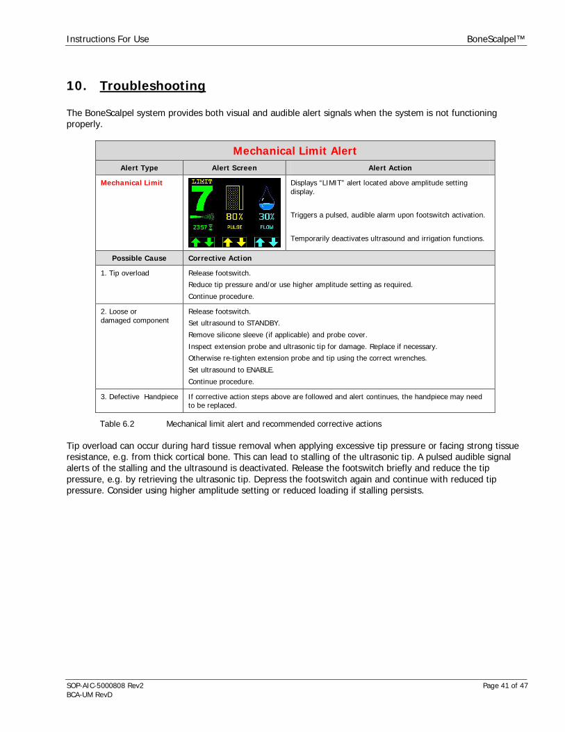
Instructions For Use BoneScalpel™
SOP-AIC-5000808 Rev2 Page 41 of 47BCA-UM RevD
10. Troubleshooting
The BoneScalpel system provides both visual and audible alert signals when the system is not functioningproperly.
Mechanical Limit AlertAlert Type Alert Screen Alert Action
Mechanical Limit Displays “LIMIT” alert located above amplitude settingdisplay.
Triggers a pulsed, audible alarm upon footswitch activation.
Temporarily deactivates ultrasound and irrigation functions.
Possible Cause Corrective Action
1. Tip overload Release footswitch.
Reduce tip pressure and/or use higher amplitude setting as required.
Continue procedure.
2. Loose ordamaged component
Release footswitch.
Set ultrasound to STANDBY.
Remove silicone sleeve (if applicable) and probe cover.
Inspect extension probe and ultrasonic tip for damage. Replace if necessary.
Otherwise re-tighten extension probe and tip using the correct wrenches.
Set ultrasound to ENABLE.
Continue procedure.
3. Defective Handpiece If corrective action steps above are followed and alert continues, the handpiece may needto be replaced.
Table 6.2 Mechanical limit alert and recommended corrective actions
Tip overload can occur during hard tissue removal when applying excessive tip pressure or facing strong tissueresistance, e.g. from thick cortical bone. This can lead to stalling of the ultrasonic tip. A pulsed audible signalalerts of the stalling and the ultrasound is deactivated. Release the footswitch briefly and reduce the tippressure, e.g. by retrieving the ultrasonic tip. Depress the footswitch again and continue with reduced tippressure. Consider using higher amplitude setting or reduced loading if stalling persists.

Instructions For Use BoneScalpel™
SOP-AIC-5000808 Rev2 Page 42 of 47BCA-UM RevD
Electrical Fault AlertAlert Type Alert Screen Alert Action
Electrical Fault Displays Electrical Fault Screen.
Triggers steady audible alarm.
Permanently deactivates ultrasound and irrigation. Requiresrecycling of mains power switch to re-set.
Possible Cause Corrective Action
1. Handpiece notconnected
Turn console OFF.
Check handpiece cable connection.
Restart console.
2. DefectiveHandpiece
Turn console OFF.
Replace handpiece and restart console.
If problem persists replace console.
3. Defective console Turn console OFF.
Replace console.
Table 6.3 Electrical fault alert and recommended corrective actions
WARNING 6.1 Immediately suspend operation if Electrical Fault appears on display and/or an Electrical Fault audible alarm sounds.Remove ultrasonic tip from surgical site. Turn Mains Power OFF. Do not touch any metallic parts of handpiece,extension, ultrasonic tip or generator while fault is indicated.
WARNING 1.4 Proper system grounding can only be ensured when an approved, hospital-grade receptacle and matching power cordare used. Install plug and receptacles as per local regulations before operating the unit. Power cord, plug andreceptacle should be examined to verify that they are in good working condition before connecting the console. Neverpull on the power cord to remove it from the receptacle.
WARNING 10.1 If a Mains Power fuse fails after replacement when the unit is reactivated, discontinue use of the device and contact anauthorized Aesculap USA representative.
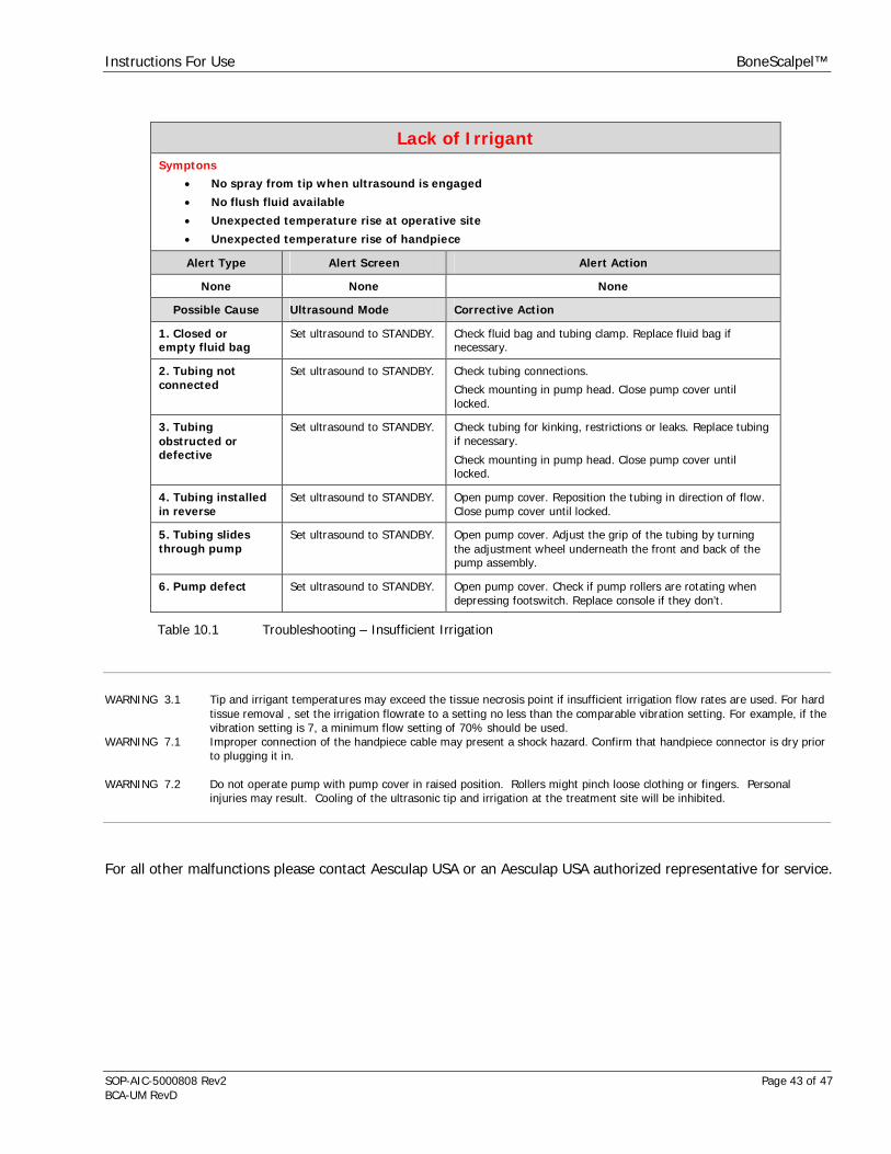
Instructions For Use BoneScalpel™
SOP-AIC-5000808 Rev2 Page 43 of 47BCA-UM RevD
Lack of IrrigantSymptons
No spray from tip when ultrasound is engaged
No flush fluid available
Unexpected temperature rise at operative site
Unexpected temperature rise of handpiece
Alert Type Alert Screen Alert Action
None None None
Possible Cause Ultrasound Mode Corrective Action
1. Closed orempty fluid bag
Set ultrasound to STANDBY. Check fluid bag and tubing clamp. Replace fluid bag ifnecessary.
2. Tubing notconnected
Set ultrasound to STANDBY. Check tubing connections.
Check mounting in pump head. Close pump cover untillocked.
3. Tubingobstructed ordefective
Set ultrasound to STANDBY. Check tubing for kinking, restrictions or leaks. Replace tubingif necessary.
Check mounting in pump head. Close pump cover untillocked.
4. Tubing installedin reverse
Set ultrasound to STANDBY. Open pump cover. Reposition the tubing in direction of flow.Close pump cover until locked.
5. Tubing slidesthrough pump
Set ultrasound to STANDBY. Open pump cover. Adjust the grip of the tubing by turningthe adjustment wheel underneath the front and back of thepump assembly.
6. Pump defect Set ultrasound to STANDBY. Open pump cover. Check if pump rollers are rotating whendepressing footswitch. Replace console if they don’t.
Table 10.1 Troubleshooting – Insufficient Irrigation
WARNING 3.1 Tip and irrigant temperatures may exceed the tissue necrosis point if insufficient irrigation flow rates are used. For hardtissue removal , set the irrigation flowrate to a setting no less than the comparable vibration setting. For example, if thevibration setting is 7, a minimum flow setting of 70% should be used.
WARNING 7.1 Improper connection of the handpiece cable may present a shock hazard. Confirm that handpiece connector is dry priorto plugging it in.
WARNING 7.2 Do not operate pump with pump cover in raised position. Rollers might pinch loose clothing or fingers. Personalinjuries may result. Cooling of the ultrasonic tip and irrigation at the treatment site will be inhibited.
For all other malfunctions please contact Aesculap USA or an Aesculap USA authorized representative for service.
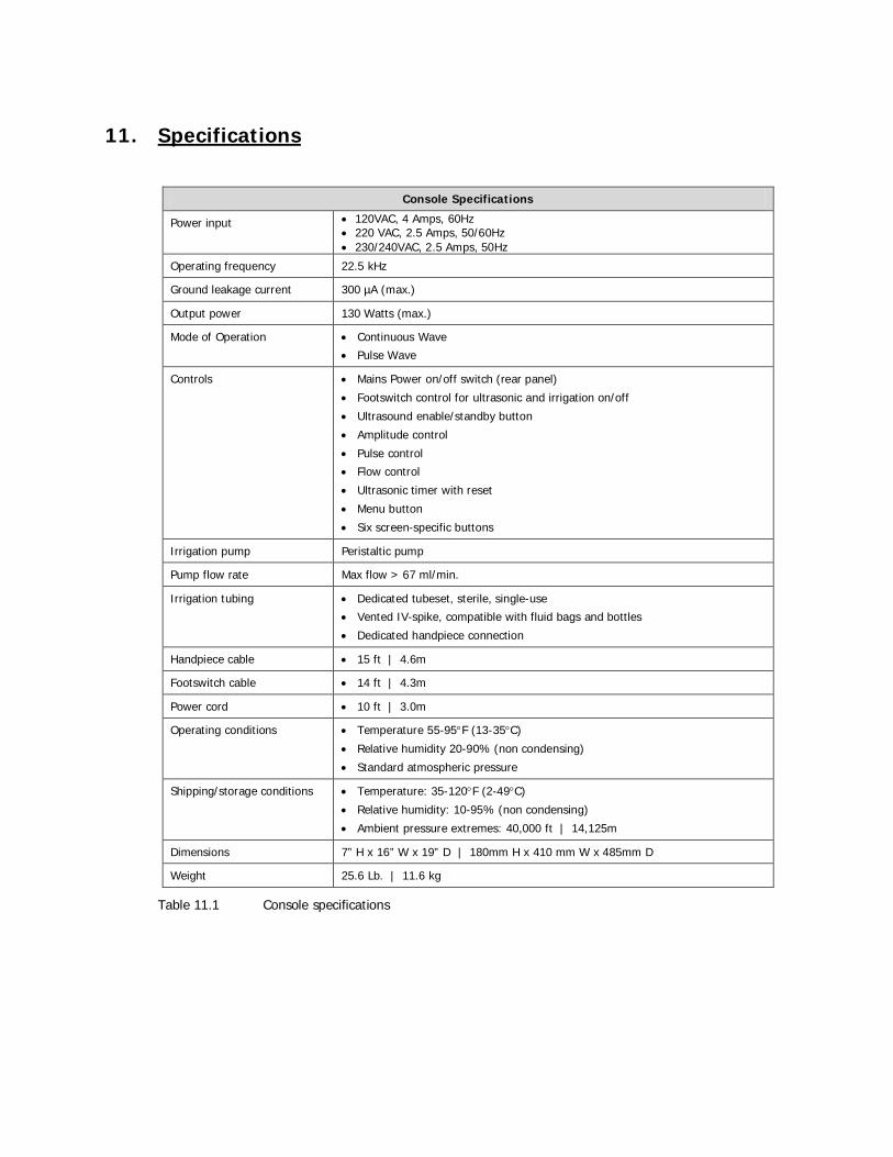
11. Specifications
Console Specifications
Power input 120VAC, 4 Amps, 60Hz220 VAC, 2.5 Amps, 50/60Hz230/240VAC, 2.5 Amps, 50Hz
Operating frequency 22.5 kHz
Ground leakage current 300 µA (max.)
Output power 130 Watts (max.)
Mode of Operation Continuous Wave
Pulse Wave
Controls Mains Power on/off switch (rear panel)
Footswitch control for ultrasonic and irrigation on/off
Ultrasound enable/standby button
Amplitude control
Pulse control
Flow control
Ultrasonic timer with reset
Menu button
Six screen-specific buttons
Irrigation pump Peristaltic pump
Pump flow rate Max flow > 67 ml/min.
Irrigation tubing Dedicated tubeset, sterile, single-use
Vented IV-spike, compatible with fluid bags and bottles
Dedicated handpiece connection
Handpiece cable 15 ft | 4.6m
Footswitch cable 14 ft | 4.3m
Power cord 10 ft | 3.0m
Operating conditions Temperature 55-95 F (13-35 C)
Relative humidity 20-90% (non condensing)
Standard atmospheric pressure
Shipping/storage conditions Temperature: 35-120 F (2-49 C)
Relative humidity: 10-95% (non condensing)
Ambient pressure extremes: 40,000 ft | 14,125m
Dimensions 7” H x 16” W x 19” D | 180mm H x 410 mm W x 485mm D
Weight 25.6 Lb. | 11.6 kg
Table 11.1 Console specifications
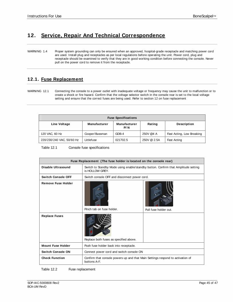
Instructions For Use BoneScalpel™
SOP-AIC-5000808 Rev2 Page 45 of 47BCA-UM RevD
12. Service, Repair And Technical Correspondence
WARNING 1.4 Proper system grounding can only be ensured when an approved, hospital-grade receptacle and matching power cordare used. Install plug and receptacles as per local regulations before operating the unit. Power cord, plug andreceptacle should be examined to verify that they are in good working condition before connecting the console. Neverpull on the power cord to remove it from the receptacle.
12.1. Fuse Replacement
WARNING 12.1 Connecting the console to a power outlet with inadequate voltage or frequency may cause the unit to malfunction or tocreate a shock or fire hazard. Confirm that the voltage selector switch in the console rear is set to the local voltagesetting and ensure that the correct fuses are being used. Refer to section 12 on fuse replacement
Fuse Specifications
Line Voltage Manufacturer ManufacturerP/N
Rating Description
120 VAC, 60 Hz Cooper/Bussman GDB-4 250V @4 A Fast Acting, Low Breaking
220/230/240 VAC, 50/60 Hz Littlefuse 021702.5 250V @ 2.5A Fast Acting
Table 12.1 Console fuse specifications
Fuse Replacement (The fuse holder is located on the console rear)
Disable Ultrasound Switch to Standby Mode using enable/standby button. Confirm that Amplitude settingis HOLLOW GREY.
Switch Console OFF Switch console OFF and disconnect power cord.
Remove Fuse Holder
Pinch tab on fuse holder. Pull fuse holder out.
Replace Fuses
Replace both fuses as specified above.
Mount Fuse Holder Push fuse holder back into receptacle.
Switch Console ON Connect power cord and switch console ON
Check Function Confirm that console powers up and that Main Settings respond to activation ofbuttons A-F.
Table 12.2 Fuse replacement
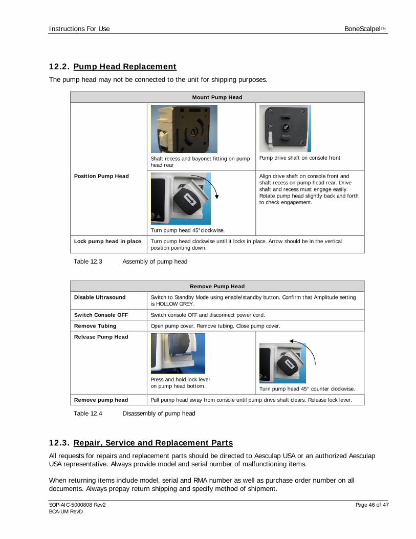
Instructions For Use BoneScalpel™
SOP-AIC-5000808 Rev2 Page 46 of 47BCA-UM RevD
12.2. Pump Head ReplacementThe pump head may not be connected to the unit for shipping purposes.
Mount Pump Head
Shaft recess and bayonet fitting on pumphead rear
Pump drive shaft on console front
Position Pump Head
Turn pump head 45°clockwise.
Align drive shaft on console front andshaft recess on pump head rear. Driveshaft and recess must engage easily.Rotate pump head slightly back and forthto check engagement.
Lock pump head in place Turn pump head clockwise until it locks in place. Arrow should be in the verticalposition pointing down.
Table 12.3 Assembly of pump head
Remove Pump Head
Disable Ultrasound Switch to Standby Mode using enable/standby button. Confirm that Amplitude settingis HOLLOW GREY.
Switch Console OFF Switch console OFF and disconnect power cord.
Remove Tubing Open pump cover. Remove tubing. Close pump cover.
Release Pump Head
Press and hold lock leveron pump head bottom. Turn pump head 45° counter clockwise.
Remove pump head Pull pump head away from console until pump drive shaft clears. Release lock lever.
Table 12.4 Disassembly of pump head
12.3. Repair, Service and Replacement PartsAll requests for repairs and replacement parts should be directed to Aesculap USA or an authorized AesculapUSA representative. Always provide model and serial number of malfunctioning items.
When returning items include model, serial and RMA number as well as purchase order number on alldocuments. Always prepay return shipping and specify method of shipment.

Instructions For Use BoneScalpel™
SOP-AIC-5000808 Rev2 Page 47 of 47BCA-UM RevD
CAUTION 12.1 Use only genuine replacement parts from Aesculap. Use of parts furnished by other sources may result in patient oroperator injury or system malfunction and will void any applicable warranty.
CAUTION 12.2 Before using loose packing materials, such as foam pellets, shredded paper or similar, be sure to wrap thecomponent(s) separately in plastic bags, film or other protective wrapping.
12.4. Important Notice
Please contact Aesculap USA with any questions regarding the specifications, use, sterilization, limitations ormaintenance of the BoneScalpel System:
Aesculap, Inc.Web www.aesculapusa.comEmail [email protected] +1-800-258-1946Customer Service: 1-800-282-9000Technical Service: 1-800-214-3392Address 3773 Corporate Parkway
Center Valley, PA 18034U.S.A.
By returning any material to Aesculap USA the customer or the customer's agent must certify thatany and all materials so returned are or have been rendered free of any hazardous or noxiousmatter or radioactive contamination and are safe for handling under normal repair shop conditions.
Do not return any material for which such certification cannot be made without prior approval fromAesculap USA.
The correct return address should read as follows:
Aesculap, Inc.615 Lambert PointeRMA#: ___________Hazelwood, MO 63042Phone: 1-800-258-1946U.S.A.
Distributed in the U.S.A. by: Aesculap, Inc.3773 Corporate ParkwayCenter Valley, PA 18034Phone: 1-800-258-1946
Manufactured by: Misonix, Inc.1938 New HighwayFarmingdale, NY 11735Phone: 1-800-694-9612

Instructions For Use BoneScalpel™
SOP-AIC-5000808 Rev2 Page 48 of 47BCA-UM RevD

Instructions For Use BoneScalpel™
SOP-AIC-5000808 Rev2 Page 49 of 47BCA-UM RevD
Customer Service: 1.800.282.9000, Technical Service: 1.800.214.33923773 Corporate Parkway, Center Valley, PA 18034, U.S.A.