Embed Size (px)
Citation preview

instructions for start-up
notice de mise en service
betriebsanleitung
manual de puesta en marcha
integralbus
profibus dp for integral+profibus dp pour integral+
profibus dp für integral-plusprofibus dp para integral+af
d_nr
1148
rev
B
3
1 INTRODUCTION Page 42 TECHNICAL SPECIFICATIONS Page 53 PROFIBUS INTERFACE Page 5 3.1 HARDWARE DESCRIPTION Page 5 3.2 SET-UP Page 6 3.3 POSITION SIGNAL OPTIONS Page 7 3.3.1 FEEDBACK POTENTIOMETER OPTION Page 7 3.3.2 ACTUATOR WITH POSITIONER OPTION POSIGAM+ OR MODUGAM+ Page 74 CABLE TYPE Page 85 BUS CONNECTION Page 86 PROFIBUS DP ARCHITECTURE Page 87 COMMANDS AND SIGNALLING Page 10 7.1 COMMANDS Page 10 7.2 SIGNALLING Page 12
1 INTRODUCTION Page 142 CARACTERISTIQUES TECHNIQUES Page 153 INTERFACE PROFIBUS DP Page 15 3.1 DESCRIPTION PHYSIQUE Page 15 3.2 CONFIGURATION Page 16 3.3 OPTION SIGNAL DE POSITION Page 17 3.3.1 SERVOMOTEUR AVEC L’OPTION POTENTIOMETRE DE RECOPIE Page 17 3.3.2 SERVOMOTEUR AVEC L’OPTION POSITIONNEUR POSIGAM+ OU MODUGAM+ Page 174 CABLE DE BUS Page 185 RACCORDEMENT DU BUS Page 186 ARCHITECTURE DE PROFIBUS DP Page 187 COMMANDE ET SIGNALISATION DES VANNES Page 20 7.1 COMMANDES DES VANNES Page 20 7.2 SIGNALISATION DES VANNES Page 22
1 INTRODUCCIÓN Página 342 CARACTERÍSTICAS TÉCNICOS Página 353 INTERFACE PROFIBUS DP Página 35 3.1 DESCRIPCIÓN FÍSICA Página 35 3.2 CONFIGURACIÓN Página 36 3.3 OPCIÓN SEÑAL DE POSICIÓN Página 37 3.3.1 SERVOMOTOR CON LA OPCIÓN DE POTENCIÓMETRO DE COPIA Página 37 3.3.2 SERVOMOTOR CON LA OPCIÓN DE POSICIONADOR POSIGAM + O MODUGAM+ Página 374 CABLE DE BUS Página 385 ENLACE DEL BUS Página 386 PROFIBUS DP-ARCHITEKTUR Página 387 CONTROL Y SEÑALIZACIÓN DE SERVOMOTORES Página 40 7.1 CONTROL DE LOS SERVOMOTORES Página 40 7.2 SEÑALIZACIÓN DE LOS SERVOMOTORES Página 42
1 EINLEITUNG Seite 242 TECHNISCHE DATEN Seite 253 PROFIBUS DP-SCHNITTSTELLE Seite 25 3.1 HARDWAREBESCHREIBUNG Seite 25 3.2 KONFIGURATION Seite 26 3.3 OPTION POSITIONSSIGNAL Seite 27 3.3.1 STELLANTRIEB MIT DER OPTION POSITIONSRÜCKMELDUNGS-POTENTIOMETER Seite 27 3.3.2 STELLANTRIEB MIT DER OPTION POSITIONIERER POSIGAM+ ODER MODUGAM+ Seite 274 FELDBUSKABEL Seite 285 FELDBUSANSCHLUSS Seite 286 PROFIBUS DP-ARCHITEKTUR Seite 287 STEUERUNG UND MELDUNGEN DER ARMATUREN Seite 30 7.1 STEUERUNG DER ARMATUREN Seite 30 7.2 MELDUNGEN DER ARMATUREN Seite 3
CONTENTS
SOMMAIRE ÍNDICE
INHALT
4 5
1 INTRODUCTION
Profibus DP is an industrial fieldbus which allows to connect actuators and other devices (sensors,…) to a Digital Control System (DCS). Many actuators and other devices can be connected on a single fieldbus line provided they are all equipped with a compatible Profibus interface. The Profibus DP interface described in this document has been specially designed for the Bernard actuators with INTEGRAL+, POSIGAM+ or MODUGAM+ controls. As far as actuators with INTELLI+ controls are concerned, please refer to the Profibus DPV1 for INTELLI+ instructions for start-up.
Control box with inside Profibus DP interface could be supplied to connect other equipment.
Redundant communication
The redundant version is specially interesting to ensure a communication continuity even if one line disrupted or if one interface board is out of order for any reason.In case of a redundant bus, the DCS must be able to manage 2 fieldbus lines. In case of failure along the main line, the DCS can still communicate through the auxiliary line. According to the fieldbus version required an INTEGRALBUS, single or redundant line, may equip the actuator.
2 TECHNICAL SPECIFICATIONS
- The PROFIBUS-DP slave board can be controlled by a master PROFIBUS-DP board : PLC, PC, DCS and other interface boards…from various suppliers.
- Hardware communication standard : RS 485.- Automatic speed selection : 9.6k … 1.5Mbauds.- Actuators addresses from 1 to 99- Maximum number of actuators by line : 31 (up to 99 with repeaters)- 2 communication status leds and 1 power supply status Led.- Approved by PNO (Profibus Nutzer Organisation).- CE conformity.- GSD file name : Single line LBVS 099.GSD Redundant line LBVR 099.GSD- Fieldbus is electrically totally isolated from the actuator circuitry. In case of a redundant version,
each input is electrically isolated from the actuator circuitry and are isolated from each other.- A loss of the actuator power supply do not lead to a fieldbus disruption.- Temperature working range is the same as the actuator one.
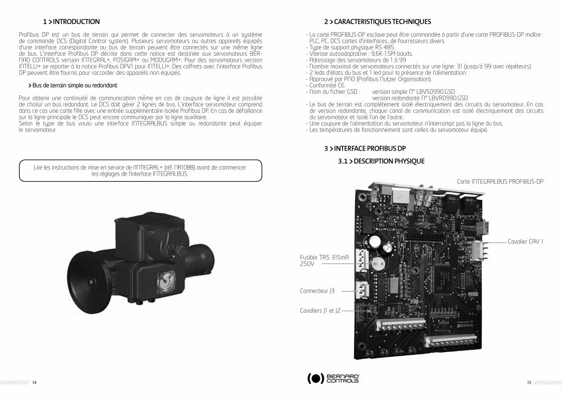
3 PROFIBUS DP INTERFACE
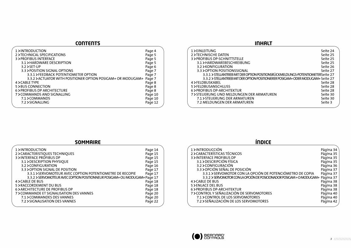
3.1 HARDwARE DESCRIPTION
Please make sure to get and read the INTEGRAL+ instructions for start-up (ref.NR1088) prior going further with the setting of the Integralbus interface.
TR5 315mA 250VFuse F1
Connector J3
Jumper CAV 1
PROFIBUS-DP ‘’INTEGRALBUS’’ board
Jumpers J1 & J2
6 7
Access to the board (for actuator address setting and end of line resistor set-up) :Open the button plate for weatherproof model and open electronic box for Explosionproof model.
Warning : Explosionproof versionsPlease refer to the specific instructions ref. TMS1132 relative to the explosionproof actuators prior to opening the cover.
Waterproof Explosionproof
3.2 SET-UP
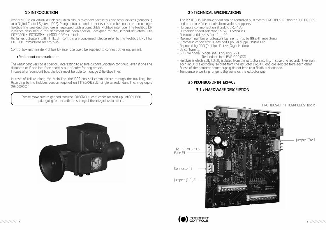
INTEGRALBUS board is only acting as a Profibus slave.The default address setting is 02.Modification of the address can be done by setting two rotating switches located on the INTEGRALBUS.
Board slave address
Set the rotating switches in order to give a different address for each single slave of the Profibus line.Address can be chosen in the 01 to 99 bracket.
Note : once an address has been changed, it is mandatory to switch off and on the actuator to validate the modification.
For the redundant versions, the same address has to be set normally on the two boards.
Board status Led : L1 : Green = board is power supplied L2 : Red = «no communication» error L3 : Green = communication Ok
End of line resistors
A resistor has to be installed at each end of line (may it be the main line or a bus ramification).To ease user’s job, theses resistors are built in the INTEGRALBUS board.To set the resistor of the latest actuator of the Profibus line, the end of line selection switch has to be set to the «on» position.In case of a redundant version, both switches have to set to the «on» position.
Transmission of the end of travel information in case of loss of power supply (option)
When the actuator power supply is off, the INTEGRALBUS board is not power supplied and Profibus communication with the DCS is lost.In order to maintain the communication, the INTEGRALBUS can use a external auxiliary 24VDC power supply back-up (50mA single channel or 83mA dual channel).In order, to transmit the valve position, 2 auxiliary end of travel limit switches have to be mounted into the actuator. These 2 travel limit switches are connected directly to the INTEGRALBUS.
If you wish to add this feature on an actuator already installed on site :- Install the two auxiliary end of travel limit switches and set them into the desired position.- Connect the auxiliary travel limit switches to the INTEGRALBUS J3 connector- Change the INTEGRALBUS board jumpers J1 and J2 from position A to position B- In the junction box bring a 24DC power supply between terminals + and -.
3.3 POSITION SIgNAL OPTIONS
According to the actuator equipment it is possible to transmit through the fieldbus the valve position (options feedback potentiometer) or to command the actuator positions (0 to 100%) and to read the feedback position.
3.3.1 FEEDBACk POTENTIOmETER OPTION
1. Set INTEGRALBUS board CAV1 jumper on position B (pot).
2. Setting : Connect a multimeter on red and black test points (5VDC) Put the actuator in the closed position. Set the 0% by adjusting the feedback potentiometer in the actuator in order to read 0V on the meter. Put the actuator in the open position. Set the 100% by adjusting the potentiometer POT 1
locating on the INTE GRALBUS board in the actuator in order to read 2.4V on the meter.
3.3.2 FEEDBACk POTENTIOmETER OPTION
1. Set INTEGRALBUS board CAV1 jumper on position A (mA).
2. On the GAMK board, set switches 4,8 and 9 in position B (0-5V command).
Address switches tens units
End of line resistor
L1 to L3 board status Led
L1L2L3
8 9
4 CABLE TYPE
Use exclusively special Profibus cable conform to the EN 50170-2 standard and of type A.Example of an armoured cable and an aluminium screening, 1 pair of wires, 22awg : BELDEN ref 3079ALS (www.belden.com)Fieldbus wire has to be separated from the other cables with a distance of at least 20cm. It will use a specific cable path and be connected to the earth.It is also necessary to check that all actuators are at the same earth electric potential.
5 BUS CONNECTION
Junction box Terminals :A, B : Profibus fieldbus.S : Shield.
6 PROFIBUS DP ARCHITECTURE
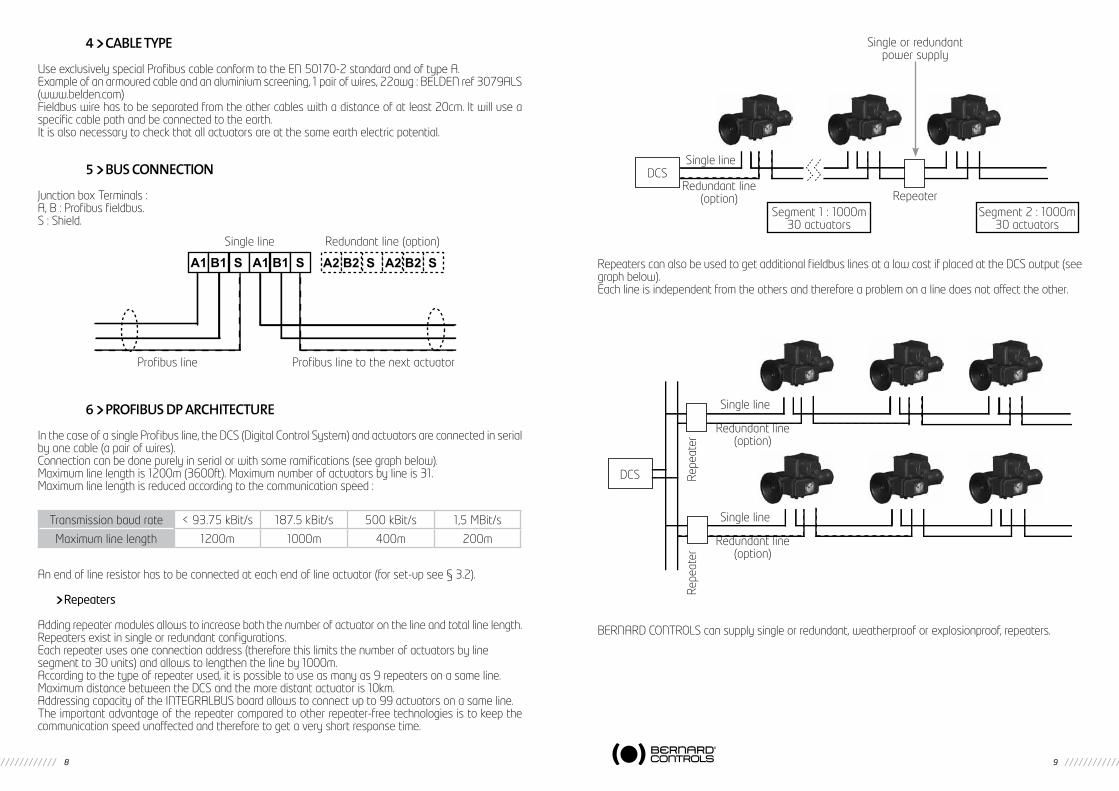
In the case of a single Profibus line, the DCS (Digital Control System) and actuators are connected in serial by one cable (a pair of wires).Connection can be done purely in serial or with some ramifications (see graph below).Maximum line length is 1200m (3600ft). Maximum number of actuators by line is 31.Maximum line length is reduced according to the communication speed :
An end of line resistor has to be connected at each end of line actuator (for set-up see § 3.2).
Repeaters
Adding repeater modules allows to increase both the number of actuator on the line and total line length.Repeaters exist in single or redundant configurations.Each repeater uses one connection address (therefore this limits the number of actuators by linesegment to 30 units) and allows to lengthen the line by 1000m.According to the type of repeater used, it is possible to use as many as 9 repeaters on a same line.Maximum distance between the DCS and the more distant actuator is 10km.Addressing capacity of the INTEGRALBUS board allows to connect up to 99 actuators on a same line.The important advantage of the repeater compared to other repeater-free technologies is to keep the communication speed unaffected and therefore to get a very short response time.
Repeaters can also be used to get additional fieldbus lines at a low cost if placed at the DCS output (see graph below).Each line is independent from the others and therefore a problem on a line does not affect the other.
BERNARD CONTROLS can supply single or redundant, weatherproof or explosionproof, repeaters.
A1 B1 S A1 B1 S A2 B2 S A2 B2 S
Single line Redundant line (option)
Profibus line to the next actuatorProfibus line
Transmission baud rate < 93.75 kBit/s 187.5 kBit/s 500 kBit/s 1,5 MBit/s
Maximum line length 1200m 1000m 400m 200m
Single or redundantpower supply
DCSSingle line
Redundant line(option) Repeater
Segment 1 : 1000m30 actuators
Segment 2 : 1000m30 actuators
DCS
Single line
Single line
Redundant line(option)
Redundant line(option)
Repe
ater
Repe
ater
10 11
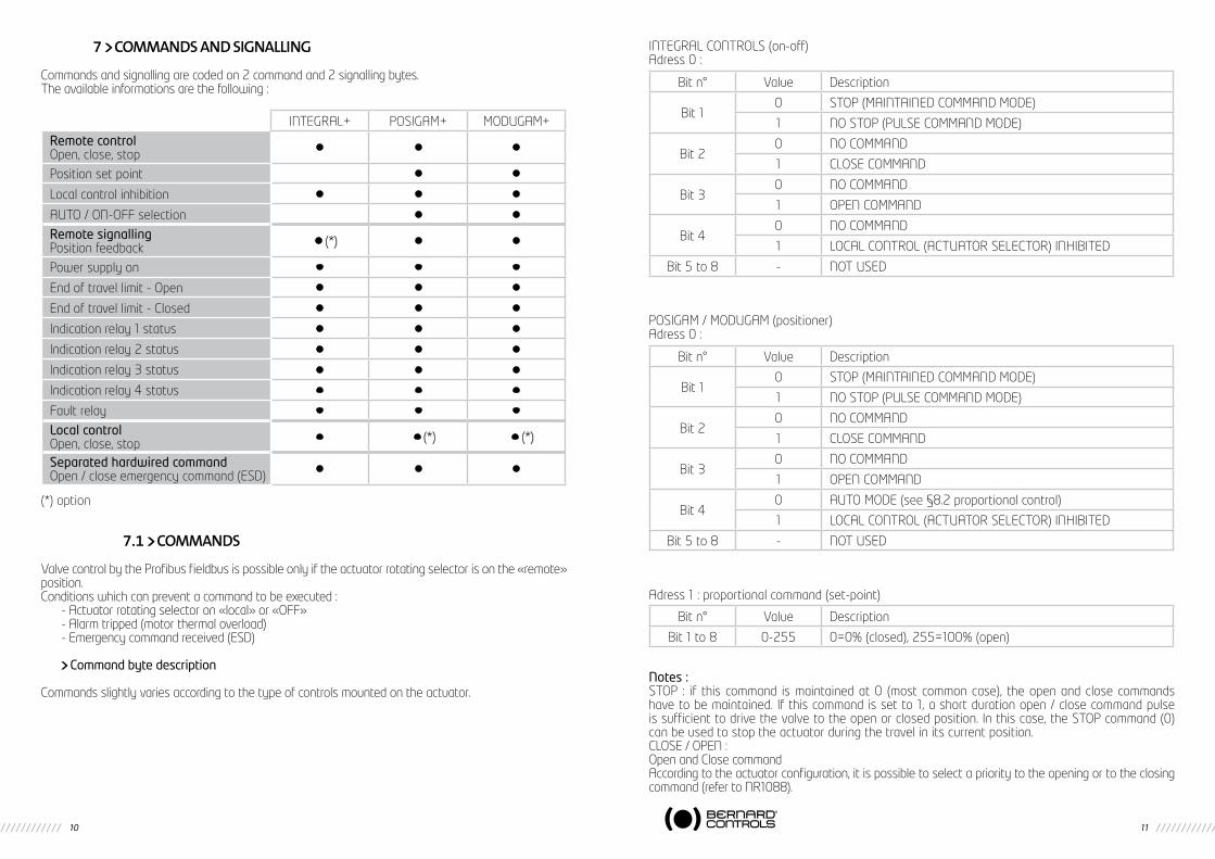
7 COmmANDS AND SIgNALLINg
Commands and signalling are coded on 2 command and 2 signalling bytes.The available informations are the following :
(*) option
7.1 COmmANDS
Valve control by the Profibus fieldbus is possible only if the actuator rotating selector is on the «remote» position.Conditions which can prevent a command to be executed :
- Actuator rotating selector on «local» or «OFF»- Alarm tripped (motor thermal overload)- Emergency command received (ESD)
Command byte description
Commands slightly varies according to the type of controls mounted on the actuator.
INTEGRAL CONTROLS (on-off)Adress 0 :
POSIGAM / MODUGAM (positioner)Adress 0 :
Adress 1 : proportional command (set-point)
Notes :STOP : if this command is maintained at 0 (most common case), the open and close commands have to be maintained. If this command is set to 1, a short duration open / close command pulse is sufficient to drive the valve to the open or closed position. In this case, the STOP command (0) can be used to stop the actuator during the travel in its current position.CLOSE / OPEN :Open and Close commandAccording to the actuator configuration, it is possible to select a priority to the opening or to the closing command (refer to NR1088).
INTEGRAL+ POSIGAM+ MODUGAM+
Remote controlOpen, close, stop • • •
Position set point • •
Local control inhibition • • •
AUTO / ON-OFF selection • •
Remote signallingPosition feedback • (*) • •
Power supply on • • •
End of travel limit - Open • • •
End of travel limit - Closed • • •
Indication relay 1 status • • •
Indication relay 2 status • • •
Indication relay 3 status • • •
Indication relay 4 status • • •
Fault relay • • •
Local controlOpen, close, stop • • (*) • (*)
Separated hardwired commandOpen / close emergency command (ESD) • • •
Bit n° Value Description
Bit 10 STOP (MAINTAINED COMMAND MODE)
1 NO STOP (PULSE COMMAND MODE)
Bit 20 NO COMMAND
1 CLOSE COMMAND
Bit 30 NO COMMAND
1 OPEN COMMAND
Bit 40 NO COMMAND
1 LOCAL CONTROL (ACTUATOR SELECTOR) INHIBITED
Bit 5 to 8 - NOT USED
Bit n° Value Description
Bit 10 STOP (MAINTAINED COMMAND MODE)
1 NO STOP (PULSE COMMAND MODE)
Bit 20 NO COMMAND
1 CLOSE COMMAND
Bit 30 NO COMMAND
1 OPEN COMMAND
Bit 40 AUTO MODE (see §8.2 proportional control)
1 LOCAL CONTROL (ACTUATOR SELECTOR) INHIBITED
Bit 5 to 8 - NOT USED
Bit n° Value Description
Bit 1 to 8 0-255 0=0% (closed), 255=100% (open)
12 13
By default, there is no priority given to either opening or closing.
Priority can be used to :- Allow to reverse the actuator rotation direction during a manoeuvre without having to use the stop
command. In this case, it is necessary to set a priority to the opening or to the closing direction.- Give priority to one or the other rotation direction : if the actuator receives the open and close
commands simultaneously and if the priority has been given to the opening, the actuator will run the open position.
LOCAL CONTROL INHIBITED : allows to prevent any local command even if the actuatorlocal/remote selector button is on «local» position.
AUTO / ON-OFF MODE (positioner versions only) : allows to choose if the actuator has to workin on-off mode (open or close) or in automatic mode (0-100% proportional positioning).
EMERGENCY COMMAND (ESD, Emergency Shut Down) : this command is hardwired (separatewiring) and directly connected to the control box main terminal strip.The ESD is a remote emergency command and has priority over any other command.The ESD can be set to be an opening or a closing command (refer to NR1088).To increase further the availability of the actuator in extreme situations, the ESD can also be setto by-pass the motor thermal protection (refer to NR1088).The ESD command inhibits any command received by the fieldbus. The ESD remains thereforeactive even if the fieldbus communication is lost for any reason.
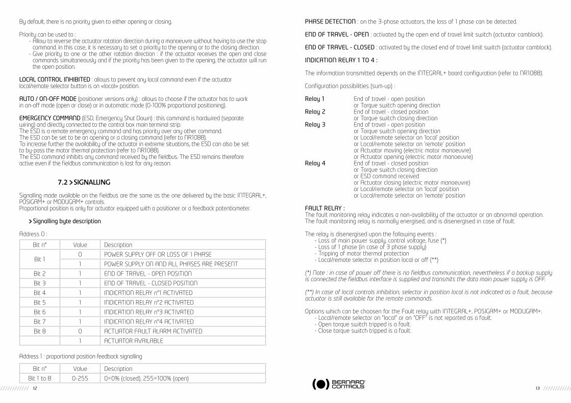
7.2 SIgNALLINg
Signalling made available on the fieldbus are the same as the one delivered by the basic INTEGRAL+, POSIGAM+ or MODUGAM+ controls.Proportional position is only for actuator equipped with a positioner or a feedback potentiometer.
Signalling byte description
Address 0 :
Address 1 : proportional position feedback signalling
PHASE DETECTION : on the 3-phase actuators, the loss of 1 phase can be detected.
END OF TRAVEL - OPEN : activated by the open end of travel limit switch (actuator camblock).
END OF TRAVEL - CLOSED : activated by the closed end of travel limit switch (actuator camblock).
INDICATION RELAY 1 TO 4 :
The information transmitted depends on the INTEGRAL+ board configuration (refer to NR1088).
Configuration possibilities (sum-up) :
Relay 1 End of travel - open position or Torque switch opening directionRelay 2 End of travel - closed position or Torque switch closing directionRelay 3 End of travel - open position or Torque switch opening direction or Local/remote selector on ‘local’ position or Local/remote selector on ‘remote’ position or Actuator moving (electric motor manoeuvre) or Actuator opening (electric motor manoeuvre)Relay 4 End of travel - closed position or Torque switch closing direction or ESD command received or Actuator closing (electric motor manoeuvre) or Local/remote selector on ‘local’ position or Local/remote selector on ‘remote’ position
FAULT RELAY :The fault monitoring relay indicates a non-availability of the actuator or an abnormal operation.The fault monitoring relay is normally energised, and is disenergised in case of fault.
The relay is disenergised upon the following events :- Loss of main power supply, control voltage, fuse (*)- Loss of 1 phase (in case of 3 phase supply)- Tripping of motor thermal protection- Local/remote selector in position local or off (**)
(*) Note : in case of power off there is no fieldbus communication, nevertheless if a backup supply is connected the fieldbus interface is supplied and transmits the data main power supply is OFF.
(**) In case of local controls inhibition, selector in position local is not indicated as a fault, because actuator is still available for the remote commands.
Options which can be choosen for the Fault relay with INTEGRAL+, POSIGAM+ or MODUGAM+.- Local/remote selector on “local” or on “OFF” is not reported as a fault.- Open torque switch tripped is a fault.- Close torque switch tripped is a fault.
Bit n° Value Description
Bit 10 POWER SUPPLY OFF OR LOSS OF 1 PHASE
1 POWER SUPPLY ON AND ALL PHASES ARE PRESENT
Bit 2 1 END OF TRAVEL - OPEN POSITION
Bit 3 1 END OF TRAVEL - CLOSED POSITION
Bit 4 1 INDICATION RELAY n°1 ACTIVATED
Bit 5 1 INDICATION RELAY n°2 ACTIVATED
Bit 6 1 INDICATION RELAY n°3 ACTIVATED
Bit 7 1 INDICATION RELAY n°4 ACTIVATED
Bit 8 0 ACTUATOR FAULT ALARM ACTIVATED
1 ACTUATOR AVAILABLE
Bit n° Value Description
Bit 1 to 8 0-255 0=0% (closed), 255=100% (open)
14 15
1 INTRODUCTION
Profibus DP est un bus de terrain qui permet de connecter des servomoteurs à un système de commande DCS (Digital Control system). Plusieurs servomoteurs ou autres appareils équipés d’une interface correspondante au bus de terrain peuvent être connectés sur une même ligne de bus. L’interface Profibus DP décrite dans cette notice est destinée aux servomoteurs BER-NAD CONTROLS version INTEGRAL+, POSIGAM+ ou MODUGAM+. Pour des servomoteurs version INTELLI+ se reporter à la notice Profibus DPV1 pour INTELLI+. Des coffrets avec l’interface Profibus DP peuvent être fournis pour raccorder des appareils non équipés.
Bus de terrain simple ou redondant
Pour obtenir une continuité de communication même en cas de coupure de ligne il est possible de choisir un bus redondant. Le DCS doit gérer 2 lignes de bus. L’interface servomoteur comprend dans ce cas une carte fille avec une entrée supplémentaire isolée Profibus DP. En cas de défaillance sur la ligne principale le DCS peut encore communiquer par la ligne auxiliaire.Selon le type de bus voulu une interface INTEGRALBUS simple ou redondante peut équiper le servomoteur.
2 CARACTERISTIQUES TECHNIQUES
- La carte PROFIBUS-DP esclave peut être commandée à partir d’une carte PROFIBUS-DP maître : PLC, PC, DCS cartes d’interfaces…de fournisseurs divers.
- Type de support physique RS 485.- Vitesse autoadaptative : 9,6K-1.5M bauds.- Adressage des servomoteurs de 1 à 99- Nombre maximal de servomoteurs connectés sur une ligne: 31 (jusqu’à 99 avec répéteurs)- 2 leds d’états du bus et 1 led pour la présence de l’alimentation.- Approuvé par PNO (Profibus Nutzer Organisation).- Conformité CE.- Nom du fichier GSD : version simple N° LBVS0990.GSD version redondante N° LBVR0990.GSD- Le bus de terrain est complètement isolé électriquement des circuits du servomoteur. En cas
de version redondante, chaque canal de communication est isolé électriquement des circuits du servomoteur et isolé l’un de l’autre.
- Une coupure de l’alimentation du servomoteur n’interrompt pas la ligne du bus.- Les températures de fonctionnement sont celles du servomoteur équipé.
3 INTERFACE PROFIBUS DP
3.1 DESCRIPTION PHYSIQUELire les instructions de mise en service de l’INTEGRAL+ (réf. NR1088) avant de commencer
les réglages de l’interface INTEGRALBUS.
Fusible TR5 315mA250V
Connecteur J3
Cavalier CAV 1
Carte INTEGRALBUS PROFIBUS-DP
Cavaliers J1 et J2
16 17
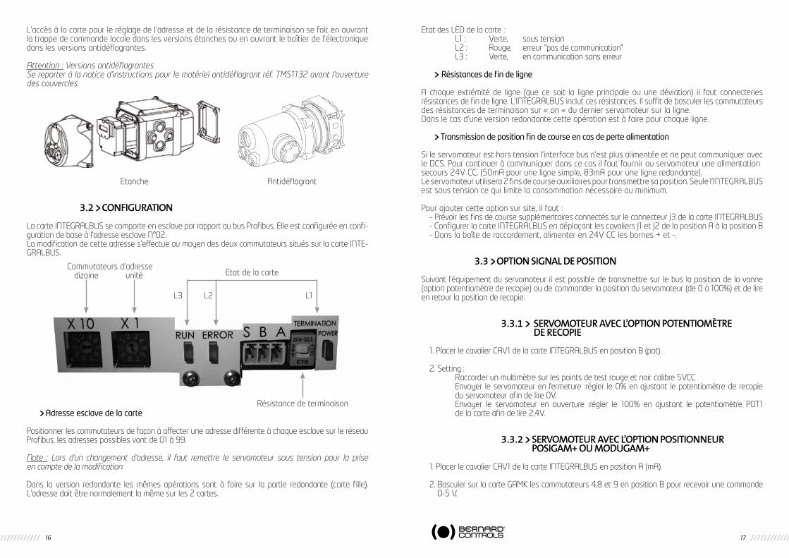
L’accès à la carte pour le réglage de l’adresse et de la résistance de terminaison se fait en ouvrant la trappe de commande locale dans les versions étanches ou en ouvrant le boîtier de l’électronique dans les versions antidéflagrantes.
Attention : Versions antidéflagrantesSe reporter à la notice d’instructions pour le matériel antidéflagrant réf. TMS1132 avant l’ouverture des couvercles.
Etanche Antidéflagrant
3.2 CONFIgURATION
La carte INTEGRALBUS se comporte en esclave par rapport au bus Profibus. Elle est configurée en confi-guration de base à l’adresse esclave N°02.La modification de cette adresse s’effectue au moyen des deux commutateurs situés sur la carte INTE-GRALBUS.
Adresse esclave de la carte
Positionner les commutateurs de façon à affecter une adresse différente à chaque esclave sur le réseau Profibus, les adresses possibles vont de 01 à 99.
Note : Lors d’un changement d’adresse, il faut remettre le servomoteur sous tension pour la prise en compte de la modification.
Dans la version redondante les mêmes opérations sont à faire sur la partie redondante (carte fille). L’adresse doit être normalement la même sur les 2 cartes.
Etat des LED de la carte : L1 : Verte, sous tension L2 : Rouge, erreur “pas de communication” L3 : Verte, en communication sans erreur
Résistances de fin de ligne
A chaque extrémité de ligne (que ce soit la ligne principale ou une déviation) il faut connecterles résistances de fin de ligne. L’INTEGRALBUS inclut ces résistances. Il suffit de basculer les commutateursdes résistances de terminaison sur « on « du dernier servomoteur sur la ligne.Dans le cas d’une version redondante cette opération est à faire pour chaque ligne.
Transmission de position fin de course en cas de perte alimentation
Si le servomoteur est hors tension l’interface bus n’est plus alimentée et ne peut communiquer avec le DCS. Pour continuer à communiquer dans ce cas il faut fournir au servomoteur une alimentationsecours 24V CC, (50mA pour une ligne simple, 83mA pour une ligne redondante).Le servomoteur utilisera 2 fins de course auxiliaires pour transmettre sa position. Seule l’INTEGRALBUS est sous tension ce qui limite la consommation nécessaire au minimum.
Pour ajouter cette option sur site, il faut :- Prévoir les fins de course supplémentaires connectés sur le connecteur J3 de la carte INTEGRALBUS- Configurer la carte INTEGRALBUS en déplaçant les cavaliers J1 et J2 de la position A à la position B- Dans la boîte de raccordement, alimenter en 24V CC les bornes + et -.
3.3 OPTION SIgNAL DE POSITION
Suivant l’équipement du servomoteur il est possible de transmettre sur le bus la position de la vanne (option potentiomètre de recopie) ou de commander la position du servomoteur (de 0 à 100%) et de lire en retour la position de recopie.
3.3.1 SERvOmOTEUR AvEC L’OPTION POTENTIOmèTRE DE RECOPIE
1. Placer le cavalier CAV1 de la carte INTEGRALBUS en position B (pot).
2. Setting : Raccorder un multimètre sur les points de test rouge et noir calibre 5VCC Envoyer le servomoteur en fermeture :régler le 0% en ajustant le potentiomètre de recopie
du servomoteur afin de lire 0V. Envoyer le servomoteur en ouverture :régler le 100% en ajustant le potentiomètre POT1
de la carte afin de lire 2,4V.
3.3.2 SERvOmOTEUR AvEC L’OPTION POSITIONNEUR POSIgAm+ OU mODUgAm+
1. Placer le cavalier CAV1 de la carte INTEGRALBUS en position A (mA).
2. Basculer sur la carte GAMK les commutateurs 4,8 et 9 en position B pour recevoir une commande 0-5 V.
Commutateurs d’adresse dizaine unité
Résistance de terminaison
Etat de la carte
L1L2L3
18 19
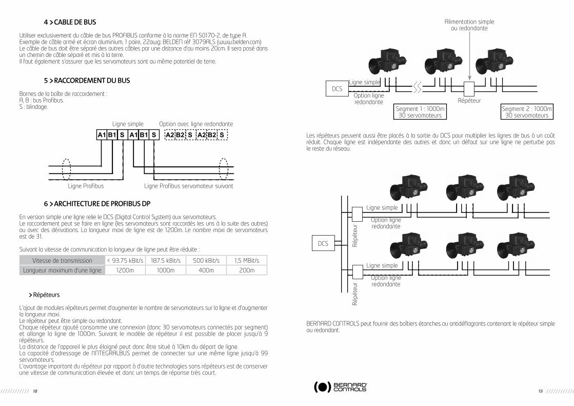
4 CABLE DE BUS
Utiliser exclusivement du câble de bus PROFIBUS conforme à la norme EN 50170-2, de type A.Exemple de câble armé et écran aluminium, 1 paire, 22awg: BELDEN réf 3079ALS (www.belden.com)Le câble de bus doit être séparé des autres câbles par une distance d’au moins 20cm. Il sera posé dans un chemin de câble séparé et mis à la terre.Il faut également s’assurer que les servomoteurs sont au même potentiel de terre.
5 RACCORDEmENT DU BUS
Bornes de la boîte de raccordement :A, B : bus Profibus.S : blindage.
6 ARCHITECTURE DE PROFIBUS DP
En version simple une ligne relie le DCS (Digital Control System) aux servomoteurs.Le raccordement peut se faire en ligne (les servomoteurs sont raccordés les uns à la suite des autres) ou avec des dérivations. La longueur maxi de ligne est de 1200m. Le nombre maxi de servomoteurs est de 31.
Suivant la vitesse de communication la longueur de ligne peut être réduite :
Répéteurs
L’ajout de modules répéteurs permet d’augmenter le nombre de servomoteurs sur la ligne et d’augmenter la longueur maxi.Le répéteur peut être simple ou redondant.Chaque répéteur ajouté consomme une connexion (donc 30 servomoteurs connectés par segment)et allonge la ligne de 1000m. Suivant le modèle de répéteur il est possible de placer jusqu’à 9 répéteurs.La distance de l’appareil le plus éloigné peut donc être situé à 10km du départ de ligne.La capacité d’adressage de l’INTEGRALBUS permet de connecter sur une même ligne jusqu’à 99 servomoteurs.L’avantage important du répéteur par rapport à d’autre technologies sans répéteurs est de conserver une vitesse de communication élevée et donc un temps de réponse très court.
Les répéteurs peuvent aussi être placés à la sortie du DCS pour multiplier les lignes de bus à un coût réduit. Chaque ligne est indépendante des autres et donc un défaut sur une ligne ne perturbe pas le reste du réseau.
BERNARD CONTROLS peut fournir des boîtiers étanches ou antidéflagrants contenant le répéteur simple ou redondant.
A1 B1 S A1 B1 S A2 B2 S A2 B2 S
Ligne simple Option avec ligne redondante
Ligne Profibus servomoteur suivantLigne Profibus
Vitesse de transmission < 93.75 kBit/s 187.5 kBit/s 500 kBit/s 1,5 MBit/s
Longueur maximum d’une ligne 1200m 1000m 400m 200m
Alimentation simpleou redondante
DCSLigne simple
Option ligneredondante Répéteur
Segment 1 : 1000m30 servomoteurs
Segment 2 : 1000m30 servomoteurs
DCS
Ligne simple
Ligne simple
Option ligneredondante
Option ligneredondante
Répé
teur
Répé
teur
20 21
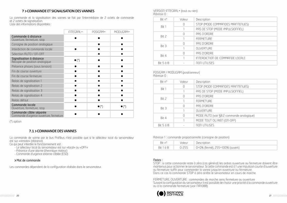
7 COmmANDE ET SIgNALISATION DES vANNES
La commande et la signalisation des vannes se fait par l’intermédiaire de 2 octets de commande et 2 octets de signalisation.Liste des informations disponibles :
(*) option
7.1 COmmANDE DES vANNES
La commande de vanne par le bus Profibus n’est possible que si le sélecteur local du servomoteur est sur «remote» (distance).Ce qui peut interdire le fonctionnement est :
- Le sélecteur local du servomoteur est sur «local» ou «OFF»- Présence d’une alarme (thermique moteur)- Commande d’urgence externe câblée (ESD)
Mot de commande
Les commandes dépendent de la configuration réalisée dans le servomoteur.
VERSION INTEGRAL+ (tout ou rien)Adresse 0 :
POSIGAM / MODUGAM (positionneur)Adresse 0 :
Adresse 1 : commande proportionnelle (consigne de position)
Notes :STOP : si cette commande reste à zéro (cas général) les ordres ouverture ou fermeture doivent être maintenus pour actionner le servomoteur. Si cette commande est à 1 une impulsion courte d’ouverture ou fermeture suffit pour commander la vanne jusqu’en ouverture ou fermeture.Dans ce cas la commande STOP à zéro arrête le servomoteur en cours de marche.
FERMETURE, OUVERTURE : commandes de marche sens fermeture ou ouvertureSuivant la configuration du servomoteur il est possible de choisir une priorité à la commande ouverture ou à la commande fermeture (voir NR1088).
INTEGRAL+ POSIGAM+ MODUGAM+
Commande à distanceOuverture, fermeture, stop • • •
Consigne de position analogique • •
Interdiction de commande locale • • •
Sélection AUTO / ON-OFF • •
Signalisation à distanceRecopie de position analogique • (*) • •
Présence phases (sous tension) • • •
Fin de course ouverture • • •
Fin de course fermeture • • •
Relais de signalisation 1 • • •
Relais de signalisation 2 • • •
Relais de signalisation 3 • • •
Relais de signalisation 4 • • •
Relais défaut • • •
Commande localeOuverture, fermeture, stop • • (*) • (*)
Commande câble séparéeCommande d’urgence ouverture, fermeture • • •
Bit n° Valeur Description
Bit 10 STOP (MODE COMMANDES MAINTENUES)
1 PAS DE STOP (MODE IMPULSIONNEL)
Bit 20 PAS D’ORDRE
1 FERMETURE
Bit 30 PAS D’ORDRE
1 OUVERTURE
Bit 40 PAS D’ORDRE
1 INTERDICTION DE COMMANDE LOCALE
Bit 5 à 8 - NON UTILISES
Bit n° Valeur Description
Bit 10 STOP (MODE COMMANDES MAINTENUES)
1 PAS DE STOP (MODE IMPULSIONNEL)
Bit 20 PAS D’ORDRE
1 FERMETURE
Bit 30 PAS D’ORDRE
1 OUVERTURE
Bit 40 MODE AUTO (voir §8.2 commande analogique)
1 MODE TOUT OU RIEN (ON-OFF)
Bit 5 à 8 - NON UTILISES
Bit n° Valeur Description
Bit 1 à 8 0-255 0=0% (fermé), 255=100% (ouvert)
22 23
En standard, il n’y a pas de priorité à l’ouverture ou à la fermeture. Les priorités servent :- A inverser le sens de marche en cours de manoeuvre sans passer par une commande stop. Il faut
dans ce cas configurer une priorité à l’ouverture et à la fermeture.- Donner la priorité à un sens de rotation : si le servomoteur reçoit 2 ordres ouverture et fermeture
simultanés et qu’une priorité ouverture a été choisie, alors le servomoteur va en ouverture.
INTERDICTION DE COMMANDE LOCALE : permet à distance d’interdire la commande locale même si le sélecteur du servomoteur est sur la position «local».
AUTO/ON-OFF (versions avec positionneur seulement) : cette commande n’est pas Interdiction de commande locale mais permet de sélectionner soit la commande tout ou rien (ouverture fermeture) soit la commande proportionnelle par le positionneur (0-100%).
COMMANDE D’URGENCE (ESD, Emergency Shut Down) : cette commande est amenée par un câble séparé du bus et raccordé sur le bornier servomoteur.L’ESD est une commande d’urgence à distance, prioritaire sur toute autre commande. Suivant l’utilisation de la vanne, l’ordre d’urgence sera une ouverture ou une fermeture. Pour augmenter la disponibilité du servomoteur dans les situations extrêmes, la commande d’urgence peut aussi shunter la protection ther-mique du moteur (voir NR1088).La commande ESD shunte l’interface bus et donc est active même si le bus est hors service.
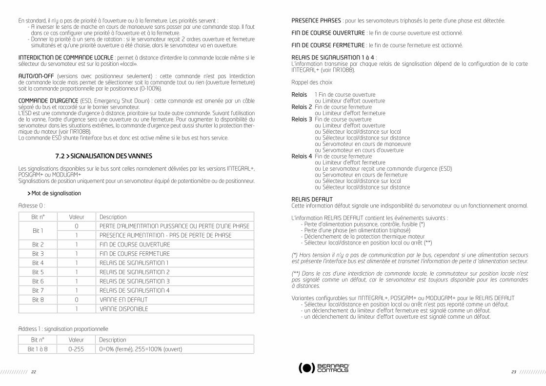
7.2 SIgNALISATION DES vANNES
Les signalisations disponibles sur le bus sont celles normalement délivrées par les versions INTEGRAL+, POSIGAM+ ou MODUGAM+Signalisations de position uniquement pour un servomoteur équipé de potentiomètre ou de positionneur.
Mot de signalisation
Adresse 0 :
Address 1 : signalisation proportionnelle
PRESENCE PHASES : pour les servomoteurs triphasés la perte d’une phase est détectée.
FIN DE COURSE OUVERTURE : le fin de course ouverture est actionné.
FIN DE COURSE FERMETURE : le fin de course fermeture est actionné.
RELAIS DE SIGNALISATION 1 à 4 :L’information transmise par chaque relais de signalisation dépend de la configuration de la carte INTEGRAL+ (voir NR1088).
Rappel des choix
Relais 1 Fin de course ouverture ou Limiteur d’effort ouvertureRelais 2 Fin de course fermeture ou Limiteur d’effort fermetureRelais 3 Fin de course ouverture ou Limiteur d’effort ouverture ou Sélecteur local/distance sur local ou Sélecteur local/distance sur distance ou Servomoteur en cours de manoeuvre ou Servomoteur en cours d’ouvertureRelais 4 Fin de course fermeture ou Limiteur d’effort fermeture ou Le servomoteur reçoit une commande d’urgence (ESD) ou Servomoteur en cours de fermeture ou Sélecteur local/distance sur local ou Sélecteur local/distance sur distance
RELAIS DEFAUTCette information défaut signale une indisponibilité du servomoteur ou un fonctionnement anormal.
L’information RELAIS DEFAUT contient les événements suivants :- Perte d’alimentation puissance, contrôle, fusible (*)- Perte d’une phase (en alimentation triphasé)- Déclenchement de la protection thermique moteur- Sélecteur local/distance en position local ou arrêt (**)
(*) Hors tension il n’y a pas de communication par le bus, cependant si une alimentation secours est présente l’interface bus est alimentée et transmet l’information de perte d ‘alimentation secteur.
(**) Dans le cas d’une interdiction de commande locale, le commutateur sur position locale n’est pas signalé comme un défaut, car le servomoteur est toujours disponible pour les commandes à distances.
Variantes configurables sur l’INTEGRAL+, POSIGAM+ ou MODUGAM+ pour le RELAIS DEFAUT- Sélecteur local/distance en position local ou arrêt n’est pas reporté comme un défaut.- un déclenchement du limiteur d’effort fermeture est signalé comme un défaut.- un déclenchement du limiteur d’effort ouverture est signalé comme un défaut.
Bit n° Valeur Description
Bit 10 PERTE D’ALIMENTATION PUISSANCE OU PERTE D’UNE PHASE
1 PRESENCE ALIMENTATION - PAS DE PERTE DE PHASE
Bit 2 1 FIN DE COURSE OUVERTURE
Bit 3 1 FIN DE COURSE FERMETURE
Bit 4 1 RELAIS DE SIGNALISATION 1
Bit 5 1 RELAIS DE SIGNALISATION 2
Bit 6 1 RELAIS DE SIGNALISATION 3
Bit 7 1 RELAIS DE SIGNALISATION 4
Bit 8 0 VANNE EN DEFAUT
1 VANNE DISPONIBLE
Bit n° Valeur Description
Bit 1 à 8 0-255 0=0% (fermé), 255=100% (ouvert)

24 25
1 EINLEITUNg
Profibus DP ist ein Feldbus, der den Anschluss von Stellantrieben an ein DCS-Steuerungssystem (Digital Control System) erlaubt. Mehrere Stellantriebe oder andere mit einer Feldbus-Schnittstelle ausgestattete Geräte können an dieselbe Feldbusleitung angeschlossen werden.Die in dieser Anleitung beschriebene Profibus DP-Schnittstelle ist speziell für die Stellantriebe von L.Bernard mit den Steuerungen INTEGRAL+, POSIGAM+ oder MODUGAM+ konzipiert. Für Stellantriebe mit der Steuerung INTELLI+, siehe Anleitung Profibus DPV1 für INTELLI+.Schaltkästen mit integrierter Profibus DP-Schnittstelle können für den Anschluss von nicht ausgerüsteten Geräten geliefert werden.
Einfacher oder redundanter Feldbus
Der redundante Bus dient dazu, selbst bei Unterbrechung einer Leitung Kommunikationskontinuität zu garantieren. Dabei muss das DCS 2 Busleitungen verwalten. Die Stellantrieb-Schnittstelle enthält in diesem Fall eine Tochterkarte mit einem zusätzlichen isolierten Profibus DP-Eingang. Bei einer Störung der Hauptleitung kann das DCS weiter über die Hilfsleitung kommunizieren.Je nach gewünschtem Bustyp kann der Stellantrieb mit einer einfachen oder redundanten INTEGRALBUS- Schnittstelle ausgestattet werden.
2 TECHNISCHE DATEN
- Die PROFIBUS-DP-Slave-Karte kann von einer PROFIBUS-DP-Master-Karte aus gesteuert werden: PLC-, PC-, DCS-Schnittstellenkarten ... verschiedener Lieferanten.
- Hardware Kommunikationsstandard RS 485.- Automatische Geschwindigkeitswahl: 9,6 kBaud - 1,5 MBaud. Adressierung der Stellantriebe
von 1 bis 99- Höchstzahl der Stellantriebe pro Leitung: 31 (bis zu 99 mit Repeatern)- 2 Bus-Status-LEDs und 1 Stromversorgungs-LED.- Zugelassen von der PNO (Profibus Nutzer Organisation).- CE-Konformität.- GSD-Dateiname: einfache Ausführung Nr. LBVS0990.GSD redundante Ausführung Nr. LBVR0990.GSD- Der Feldbus ist von den Stromkreisen des Stellantriebs elektrisch völlig isoliert. Bei der redundanten
Ausführung sind die beiden Kommunikationskanäle elektrisch von den Stromkreisen des Stellantriebs und untereinander isoliert.
- Eine Stromunterbrechung des Stellantriebs unterbricht nicht die Busleitung.- Die Betriebstemperaturen entsprechen jenen des ausgerüsteten Stellantriebs.
3 PROFIBUS DP-SCHNITTSTELLE
3.1 HARDwAREBESCHREIBUNgSiehe Bedienungshandbuch INTEGRAL+ (Ref. NR1088) vor Beginn der Einstellungen
der INTEGRALBUS-Schnittstelle.
SicherungTR5 315mA 250V
Steckverbinder J3
Jumper CAV 1
INTEGRALBUS PROFIBUS-DP-Karte
Jumper J1 und J2
26 27
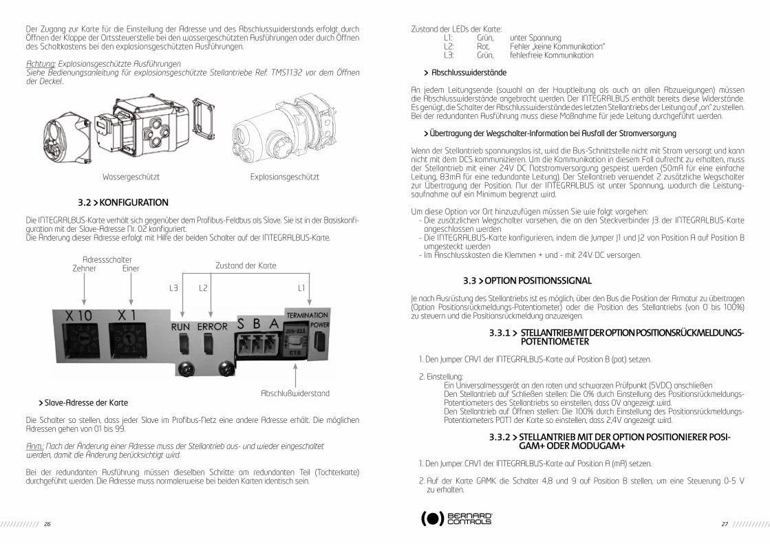
Der Zugang zur Karte für die Einstellung der Adresse und des Abschlusswiderstands erfolgt durch Öffnen der Klappe der Ortssteuerstelle bei den wassergeschützten Ausführungen oder durch Öffnen des Schaltkastens bei den explosionsgeschützten Ausführungen.
Achtung: Explosionsgeschützte AusführungenSiehe Bedienungsanleitung für explosionsgeschützte Stellantriebe Ref. TMS1132 vor dem Öffnen der Deckel..
Wassergeschützt Explosionsgeschützt
3.2 kONFIgURATION
Die INTEGRALBUS-Karte verhält sich gegenüber dem Profibus-Feldbus als Slave. Sie ist in der Basiskonfi-guration mit der Slave-Adresse Nr. 02 konfiguriert.Die Änderung dieser Adresse erfolgt mit Hilfe der beiden Schalter auf der INTEGRALBUS-Karte.
Slave-Adresse der Karte
Die Schalter so stellen, dass jeder Slave im Profibus-Netz eine andere Adresse erhält. Die möglichen Adressen gehen von 01 bis 99.
Anm.: Nach der Änderung einer Adresse muss der Stellantrieb aus- und wieder eingeschaltetwerden, damit die Änderung berücksichtigt wird.
Bei der redundanten Ausführung müssen dieselben Schritte am redundanten Teil (Tochterkarte) durchgeführt werden. Die Adresse muss normalerweise bei beiden Karten identisch sein.
Zustand der LEDs der Karte: L1: Grün, unter Spannung L2: Rot, Fehler „keine Kommunikation“ L3: Grün, fehlerfreie Kommunikation
Abschlusswiderstände
An jedem Leitungsende (sowohl an der Hauptleitung als auch an allen Abzweigungen) müssen die Abschlusswiderstände angebracht werden. Der INTEGRALBUS enthält bereits diese Widerstände. Es genügt, die Schalter der Abschlusswiderstände des letzten Stellantriebs der Leitung auf „on“ zu stellen. Bei der redundanten Ausführung muss diese Maßnahme für jede Leitung durchgeführt werden.
Übertragung der Wegschalter-Information bei Ausfall der Stromversorgung
Wenn der Stellantrieb spannungslos ist, wird die Bus-Schnittstelle nicht mit Strom versorgt und kann nicht mit dem DCS kommunizieren. Um die Kommunikation in diesem Fall aufrecht zu erhalten, muss der Stellantrieb mit einer 24V DC Notstromversorgung gespeist werden (50mA für eine einfache Leitung, 83mA für eine redundante Leitung). Der Stellantrieb verwendet 2 zusätzliche Wegschalter zur Übertragung der Position. Nur der INTEGRALBUS ist unter Spannung, wodurch die Leistung-saufnahme auf ein Minimum begrenzt wird.
Um diese Option vor Ort hinzuzufügen müssen Sie wie folgt vorgehen:- Die zusätzlichen Wegschalter vorsehen, die an den Steckverbinder J3 der INTEGRALBUS-Karte
angeschlossen werden- Die INTEGRALBUS-Karte konfigurieren, indem die Jumper J1 und J2 von Position A auf Position B
umgesteckt werden- Im Anschlusskasten die Klemmen + und - mit 24V DC versorgen.
3.3 OPTION POSITIONSSIgNAL
Je nach Ausrüstung des Stellantriebs ist es möglich, über den Bus die Position der Armatur zu übertragen (Option Positionsrückmeldungs-Potentiometer) oder die Position des Stellantriebs (von 0 bis 100%) zu steuern und die Positionsrückmeldung anzuzeigen.
3.3.1 STELLANTRIEB mIT DER OPTION POSITIONSRüCkmELDUNgS-POTENTIOmETER
1. Den Jumper CAV1 der INTEGRALBUS-Karte auf Position B (pot) setzen.
2. Einstellung: Ein Universalmessgerät an den roten und schwarzen Prüfpunkt (5VDC) anschließen Den Stellantrieb auf Schließen stellen: Die 0% durch Einstellung des Positionsrückmeldungs-
Potentiometers des Stellantriebs so einstellen, dass 0V angezeigt wird. Den Stellantrieb auf Öffnen stellen: Die 100% durch Einstellung des Positionsrückmeldungs-
Potentiometers POT1 der Karte so einstellen, dass 2,4V angezeigt wird.
3.3.2 STELLANTRIEB mIT DER OPTION POSITIONIERER POSI-gAm+ ODER mODUgAm+
1. Den Jumper CAV1 der INTEGRALBUS-Karte auf Position A (mA) setzen.
2. Auf der Karte GAMK die Schalter 4,8 und 9 auf Position B stellen, um eine Steuerung 0-5 V zu erhalten.
Adressschalter Zehner Einer
Abschlußwiderstand
Zustand der Karte
L1L2L3
28 29
4 FELDBUSkABEL
Ausschließlich ein PROFIBUS-Buskabel benutzen, das der Norm EN 50170-2, Typ A, entspricht.Beispiel eines bewehrten Kabels und einer Aluminium-Abschirmung, 1 Doppelleitung, 22awg: BELDEN Ref. 3079ALS (www.belden.com)Das Kabel muss von den anderen Kabeln durch einen Abstand von mindestens 20 cm getrennt sein. Es wird auf einem getrennten Kabelweg verlegt und geerdet.Außerdem muss sichergestellt werden, dass die Stellantriebe dasselbe Erdpotential haben.
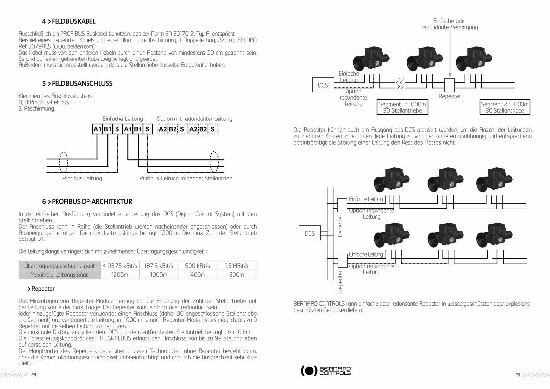
5 FELDBUSANSCHLUSS
Klemmen des Anschlusskastens:A, B: Profibus-Feldbus.S: Abschirmung.
6 PROFIBUS DP-ARCHITEkTUR
In der einfachen Ausführung verbindet eine Leitung das DCS (Digital Control System) mit den Stellantrieben.Der Anschluss kann in Reihe (die Stellantrieb werden nacheinander angeschlossen) oder durch Abzweigungen erfolgen. Die max. Leitungslänge beträgt 1200 m. Die max. Zahl der Stellantrieb beträgt 31.
Die Leitungslänge verringert sich mit zunehmender Übertragungsgeschwindigkeit :
Repeater
Das Hinzufügen von Repeater-Modulen ermöglicht die Erhöhung der Zahl der Stellantriebe auf der Leitung sowie der max. Länge. Der Repeater kann einfach oder redundant sein.Jeder hinzugefügte Repeater verwendet einen Anschluss (daher 30 angeschlossene Stellantriebe pro Segment) und verlängert die Leitung um 1000 m. Je nach Repeater-Modell ist es möglich, bis zu 9 Repeater auf derselben Leitung zu benutzen.Die maximale Distanz zwischen dem DCS und dem entferntesten Stellantrieb beträgt also 10 km.Die Adressierungskapazität des INTEGRALBUS erlaubt den Anschluss von bis zu 99 Stellantrieben auf derselben Leitung.Der Hauptvorteil des Repeaters gegenüber anderen Technologien ohne Repeater besteht darin, dass die Kommunikationsgeschwindigkeit unbeeinträchtigt und dadurch die Ansprechzeit sehr kurz bleibt.
Die Repeater können auch am Ausgang des DCS platziert werden, um die Anzahl der Leitungen zu niedrigen Kosten zu erhöhen. Jede Leitung ist von den anderen unabhängig und entsprechend beeinträchtigt die Störung einer Leitung den Rest des Netzes nicht.
BERNARD CONTROLS kann einfache oder redundante Repeater in wassergeschützten oder explosions-geschützten Gehäusen liefern.
A1 B1 S A1 B1 S A2 B2 S A2 B2 S
Einfache Leitung Option mit redundanter Leitung
Profibus-Leitung folgender StellantriebProfibus-Leitung
Übertragungsgeschwindigkeit < 93.75 kBit/s 187.5 kBit/s 500 kBit/s 1,5 MBit/s
Maximale Leitungslänge 1200m 1000m 400m 200m
Einfache oderredundante Versorgung
DCS
EinfacheLeitung
Optionredundante
LeitungRepeater
Segment 1 : 1000m30 Stellantriebe
Segment 2 : 1000m30 Stellantriebe
DCS
Einfache Leitung
Einfache Leitung
Option redundanteLeitung
Option redundanteLeitung
Repe
ater
Repe
ater
30 31
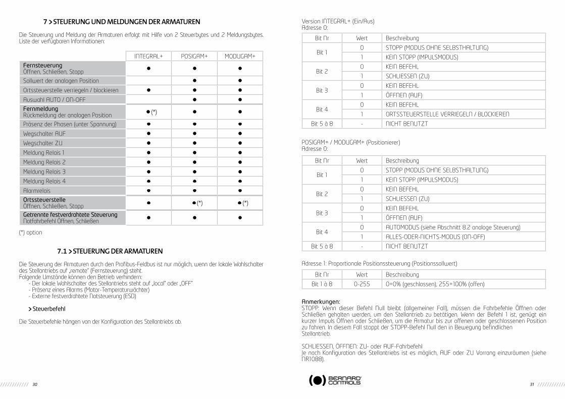
7 STEUERUNg UND mELDUNgEN DER ARmATUREN
Die Steuerung und Meldung der Armaturen erfolgt mit Hilfe von 2 Steuerbytes und 2 Meldungsbytes. Liste der verfügbaren Informationen:
(*) option
7.1 STEUERUNg DER ARmATUREN
Die Steuerung der Armaturen durch den Profibus-Feldbus ist nur möglich, wenn der lokale Wahlschalter des Stellantriebs auf „remote“ (Fernsteuerung) steht.Folgende Umstände können den Betrieb verhindern:
- Der lokale Wahlschalter des Stellantriebs steht auf „local“ oder „OFF”- Präsenz eines Alarms (Motor-Temperaturwächter)- Externe festverdrahtete Notsteuerung (ESD)
Steuerbefehl
Die Steuerbefehle hängen von der Konfiguration des Stellantriebs ab.
Version INTEGRAL+ (Ein/Aus)Adresse 0:
POSIGAM+ / MODUGAM+ (Positionierer)Adresse 0:
Adresse 1: Proportionale Positionssteuerung (Positionssollwert)
Anmerkungen:STOPP: Wenn dieser Befehl Null bleibt (allgemeiner Fall), müssen die Fahrbefehle Öffnen oder Schließen gehalten werden, um den Stellantrieb zu betätigen. Wenn der Befehl 1 ist, genügt ein kurzer Impuls Öffnen oder Schließen, um die Armatur bis zur offenen oder geschlossenen Position zu fahren. In diesem Fall stoppt der STOPP-Befehl Null den in Bewegung befindlichenStellantrieb.
SCHLIESSEN, ÖFFNEN: ZU- oder AUF-FahrbefehlJe nach Konfiguration des Stellantriebs ist es möglich, AUF oder ZU Vorrang einzuräumen (siehe NR1088).
INTEGRAL+ POSIGAM+ MODUGAM+
FernsteuerungÖffnen, Schließen, Stopp • • •
Sollwert der analogen Position • •
Ortssteuerstelle verriegeln / blockieren • • •
Auswahl AUTO / ON-OFF • •
FernmeldungRückmeldung der analogen Position • (*) • •
Präsenz der Phasen (unter Spannung) • • •
Wegschalter AUF • • •
Wegschalter ZU • • •
Meldung Relais 1 • • •
Meldung Relais 2 • • •
Meldung Relais 3 • • •
Meldung Relais 4 • • •
Alarmrelais • • •
OrtssteuerstelleÖffnen, Schließen, Stopp • • (*) • (*)
Getrennte festverdrahtete SteuerungNotfahrbefehl Öffnen, Schließen • • •
Bit Nr Wert Beschreibung
Bit 10 STOPP (MODUS OHNE SELBSTHALTUNG)
1 KEIN STOPP (IMPULSMODUS)
Bit 20 KEIN BEFEHL
1 SCHLIESSEN (ZU)
Bit 30 KEIN BEFEHL
1 ÖFFNEN (AUF)
Bit 40 KEIN BEFEHL
1 ORTSSTEUERSTELLE VERRIEGELN / BLOCKIEREN
Bit 5 à 8 - NICHT BENUTZT
Bit Nr Wert Beschreibung
Bit 10 STOPP (MODUS OHNE SELBSTHALTUNG)
1 KEIN STOPP (IMPULSMODUS)
Bit 20 KEIN BEFEHL
1 SCHLIESSEN (ZU)
Bit 30 KEIN BEFEHL
1 ÖFFNEN (AUF)
Bit 40 AUTOMODUS (siehe Abschnitt 8.2 analoge Steuerung)
1 ALLES-ODER-NICHTS-MODUS (ON-OFF)
Bit 5 à 8 - NICHT BENUTZT
Bit Nr Wert Beschreibung
Bit 1 à 8 0-255 0=0% (geschlossen), 255=100% (offen)
32 33
In der Standard-Einstellung besteht kein Vorrang für AUF oder ZU. Der Vorrang kann in folgenden Fällen sinnvoll sein:
- Beim Drehrichtungswechsel während des AUF oder ZU-Fahrens, ohne die Stopp-Funktion zu nutzen. In diesem Fall muss ein Vorrang für AUF und ZU konfiguriert werden.
- Beim Vorrang für eine Richtung: Wenn der Stellantrieb gleichzeitig einen AUF und ZUFahrbefehl erhält und ein Vorrang für AUF gewählt ist, geht der Stellantrieb zum Öffnen über.
ORTSSTEUERSTELLE VERRIEGELN / BLOCKIEREN: Erlaubt aus der Entfernung das Verriegeln/Bloc-kieren der Ortssteuerstelle, selbst wenn der Wahlschalter des Stellantriebs aufder Position „local“ steht.
AUTO/ON-OFF (nur Ausführungen mit Positionierer): Dieser Befehl entspricht nicht dem Verriegeln/Blockieren der Ortssteuerstelle, erlaubt jedoch die Wahl der Alles-oder-Nichts-Steuerung (Öffnen oder Schließen) oder der Proportional-Steuerung durch den Positionierer (0-100%).
NOTFAHRBEFEHL (ESD, Emergency Shut Down): Dieser Befehl wird durch ein vom Bus getrenntes Kabel übertragen, das an der Klemmleiste des Stellantriebs angeschlossen ist.Der Notfahrbefehl ESD ist eine Fernsteuer-Notfunktion, welche Vorrang vor allen anderen Steuersignalen/ Fahrbefehlen hat. Abhängig von der Aufgabe der Armatur kann der Notfahrbefehl diese öffnen oder schließen. Um in Extremsituationen die Verfügbarkeit des Antriebes zu gewährleisten, kann ESD auch den Temperaturwächterkontakt im Motor überbrücken (siehe NR1088).Der ESD-Befehl überbrückt die Feldbus-Schnittstelle und bleibt daher auch dann aktiv, wenn der Bus außer Betrieb ist.
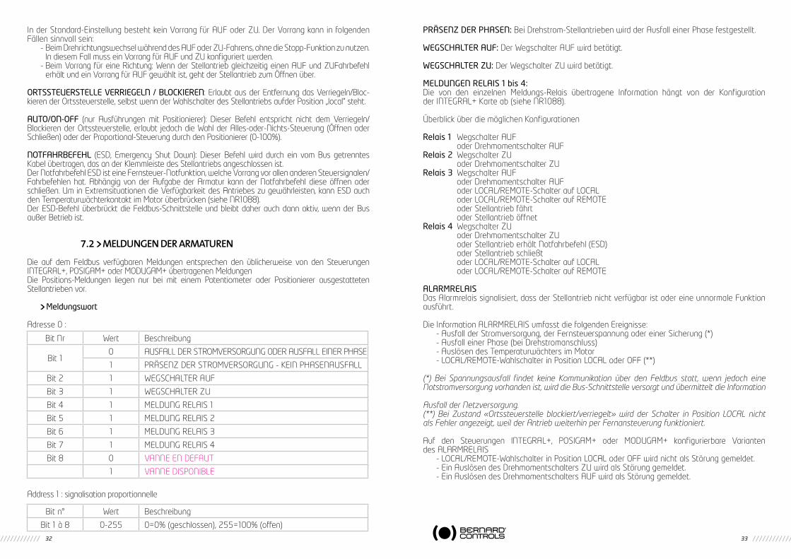
7.2 mELDUNgEN DER ARmATUREN
Die auf dem Feldbus verfügbaren Meldungen entsprechen den üblicherweise von den Steuerungen INTEGRAL+, POSIGAM+ oder MODUGAM+ übertragenen MeldungenDie Positions-Meldungen liegen nur bei mit einem Potentiometer oder Positionierer ausgestatteten Stellantrieben vor.
Meldungswort
Adresse 0 :
Address 1 : signalisation proportionnelle
PRÄSENZ DER PHASEN: Bei Drehstrom-Stellantrieben wird der Ausfall einer Phase festgestellt.
WEGSCHALTER AUF: Der Wegschalter AUF wird betätigt.
WEGSCHALTER ZU: Der Wegschalter ZU wird betätigt.
MELDUNGEN RELAIS 1 bis 4:Die von den einzelnen Meldungs-Relais übertragene Information hängt von der Konfiguration der INTEGRAL+ Karte ab (siehe NR1088).
Überblick über die möglichen Konfigurationen
Relais 1 Wegschalter AUF oder Drehmomentschalter AUFRelais 2 Wegschalter ZU oder Drehmomentschalter ZURelais 3 Wegschalter AUF oder Drehmomentschalter AUF oder LOCAL/REMOTE-Schalter auf LOCAL oder LOCAL/REMOTE-Schalter auf REMOTE oder Stellantrieb fährt oder Stellantrieb öffnetRelais 4 Wegschalter ZU oder Drehmomentschalter ZU oder Stellantrieb erhält Notfahrbefehl (ESD) oder Stellantrieb schließt oder LOCAL/REMOTE-Schalter auf LOCAL oder LOCAL/REMOTE-Schalter auf REMOTE
ALARMRELAISDas Alarmrelais signalisiert, dass der Stellantrieb nicht verfügbar ist oder eine unnormale Funktion ausführt.
Die Information ALARMRELAIS umfasst die folgenden Ereignisse:- Ausfall der Stromversorgung, der Fernsteuerspannung oder einer Sicherung (*)- Ausfall einer Phase (bei Drehstromanschluss)- Auslösen des Temperaturwächters im Motor- LOCAL/REMOTE-Wahlschalter in Position LOCAL oder OFF (**)
(*) Bei Spannungsausfall findet keine Kommunikation über den Feldbus statt, wenn jedoch eine Notstromversorgung vorhanden ist, wird die Bus-Schnittstelle versorgt und übermittelt die Information
Ausfall der Netzversorgung.(**) Bei Zustand «Ortssteuerstelle blockiert/verriegelt» wird der Schalter in Position LOCAL nicht als Fehler angezeigt, weil der Antrieb weiterhin per Fernansteuerung funktioniert.
Auf den Steuerungen INTEGRAL+, POSIGAM+ oder MODUGAM+ konfigurierbare Varianten des ALARMRELAIS
- LOCAL/REMOTE-Wahlschalter in Position LOCAL oder OFF wird nicht als Störung gemeldet.- Ein Auslösen des Drehmomentschalters ZU wird als Störung gemeldet.- Ein Auslösen des Drehmomentschalters AUF wird als Störung gemeldet.
Bit Nr Wert Beschreibung
Bit 10 AUSFALL DER STROMVERSORGUNG ODER AUSFALL EINER PHASE
1 PRÄSENZ DER STROMVERSORGUNG - KEIN PHASENAUSFALL
Bit 2 1 WEGSCHALTER AUF
Bit 3 1 WEGSCHALTER ZU
Bit 4 1 MELDUNG RELAIS 1
Bit 5 1 MELDUNG RELAIS 2
Bit 6 1 MELDUNG RELAIS 3
Bit 7 1 MELDUNG RELAIS 4
Bit 8 0 VANNE EN DEFAUT
1 VANNE DISPONIBLE
Bit n° Wert Beschreibung
Bit 1 à 8 0-255 0=0% (geschlossen), 255=100% (offen)

34 35
1 INTRODUCCION
Profibus DP es un bus de campo que permite conectar servomotores a un sistema de control DCS (Digital Control system) Se pueden conectar sobre una misma línea de bus varios servomotores u otros aparatos que dispongan de un interface correspondiente al bus de campo. El interface Profibus DP descrito en este manual está destinado a los servomotores L.Bernard versión INTEGRAL+, POSIGAM+ o MODUGAM+.Para los servomotores versión INTELLI+ consulte el manual Profibus DPV1 para INTELLI+.Se pueden suministrar cajas con el interface Profibus DP para conectar aparatos que no están preparados.
Bus de campo simple o redundanten
Se puede elegir un bus redundante para obtener una continuidad de comunicación incluso en el caso de que se corte la línea. El DCS debe administrar 2 líneas de bus. El interface servomotor comprende en este caso una tarjeta hija con una entrada adicional aíslada Profibus DP.En caso de fallo en la línea principal el DCS puede comunicarse todavía mediante la línea auxiliar.Según el tipo de bus deseado el servomotor puede estar equipado con un interface INTEGRALBUS simple o redundante.
2 CARACTERÍSTICAS TÉCNICOS
- La tarjeta PROFIBUS-DP esclava puede ser controlada a partir de una tarjeta PROFIBUS-DP maestra: PLC, PC, DCS tarjetas de interface de diferentes proveedores.
- Tipo de soporte físico RS 485.- Velocidad autoadaptadora: 9,6K-1.5M bauds.- direccionamiento de los servomotores de 1 a 99- Número máximo de servomotores conectados en una línea: 31 (hasta 99 con repetidor)- 2 LEDs de estado de bus y 1 LED para la presencia de alimentación.- Aprobado por PNO (Profibus Nutzer Organisation).- Conformidad CE.- Nombre del fichero GSD: versión simple N° LBVS0990.GSD versión redundante N° LBVR0990.GSD- El bus de campo está completamente aislado eléctricamente de los circuitos del servomotor.
En el caso de la versión redundante, cada canal de comunicación está eléctricamente aíslado de los circuitos del servomotor y aislados el uno del otro.
- El corte de alimentación del servomotor no interrumpe la línea de bus.- Las temperaturas de funcionamiento son las del servomotor equipado.
3 INTERFACE PROFIBUS DP
3.1 DESCRIPCIóN DE HARDwARELea las instrucciones de puesta en marcha de INTEGRAL+ (ref. NR1088) antes de empezar
a ajustar el interface INTEGRALBUS.
TR5 315mA 250VFusible F1
Connector J3
Jumper CAV 1
Tarjeta PROFIBUS-DP ‘’INTEGRALBUS’’
Jumpers J1 & J2
36 37
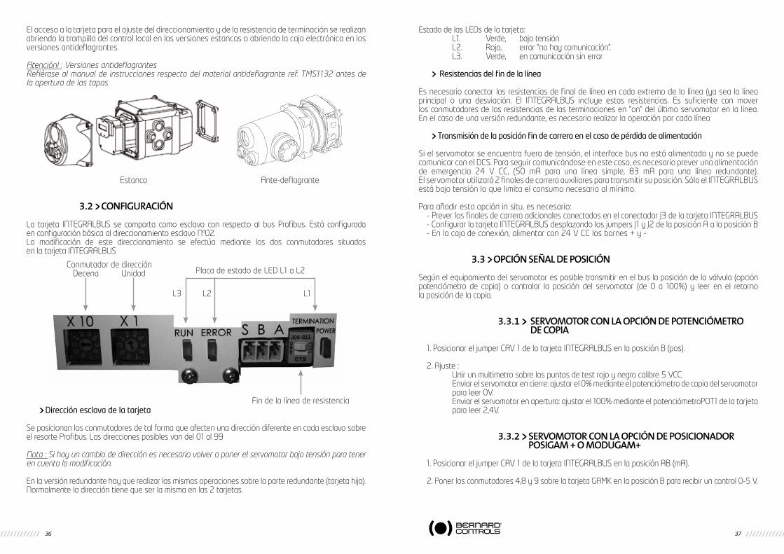
El acceso a la tarjeta para el ajuste del direccionamiento y de la resistencia de terminación se realizan abriendo la trampilla del control local en las versiones estancas o abriendo la caja electrónica en las versiones antideflagrantes.
Atención! : Versiones antideflagrantesRefiérase al manual de instrucciones respecto del material antideflagrante ref. TMS1132 antes de la apertura de las tapas
Estanco Ante-deflagrante
3.2 CONFIgURACIóN
La tarjeta INTEGRALBUS se comporta como esclavo con respecto al bus Profibus. Está configurada en configuración básica al direccionamiento esclavo Nº02.La modificación de este direccionamiento se efectúa mediante los dos conmutadores situados en la tarjeta INTEGRALBUS
Dirección esclava de la tarjeta
Se posicionan los conmutadores de tal forma que afecten una dirección diferente en cada esclavo sobre el resorte Profibus. Las direcciones posibles van del 01 al 99
Nota : Si hay un cambio de dirección es necesario volver a poner el servomotor bajo tensión para tener en cuenta la modificación.
En la versión redundante hay que realizar las mismas operaciones sobre la parte redundante (tarjeta hija). Normalmente la dirección tiene que ser la misma en las 2 tarjetas.
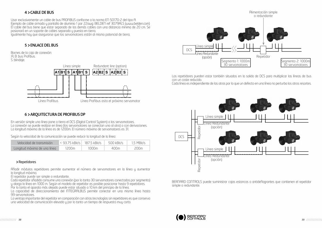
Estado de las LEDs de la tarjeta: L1. Verde, bajo tensión L2. Rojo, error “no hay comunicación”. L3. Verde, en comunicación sin error
Resistencias del fin de la línea
Es necesario conectar las resistencias de final de línea en cada extremo de la línea (ya sea la línea principal o una desviación. El INTEGRALBUS incluye estas resistencias. Es suficiente con mover los conmutadores de las resistencias de las terminaciones en “on” del último servomotor en la línea. En el caso de una versión redundante, es necesario realizar la operación por cada línea
Transmisión de la posición fin de carrera en el caso de pérdida de alimentación
Si el servomotor se encuentra fuera de tensión, el interface bus no está alimentado y no se puede comunicar con el DCS. Para seguir comunicándose en este caso, es necesario prever una alimentación de emergencia 24 V CC, (50 mA para una línea simple, 83 mA para una línea redundante). El servomotor utilizará 2 finales de carrera auxiliares para transmitir su posición. Sólo el INTEGRALBUS está bajo tensión lo que limita el consumo necesario al mínimo.
Para añadir esta opción in situ, es necesario:- Prever los finales de carrera adicionales conectados en el conectador J3 de la tarjeta INTEGRALBUS- Configurar la tarjeta INTEGRALBUS desplazando los jumpers J1 y J2 de la posición A a la posición B- En la caja de conexión, alimentar con 24 V CC los bornes + y -
3.3 OPCIóN SEñAL DE POSICIóN
Según el equipamiento del servomotor es posible transmitir en el bus la posición de la válvula (opción potenciómetro de copia) o controlar la posición del servomotor (de 0 a 100%) y leer en el retorno la posición de la copia.
3.3.1 SERvOmOTOR CON LA OPCIóN DE POTENCIómETRO DE COPIA
1. Posicionar el jumper CAV 1 de la tarjeta INTEGRALBUS en la posición B (pos).
2. Ajuste : Unir un multimetro sobre los puntos de test rojo y negro calibre 5 VCC. Enviar el servomotor en cierre: ajustar el 0% mediante el potenciómetro de copia del servomotor
para leer 0V. Enviar el servomotor en apertura: ajustar el 100% mediante el potenciómetroPOT1 de la tarjeta
para leer 2,4V.
3.3.2 SERvOmOTOR CON LA OPCIóN DE POSICIONADOR POSIgAm + O mODUgAm+
1. Posicionar el jumper CAV 1 de la tarjeta INTEGRALBUS en la posición AB (mA).
2. Poner los conmutadores 4,8 y 9 sobre la tarjeta GAMK en la posición B para recibir un control 0-5 V.
Conmutador de dirección Decena Unidad
Fin de la línea de resistencia
Placa de estado de LED L1 a L2
L1L2L3
38 39
4 CABLE DE BUS
Usar exclusivamente un cable de bus PROFIBUS conforme a la norma EN 50170-2 del tipo A.Ejemplo de cable armado y pantalla de aluminio 1 par 22awg: BELDEN ref 3079ALS (www.belden.com)El cable del bus tiene que estar separado de los demás cables con una distancia mínima de 20 cm. Se posionará en un soporte de cables separado y puesta en tierra.Igualmente hay que asegurarse que los servomotores están al mismo potencial de tierra.
5 ENLACE DEL BUS
Bornes de la caja de conexión::A, B :bus Profibus.S :blindaje.
6 ARQUITECTURA DE PROFIBUS DP
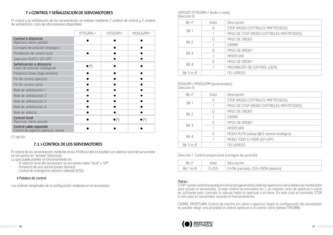
En versión simple una línea pone a tierra el DCS (Digital Control System) a los servomotores.La conexión se puede realizar en línea (los servomotores se conectan uno al otro) o con derivaciones.La longitud máxima de la línea es de 1200m. El número máximo de servomotores es 31.
Según la velocidad de la comunicación se puede reducir la longitud de la línea:
Repetidores
Añadir módulos repetidores permite aumentar el número de servomotores en la línea y aumentar la longitud máxima.El repetidor puede ser simple o redundante.Cada repetidor añadido consume una conexión (por lo tanto 30 servomotores conectados por segmento) y alarga la línea en 1000 m. Según el modelo de repetidor es posible posicionar hasta 9 repetidores.Por lo tanto el aparato más alejado puede estar situado a 10 km del principio de la línea.La capacidad de direccionamiento del INTEGRALBUS permite conectar en una misma línea hasta 99 servomotores.La ventaja importante del repetidor en comparación con otras tecnologías sin repetidores es que conserva una velocidad de comunicación elevada y por lo tanto un tiempo de respuesta muy corto.
Los repetidores pueden estar también situados en la salida de DCS para multiplicar las líneas de bus con un coste reducido.Cada línea es independiente de las otras por lo que un defecto en una línea no perturba los otros resortes.
BERNARD CONTROLS puede suministrar cajas estancas o antideflagrantes que contienen el repetidor simple o redundante.
A1 B1 S A1 B1 S A2 B2 S A2 B2 S
Línea simple Redundant line (option)
Línea Profibus asta el próximo servomotorLínea Profibus
Velocidad de transmisión < 93.75 kBit/s 187.5 kBit/s 500 kBit/s 1,5 MBit/s
Longitud máxima de una línea 1200m 1000m 400m 200m
Alimentación simpleo redundante
DCSLínea simple
Línea Redundante(opción) Repetidor
Segmento 1: 1000m30 servomotores
Segmento 2: 1000m30 servomotores
DCS
Línea simple
Línea simple
Línea Redundante(opción)
Línea Redundante(opción)
Repe
tidor
Repe
tidor
40 41
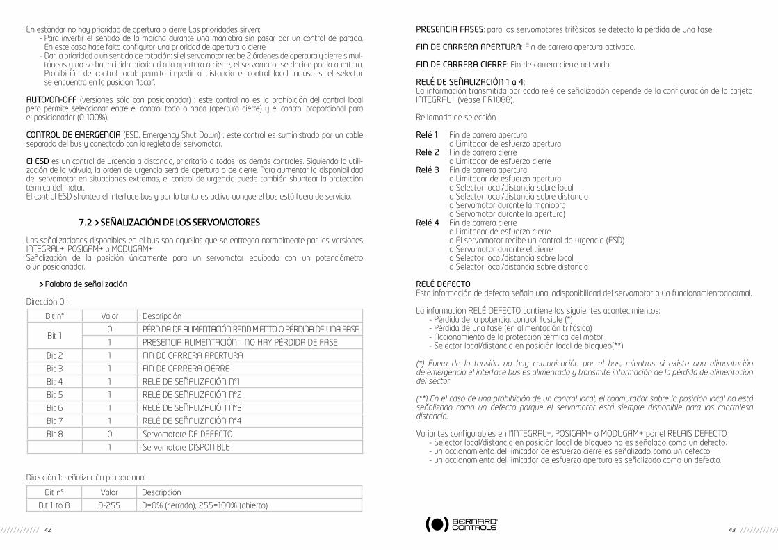
7 CONTROL Y SEñALIZACION DE SERvOmOTORES
El control y la señalización de los servomotores se realizan mediante 2 octetos de control y 2 octetos de señalización. Lista de informaciones disponibles:
(*) opción
7.1 CONTROL DE LOS SERvOmOTORES
El control de los servomotores mediante el bus Profibus sólo es posible si el selector local del servomotor se encuentra en “remote” (distancia).Lo que puede prohibir el funcionamiento es:
- El selector local del servomotor se encuentra sobre “local” u “off”.- Presencia de una alarma (motor térmico)- Control de emergencia externa cableada (ESD)
Palabra de control
Los controle despenden de la configuración realizada en el servomotor.
VERSION INTEGRAL+ (todo o nada)Dirección 0:
POSIGAM / MODUGAM (posicionador)Dirección 0:
Dirección 1: Control proporcional (consigna de posición)
Notas :STOP : si este control se queda en cero (caso general) las órdenes apertura o cierre deben ser mantenidas para activar el servomotor. Si este control se encuentra en 1, un impulso corto de apertura o cierre es suficiente para controlar la válvula hasta la apertura o el cierre. En este caso el comando STOP a cero para el servomotor durante el funcionamiento.
CIERRE, APERTURA: Control de marcha sin cierre o apertura Según la configuración del servomotor es posible elegir una prioridad al control apertura o al control cierre (véase NR1088).
INTEGRAL+ POSIGAM+ MODUGAM+
Control a distanciaApertura, cierre, parada • • •
Consigna de posición analógica • •
Prohibición de control local • • •
Selección AUTO / ON-OFF • •
Señalización a distanciaCopia de posición analógicae • (*) • •
Presencia fases (bajo tensión) • • •
Fin de carrera apertura: • • •
Fin de carrera cierre • • •
Relé de señalización 1 • • •
Relé de señalización 2 • • •
Relé de señalización 3 • • •
Relé de señalización 4 • • •
Relé de defecto • • •
Control localApertura, cierre, parada • • (*) • (*)
Control cable separadoControl de urgencia apertura, cierree • • •
Bit n° Valor Descripción
Bit 10 STOP (MODO CONTROLES MANTENIDOS)
1 PASO DE STOP (MODO CONTROLES MANTENIDOS)
Bit 20 PASO DE ORDEN
1 CIERRE
Bit 30 PASO DE ORDEN
1 APERTURA
Bit 40 PASO DE ORDEN
1 PROHIBICIóN DE CONTROL LOCAL
Bit 5 to 8 - NO USADOS
Bit n° Valor Descripción
Bit 10 STOP (MODO CONTROLES MANTENIDOS)
1 PASO DE STOP (MODO CONTROLES MANTENIDOS)
Bit 20 PASO DE ORDEN
1 CIERRE
Bit 30 PASO DE ORDEN
1 APERTURA
Bit 40 MODO AUTO (véase §8.2 control analógico)
1 MODO TODO O NADA (ON-OFF)
Bit 5 to 8 - NO USADOS
Bit n° Valor Descripción
Bit 1 to 8 0-255 0=0% (cerrado), 255=100% (abierto)
42 43
En estándar no hay prioridad de apertura o cierre Las prioridades sirven:- Para invertir el sentido de la marcha durante una maniobra sin pasar por un control de parada.
En este caso hace falta configurar una prioridad de apertura o cierre- Dar la prioridad a un sentido de rotación: si el servomotor recibe 2 órdenes de apertura y cierre simul-
táneas y no se ha recibido prioridad a la apertura o cierre, el servomotor se decide por la apertura. Prohibición de control local: permite impedir a distancia el control local incluso si el selector se encuentra en la posición “local”.
AUTO/ON-OFF (versiones sólo con posicionador) : este control no es la prohibición del control local pero permite seleccionar entre el control todo o nada (apertura cierre) y el control proporcional para el posicionador (0-100%).
CONTROL DE EMERGENCIA (ESD, Emergency Shut Down) : este control es suministrado por un cable separado del bus y conectado con la regleta del servomotor.
El ESD es un control de urgencia a distancia, prioritario a todos los demás controles. Siguiendo la utili-zación de la válvula, la orden de urgencia será de apertura o de cierre. Para aumentar la disponibilidad del servomotor en situaciones extremas, el control de urgencia puede también shuntear la protección térmica del motor.El control ESD shuntea el interface bus y por lo tanto es activo aunque el bus está fuera de servicio.
7.2 SEñALIZACIóN DE LOS SERvOmOTORES
Las señalizaciones disponibles en el bus son aquellas que se entregan normalmente por las versiones INTEGRAL+, POSIGAM+ o MODUGAM+Señalización de la posición únicamente para un servomotor equipado con un potenciómetro o un posicionador.
Palabra de señalización
Dirección 0 :
Dirección 1: señalización proporcional
PRESENCIA FASES: para los servomotores trifásicos se detecta la pérdida de una fase.
FIN DE CARRERA APERTURA: Fin de carrera apertura activado.
FIN DE CARRERA CIERRE: Fin de carrera cierre activado.
RELÉ DE SEÑALIZACIÓN 1 a 4:La información transmitida por cada relé de señalización depende de la configuración de la tarjeta INTEGRAL+ (véase NR1088).
Rellamada de selección
Relé 1 Fin de carrera apertura o Limitador de esfuerzo aperturaRelé 2 Fin de carrera cierre o Limitador de esfuerzo cierreRelé 3 Fin de carrera apertura o Limitador de esfuerzo apertura o Selector local/distancia sobre local o Selector local/distancia sobre distancia o Servomotor durante la maniobra o Servomotor durante la apertura)Relé 4 Fin de carrera cierre o Limitador de esfuerzo cierre o El servomotor recibe un control de urgencia (ESD) o Servomotor durante el cierre o Selector local/distancia sobre local o Selector local/distancia sobre distancia
RELÉ DEFECTOEsta información de defecto señala una indisponibilidad del servomotor o un funcionamientoanormal.
La información RELÉ DEFECTO contiene los siguientes acontecimientos:- Pérdida de la potencia, control, fusible (*)- Pérdida de una fase (en alimentación trifásica)- Accionamiento de la protección térmica del motor- Selector local/distancia en posición local de bloqueo(**)
(*) Fuera de la tensión no hay comunicación por el bus, mientras sí existe una alimentación de emergencia el interface bus es alimentado y transmite información de la pérdida de alimentación del sector
(**) En el caso de una prohibición de un control local, el conmutador sobre la posición local no está señalizado como un defecto porque el servomotor está siempre disponible para los controlesa distancia.
Variantes configurables en l’INTEGRAL+, POSIGAM+ o MODUGAM+ por el RELAIS DEFECTO- Selector local/distancia en posición local de bloqueo no es señalado como un defecto.- un accionamiento del limitador de esfuerzo cierre es señalizado como un defecto.- un accionamiento del limitador de esfuerzo apertura es señalizado como un defecto.
Bit n° Valor Descripción
Bit 10 PÉRDIDA DE ALIMENTACIóN RENDIMIENTO O PÉRDIDA DE UNA FASE
1 PRESENCIA ALIMENTACIóN - NO HAY PÉRDIDA DE FASE
Bit 2 1 FIN DE CARRERA APERTURA
Bit 3 1 FIN DE CARRERA CIERRE
Bit 4 1 RELÉ DE SEñALIZACIóN N°1
Bit 5 1 RELÉ DE SEñALIZACIóN N°2
Bit 6 1 RELÉ DE SEñALIZACIóN N°3
Bit 7 1 RELÉ DE SEñALIZACIóN N°4
Bit 8 0 Servomotore DE DEFECTO
1 Servomotore DISPONIBLE
Bit n° Valor Descripción
Bit 1 to 8 0-255 0=0% (cerrado), 255=100% (abierto)

BERNARD CONTROLS4 rue d’Arsonval - BP 70091 - 95505 Gonesse Cedex - FranceTel: +33.1. 34.07.71.00 - Fax: +33.1.34.07.71.01E-mail: [email protected]: http://www.bernardcontrols.com
austriaIPU ING PAUL [email protected]. : +43 1 602 41 49
belgiuMBERNARD CONTROLS [email protected]. : +32 (0)2 343 41 22
[email protected] PAULOTel. : +55 11 39 02 26 00
CHinaBERNARD CONTROLS [email protected]él. : +86 (0) 10 6789 2861
CZeCH republiCFLUIDTECHNIK BOHEMIA [email protected]. : +420 548 213 233-5
denMarKARMATEC A/[email protected]. : +45 46 96 00 00
[email protected]. : +203 582 76 47
finlandTALLBERG TECH OY [email protected]. : +358 0 207 420 740
gerManYBERNARD CONTROLS [email protected]. : +49 22 41 98 340
greeCePI&MS Entreprises [email protected]. : +30 210 608 61 52
HungarYAPAGYI TRADEIMPEX [email protected]. : +36 1 223 1958
iranASIA INSTRUMENTS Co. Ltd.info@asiainstrumentsltd.comTEHRANwww.asiainstrumentsltd.comTel. : +98 21 8850 3065
italYBERNARD CONTROLS [email protected] /MILANOTel. : +39 02 931 85 233
MalaYsiaACTUATION & CONTROLS [email protected] BAHRUTel. : +60 7 23 50 277 / 23 50 281
Middle-eastBERNARD [email protected] - U.A.E.Tel. : +971 4 39 80 726
MoroCCoAQUATEL [email protected]. : +212 22 66 55 71
netHerlandsBERNARD CONTROLS BENELUX [email protected] ZWAAGTel. : +31 (0)229-298083
neW ZealandMRCTRANSMARK NZ [email protected] Tel. : +64 9 276 4149
norWaYKSB LINDFLATEN [email protected] LYSAKER Tel. : +476 71 29 900
[email protected]. : +48 22 864 55 43
portugalPINHOL, GOMES & GOMES [email protected]. : +351 21 425 68 50
russiaBERNARD CONTROLS [email protected]/o AMOTEK - MOSCOWMob. : +7 917 562 8591 Tel./Fax : +7 495 343 43 80
russiaA.E.T. (agent)[email protected] PETERSBURGTel./Fax : +7 812 320 55 97Mob. : +7 812 956 35 14
singaporeACTUATION & CONTROLS ENG. (ASIA)[email protected]. : +65 65 654 227
spainBERNARD CONTROLS [email protected]. : +34 91 30 41 139
soutH afriCaA-Q-RATE AUTOMATION [email protected]. : +27 11 432 58 31
soutH KoreaRENTEC CO Ltd (Water market)[email protected]. : +82 31 399 73 23
soutH KoreaYOO SHIN E&I Co. Ltd (Oil & Gas market)[email protected]. : +82 2 406 62 78
sWitZerlandMATOKEM [email protected]. : +41 61 483 15 40
tHailandBERNARD CONTROLSSOUTH-EAST [email protected]. : +66 2 640 82 64
[email protected]. : +90 216 326 39 39
united arabs eMiratesEMIRATES [email protected] DHABITel. : +97 12 644 73 73
united-KingdoMZOEDALE [email protected]. : +44 12 34 83 28 2
usa/Canada/MeXiCoBERNARD CONTROLS [email protected] - TEXASTél. : +1 281 578 66 66


![CATÁLOGO GENERAL FISIOTERAPIA - Physiomed · PÁGINA 71 CARACTERÍSTICAS ESPECIALES DATOS TÉCNICOS ACCESORIOS ESTÁNDAR [1]oquilla ranurada B [1] Instrucciones de manejo [1] Manguera](https://img.pdfslide.us/doc/110x75/5eab45cc3bd386535735f3e8/catlogo-general-fisioterapia-physiomed-pgina-71-caractersticas-especiales.jpg)


![DADOS TÉCNICOS VIRIATO.COM.PT [01.08] TECHNICAL SPEC ... · divisora divider diviseuse divisora teigteilmaschine dados tÉcnicos technical spec. datos tÉcnicos donnÉes techniques](https://img.pdfslide.us/doc/110x75/5e2491ac7c73ba749723b3f8/dados-tcnicos-0108-technical-spec-divisora-divider-diviseuse-divisora-teigteilmaschine.jpg)