Embed Size (px)
Citation preview


Instructions for installation, service and maintenance Flame arresters ADAST
I
CONTENT
1. INTRODUCTION ................................................................................................................................. 1
2. APPLICATION ..................................................................................................................................... 1
3. TECHNICAL DATA, IDENTIFICATION ............................................................................................... 1
3.1 Technical description .................................................................................................................. 1 3.2 Identification ................................................................................................................................ 2 3.3 Technical parameters .................................................................................................................. 2 Flame arresters of line J 34x, J 37x and J 47x are constructed for name explosion pressure PN =
0,6 MPa. ...................................................................................................................................... 3 3.4 Basic parameters ........................................................................................................................ 3 3.5 Summary of flame arresters ........................................................................................................ 3
4. INSTRUCTIONS FOR THE SAFETY OF WORK ............................................................................... 4
4.1 Safety of the equipment design ................................................................................................... 4 4.2 Operation safety .......................................................................................................................... 4
5. TRANSPORT ...................................................................................................................................... 4
6. INSTALLATION ................................................................................................................................... 4
6.1 The application of the detonation flame arresters as piping deflagration ones ........................... 5 6.2 Detonation piping flame arresters ............................................................................................... 6
7. OPERATING INFORMATION ............................................................................................................. 6
8. MAINTENANCE AND REPAIRS ......................................................................................................... 6
9. STORAGE ........................................................................................................................................... 7
10. LIST OF SPARE PARTS ..................................................................................................................... 7
11. ACCESSORIES ................................................................................................................................... 7
12. DISASSEMBLY AND DISPOSAL ........................................................................................................ 7
13. GUARANTEE AND RECLAMATION .................................................................................................. 7
14. ENCLOSURE ...................................................................................................................................... 7
15. LIST OF CERTIFICATES .................................................................................................................... 8

Instructions for installation, service and maintenance
1
1. INTRODUCTION
The instructions for installation, service and maintenance provide the User with information on the product, its design, installation, proper service and maintenance.
It is equipment operating in the explosion-proof area. An authorised, properly trained person obliged to adhere to safety regulations shall carry out the installation in the process equipment (e.g. pumping stations).
The equipment can be put into operation after the inspection process of the filling station equipment completion and when a respective inspection body approves the operation.
SAVE FOR FURTHER USE!
2. APPLICATION
The flame arresters are used as a protection against the spreading of flame into the guarded part of the equipment. It is above all the safety protection of the process equipment applied for the storage, distribution, transport and processing of flammable gases and vapours of liquids of IIA explosion class and a part of IIB, IIB3 class assortment (bi-directional detonation flame arresters).
Their design results from the type of safety protection – against deflagration or detonation.
Deflagration flame arresters are fittings intended to block and extinguish deflagration i.e. subsonic spreading of flame without considerable pressure wave. As far as their application is concerned the flame arresters can be classified as follows:
a) terminal deflagration ones - type J 373, J 374 series
b) terminal deflagration valves (aerating piping of fuel tanks, etc.) - type J 341, J 344 series
c) deflagration piping - type J 474 series
Detonation flame arresters are fittings installed in the piping and preventing flashback of flame during detonation burning and subsequent pressure wave propagating by supersonic speed. Type series:
– J 131, J 134 (bi-directional detonation ones)
– J 474 (unidirectional detonation ones, they work as deflagration ones in reverse direction)
3. TECHNICAL DATA, IDENTIFICATION
3.1 Technical description
The technical data are specified in technical sheets for single types of flame arresters.
The flame arresters of IIA explosion class are equipped with an all-stainless capillary flame arrester element provided with coils with capillary gap 0,7 mm or 0,4 mm.
The bi-directional detonation flame arresters of IIB explosion class, are equipped with an all-stainless capillary flame arrester element provided with discs of capillary gap 0,4 mm.
Construction parts of the flame element are from stainless steel.
The corner detonation flame arresters J 474 are equipped with a eliminator of detonation located in front of the flame arrester element. In case of the bi-directional flame arresters J 131 these eliminators of detonation are located at both sides. The design of the eliminator of detonation allows suppressing the shock weave in case of detonation and thus preventing the damage of the flame arrester element.
Some types of detonation flame arrester are not equipped with the eliminator of detonation.
Standard flame arrester housings and covers of deflagration flame arresters, incl. the J 474 type, are made of malleable cast iron. Only with valves ND 50 the cover with built-in safety valve and
Instructions for installation, service and maintenance
2
underpressure valve are made of aluminium alloy. The detonation flame arresters of type J 131 and J 134 series including the flame arrester housings are all-stainless.
The all-stainles flame arresters are made from corrosion-proof steel for casting 422931 and eliminators of detonation of J 131.25 flame arrester from 17347 steel.
The all-stainless flame arresters in aggressive atmosphere (in chemical industry) we recommend to consult with flame arresters producer.
Surface preservation – external surfaces of the flame arresters are coated with yellow chromium paint, 6400 hue.
Design of the flame arresters – shape, principal and connecting dimensions are specified in the Annex. No.1.
The flame arresters of all type series comply within full range with the EN 12874 standard
considering the design, function requirements, limits of application and testing.
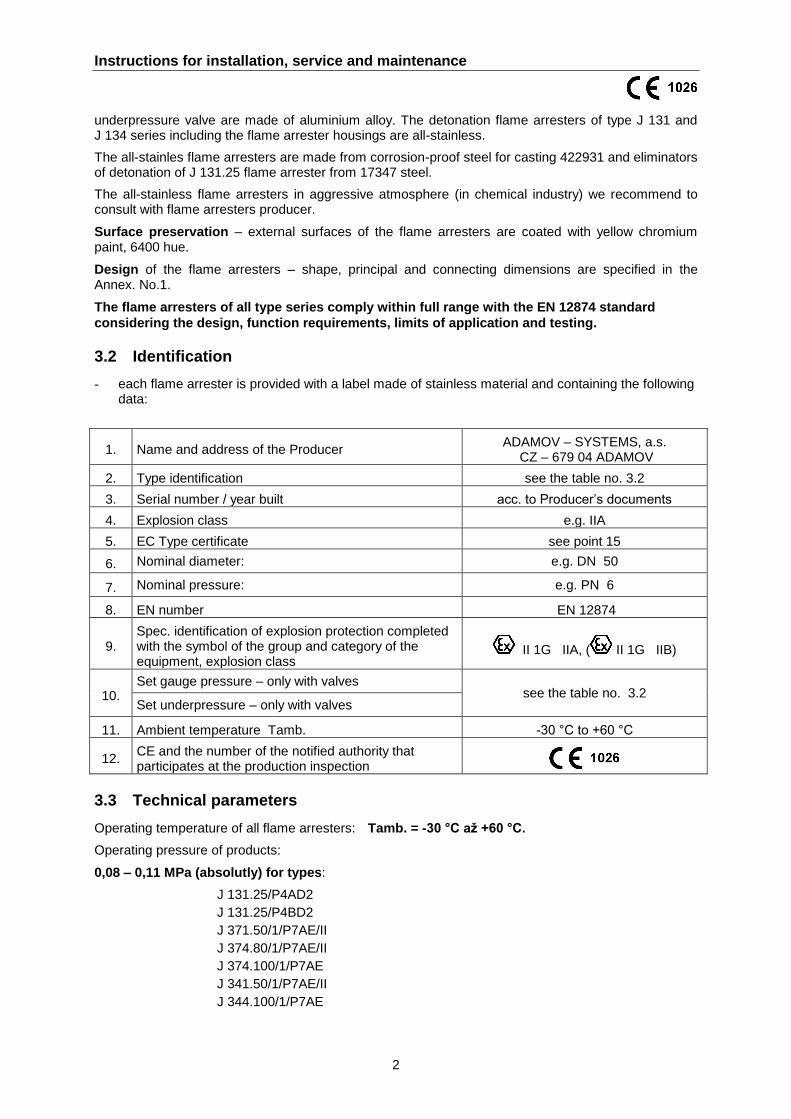
3.2 Identification
- each flame arrester is provided with a label made of stainless material and containing the following data:
1. Name and address of the Producer ADAMOV – SYSTEMS, a.s.
CZ – 679 04 ADAMOV
2. Type identification see the table no. 3.2
3. Serial number / year built acc. to Producer’s documents
4. Explosion class e.g. IIA
5. EC Type certificate see point 15
6. Nominal diameter: e.g. DN 50
7. Nominal pressure: e.g. PN 6
8. EN number EN 12874
9. Spec. identification of explosion protection completed with the symbol of the group and category of the equipment, explosion class
II 1G IIA, ( II 1G IIB)
10. Set gauge pressure – only with valves
see the table no. 3.2 Set underpressure – only with valves
11. Ambient temperature Tamb. -30 °C to +60 °C
12. CE and the number of the notified authority that participates at the production inspection
3.3 Technical parameters
Operating temperature of all flame arresters: Tamb. = -30 °C až +60 °C.
Operating pressure of products:
0,08 – 0,11 MPa (absolutly) for types:
J 131.25/P4AD2
J 131.25/P4BD2
J 371.50/1/P7AE/II
J 374.80/1/P7AE/II
J 374.100/1/P7AE
J 341.50/1/P7AE/II
J 344.100/1/P7AE
Instructions for installation, service and maintenance
3
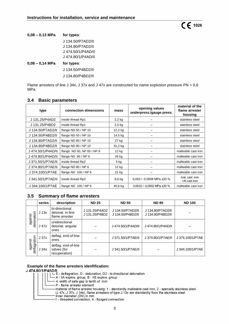
0,08 – 0,13 MPa for types:
J 134.50/P7AD2/II
J 134.80/P7AD2/II
J 474.50/1/P4AD/II
J 474.80/1/P4AD/II
0,08 – 0,14 MPa for types:
J 134.50/P4BD2/II
J 134.80/P4BD2/II
Flame arresters of line J 34x, J 37x and J 47x are constructed for name explosion pressure PN = 0,6 MPa.
3.4 Basic parameters
type connection dimensions mass opening values
underpress./gauge press.
material of the
flame arrester
housing
J 131.25/P4AD2 inside thread Rp1 2,2 kg – stainless steel
J 131.25/P4BD2 inside thread Rp1 2,5 kg – stainless steel
J 134.50/P7AD2/II flange ND 50 / NP 10 12,2 kg – stainless steel
J 134.50/P4BD2/II flange ND 50 / NP 10 14,5 kg – stainless steel
J 134.80/P7AD2/II flange ND 80 / NP 10 27 kg – stainless steel
J 134.80/P4BD2/II flange ND 80 / NP 10 31,2 kg – stainless steel
J 474.50/1/P4AD/II flange ND 50, NP 65 / NP 6 12 kg – malleable cast iron
J 474.80/1/P4AD/II flange ND 80 / NP 6 26 kg – malleable cast iron
J 371.50/1/P7AE/II inside thread Rp2 5 kg – malleable cast iron
J 374.80/1/P7AE/II flange ND 80 / NP 6 12 kg – malleable cast iron
J 374.100/1/P7AE flange ND 100 / NP 6 21 kg – malleable cast iron
J 341.50/1/P7AE/II inside thread Rp2 8,6 kg 0,003 / -0,0008 MPa ±20 % mal. cast iron +Al cast iron
J 344.100/1/P7AE flange ND 100 / NP 6 40,6 kg 0,0015 / -0,0002 MPa ±20 % malleable cast iron
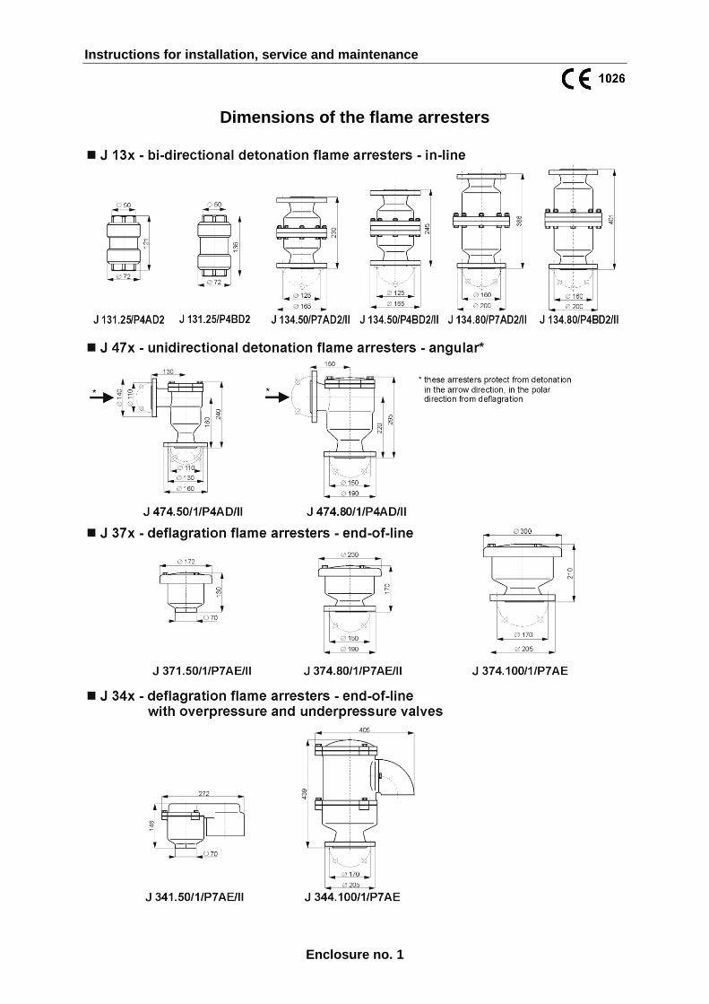
3.5 Summary of flame arresters
series description ND 25 ND 50 ND 80 ND 100
ag
ain
st
de
ton
atio
n
J 13x bi-directional detonat. in-line flame arrester
J 131.25/P4AD2 J 131.25/P4BD2
J 134.50/P7AD2/II J 134.50/P4BD2/II
J 134.80/P7AD2/II J 134.80/P4BD2/II
–
J 47x unidirectional detonat. angular ones
– J 474.50/1/P4AD/II J 474.80/1/P4AD/II –
ag
ain
st
de
fla
gra
tio
n
J 37x deflag. end-of-line ones
– J 371.50/1/P7AE/II J 374.80/1/P7AE/II J 374.100/1/P7AE
J 34x deflag. end-of-line valves (for recuperation)
– J 341.50/1/P7AE/II – J 344.100/1/P7AE
Example of the flame arresters idenfification:
Instructions for installation, service and maintenance
4
4. INSTRUCTIONS FOR THE SAFETY OF WORK
The flame arresters are safety equipment and shall be always interconnected conductively in the process equipment and grounded in accordance with the CENELEC and R044-001 standards.
4.1 Safety of the equipment design
The Producer guarantees safety of the design.
The design of the flame arresters complies with the requirements of EN 12874 and has been
approved for the operation in the area characterised by II1 G IIA , ( II1 G IIB) symbols
shown on the guard label. Considering safety of operation in the area with the danger of
explosion the flame arrester has been EC type tested (certification) according to the Annex III.
of the rule 94/9/EC – ATEX by notified authority No. 1026: AO 210 Fyzikálně technický zkušební
ústav, s.p.,
Pikartská 7, 716 07 Ostrava - Radvanice.
The Producer can submit a copy of the EC Type Inspection Certificate on demand of authorised
authorities.
4.2 Operation safety
The pumping station User or the process equipment User is responsible for the operation safety.
The User is obliged to mark the hazardous area with warning symbols (No smoking, No open fire, etc.).
The User is responsible for drawing up the regulations with terms of regular inspections. The
Producer recommends carrying out inspections respectively according to operating
conditions, but once a year at least. A serviceman trained by the Producer for service works
and provided with valid certificate for this activity (Producer’s Certificate for Service
Authorisation) can only carry out the service works. The serviceman must not break the
operation and fire safety in the course of these repairs and other activities.
He confirms the performed inspection in the “Record of Inspection and Cleaning of Flame
Arresters” which is filed with the User. After the inspection and reinstallation he shall secure
the guard by an inspection seal with a serial number (identification sign) against unauthorised
handling.
5. TRANSPORT
The Customer provides the transport from the Producer in the Contract. If the Producer provides the transport, he delivers the product to the contractual point of delivery. The Produces is sufficiently familiar with the method of handling and transportation. If the Customer provides the transport, the Producer provides professional loading. He is not responsible for the transportation method. The product shall be secured against damage, displacement and upsetting on the means of transport.
6. INSTALLATION
Only a worker trained by the Producer of the equipment for the installation and service who keeps valid certificate (Producer’s certificate for service authorisation) for this activity can carry out this installation.
The flame arresters are installed according to the method specified in the design. Unidirectional
detonation flame arresters (J 47x) are installed so that the socket with the eliminator of
detonation is in the direction to presumed detonation. The detonation flame arresters have eliminators of detonation on the outlet and the inlet and can be installed with any socket in the direction of the presumed detonation. These flame arresters can be installed either in vertical or horizontal position.
End-of-line deflagration flame arresters – type J 37x.xx and deflagration valve flame arresters – type J 34x.xx are always installed in vertical position.
Instructions for installation, service and maintenance
5
They are either threaded or flanged with a gasket. Tightness test of the connection shall be always carried out after the installation of the flame arresters in the process equipment to prove the safety of the equipment. The tightness test is specified in the project design.
The conditions for the application and operation of the flame arresters shall comply with the
articles 6.4.1, 6.4.2 and 6.4.4 EN 12874.
Operating temperature and pressure of the flowing medium (gases, vapours) shall comply with
the values on the flame arrester label, see the point 3.3 – TECHNICAL PARAMETERS.
The flame arresters should not be located close to hot equipment.
6.1 The application of the detonation flame arresters as piping deflagration
ones
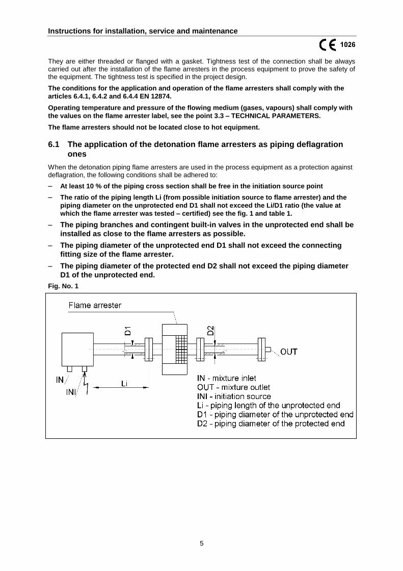
When the detonation piping flame arresters are used in the process equipment as a protection against deflagration, the following conditions shall be adhered to:
– At least 10 % of the piping cross section shall be free in the initiation source point
– The ratio of the piping length Li (from possible initiation source to flame arrester) and the
piping diameter on the unprotected end D1 shall not exceed the Li/D1 ratio (the value at
which the flame arrester was tested – certified) see the fig. 1 and table 1.
– The piping branches and contingent built-in valves in the unprotected end shall be
installed as close to the flame arresters as possible.
– The piping diameter of the unprotected end D1 shall not exceed the connecting
fitting size of the flame arrester.
– The piping diameter of the protected end D2 shall not exceed the piping diameter
D1 of the unprotected end.
Fig. No. 1
Instructions for installation, service and maintenance
6
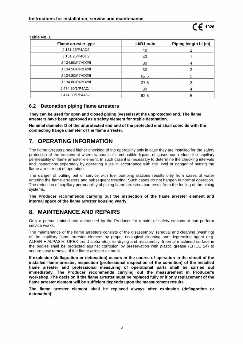
Table No. 1
Flame arrester type Li/D1 ratio Piping length Li (m)
J 131.25/P4AD2 40 1
J 131.25/P4BD2 40 1
J 134.50/P7AD2/II 80 4
J 134.50/P4BD2/II 60 3
J 134.80/P7AD2/II 62,5 5
J 134.80/P4BD2/II 37,5 3
J 474.50/1/P4AD/II 80 4
J 474.80/1/P4AD/II 62,5 5
6.2 Detonation piping flame arresters
They can be used for open and closed piping (vessels) at the unprotected end. The flame
arresters have been approved as a safety element for stable detonation.
Nominal diameter D of the unprotected end and of the protected end shall coincide with the
connecting flange diameter of the flame arrester.
7. OPERATING INFORMATION
The flame arresters need higher checking of the operability only in case they are installed for the safety protection of the equipment where vapours of combustible liquids or gases can reduce the capillary permeability of flame arrester element. In such case it is necessary to determine the checking intervals and inspections separately by operating rules in accordance with the level of danger of putting the flame arrester out of operation.
The danger of putting out of service with fuel pumping stations results only from cases of water entering the flame arresters and subsequent freezing. Such cases do not happen in normal operation. The reduction of capillary permeability of piping flame arresters can result from the fouling of the piping systems.
The Producer recommends carrying out the inspection of the flame arrester element and
internal space of the flame arrester housing yearly.
8. MAINTENANCE AND REPAIRS
Only a person trained and authorised by the Producer for repairs of safety equipment can perform service works.
The maintenance of the flame arresters consists of the disassembly, removal and cleaning (washing) of the capillary flame arrester element by proper ecological cleaning and degreasing agent (e.g. ALFER + ALPASIV, UPEX trend alpha etc.), its drying and reassembly. Internal machined surface in the bodies shall be protected against corrosion by preservation with plastic grease (LITOL 24) to secure easy removal of the flame arrester element.
If explosion (deflagration or detonation) occurs in the course of operation in the circuit of the
installed flame arrester, inspection (professional inspection of the condition) of the installed
flame arrester and professional measuring of operational parts shall be carried out
immediately. The Producer recommends carrying out the measurement in Producer’s
workshop. The decision if the flame arrester must be replaced fully or if only replacement of the
flame arrester element will be sufficient depends upon the measurement results.
The flame arrester element shall be replaced always after explosion (deflagration or
detonation)!
Instructions for installation, service and maintenance
7
9. STORAGE
The flame arresters shall be stored in sheltered rooms. It is always necessary to blind the inlet and outlet sockets to prevent the entering of mechanical impurities into internal space of flame arresters. The sockets are blinded when delivered from the Producer.
10. LIST OF SPARE PARTS
The Producer shall supply service parts on the basis of an order. The Producer also supplies relevant commercial and technical documentation, if requested. The list of parts recommended as spare parts for individual types of the flame arresters is the Annex No. 2 and 3 to the present instructions.
11. ACCESSORIES
The delivery includes: - Instructions for installation, service and maintenance
- EC Declaration of Conformity
12. DISASSEMBLY AND DISPOSAL
The product does not contain materials detrimental to ecology. It is necessary to avoid the contact with oil or other combustible residual matters in the course of disposal. The worker shall be equipped with protective safety aids. In case of the pollution of hands e.g., they shall be washed with hot water and soap and greased with protective cream.
13. GUARANTEE AND RECLAMATION The guarantee and the method of reclamation are given in the Contract. When setting up a claim the following shall be specified:
- serial number and the type of the flame arrester - description of the defect or failure - description of the defect or failure occurrence
The defects due to incorrect checking and maintenance are not an object of reclamation and they shall not be accepted. Reclamation shall not be also accepted due to incorrect design or wrong installation in the equipment.
If not specified otherwise in the Contract, the guarantee period is six months since the date of taxable supplies specified in the relevant invoice.
14. ENCLOSURE
Enclosure No. 1 – Dimensions of flame arresters
Enclosure No. 2 - 3 – List of spare parts
Instructions for installation, service and maintenance
8
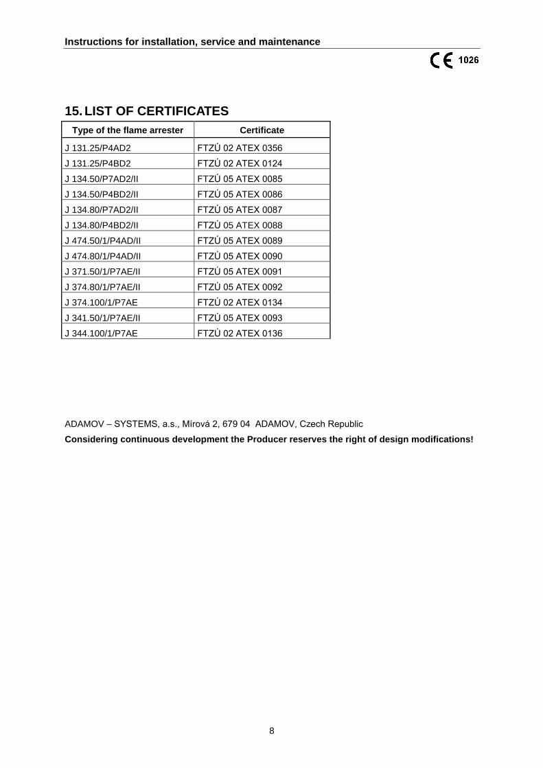
15. LIST OF CERTIFICATES
Type of the flame arrester Certificate
J 131.25/P4AD2 FTZÚ 02 ATEX 0356
J 131.25/P4BD2 FTZÚ 02 ATEX 0124
J 134.50/P7AD2/II FTZÚ 05 ATEX 0085
J 134.50/P4BD2/II FTZÚ 05 ATEX 0086
J 134.80/P7AD2/II FTZÚ 05 ATEX 0087
J 134.80/P4BD2/II FTZÚ 05 ATEX 0088
J 474.50/1/P4AD/II FTZÚ 05 ATEX 0089
J 474.80/1/P4AD/II FTZÚ 05 ATEX 0090
J 371.50/1/P7AE/II FTZÚ 05 ATEX 0091
J 374.80/1/P7AE/II FTZÚ 05 ATEX 0092
J 374.100/1/P7AE FTZÚ 02 ATEX 0134
J 341.50/1/P7AE/II FTZÚ 05 ATEX 0093
J 344.100/1/P7AE FTZÚ 02 ATEX 0136
ADAMOV – SYSTEMS, a.s., Mírová 2, 679 04 ADAMOV, Czech Republic
Considering continuous development the Producer reserves the right of design modifications!
Instructions for installation, service and maintenance
Enclosure no. 1
Dimensions of the flame arresters

Instructions for installation, service and maintenance
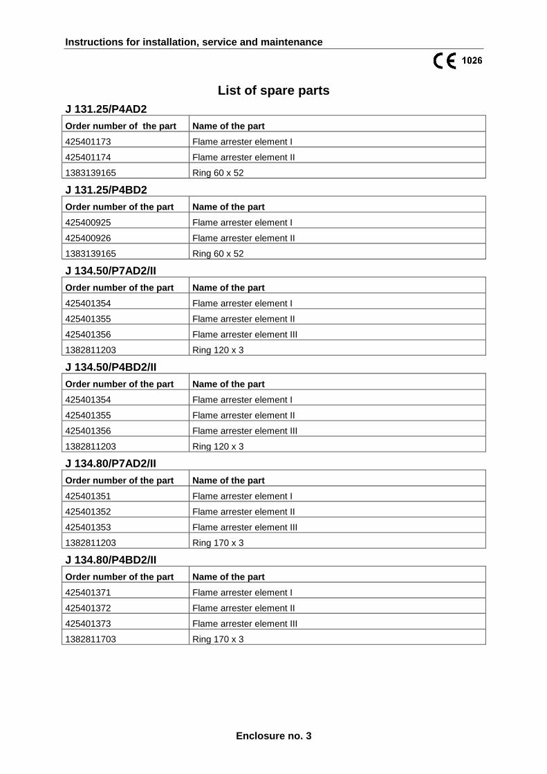
Enclosure no. 3
List of spare parts
J 131.25/P4AD2
Order number of the part Name of the part
425401173 Flame arrester element I
425401174 Flame arrester element II
1383139165 Ring 60 x 52
J 131.25/P4BD2
Order number of the part Name of the part
425400925 Flame arrester element I
425400926 Flame arrester element II
1383139165 Ring 60 x 52
J 134.50/P7AD2/II
Order number of the part Name of the part
425401354 Flame arrester element I
425401355 Flame arrester element II
425401356 Flame arrester element III
1382811203 Ring 120 x 3
J 134.50/P4BD2/II
Order number of the part Name of the part
425401354 Flame arrester element I
425401355 Flame arrester element II
425401356 Flame arrester element III
1382811203 Ring 120 x 3
J 134.80/P7AD2/II
Order number of the part Name of the part
425401351 Flame arrester element I
425401352 Flame arrester element II
425401353 Flame arrester element III
1382811203 Ring 170 x 3
J 134.80/P4BD2/II
Order number of the part Name of the part
425401371 Flame arrester element I
425401372 Flame arrester element II
425401373 Flame arrester element III
1382811703 Ring 170 x 3
Instructions for installation, service and maintenance
Enclosure no. 3
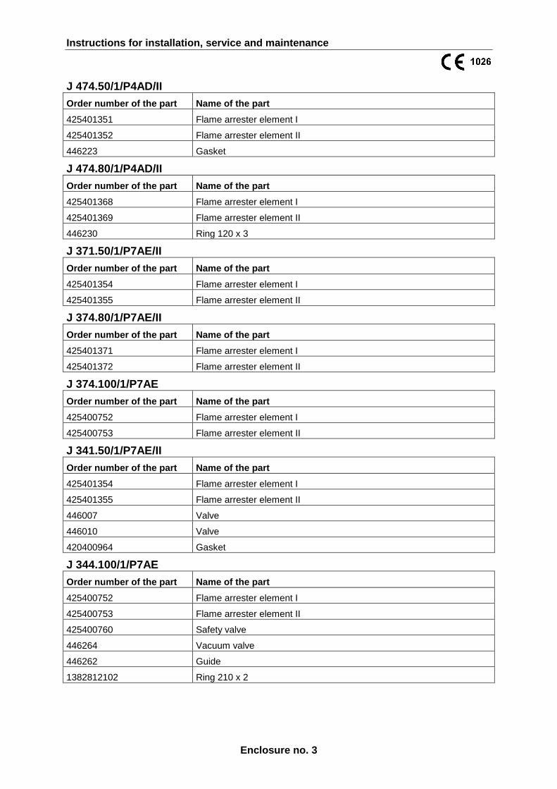
J 474.50/1/P4AD/II
Order number of the part Name of the part
425401351 Flame arrester element I
425401352 Flame arrester element II
446223 Gasket
J 474.80/1/P4AD/II
Order number of the part Name of the part
425401368 Flame arrester element I
425401369 Flame arrester element II
446230 Ring 120 x 3
J 371.50/1/P7AE/II
Order number of the part Name of the part
425401354 Flame arrester element I
425401355 Flame arrester element II
J 374.80/1/P7AE/II
Order number of the part Name of the part
425401371 Flame arrester element I
425401372 Flame arrester element II
J 374.100/1/P7AE
Order number of the part Name of the part
425400752 Flame arrester element I
425400753 Flame arrester element II
J 341.50/1/P7AE/II
Order number of the part Name of the part
425401354 Flame arrester element I
425401355 Flame arrester element II
446007 Valve
446010 Valve
420400964 Gasket
J 344.100/1/P7AE
Order number of the part Name of the part
425400752 Flame arrester element I
425400753 Flame arrester element II
425400760 Safety valve
446264 Vacuum valve
446262 Guide
1382812102 Ring 210 x 2