Embed Size (px)
Citation preview

Instructions for installation and use(to be kept in a safe place)
English : page .........................................................................................19
EN

Garantie
Mise au rebut du produit - Protection de l’environnement :
Conformément aux exigences de la directive DEEE - 2002/96/CE (Déchets d’Équipements
Électriques et Électroniques), les produits électriques et électroniques usagés doivent être détruits séparément des ordures ménagères normales afi n de promouvoir la réutilisation, le recyclage et d’autres formes de récupération, ainsi que de limiter
la quantité de déchets devant être éliminés et de réduire du même coup les décharges.
Lorsque vous vous débarrasserez de ce produit, respectez les prescriptions locales pour l’élimination des déchets. Ne le jetez pas dans la nature, mais remettez- le à un centre de collecte spécialisé de rebuts électriques et électroniques et/ou renseignez-vous auprès de votre revendeur lors de l’achat d’un nouveau produit.
10
!
PrincipeSauf dispositions contraires, nous garantissons contractuellement le bon fonctionnement de nos Produits neufs. Nous garantissons que nos Pro-duits correspondent à leurs spécifi cités techniques et sont exempts de défaut de matière ou de fabrication.En tout état de cause, la présente garantie est limitée, à notre conve-nance, soit à la remise en état ou l’échange par un Produit neuf ou re-conditionné, soit au remboursement des Produits reconnus défectueux par nous. Les frais de port et d’expédition du Produit réparé ou remplacé et livré à notre Client sont à notre charge, à l’exclusion des frais de main d’œuvre, déplacement et/ou de séjour engagés par nous à l’occasion des réparations opérées en dehors de la France Métropolitaine et à l’exclu-sion de tout versement de dommages et intérêts. Tout retour de Produit doit être préalablement décidé et accepté par nous. Aucun retour d’offi ce sur l’initiative de notre Client ne sera accepté.Plus spécialement, la garantie des pièces détachées ne pourra jouer qu’après analyse et expertise par notre société des pièces retournées puis décision de changement de ces pièces.En tout état de cause, la garantie légale du vendeur continue à s’appli-quer.Pour que la garantie soit acquise, notre Client et l’Utilisateur fi nal s’enga-gent à respecter les paramètres de l’équilibre de l’eau de la piscine selon les critères suivants : - pH : 6,8 < pH < 7,6- chlore libre (*) : < 3,0 mg/L- brome total (*) : < 5,0 mg/L- stabilisant (si utilisé) : < 75 mg/L- métaux dissous totaux (fer, manganèse, cuivre, zinc…) : < 0,1 mg/L (*) : Les nettoyeurs doivent impérativement être retirés du bassin lors d’un traitement de choc.Remarque : L’usage de l’eau d’un forage et/ou d’un puits est proscrit.
Limitations généralesLa présente garantie ne joue pas pour les vices apparents, c’est à dire les défauts d’aspect visibles non déclarés par notre Client lors de la livraison des Produits.Sont également exclus les défauts ou détériorations provoqués par une inadéquation du Produit au regard des besoins de l’Utilisateur fi -nal, par l’usure normale, par une négligence, par une mauvaise instal-lation ou une utilisation non conforme aux recommandations fi gurant sur la notice de l’appareil, par un entretien insuffi sant et/ou un acci-dent de manipulation, par un mauvais stockage, et/ou par les études, instructions et/ou spécifi cations émanant de notre Client.Tous travaux de modifi cation effectués sur les Produits par notre Client, par l’Utilisateur fi nal ou par un tiers mettent fi n automatique-
ment à la garantie dans son intégralité. Il en est de même pour les cas où des pièces d’origines auraient été remplacées par des pièces qui ne sont pas vendues par nousNotre Client devra par ailleurs s’assurer de la compatibilité de nos Produits avec les autres équipements du bassin auprès des différents fabricants concernés, ainsi que des règles d’installation et de mise en route à respecter pour le bon fonctionnement de l’ensemble du système.En cas de retour du Produit en notre atelier, les frais de transport al-ler-retour seront à la charge de l’Utilisateur fi nal, à l’exception de ceux mentionnés dans le paragraphe 2 du présent article.L’immobilisation et la privation de jouissance d’un appareil en cas de réparation éventuelle ne sauraient donner lieu à indemnités. La présente garantie sera enfi n exclue en cas de défaut ou retard de paiement du Produit concerné par notre Client.
DuréeLa date déterminant le point de départ de la garantie contractuelle est celle fi gurant sur la facture de vente du Produit neuf par notre Client à l’Utilisateur fi nal. La facture est exigible et conditionne toute prise en charge sous ga-rantie. A défaut, notre Client supportera seul l’intégralité des conséquences dommageables pour notre société, pour toute réclamation d’Utilisa-teur fi nal au titre de la garantie contractuelle postérieure à sa date d’expiration.Les réparations et/ou remplacements effectués en exécution de la présente garantie n’auront en aucun cas pour effet d’en prolonger ou d’en renouveler la durée.
Dispositions particulières pour les Produits de la Gamme Electrolyseur au Sel et RégulationSur l’ensemble de la gamme des électrolyseurs au sel, la garantie est totale et inconditionnelle : quelles que soient les causes de leur dé-térioration, boitier de commande et cellule seront remis en état ou changés durant la période de garantie.La durée de cette garantie est de 2 ans à compter de la date de la facture de vente du Produit neuf par notre Client à l’Utilisateur fi nal.Sur la gamme TRi, la période de garantie est étendue à 3 ans (hors modules optionnels « TRi pH » et « TRi PRO »).Sur l’ensemble des Produits, la garantie n’est accordée qu’à la condi-tion de l’installation par un professionnel, à l’exception de la gamme d’électrolyseurs Ei.Remarque : Cette garantie inconditionnelle ne s’applique pas dans le cas de la gamme des régulations (pH Perfect, modules TRi pH et TRi PRO).
Enregistrez votre produit sur notre site Internet :- Soyez les premiers à être informés des nouveautés Zodiac et de nos promotions.
- Aidez-nous à améliorer sans cesse la qualité de nos produits.
www.zodiac-poolcare.com
Toutes les demandes de prise en garantie doivent être adresséesà votre détaillant. Nous vous recommandons de garder précieusement votre facture d’achat pour toute assistance sur votre produit.
18
Thank you for choosing the Ei chlorine generator for your pool maintenance.
From now on your pool will be only a source of relaxation and wellbeing, as your Ei will free you of the tedious manual treatment whilst providing healthy, clear and more natural water throughout the season.
We recommend that you read this User Manual carefully before installing and using your Ei salt water chlorinator.
Contents
Package contents page 20
Recommendations page 21
Installation and user guide page 223.1 Installing the Ei power pack .................................................................................................................................................................................................................... 223.2 Ei cell installation ...............................................................................................................................................................................................................................................233.3 Flow meter installation.................................................................................................................................................................................................................................243.4 Ei power pack connection ........................................................................................................................................................................................................................ 25
Ei salt chlorinator parametering page 254.1 Ei power pack description ......................................................................................................................................................................................................................... 254.2 Language selection ..........................................................................................................................................................................................................................................264.3 Setting the clock (clock) .............................................................................................................................................................................................................................264.4 Setting the timer ................................................................................................................................................................................................................................................274.5 Manual start-up .................................................................................................................................................................................................................................................. 284.6 External clock use (fi ltration control box) .............................................................................................................................................................................. 284.7 Setting chlorine production .................................................................................................................................................................................................................... 28
Connecting to an external timer (home automation) page 295.1 Setting the type of external timer .................................................................................................................................................................................................... 295.2 Precautions when wiring an external controller............................................................................................................................................................... 295.4 Checking wiring and connections .................................................................................................................................................................................................... 30
Water balance page 31
Error and warning messages page 317.1 ‘CHECK SALT’ ............................................................................................................................................................................................................................................................317.2 ‘NO FLOW‘ ....................................................................................................................................................................................................................................................................317.3 ‘OUTPUT FAULT’ ..................................................................................................................................................................................................................................................327.4 ‘TEST CELL’ ...............................................................................................................................................................................................................................................................327.5 «INVERSION» .........................................................................................................................................................................................................................................................32
Safety page 32
Maintenance page 339.1 Inspecting and cleaning the electrode ..........................................................................................................................................................................................339.2 Battery / memory ..............................................................................................................................................................................................................................................339.3 Maintenance / Wintering ............................................................................................................................................................................................................................33
Warranty page 34
1
2
3
4
5
6
7
8
9
10
19
19
EN

Package contents
1 1 x Ei power pack
2 1 x wall mount with fi xing kit
3 1 x fl ow detector kit (detector, tefl on, adapter & adapter ring)
4 1 x reducer for DN 50 mm piping (Installed in the ring of the Ei cell)
5 1 x reducer for 1 1/2 ‘’ piping with pressure seal (‘UK’ English version)
6 1 x Ei cell with ‘Quick Fix’ hose clamp
7 1 x 22 mm diameter cylinder saw (Ei cell and fl ow sensor installation)
1
1
2
3
4
5
6
7
20
Recommendations
Important information
PLEASE READ THIS INFORMATION BEFORE INSTALLING. YOU SHOULD ALWAYS READ THE INSTALLATION GUIDE BEFORE OPERATING THE APPLIANCE. WE ADVISE YOU TO KEEP YOUR INSTALLATION GUIDE.
Zodiac believes in safety fi rst
At Zodiac, we take safety seriously. Always exercise caution when using electrical appliances and follow the instructions. Failure to do so could result in permanent injury, electrocution or drowning.
Your TRi / Ei salt chlorinator has been tested and approved as being in compliance with the norm IP23.
It satisfi es the European safety norms required for electrical appliances.
Connection to the electric mains and positioning of the different elements with respect to the pool must comply with the norms and regulations in force in the country of installation (NF C15-100 and equivalent).
General warnings
ZODIAC water treating appliances are designed for domestic swimming pool use only. Contrary use could affect performance and void warranty.Operating a salt generator without water fl owing through the cell may cause an accumulation of fl ammable gases, resulting in fi re or explosion.
Keep equipment out of the reach of children.
A damaged supply cord should only be replaced by the manufacturer, authorized service agent or an electrician.When installing and using this electrical equipment, always follow basic safety precautions.
Before performing installation, disconnect all power.Connect to a circuit that is protected by a ground fault circuit breaker.Service and maintenance to Zodiac equipment should only be carried out by qualifi ed and authorized pool professionals.
Child safety
Children should not be allowed to operate or perform maintenance on this product.
No one, particularly children, should sit, step, lean, or climb on any of your pool’s operational systems.In the interests of child safety, all components of a pool’s operational system should be located at least 3, 5 meters away from the pool.
Electrical hazard
The Zodiac Ei Power pack must not come into contact with water and should be installed at least 3.5 metres from the inside wall of your swimming pool.
Should a lack of water be detected, the unit’s electronic fl ow switch is designed to turn off the system. Non-authorized interference with the electronic fl ow switch could result in personal injury and/or damage to the cell.
2
!
21
20

Package contents
1 1 x Ei power pack
2 1 x wall mount with fi xing kit
3 1 x fl ow detector kit (detector, tefl on, adapter & adapter ring)
4 1 x reducer for DN 50 mm piping (Installed in the ring of the Ei cell)
5 1 x reducer for 1 1/2 ‘’ piping with pressure seal (‘UK’ English version)
6 1 x Ei cell with ‘Quick Fix’ hose clamp
7 1 x 22 mm diameter cylinder saw (Ei cell and fl ow sensor installation)
1
1
2
3
4
5
6
7
20
Recommendations
Important information
PLEASE READ THIS INFORMATION BEFORE INSTALLING. YOU SHOULD ALWAYS READ THE INSTALLATION GUIDE BEFORE OPERATING THE APPLIANCE. WE ADVISE YOU TO KEEP YOUR INSTALLATION GUIDE.
Zodiac believes in safety fi rst
At Zodiac, we take safety seriously. Always exercise caution when using electrical appliances and follow the instructions. Failure to do so could result in permanent injury, electrocution or drowning.
Your TRi / Ei salt chlorinator has been tested and approved as being in compliance with the norm IP23.
It satisfi es the European safety norms required for electrical appliances.
Connection to the electric mains and positioning of the different elements with respect to the pool must comply with the norms and regulations in force in the country of installation (NF C15-100 and equivalent).
General warnings
ZODIAC water treating appliances are designed for domestic swimming pool use only. Contrary use could affect performance and void warranty.Operating a salt generator without water fl owing through the cell may cause an accumulation of fl ammable gases, resulting in fi re or explosion.
Keep equipment out of the reach of children.
A damaged supply cord should only be replaced by the manufacturer, authorized service agent or an electrician.When installing and using this electrical equipment, always follow basic safety precautions.
Before performing installation, disconnect all power.Connect to a circuit that is protected by a ground fault circuit breaker.Service and maintenance to Zodiac equipment should only be carried out by qualifi ed and authorized pool professionals.
Child safety
Children should not be allowed to operate or perform maintenance on this product.
No one, particularly children, should sit, step, lean, or climb on any of your pool’s operational systems.In the interests of child safety, all components of a pool’s operational system should be located at least 3, 5 meters away from the pool.
Electrical hazard
The Zodiac Ei Power pack must not come into contact with water and should be installed at least 3.5 metres from the inside wall of your swimming pool.
Should a lack of water be detected, the unit’s electronic fl ow switch is designed to turn off the system. Non-authorized interference with the electronic fl ow switch could result in personal injury and/or damage to the cell.
2
!
21
21
EN

Installation and user guide
The following steps will help you get up and running with your new Ei salt water chlorinator.
WARNING!The installation and use of Ei salt water chlorinators must comply with the instructions and recommendations presented in this manual. For additional information, please contact your professional pool retailer.
3.1 Installing the Ei power pack
1. Find a suitable location for the power pack mount. It should be installed no further than 1.8 metres from the cell (this is the maximum cell cable length), ideally in the technical shed with the fi ltering system or next to the fi ltering unit.
IMPORTANT: If the power pack is mounted on a post, a waterproof panel (at least 300 mm by 400 mm high) must be fi tted behind the power pack.
2. Using the screws provided fasten the mount solidly to the wall and place the power pack on it.
NOTE: Only connect the appliance to a power outlet once the installation has been completed (See the Connection to Ei power pack paragraph).
3
!
22
3.2 Ei cell installation
IMPORTANT:> The cell should always be the last appliance placed on the pool return pipe (Pay attention to the assembly directions, see above diagram).> If the fi ltering system fl ow is below 18 m3/h, it will not be essential to installthe Ei cell on a bypass. Bypass installation is required when the fl ow exceeds 18 m3/h.
1. Identify a straight segment of pipework (preferably horizontal) of appropriate length on the return line to the pool (30 cm minimum is recommended).
2. Disassemble the Ei cell in order to recover only the lower part of the paddle clamp (see picture below). For this purpose, unscrew the locking ring of the electrode in order to extract it from the paddle clamp (pay attention to the small vertical translucent tube) (1).
3. Cautiously press on the two pushbuttons on either side of the lower part of the paddle clamp to extract its upper part.Remove the adapter for DN50 piping inserted in the lower part of the adapter ring
4. Place the lower part of the Ei cell clamp on the location where you wish to install the pipe. Important: place the clamp upside down making sure the two small holes are facing upward! Use a marker or a centre punch to indicate the locations of the two small holes to be made in the pipe.
5. Using a cylinder saw, drill the two holes for mounting purposes. Ensure that the holes are perfectly smooth around the edges (3).
6. Place the upper part of the Ei cell paddle clamp on the pipe, sliding it into the previously drilled holes.
IMPORTANT NOTE:> Water fl ows through the adaptor in a certain direction.Please note the direction of the arrows indicating the water fl ow before installing it!> ‘UK’ English versions only with a 1 1/2 ‘’pipe: Replace the large fl at of the upper part of the adapter ring with the specifi c model supplied (ring in contact with the pipe).
!
!
(3)
Upper part of the adaptor
Lower partof the adaptor
Ei Electrode
Locking ring
Mask
(1)
Press
Press
(2)
Press
(2)
Arrows indicatingthe water fl ow
23
22

Installation and user guide
The following steps will help you get up and running with your new Ei salt water chlorinator.
WARNING!The installation and use of Ei salt water chlorinators must comply with the instructions and recommendations presented in this manual. For additional information, please contact your professional pool retailer.
3.1 Installing the Ei power pack
1. Find a suitable location for the power pack mount. It should be installed no further than 1.8 metres from the cell (this is the maximum cell cable length), ideally in the technical shed with the fi ltering system or next to the fi ltering unit.
IMPORTANT: If the power pack is mounted on a post, a waterproof panel (at least 300 mm by 400 mm high) must be fi tted behind the power pack.
2. Using the screws provided fasten the mount solidly to the wall and place the power pack on it.
NOTE: Only connect the appliance to a power outlet once the installation has been completed (See the Connection to Ei power pack paragraph).
3
!
22
3.2 Ei cell installation
IMPORTANT:> The cell should always be the last appliance placed on the pool return pipe (Pay attention to the assembly directions, see above diagram).> If the fi ltering system fl ow is below 18 m3/h, it will not be essential to installthe Ei cell on a bypass. Bypass installation is required when the fl ow exceeds 18 m3/h.
1. Identify a straight segment of pipework (preferably horizontal) of appropriate length on the return line to the pool (30 cm minimum is recommended).
2. Disassemble the Ei cell in order to recover only the lower part of the paddle clamp (see picture below). For this purpose, unscrew the locking ring of the electrode in order to extract it from the paddle clamp (pay attention to the small vertical translucent tube) (1).
3. Cautiously press on the two pushbuttons on either side of the lower part of the paddle clamp to extract its upper part.Remove the adapter for DN50 piping inserted in the lower part of the adapter ring
4. Place the lower part of the Ei cell clamp on the location where you wish to install the pipe. Important: place the clamp upside down making sure the two small holes are facing upward! Use a marker or a centre punch to indicate the locations of the two small holes to be made in the pipe.
5. Using a cylinder saw, drill the two holes for mounting purposes. Ensure that the holes are perfectly smooth around the edges (3).
6. Place the upper part of the Ei cell paddle clamp on the pipe, sliding it into the previously drilled holes.
IMPORTANT NOTE:> Water fl ows through the adaptor in a certain direction.Please note the direction of the arrows indicating the water fl ow before installing it!> ‘UK’ English versions only with a 1 1/2 ‘’pipe: Replace the large fl at of the upper part of the adapter ring with the specifi c model supplied (ring in contact with the pipe).
!
!
(3)
Upper part of the adaptor
Lower partof the adaptor
Ei Electrode
Locking ring
Mask
(1)
Press
Press
(2)
Press
(2)
Arrows indicatingthe water fl ow
23
23
EN

7. If you are installing the Ei chlorine generator on a DN50 mm type pipe, insert the reducer bearing the ‘EU’ mention into the paddle clamp lower part (Use the other reducer for a 1 1/2 ‘’ pipe). Important: make sure that the adapter fi ts correctly into the notches located on the lower part of the paddle clamp (4).
8. Click the lower part of the paddle clamp onto the upper part already in place on the pipe (5).
9. Ensure that the O’ring is correctly positioned, then fi t the Ei electrode on the paddle clamp.Note: the electrode has a direction and can only be inserted in one way (use the foolproof notch) (7).
10. Tighten the locking ring (Hand only tightening!) on the paddle clamp.Make sure you respect the thread direction - it should screw on easily.
11. Connect the cell wire to the Ei electrode connectors by following the colour code between connectors, male and female, as indicated below (Red to red, black to black and blue to blue).
12. Place the cover back on the Ei electrode and slide the wire in the slot designed for this purpose located on the side of the electrode (8).
3.3 Flow meter installation
The fl ow meter and its paddle clamp (DN50 mm) must be installed on the piping close to the Ei cell and upstream from it.
> Ei cell installed on-line: the fl ow meter MUST be installed right next to the cell and after the valve (if any) (1).
> Ei cell installed on a by-pass: The fl ow meter MUST be installed on the cell by-pass between the upstream cut-off valve and the cell itself.
WARNING: Non compliance with these instructions may result in damage to the cell (See diagrams) (2)!
IMPORTANT NOTE: The fl ow meter has a direction (Arrow indicating the water fl ow direction).Make sure that it is properly positioned on its paddle clamp in order to stop the Ei chlorine generator production when the fi ltering is not operating (‘Flow’ red alarm lit to be interpreted as a lack of fl ow).
Once the fl ow meter is installed on the paddle clamp (use Tefl on tape on the screw-thread to ensure watertightness), connect the wiring to the Ei power pack using the quick ‘JACK’ plug.
!
!
Notches
(4) (5)
O’ring(6)
Foolproof notch
(7)
(8)
CORRECT:(1)
BAD:(2)
24
3.4 Ei power pack connection
The Ei Zodiac appliance is designed to operate only with a 220-240 Vac 50 Hz. power supply.
IMPORTANT: The installation and use of Ei salt water chlorinators must comply with the instructions and recommendations presented in this manual. For additional information, please contact your professional pool retailer.
The Ei chlorinator may be connected in two different ways:
1) Either connected to a permanent power supply using the plug (power supply protected by a 30 mA ground fault switch in compliance with NF C15-100 or equivalent depending on each country).
2) Either directly subjected to the pool fi lter system (appliance only connected when the fi ltering is operational).
Le fi rst possibility above is the preferred electric connection.
Once the connections are completed successfully and glue (if any) has set and dried (wait a few hours depending on the product used), connect to the electrical mains in order to operate the Ei.
Ei salt chlorinator parametering
4.1 Ei power pack description
The diagram below shows the functions of your Ei appliance power pack:
1 LCD screen
2 Chlorine production visual indicator (1st orange and 4 others green)
3 Red visual light ‘Flow’ lack of fl ow safety
4 Adjustment of chlorine production button
5 ‘Salt’ lack of salt orange indicator
6 Hours setting button
7 Clock adjusting button
8 Minutes adjusting button
9 button manual “on/off”
10 programmer button
11 reset button
4
!
25
24

7. If you are installing the Ei chlorine generator on a DN50 mm type pipe, insert the reducer bearing the ‘EU’ mention into the paddle clamp lower part (Use the other reducer for a 1 1/2 ‘’ pipe). Important: make sure that the adapter fi ts correctly into the notches located on the lower part of the paddle clamp (4).
8. Click the lower part of the paddle clamp onto the upper part already in place on the pipe (5).
9. Ensure that the O’ring is correctly positioned, then fi t the Ei electrode on the paddle clamp.Note: the electrode has a direction and can only be inserted in one way (use the foolproof notch) (7).
10. Tighten the locking ring (Hand only tightening!) on the paddle clamp.Make sure you respect the thread direction - it should screw on easily.
11. Connect the cell wire to the Ei electrode connectors by following the colour code between connectors, male and female, as indicated below (Red to red, black to black and blue to blue).
12. Place the cover back on the Ei electrode and slide the wire in the slot designed for this purpose located on the side of the electrode (8).
3.3 Flow meter installation
The fl ow meter and its paddle clamp (DN50 mm) must be installed on the piping close to the Ei cell and upstream from it.
> Ei cell installed on-line: the fl ow meter MUST be installed right next to the cell and after the valve (if any) (1).
> Ei cell installed on a by-pass: The fl ow meter MUST be installed on the cell by-pass between the upstream cut-off valve and the cell itself.
WARNING: Non compliance with these instructions may result in damage to the cell (See diagrams) (2)!
IMPORTANT NOTE: The fl ow meter has a direction (Arrow indicating the water fl ow direction).Make sure that it is properly positioned on its paddle clamp in order to stop the Ei chlorine generator production when the fi ltering is not operating (‘Flow’ red alarm lit to be interpreted as a lack of fl ow).
Once the fl ow meter is installed on the paddle clamp (use Tefl on tape on the screw-thread to ensure watertightness), connect the wiring to the Ei power pack using the quick ‘JACK’ plug.
!
!
Notches
(4) (5)
O’ring(6)
Foolproof notch
(7)
(8)
CORRECT:(1)
BAD:(2)
24
3.4 Ei power pack connection
The Ei Zodiac appliance is designed to operate only with a 220-240 Vac 50 Hz. power supply.
IMPORTANT: The installation and use of Ei salt water chlorinators must comply with the instructions and recommendations presented in this manual. For additional information, please contact your professional pool retailer.
The Ei chlorinator may be connected in two different ways:
1) Either connected to a permanent power supply using the plug (power supply protected by a 30 mA ground fault switch in compliance with NF C15-100 or equivalent depending on each country).
2) Either directly subjected to the pool fi lter system (appliance only connected when the fi ltering is operational).
Le fi rst possibility above is the preferred electric connection.
Once the connections are completed successfully and glue (if any) has set and dried (wait a few hours depending on the product used), connect to the electrical mains in order to operate the Ei.
Ei salt chlorinator parametering
4.1 Ei power pack description
The diagram below shows the functions of your Ei appliance power pack:
1 LCD screen
2 Chlorine production visual indicator (1st orange and 4 others green)
3 Red visual light ‘Flow’ lack of fl ow safety
4 Adjustment of chlorine production button
5 ‘Salt’ lack of salt orange indicator
6 Hours setting button
7 Clock adjusting button
8 Minutes adjusting button
9 button manual “on/off”
10 programmer button
11 reset button
4
!
25
25
EN

4.2 Language selection
The default language for your Ei is French. However the appliance is capable of displaying most messages in the following languages: French, English, Spanish, Italian, German, Dutch and Afrikaner.
To select your language:
1. Switch on the Ei.
2. Wait for the completion of the initial boot sequence on the LCD screen (About 5 seconds).
3. Press and maintain pressed down the key.After about 5 seconds the current language will be displayed on the screen.
4. Maintain the key pressed down until the desired language is displayed on the LCD screen.
5. Release the key when the desired language is displayed. It will now be the language used to display messages on the LCD.
4.3 Setting the clock (clock)
IMPORTANT REMARK: Your Ei Zodiac chlorinator is equipped with an internal memory. During the fi rst Ei electrical connection (Or upon re-initializing) it is important to leave the power on for at least 24 hours uninterrupted (permanent power supply or forced operation). This will ensure that the internal accumulator will be suffi ciently charged to store in memory all the operating parameters.
1. Turn power on.
2. Wait until the successful completion of the initialization sequence on the LCD screen (About 5 seconds).
3. Press down and maintain down the key.
4. While maintaining the key pressed, press the key, in order to set the hours, until you reach
the desired hours value. (The key can be maintained pressed to accelerate the incrementation).
5. While maintaining the key pressed, press down the key, in order to set the minutes,
until you reach the adjustment wanted. (The key can be maintained pressed to accelerate the incrementation).
6. Release the key - the correct time has now been set on the clock.
NOTE: The clock uses a 24 hours display format.
Resetting the appliance:
1. When on the default LCD display press the key.
2. After a few seconds the Ei device restarts and the clock is reset (‘00:00’).
3. Set the clock time using the procedure described above (Setting the time).
WARNING: The reinitialisation of the appliance causes the loss of all previous settings (clock, programmer…)!
!
!
26
4.4 Setting the timer
The Ei chlorinator is equipped with 2 timers that can be programmed so as to release chlorine during time periods that are different from the fi ltration time, and this, up to twice per day.
Note that the timer periods must be included within the fi ltration periods (no chlorine will be released when the fi ltration is not running).
IMPORTANT: The use of the programmer is MANDATORY if the Ei chlorinator is connected to a permanent power supply.
Setting the timer:
1. When on the default LCD display press the key to go to ‘TIMER 1’ setting. An automatic message will appear briefl y, then the following will be displayed: ‘TIMER 1 ON - - : - -’.
2. Press the key to set the start-up hour (The key can be held down to accelerate incrementation).
3. Press the key to set the start-up minutes (The key can be held down to accelerate incrementation).
4. Once the desired ‘ON’ time is set, press the key in order to move on to the ‘OFF’ time setting: ‘TIMER 1 OFF - -: - -’ will be displayed.
5. Repeat steps 2 and 3 to set the stop time.
6. If you need to set a different time period, press the key again in order to switch to ‘TIMER 2’ and repeat steps 1 to 5 above (Once for the onset time and another time to set the stop time). If you do
not need to program another time setting, press the key to return to the LCD default display.
NOTE: once the programming of a time setting has been made, a small ‘T’ icon will be displayed in the upper right corner of your LCD screen.
NOTE: When an ‘ON’ start time is defi ned a default stop time is proposed. To defi ne the stop time of
your choice just press the and keys to set the time.
To clear the timers:
1. When on the default LCD display press the key. Wait until the ‘PRESS OUTPUT TO CLEAR TIMERS’ message disappears.
2. Press the key ; the ‘TIMERS CLEARED’ message will appear.The Ei programming is now cleared.
3. Press the key to return to the default LCD display.
4. If necessary re-programme the device (see Setting the timer).
!
!
27
26

4.2 Language selection
The default language for your Ei is French. However the appliance is capable of displaying most messages in the following languages: French, English, Spanish, Italian, German, Dutch and Afrikaner.
To select your language:
1. Switch on the Ei.
2. Wait for the completion of the initial boot sequence on the LCD screen (About 5 seconds).
3. Press and maintain pressed down the key.After about 5 seconds the current language will be displayed on the screen.
4. Maintain the key pressed down until the desired language is displayed on the LCD screen.
5. Release the key when the desired language is displayed. It will now be the language used to display messages on the LCD.
4.3 Setting the clock (clock)
IMPORTANT REMARK: Your Ei Zodiac chlorinator is equipped with an internal memory. During the fi rst Ei electrical connection (Or upon re-initializing) it is important to leave the power on for at least 24 hours uninterrupted (permanent power supply or forced operation). This will ensure that the internal accumulator will be suffi ciently charged to store in memory all the operating parameters.
1. Turn power on.
2. Wait until the successful completion of the initialization sequence on the LCD screen (About 5 seconds).
3. Press down and maintain down the key.
4. While maintaining the key pressed, press the key, in order to set the hours, until you reach
the desired hours value. (The key can be maintained pressed to accelerate the incrementation).
5. While maintaining the key pressed, press down the key, in order to set the minutes,
until you reach the adjustment wanted. (The key can be maintained pressed to accelerate the incrementation).
6. Release the key - the correct time has now been set on the clock.
NOTE: The clock uses a 24 hours display format.
Resetting the appliance:
1. When on the default LCD display press the key.
2. After a few seconds the Ei device restarts and the clock is reset (‘00:00’).
3. Set the clock time using the procedure described above (Setting the time).
WARNING: The reinitialisation of the appliance causes the loss of all previous settings (clock, programmer…)!
!
!
26
4.4 Setting the timer
The Ei chlorinator is equipped with 2 timers that can be programmed so as to release chlorine during time periods that are different from the fi ltration time, and this, up to twice per day.
Note that the timer periods must be included within the fi ltration periods (no chlorine will be released when the fi ltration is not running).
IMPORTANT: The use of the programmer is MANDATORY if the Ei chlorinator is connected to a permanent power supply.
Setting the timer:
1. When on the default LCD display press the key to go to ‘TIMER 1’ setting. An automatic message will appear briefl y, then the following will be displayed: ‘TIMER 1 ON - - : - -’.
2. Press the key to set the start-up hour (The key can be held down to accelerate incrementation).
3. Press the key to set the start-up minutes (The key can be held down to accelerate incrementation).
4. Once the desired ‘ON’ time is set, press the key in order to move on to the ‘OFF’ time setting: ‘TIMER 1 OFF - -: - -’ will be displayed.
5. Repeat steps 2 and 3 to set the stop time.
6. If you need to set a different time period, press the key again in order to switch to ‘TIMER 2’ and repeat steps 1 to 5 above (Once for the onset time and another time to set the stop time). If you do
not need to program another time setting, press the key to return to the LCD default display.
NOTE: once the programming of a time setting has been made, a small ‘T’ icon will be displayed in the upper right corner of your LCD screen.
NOTE: When an ‘ON’ start time is defi ned a default stop time is proposed. To defi ne the stop time of
your choice just press the and keys to set the time.
To clear the timers:
1. When on the default LCD display press the key. Wait until the ‘PRESS OUTPUT TO CLEAR TIMERS’ message disappears.
2. Press the key ; the ‘TIMERS CLEARED’ message will appear.The Ei programming is now cleared.
3. Press the key to return to the default LCD display.
4. If necessary re-programme the device (see Setting the timer).
!
!
27
27
EN

4.5 Manual start-up
In addition to operating via the timer, the Ei can also be started and stopped manually by pressing the
key.
The appliance will then operate until the next ‘OFF’ stop time if no production time period has been specifi ed, then will switch back to the programmer’s mode. This function may be very useful to conduct some tests.
WARNING: The Ei chlorinator is fi tted with a safety mechanism in order to prevent excess chlorine production which automatically cuts off production if the production period exceeds 30 continuous hours.If the Ei appliance is started manually and no stop time has been programmed (continuous fi ltration activation), the appliance will operate without any interruption for a 30 hours maximum time period, then it will turn the power off automatically (‘OFF’) in order to avoid an overload of chlorine.
4.6 External clock use (fi ltration control box)
In some cases, it may be necessary to link the Ei appliance to an external clock (coupled to the fi ltering system). In this case, the chlorine production can only be carried out within fi ltering operational times
Process:
1. Start the pool fi ltering system in order to start the Ei chlorinator (5 second initialisation)
2. Turn on the Ei chlorinator key) and set the chlorine production level you need ( key). See the Setting chlorine production below.
3. Set the external clock (fi ltering command box) in order to programme the operating times.
NOTE: It is strongly recommended to use the programmer (timer) even when the Ei chlorinator is controlled by the fi lter system. This will avoid the triggering of the “excess production” safety device when the fi ltering system is switched on for long periods.
4.7 Setting chlorine production
1. Turn on the Ei chlorinator by pressing the key.
2. Press the key to adjust the level of chlorine production. The minimum release level corresponds to the fi rst green visual indicator (approximately 20%) and the increments (Green visual indicators) are per additional 20% units, one at a time, up to the maximum (4 green indicators lit simultaneously).
3. If you maintain the key pressed and exceed the maximum, the chlorine production level will drop back to the minimum (orange indicator).
NOTE: The chlorine production level display indicates a setting and does not correspond to the ‘real’ chlorine production, as it only expresses a desired level of production.The production level corresponds to a percentage of the operating cycle, as, for example: > 1st orange indicator lit (20%) = 2 minutes of production, 8 minutes of pause> 3 green indicators lit (80%) = 8 minutes of production, 2 minutes of pause.
!
!
!
28
Connecting to an external timer (home automation)
If you use a centralised control system (or an external controller) to control your pool, your Ei chlorinator must be set to allow communications between the two appliances.
< Example of a timer
5.1 Setting the type of external timer
IMPORTANT NOTE: The timer type must be set before connecting the control cables to the external control box.
Process:
1. Switch on the Ei appliance.
2. Wait for the completion of the boot sequence (a few seconds) but leave it ‘OFF’.
3. Press and maintain the key. After approximately 5 seconds the current external timer model will be displayed.
4. Maintain the key pressed until the desired model is displayed.
5. Release the key. The Ei appliance will return to the default LCD screen.
WARNING: users of Jandy ‘REV L’ or more recent versions It is essential that the external controller setting be set to JANDY L/M if a Jandy Aqualink ‘Rev L’ controller or a more recent version is to be connected. If the wrong setting is selected the Jandy Aqualink control unit may be damaged.
5.2 Precautions when wiring an external controller
IMPORTANT: The wiring of the controller should be performed by an experienced pool specialist.
Before connecting or disconnecting any wires make sure the power supply to both the external timer and the Zodiac Ei unit has been cut off.When the Ei chlorinator is connected to a controller it is in slave mode and responds to requests.In this case the Ei Timer settings are ignored and the chlorine production level cannot be changed.All the other ‘MENU’ functions are still available.
5
!
!
!
29
28

4.5 Manual start-up
In addition to operating via the timer, the Ei can also be started and stopped manually by pressing the
key.
The appliance will then operate until the next ‘OFF’ stop time if no production time period has been specifi ed, then will switch back to the programmer’s mode. This function may be very useful to conduct some tests.
WARNING: The Ei chlorinator is fi tted with a safety mechanism in order to prevent excess chlorine production which automatically cuts off production if the production period exceeds 30 continuous hours.If the Ei appliance is started manually and no stop time has been programmed (continuous fi ltration activation), the appliance will operate without any interruption for a 30 hours maximum time period, then it will turn the power off automatically (‘OFF’) in order to avoid an overload of chlorine.
4.6 External clock use (fi ltration control box)
In some cases, it may be necessary to link the Ei appliance to an external clock (coupled to the fi ltering system). In this case, the chlorine production can only be carried out within fi ltering operational times
Process:
1. Start the pool fi ltering system in order to start the Ei chlorinator (5 second initialisation)
2. Turn on the Ei chlorinator key) and set the chlorine production level you need ( key). See the Setting chlorine production below.
3. Set the external clock (fi ltering command box) in order to programme the operating times.
NOTE: It is strongly recommended to use the programmer (timer) even when the Ei chlorinator is controlled by the fi lter system. This will avoid the triggering of the “excess production” safety device when the fi ltering system is switched on for long periods.
4.7 Setting chlorine production
1. Turn on the Ei chlorinator by pressing the key.
2. Press the key to adjust the level of chlorine production. The minimum release level corresponds to the fi rst green visual indicator (approximately 20%) and the increments (Green visual indicators) are per additional 20% units, one at a time, up to the maximum (4 green indicators lit simultaneously).
3. If you maintain the key pressed and exceed the maximum, the chlorine production level will drop back to the minimum (orange indicator).
NOTE: The chlorine production level display indicates a setting and does not correspond to the ‘real’ chlorine production, as it only expresses a desired level of production.The production level corresponds to a percentage of the operating cycle, as, for example: > 1st orange indicator lit (20%) = 2 minutes of production, 8 minutes of pause> 3 green indicators lit (80%) = 8 minutes of production, 2 minutes of pause.
!
!
!
28
Connecting to an external timer (home automation)
If you use a centralised control system (or an external controller) to control your pool, your Ei chlorinator must be set to allow communications between the two appliances.
< Example of a timer
5.1 Setting the type of external timer
IMPORTANT NOTE: The timer type must be set before connecting the control cables to the external control box.
Process:
1. Switch on the Ei appliance.
2. Wait for the completion of the boot sequence (a few seconds) but leave it ‘OFF’.
3. Press and maintain the key. After approximately 5 seconds the current external timer model will be displayed.
4. Maintain the key pressed until the desired model is displayed.
5. Release the key. The Ei appliance will return to the default LCD screen.
WARNING: users of Jandy ‘REV L’ or more recent versions It is essential that the external controller setting be set to JANDY L/M if a Jandy Aqualink ‘Rev L’ controller or a more recent version is to be connected. If the wrong setting is selected the Jandy Aqualink control unit may be damaged.
5.2 Precautions when wiring an external controller
IMPORTANT: The wiring of the controller should be performed by an experienced pool specialist.
Before connecting or disconnecting any wires make sure the power supply to both the external timer and the Zodiac Ei unit has been cut off.When the Ei chlorinator is connected to a controller it is in slave mode and responds to requests.In this case the Ei Timer settings are ignored and the chlorine production level cannot be changed.All the other ‘MENU’ functions are still available.
5
!
!
!
29
29
EN

5.3 Wiring to the external controller
IMPORTANT: The following instructions must be read together with the installation guide supplied with the external timer/controller.
1. Remove the grey cover by exercising a pressure on each side as indicated then by pulling it up (1).
2. Remove the small white plug located on the lower metal panel of the Ei power pack (2).
3. Remove the 4 screws maintaining the dark grey cover of the Ei power pack (3).
4. Carefully open up the Ei control box cover then remove with care the ribbon cable connecting the 2 electronic cards. Then retrieve the Ei power pack cover (4).
5. Insert the external controller cable (a cable guide- not supplied- might be required depending on the diameter used). Place a plastic clamp ring on the external controller cable as indicated to avoid potential tearing (5).
6. Put the panel cover and the 4 screws back in place then the grey cover.
Depending on the external controller brand, proceed with the following wiring for the cable to be connected to the green terminal strip (5) of the Ei chlorinator:
Polaris EOS / Jandy Aqualink Controllers
Green wire (0V) on the ‘0V’ terminal of the EiRed wire (+V) on the ‘POS’ terminal of the EiYellow/white wire (B) on the ‘B’ terminal of the EiBlack wire (A) on the ‘A’ terminal of the Ei
Pentair Intellitouch Controllers
Green wire to the ‘B’ terminal of the EiRed wire to the ‘POS’ terminal of the EiYellow wire to the ‘A’ terminal of the EiBlack wire to the ‘0V’ terminal of the Ei
5.4 Checking wiring and connections
Once the connection between the external timer/controller and the Ei chlorinator is established, it must be tested.
1. Switch on the external controller, then the Zodiac Ei.
2. If the connection is successful, a ‘T’ icon will be displayed in the upper right hand corner of the LCD screen after about 20 seconds.
3. If the connection failed, switch off the two appliances and proceed with another test (Steps1 and 2).
NOTE: For safety reasons, the Zodiac Ei switches automatically to stop (‘OFF’) when communication between the chlorinator and the external timer/controller is lost.
!
!
(1)
(2)
(3)
Ribbon cable(4)
Greenterminal strip
Clamp ring
(5)
30
Water balance
pH Free chlorine
mg/L – ppm
TAC(total alkalinity)
°f (ppm)
TH(total
hardness)
°f (ppm)
Cyanuricacid
(stabiliser)
mg/L – ppm
Salt level
g/L – kg/m3
Recommendedvalues
7,2 - 7,4 1 - 28 - 15
(80 - 150)10 - 30
(100 - 300)< 50 4
To increaseAdd
pH plus
Increaseproduction
or add chlorine
Addalkalinitycorrector(“TAC+”)
Add calciumchloride
Add cyanuricacid
Addsalt
To reduceAdd
pH minus
Reduceproductionor turn off
the appliance
Addhydrochloric
acid
Add calciumsequestering
agent or perform
decarbonation
Partiallyempty the pool
and refi ll
Partiallyempty the pool
and refi ll
Frequency of test(bathing season)
Weekly Weekly Monthly Monthly Quarterly Quarterly
Error and warning messages
7.1 ‘CHECK SALT’
Interpretation: The salt concentration in the pool is insuffi cient and/or the water temperature is too low (The orange ‘SALT’ indicator is lit).Possible causes:Lack of salt (< 4 g/L) due to water loss or dilution (fi lter backwash, change of water, rain, leakage…).The pool water temperature is too low (< 18 °C, variable). Solutions:> Add salt to the pool water to maintain the level at 4 g/L. If you don’t know the salt level or how to test it
contact your pool specialist> A signal simply indicating limited release when the water is too cold. Reduce chlorine production or add
salt to compensate.
7.2 ‘NO FLOW‘
Interpretation: The fl ow of water in the cell is insuffi cient or has stopped and the fl ow detector has stopped the chlorine production (the red “Flow” indicator is lit).Possible causes:The fi lter pump is faulty, the fi lter and/or skimmers need to be cleaned, the by-pass valve is closed, a wire is disconnected. Solutions: > Check the pump, the fi lter and the skimmer(s). Clean them if necessary.> Check the correct operation of the fl ow sensor.> Check the wiring connections (cell and fl ow sensor).
7
6
31
30

5.3 Wiring to the external controller
IMPORTANT: The following instructions must be read together with the installation guide supplied with the external timer/controller.
1. Remove the grey cover by exercising a pressure on each side as indicated then by pulling it up (1).
2. Remove the small white plug located on the lower metal panel of the Ei power pack (2).
3. Remove the 4 screws maintaining the dark grey cover of the Ei power pack (3).
4. Carefully open up the Ei control box cover then remove with care the ribbon cable connecting the 2 electronic cards. Then retrieve the Ei power pack cover (4).
5. Insert the external controller cable (a cable guide- not supplied- might be required depending on the diameter used). Place a plastic clamp ring on the external controller cable as indicated to avoid potential tearing (5).
6. Put the panel cover and the 4 screws back in place then the grey cover.
Depending on the external controller brand, proceed with the following wiring for the cable to be connected to the green terminal strip (5) of the Ei chlorinator:
Polaris EOS / Jandy Aqualink Controllers
Green wire (0V) on the ‘0V’ terminal of the EiRed wire (+V) on the ‘POS’ terminal of the EiYellow/white wire (B) on the ‘B’ terminal of the EiBlack wire (A) on the ‘A’ terminal of the Ei
Pentair Intellitouch Controllers
Green wire to the ‘B’ terminal of the EiRed wire to the ‘POS’ terminal of the EiYellow wire to the ‘A’ terminal of the EiBlack wire to the ‘0V’ terminal of the Ei
5.4 Checking wiring and connections
Once the connection between the external timer/controller and the Ei chlorinator is established, it must be tested.
1. Switch on the external controller, then the Zodiac Ei.
2. If the connection is successful, a ‘T’ icon will be displayed in the upper right hand corner of the LCD screen after about 20 seconds.
3. If the connection failed, switch off the two appliances and proceed with another test (Steps1 and 2).
NOTE: For safety reasons, the Zodiac Ei switches automatically to stop (‘OFF’) when communication between the chlorinator and the external timer/controller is lost.
!
!
(1)
(2)
(3)
Ribbon cable(4)
Greenterminal strip
Clamp ring
(5)
30
Water balance
pH Free chlorine
mg/L – ppm
TAC(total alkalinity)
°f (ppm)
TH(total
hardness)
°f (ppm)
Cyanuricacid
(stabiliser)
mg/L – ppm
Salt level
g/L – kg/m3
Recommendedvalues
7,2 - 7,4 1 - 28 - 15
(80 - 150)10 - 30
(100 - 300)< 50 4
To increaseAdd
pH plus
Increaseproduction
or add chlorine
Addalkalinitycorrector(“TAC+”)
Add calciumchloride
Add cyanuricacid
Addsalt
To reduceAdd
pH minus
Reduceproductionor turn off
the appliance
Addhydrochloric
acid
Add calciumsequestering
agent or perform
decarbonation
Partiallyempty the pool
and refi ll
Partiallyempty the pool
and refi ll
Frequency of test(bathing season)
Weekly Weekly Monthly Monthly Quarterly Quarterly
Error and warning messages
7.1 ‘CHECK SALT’
Interpretation: The salt concentration in the pool is insuffi cient and/or the water temperature is too low (The orange ‘SALT’ indicator is lit).Possible causes:Lack of salt (< 4 g/L) due to water loss or dilution (fi lter backwash, change of water, rain, leakage…).The pool water temperature is too low (< 18 °C, variable). Solutions:> Add salt to the pool water to maintain the level at 4 g/L. If you don’t know the salt level or how to test it
contact your pool specialist> A signal simply indicating limited release when the water is too cold. Reduce chlorine production or add
salt to compensate.
7.2 ‘NO FLOW‘
Interpretation: The fl ow of water in the cell is insuffi cient or has stopped and the fl ow detector has stopped the chlorine production (the red “Flow” indicator is lit).Possible causes:The fi lter pump is faulty, the fi lter and/or skimmers need to be cleaned, the by-pass valve is closed, a wire is disconnected. Solutions: > Check the pump, the fi lter and the skimmer(s). Clean them if necessary.> Check the correct operation of the fl ow sensor.> Check the wiring connections (cell and fl ow sensor).
7
6
31
31
EN

7.3 ‘OUTPUT FAULT’
Interpretation: There is a problem with the internal power supply to the Ei command box. Causes possibles :> Cell power supply cable disconnected or incorrectly connected.> Internal power problem in the command box following an external electrical incident. Solutions:
> Turn the Ei chlorinator off ( button) and cut off the power supply to the command box; then check that all the wires are correctly connected (mains, cell…).
> Contact your reseller.
7.4 ‘TEST CELL’
Interpretation:The electrode is dirty, scaled and/or worn. Causes possibles :Faulty fi ltering (pre-fi lter or diaphragm), water too hard (TH), electrode too old. This message will also de displayed after 9,000 hours of operation of the Ei cell, to have your retailer check the condition of the cell. Solutions: > Clean and/or check the fi ltering system (pump & fi lter).> Check the TH level and add calcium sequestering products if needed. Change the polarity inversion
cycle intervals if the TH > 40 °f or 400 ppm (see the important note in the Inspecting and cleaning the electrode paragraph).
> Replace the electrode with a new one.
7.5 «INVERSION»
Interpretation:The Ei chlorinator is inversing the cell polarity. This is an automatic self-cleaning cycle; the message does not indicate an error but is displayed for information purposes only. Solution :Wait for about 10 minutes and the chlorine production will resume automatically at the set levels.
Safety
> The installation and use of the Ei salt chlorinator requires full compliance with the recommendations of the present document For additional information, please contact your professional pool retailer.
> During any intervention on the pool’s hydraulic circuit and/or fi ltering system, remember to switch off
the Ei chlorinator fi rst ( button), then switch off the fi ltering unit and the mains power supply.
> During a fi lter backwash your Ei chlorinator MUST be turned off ( button).
> Do not scrape the electrodes with a brush or a metal object, do not bend them.
> The maximum acceptable water temperature for water in the Ei cell should not be in excess of 40 °C for optimal production.
> Water pressure in the Ei cell must not exceed 2.75 bar (275 kPa or 40 PSI).
> Check the Ei cell regularly to ensure there is no debris that the fi lter may not have stopped and/or that there is no scale deposit on the electrodes.
> The Ei power pack should not be installed above a heat source (pump, heating, radiator, closed block…). It must also be mounted on a vertical wall in a dry and well ventilated place.
> The life span of the Ei electronic equipment will be extended signifi cantly if it is protected from direct sunlight, from humidity and from all types of chemical products.
8
32
Maintenance
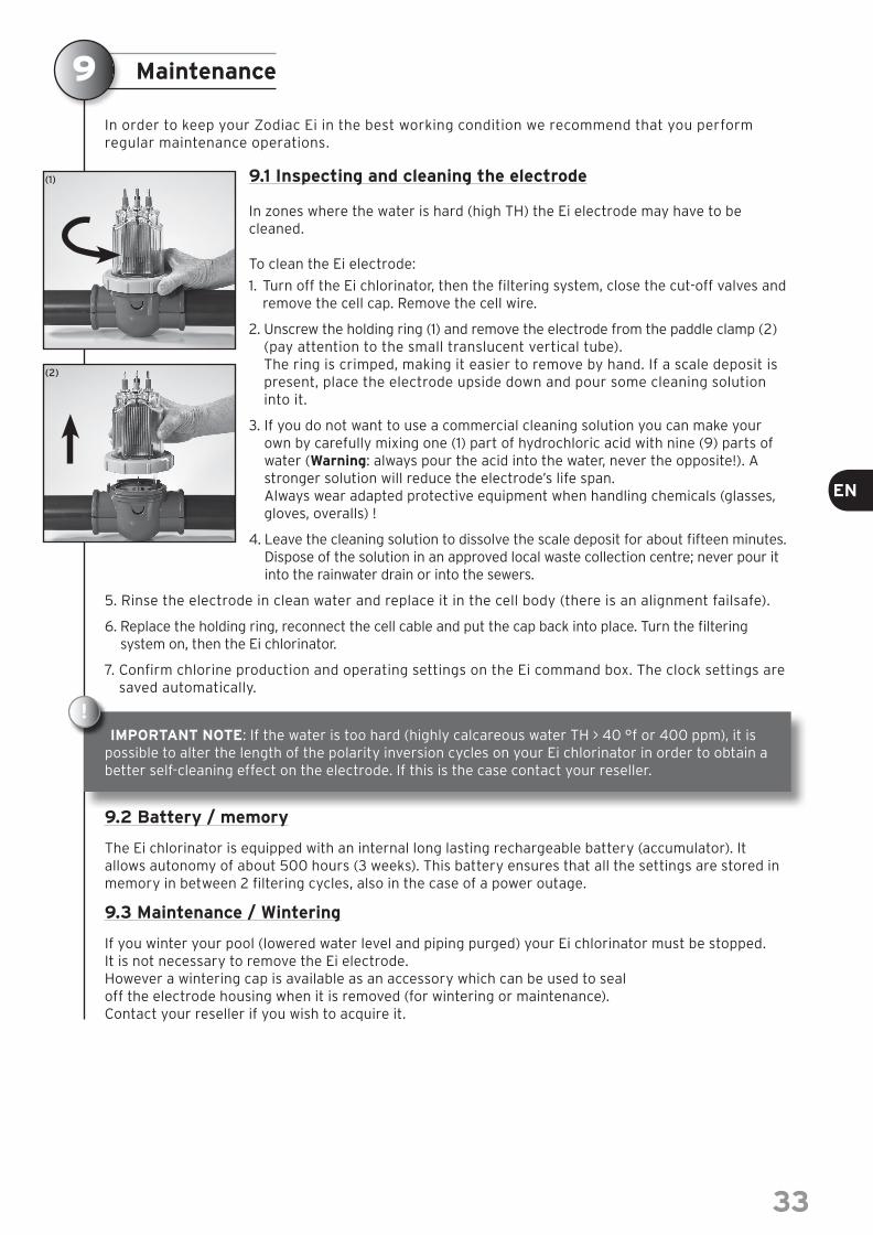
In order to keep your Zodiac Ei in the best working condition we recommend that you perform regular maintenance operations.
9.1 Inspecting and cleaning the electrode
In zones where the water is hard (high TH) the Ei electrode may have to be cleaned.
To clean the Ei electrode:
1. Turn off the Ei chlorinator, then the fi ltering system, close the cut-off valves and remove the cell cap. Remove the cell wire.
2. Unscrew the holding ring (1) and remove the electrode from the paddle clamp (2) (pay attention to the small translucent vertical tube).The ring is crimped, making it easier to remove by hand. If a scale deposit is present, place the electrode upside down and pour some cleaning solution into it.
3. If you do not want to use a commercial cleaning solution you can make your own by carefully mixing one (1) part of hydrochloric acid with nine (9) parts of water (Warning: always pour the acid into the water, never the opposite!). A stronger solution will reduce the electrode’s life span.Always wear adapted protective equipment when handling chemicals (glasses, gloves, overalls) !
4. Leave the cleaning solution to dissolve the scale deposit for about fi fteen minutes. Dispose of the solution in an approved local waste collection centre; never pour it into the rainwater drain or into the sewers.
5. Rinse the electrode in clean water and replace it in the cell body (there is an alignment failsafe).
6. Replace the holding ring, reconnect the cell cable and put the cap back into place. Turn the fi ltering system on, then the Ei chlorinator.
7. Confi rm chlorine production and operating settings on the Ei command box. The clock settings are saved automatically.
IMPORTANT NOTE: If the water is too hard (highly calcareous water TH > 40 °f or 400 ppm), it is possible to alter the length of the polarity inversion cycles on your Ei chlorinator in order to obtain a better self-cleaning effect on the electrode. If this is the case contact your reseller.
9.2 Battery / memory
The Ei chlorinator is equipped with an internal long lasting rechargeable battery (accumulator). It allows autonomy of about 500 hours (3 weeks). This battery ensures that all the settings are stored in memory in between 2 fi ltering cycles, also in the case of a power outage.
9.3 Maintenance / Wintering
If you winter your pool (lowered water level and piping purged) your Ei chlorinator must be stopped.It is not necessary to remove the Ei electrode.However a wintering cap is available as an accessory which can be used to seal off the electrode housing when it is removed (for wintering or maintenance). Contact your reseller if you wish to acquire it.
!
9
(1)
(2)
33
32
7.3 ‘OUTPUT FAULT’
Interpretation: There is a problem with the internal power supply to the Ei command box. Causes possibles :> Cell power supply cable disconnected or incorrectly connected.> Internal power problem in the command box following an external electrical incident. Solutions:
> Turn the Ei chlorinator off ( button) and cut off the power supply to the command box; then check that all the wires are correctly connected (mains, cell…).
> Contact your reseller.
7.4 ‘TEST CELL’
Interpretation:The electrode is dirty, scaled and/or worn. Causes possibles :Faulty fi ltering (pre-fi lter or diaphragm), water too hard (TH), electrode too old. This message will also de displayed after 9,000 hours of operation of the Ei cell, to have your retailer check the condition of the cell. Solutions: > Clean and/or check the fi ltering system (pump & fi lter).> Check the TH level and add calcium sequestering products if needed. Change the polarity inversion
cycle intervals if the TH > 40 °f or 400 ppm (see the important note in the Inspecting and cleaning the electrode paragraph).
> Replace the electrode with a new one.
7.5 «INVERSION»
Interpretation:The Ei chlorinator is inversing the cell polarity. This is an automatic self-cleaning cycle; the message does not indicate an error but is displayed for information purposes only. Solution :Wait for about 10 minutes and the chlorine production will resume automatically at the set levels.
Safety
> The installation and use of the Ei salt chlorinator requires full compliance with the recommendations of the present document For additional information, please contact your professional pool retailer.
> During any intervention on the pool’s hydraulic circuit and/or fi ltering system, remember to switch off
the Ei chlorinator fi rst ( button), then switch off the fi ltering unit and the mains power supply.
> During a fi lter backwash your Ei chlorinator MUST be turned off ( button).
> Do not scrape the electrodes with a brush or a metal object, do not bend them.
> The maximum acceptable water temperature for water in the Ei cell should not be in excess of 40 °C for optimal production.
> Water pressure in the Ei cell must not exceed 2.75 bar (275 kPa or 40 PSI).
> Check the Ei cell regularly to ensure there is no debris that the fi lter may not have stopped and/or that there is no scale deposit on the electrodes.
> The Ei power pack should not be installed above a heat source (pump, heating, radiator, closed block…). It must also be mounted on a vertical wall in a dry and well ventilated place.
> The life span of the Ei electronic equipment will be extended signifi cantly if it is protected from direct sunlight, from humidity and from all types of chemical products.
8
32
Maintenance
In order to keep your Zodiac Ei in the best working condition we recommend that you perform regular maintenance operations.
9.1 Inspecting and cleaning the electrode
In zones where the water is hard (high TH) the Ei electrode may have to be cleaned.
To clean the Ei electrode:
1. Turn off the Ei chlorinator, then the fi ltering system, close the cut-off valves and remove the cell cap. Remove the cell wire.
2. Unscrew the holding ring (1) and remove the electrode from the paddle clamp (2) (pay attention to the small translucent vertical tube).The ring is crimped, making it easier to remove by hand. If a scale deposit is present, place the electrode upside down and pour some cleaning solution into it.
3. If you do not want to use a commercial cleaning solution you can make your own by carefully mixing one (1) part of hydrochloric acid with nine (9) parts of water (Warning: always pour the acid into the water, never the opposite!). A stronger solution will reduce the electrode’s life span.Always wear adapted protective equipment when handling chemicals (glasses, gloves, overalls) !
4. Leave the cleaning solution to dissolve the scale deposit for about fi fteen minutes. Dispose of the solution in an approved local waste collection centre; never pour it into the rainwater drain or into the sewers.
5. Rinse the electrode in clean water and replace it in the cell body (there is an alignment failsafe).
6. Replace the holding ring, reconnect the cell cable and put the cap back into place. Turn the fi ltering system on, then the Ei chlorinator.
7. Confi rm chlorine production and operating settings on the Ei command box. The clock settings are saved automatically.
IMPORTANT NOTE: If the water is too hard (highly calcareous water TH > 40 °f or 400 ppm), it is possible to alter the length of the polarity inversion cycles on your Ei chlorinator in order to obtain a better self-cleaning effect on the electrode. If this is the case contact your reseller.
9.2 Battery / memory
The Ei chlorinator is equipped with an internal long lasting rechargeable battery (accumulator). It allows autonomy of about 500 hours (3 weeks). This battery ensures that all the settings are stored in memory in between 2 fi ltering cycles, also in the case of a power outage.
9.3 Maintenance / Wintering
If you winter your pool (lowered water level and piping purged) your Ei chlorinator must be stopped.It is not necessary to remove the Ei electrode.However a wintering cap is available as an accessory which can be used to seal off the electrode housing when it is removed (for wintering or maintenance). Contact your reseller if you wish to acquire it.
!
9
(1)
(2)
33
33
EN

Warranty
Mise au rebut du produit - Protection de l’environnement :
Conformément aux exigences de la directive DEEE - 2002/96/CE (Déchets d’Équipements
Électriques et Électroniques), les produits électriques et électroniques usagés doivent être détruits séparément des ordures ménagères normales afi n de promouvoir la réutilisation, le recyclage et d’autres formes de récupération, ainsi que de limiter
la quantité de déchets devant être éliminés et de réduire du même coup les décharges.
Lorsque vous vous débarrasserez de ce produit, respectez les prescriptions locales pour l’élimination des déchets. Ne le jetez pas dans la nature, mais remettez- le à un centre de collecte spécialisé de rebuts électriques et électroniques et/ou renseignez-vous auprès de votre revendeur lors de l’achat d’un nouveau produit.
10
!
PrincipleUnless otherwise stipulated, we contractually guarantee the correct op-eration of our new Products. We guarantee that our Products conform to their technical specifi cations and that they are free of material and manufacturing default.The present warranty is limited, at our discretion, either to the repair or exchange for a new or repacked Product, or to the refund of any Products recognized as being defective by our services. Shipping expenses for the repaired or replaced Products delivered to the client will be borne by us, excluding any labour costs, travel and/or accommodation expenses in-curred as the result of repairs made outside of continental France and excluding any payment of damages. All Product returns must fi rst be approved and decided by our services. Returns sent by the Client without our prior approval will not be accepted.In particular, the spare parts warranty will only be honoured after analy-sis and expertise of the returned spare parts by our company followed by the decision to replace said parts.In all cases the seller’s legal warranty will continue to apply.In order to benefi t from the warranty, the Client and the End User agree to respect the following parameters concerning the balance of the swim-ming pool water: - pH: 6.8 < pH < 7.6- free chlorine (* : < 3,0 mg/L- total bromine (*): < 5.0 mg/L- stabilising agent (if used): < 75 mg/L- total dissolved metals (iron, manganese, copper, zinc…) : < 0.1 mg/L(*): Cleaning robots must absolutely be removed from the pool before using a shock treatment.Note: Using water drawn from a well is forbidden.
General limitationsThe present warranty does not apply to visible defects that the Client failed to report upon accepting delivery of the Products.Also excluded from the warranty are: defects or deterioration due to the unsuitability of the Product with respect to the end User’s needs, due to normal wear, to negligence, to incorrect installation or to a use that does not conform to the recommendations mentioned in the User Manual, to lack of maintenance and/or a handling accident, to in-correct storage, and/or by studies, instructions and/or specifi cations made by our Client.Any modifi cations made by the Client, by the End User or by any third party to our Products will automatically void the warranty in full. The same will apply if original parts were to be replaced with spare parts not sold by us.
Our Client will be responsible for ensuring compatibility of our Prod-ucts with any other pool equipment it may be installed with, by check-ing with the different manufacturers concerned, also for ensuring that all installation and operating instructions and rules are respected in order for the overall system to operate correctly.In the case of a return of the product to our workshop, shipping ex-penses to and fro, will be borne by the end user, except for those ex-penses mentioned under paragraph 2 of the present article.Immobilisation and deprivation of use of an appliance due to repair will not give the right to compensation. This warranty will become void in the case of a default in payment or late payment by our Client for the Product concerned.
Period covered by the warrantyThe effective warranty start date is the date mentioned on the sales invoice for the new Product as issued by our Client to the End User. This document will be required as proof of purchase in order for the warranty to come into play. Failing this, our Client shall bear the full cost of any claims made by the end User under the contractual war-ranty and after its expiry date.Under no circumstances shall any repairs or replacements carried out under the terms of this warranty cause its duration to be extended or renewed.
Particular dispositions for Products of the Salt chlorinator and Regulation rangeThe range of salt chlorinators benefi ts from a total and unconditional warranty: regardless of the cause of deterioration, the control unit and the cell will be repaired or exchanged during the period covered by the warranty.The warranty is valid for a period of 2 years starting from the date mentioned on the invoice for the new Product, as issued by our Client to the end User.For the TRi range, the warranty is extended to 3 years (excluding op-tional modules «TRi pH» and «TRi PRO»).For all products the warranty will only be considered to be valid under the condition that installation is performed by a qualifi ed profession-al, except for products in the Ei salt chlorinators range.Note : This unconditional warranty does not apply to our range of regu-lation products (pH Perfect, TRi pH and TRi PRO modules).
Register your product on our website:- You will be the fi rst to be informed of new Zodiac products and special offers.
- You can help us to constantly improve our product quality.
www.zodiac-poolcare.com
For any warranty issue, please contact your local dealer.We recommend that you keep your purchase invoice carefully if you requireassistance for your product.
34
Le agradecemos que haya elegido el clorador salino Ei para el mantenimiento de su piscina.
A partir de ahora, su piscina sólo será una fuente de relajación y de bienestar, dado que el Ei le ahorra muchas de las operaciones de tratamiento manual y le ofrece un agua sana, cristalina y más natural durante toda la temporada.
Le recomendamos que lea detenidamente estas instrucciones antes de la instalación y el uso del clorador salino Ei.
Índice
Contenido del embalaje página 36
Recomendaciones página 37
Guía de instalación y de uso página 383.1 Emplazamiento de la unidad de mando Ei ................................................................................................................................................................................ 383.2 Instalación de la célula Ei ..........................................................................................................................................................................................................................393.3 Instalación del detector de caudal ..................................................................................................................................................................................................403.4 Conexión de la unidad de mando Ei .................................................................................................................................................................................................41
Confi guración del clorador salino Ei página 414.1 Descripción del panel de control Ei ....................................................................................................................................................................................................414.2 Elección del idioma .........................................................................................................................................................................................................................................424.3 Ajuste del reloj (CLOCK) ............................................................................................................................................................................................................................424.4 Ajuste del programador (TIMER) ......................................................................................................................................................................................................434.5 Puesta en marcha manual .......................................................................................................................................................................................................................444.6 Uso de un reloj externo (unidad de mando de la fi ltración) ..................................................................................................................................444.7 Ajuste de la producción de cloro .......................................................................................................................................................................................................44
Conexión a un controlador externo (domótica) página 455.1 Confi gurar el tipo de controlador .......................................................................................................................................................................................................455.2 Precauciones durante el cableado de un controlador ................................................................................................................................................455.4 Comprobación del cableado y de las conexiones ............................................................................................................................................................46
Parámetros del equilibrio del agua página 47
Mensajes de error y avisos: signifi cado página 477.1 “CONTROLAR SAL” .......................................................................................................................................................................................................................................... 477.2 “FALLO CAUDAL” .............................................................................................................................................................................................................................................. 477.3 “FALLO PROD.” ....................................................................................................................................................................................................................................................487.4 “REVISAR CELULA” ........................................................................................................................................................................................................................................487.5 “INVERSIÓN” .........................................................................................................................................................................................................................................................48
Seguridad de uso página 48
Mantenimiento página 499.1 Inspección y limpieza del electrodo ................................................................................................................................................................................................. 499.2 Batería / memoria ............................................................................................................................................................................................................................................ 499.3 Mantenimiento / Hibernación: ............................................................................................................................................................................................................. 49
Garantía página 50
1
2
3
4
5
6
7
8
9
10
35
34
www.zodiac-poolcare.com
Pour plus de renseignements, merci de contacter votre revendeurFor further information please contact your retailerPara cualquier información adicional contactar con su detallistaHinweise und Auskünfte erhalten Sie bei Ihrem HändlerPer qualsiasi informazione supplementare, mettetevi in contattocon il vostro rivenditore al dettaglio Contacte o seu revendador para obter informaçoes mais detalhadasVoor nadere inlichtingen kunt u zich wenden tot uw zwembadbouwer
Zodiac : Innovative pool products and services
Your retailer/ votre revendeur
Product name plate - Plaque signalétique
PRODUCT NAME PLATE - PLAQUE SIGNALÉTIQUE
ZO
DIA
C P
OO
L C
AR
E E
UR
OP
E /
BP
90
02
3, 4
918
0 S
t B
arth
élém
y d
’An
jou
ced
ex-F
ran
ce /
S.A
.S.U
AU
CA
PIT
AL
DE
517
20
0 E
/ S
IRE
N 3
95
06
8 6
79
/ R
CS
PA
RIS
/ P
ou
r Q
ui P
ou
rqu
oi /
Ed
itio
n 11
-20
10 /
W17
69
61-
1