Embed Size (px)
Citation preview
Instructions 95-8472Combustible Gas DetectorTransmitter Model 505 withCombustible Gas Sensor Model CGS
3.1 Rev: 4/12 95-8472
Table Of Contents
SAFETY MESSAGES . . . . . . . . . . . . . . . . . . . . . . . . . . . . . . . . . . . . . . . .i
Section I - Description and Operating Characteristics
DESCRIPTION . . . . . . . . . . . . . . . . . . . . . . . . . . . . . . . . . . . . . . . . . . . . 1Sensor . . . . . . . . . . . . . . . . . . . . . . . . . . . . . . . . . . . . . . . . . . . . . . . . 1
GENERAL APPLICATION INFORMATION . . . . . . . . . . . . . . . . . . . . . . . 1
SENSOR RESPONSE . . . . . . . . . . . . . . . . . . . . . . . . . . . . . . . . . . . . . . 2
FACTORS AFFECTING SENSOR SENSITIVITY . . . . . . . . . . . . . . . . . . 2
SPECIFICATIONS . . . . . . . . . . . . . . . . . . . . . . . . . . . . . . . . . . . . . . . . . . 4Transmitter . . . . . . . . . . . . . . . . . . . . . . . . . . . . . . . . . . . . . . . . . . . . 4Catalytic Sensor . . . . . . . . . . . . . . . . . . . . . . . . . . . . . . . . . . . . . . . . 5
Section II - Installation and Startup
INSTALLATION . . . . . . . . . . . . . . . . . . . . . . . . . . . . . . . . . . . . . . . . . . . . . 6Sensor Location . . . . . . . . . . . . . . . . . . . . . . . . . . . . . . . . . . . . . . . . . 6Wiring Requirements . . . . . . . . . . . . . . . . . . . . . . . . . . . . . . . . . . . . . 6Model 505 Wiring . . . . . . . . . . . . . . . . . . . . . . . . . . . . . . . . . . . . . . . . 7Sensor Separation . . . . . . . . . . . . . . . . . . . . . . . . . . . . . . . . . . . . . . . 7Sensor Voltage Adjustment . . . . . . . . . . . . . . . . . . . . . . . . . . . . . . . . . 8Replacing an Existing K Series or Model 500 Transmitter with a . . . .
Model 505 . . . . . . . . . . . . . . . . . . . . . . . . . . . . . . . . . . . . . . . . . . 9
STARTUP PROCEDURE . . . . . . . . . . . . . . . . . . . . . . . . . . . . . . . . . . . . . 9
CALIBRATION . . . . . . . . . . . . . . . . . . . . . . . . . . . . . . . . . . . . . . . . . . . . 10Calibration Procedure . . . . . . . . . . . . . . . . . . . . . . . . . . . . . . . . . . . . 10Calibration using K-Factors . . . . . . . . . . . . . . . . . . . . . . . . . . . . . . . . 10
Section III - System Maintenance
TROUBLESHOOTING . . . . . . . . . . . . . . . . . . . . . . . . . . . . . . . . . . . . . . 12
ROUTINE MAINTENANCE . . . . . . . . . . . . . . . . . . . . . . . . . . . . . . . . . . . 12Checkout in Normal Mode . . . . . . . . . . . . . . . . . . . . . . . . . . . . . . . . . 12Sensor Inspection . . . . . . . . . . . . . . . . . . . . . . . . . . . . . . . . . . . . . . . 12Sensor Sensitivity . . . . . . . . . . . . . . . . . . . . . . . . . . . . . . . . . . . . . . . 12Sensor Replacement . . . . . . . . . . . . . . . . . . . . . . . . . . . . . . . . . . . . 12
REPLACEMENT PARTS . . . . . . . . . . . . . . . . . . . . . . . . . . . . . . . . . . . . . 13
DEVICE REPAIR AND RETURN . . . . . . . . . . . . . . . . . . . . . . . . . . . . . . . 13
ORDERING INFORMATION . . . . . . . . . . . . . . . . . . . . . . . . . . . . . . . . . . 14
Appendices
APPENDIX A – FM APPROVAL . . . . . . . . . . . . . . . . . . . . . . . . . . . . . . 15
APPENDIX B – CSA APPROVAL . . . . . . . . . . . . . . . . . . . . . . . . . . . . . 16
APPENDIX C – ATEX / CE APPROVAL . . . . . . . . . . . . . . . . . . . . . . . . 17
APPENDIX D – IECEx APPROVAL . . . . . . . . . . . . . . . . . . . . . . . . . . . . 19
IMPORTANTBe sure to read and understand the entire instruction manual before installing, operating or servicing the gas detection equipment.
WARNINGDo not open the transmitter enclosure with power applied unless it is verified that no combustible gases or vapors are present. A portable gas detection instrument should be used to ensure that the area is clear of any combustible gases. Calibration or maintenance should not be performed if there is any indication of the presence of combustible gas at the sensor.
WARNINGIt is possible for the transmitter output to drop to a low LFL level after going into high alarm and still have a dangerous level of combustible gas present. Therefore, precautions should be taken to ensure that the combustible gas has been cleared before considering the area safe.
WARNINGThe sintered metal flame arrestor is an integral part of the combustible gas sensor. DO NOT operate the gas detector if the flame arrestor is damaged or missing, since the exposed element is a potential ignition source.
CAUTIONTo ease installation and future removal, ensure that all junction box covers and sensor threads are properly lubricated. If the need arises for additional lubrication, use either Lubriplate grease (P/N 102868-001) or Teflon tape for sensor threads. Avoid the use of silicone grease.
CAUTIONThe wiring instructions in this manual will provide safe and proper functioning of the device under normal conditions. However, local variations in wiring codes and regulations exist, and total compliance with these ordinances cannot be guaranteed. Be certain that all wiring complies with the IEC/NEC as well as all local ordinances. If in doubt, consult the local authority having jurisdiction before wiring the system.
NOTEThroughout this manual, the device receiving the output signal from the transmitter will be referred to as the “controller.” A typical controller provides a visual display of the % LFL output from the monitored transmitter, indicators for alarm and trouble conditions, and outputs for controlling response devices. Other control systems are also compatible with the Model 505.
Safety Messages
i

Section I — Description and
Operating Characteristics
DESCRIPTION
The Model 505 Transmitter is used with one constant voltage catalytic gas sensor to provide a linear 4 to 20 mA output signal corresponding to a 0 to 100% LFL gas concentration (see Figure 1). Intrusive calibration and sensor sensitivity checks are performed using a standard digital voltmeter (not provided). An explosion-proof junction box with removable cover is included with all Model 505 Transmitters. Options include junction box material (aluminum or stainless steel), number of conduit entry ports (up to five), conduit entry threads (NPT or Metric), orientation of entries (180 degree straight-through or 90 degree “L”), and signal output load impedance (125 or 500 ohms). Detector Electronics Corporation’s (Det-tronics®) Model 505 with signal loop impedance option “A” directly replaces the K-Series Transmitter (125 ohms), and the Model 505 with signal loop impedance option “B” replaces the Model 500 Transmitter (500 ohms).
SENSOR
Det-Tronics constant voltage catalytic bead type combustible gas sensors are used with the Model 505 transmitter family.
GENERAL APPLICATION INFORMATION
A combustible vapor or gas is one that will burn when mixed with air (or oxygen) and ignited. Every vapor has a minimum and maximum concentration in air, which together form the “flammable” or “explosive” range. The lower flammable limit (LFL) is defined as the smallest amount of the gas that will support a self-propagating flame when mixed with air (or oxygen) and ignited. The range of gas concentration measurement for most catalytic sensor-based gas detection systems, including the Model 505 transmitter, is 0 to 100% LFL, with 0% LFL
being a gas-free atmosphere and 100% LFL equaling the gas concentration at its lower flammable limit. The relationship between % LFL and % by volume differs from gas to gas. ASTM E681 is the existing standard method for determining flammable limits. Examples include:
Hydrogen (H2), 100% LFL = 4.0% by volume in air
Methane (CH4), 100% LFL = 5.0% by volume in air
Ethane (C2H6), 100% LFL = 3.0% by volume in air
Ethylene (C2H4), 100% LFL = 2.7% by volume in air
Pentane (C5H12), 100% LFL = 1.5% by volume in air
Propane (C3H8), 100% LFL = 2.2% by volume in air
For data on other gases, refer to NFPA Handbook 325M.
Typical alarm setpoints for combustible gas detection systems are 20% LFL for the low alarm and 40% LFL for the high alarm.
The LFL of a gas is affected by temperature and pressure. As the temperature increases, the LFL concentration decreases, and the explosion hazard increases. The relationship between LFL and pressure is fairly complex, however, a pressure increase usually lowers the LFL. The LFL of a gas is not significantly affected by the humidity fluctuations normally encountered in typical industrial applications.
INSTRUCTIONS
Combustible Gas Detector
Transmitter Model 505 with
Combustible Gas Sensor Model CGS
3.1 ©Detector Electronics Corporation 2012 Rev: 4/12 95-8472
2 95-84723.1
SENSOR RESPONSE
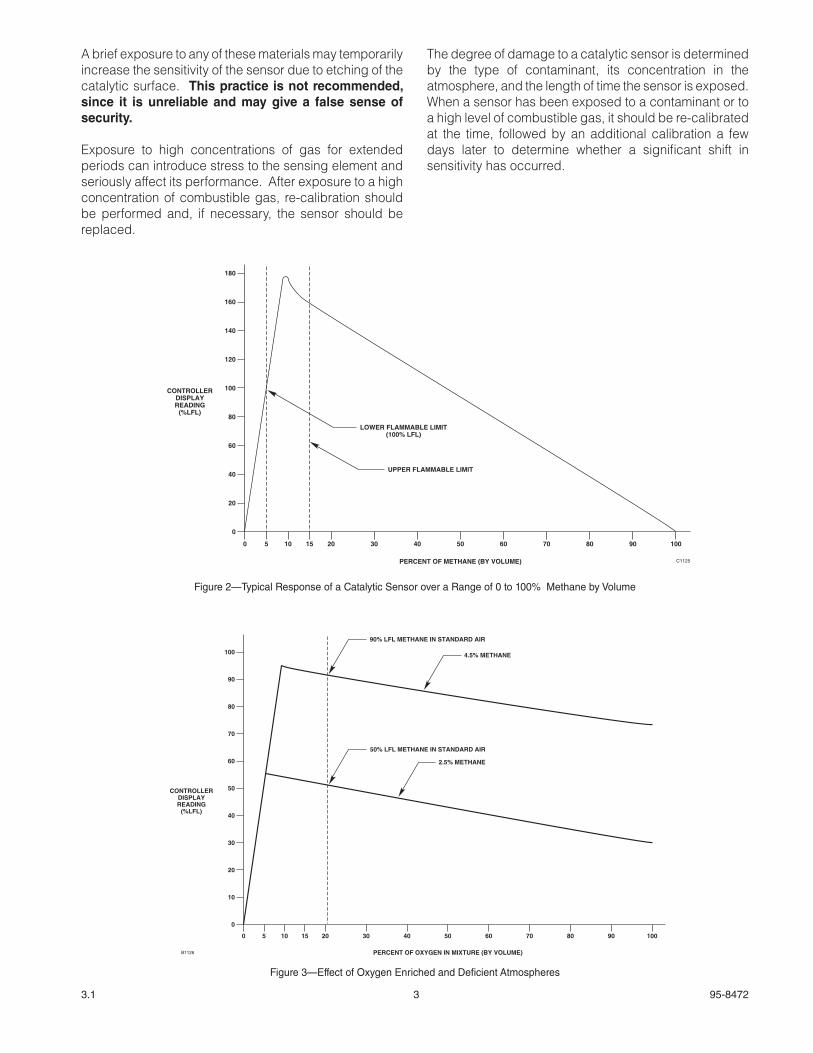
Figure 2 shows the typical response of a catalytic gas sensor to various levels of methane. Note that a reading of 40% LFL will be given at 2.0% by volume methane and also at 80.0% by volume methane, which is well above the upper flammable limit. Although gas concentrations above the upper flammable limit will not propagate a flame, it is likely that somewhere in the protected area there may be a flammable concentration.
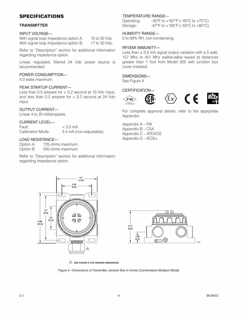
All catalytic sensors require oxygen to accurately measure combustible gas concentrations. Sensor response and accuracy will decrease when the oxygen level is less than 10%. Figure 3 shows the effect of oxygen enriched and oxygen deficient atmospheres on the response of a typical catalytic gas sensor. Do not use catalytic gas sensors in areas where the oxygen level is less than 10% by volume.
FACTORS AFFECTING SENSOR SENSITIVITY
There are a variety of factors that can cause a decrease in the sensitivity of catalytic type combustible gas sensors. The following information identifies the most common substances that can have a detrimental effect on the catalytic gas sensor. Under no circumstances should these lists be considered as all inclusive.
Interfering or contaminating substances include materials that can clog the pores of the sintered steel flame arrestor and reduce the gas diffusion rate to the sensor. Examples include:
1. Dirt or oil.
A dust cover or splash guard should be installed to protect the flame arrestor. The dust cover may be cleaned using an organic solvent and an ultrasonic bath unless the contaminant is insoluble. Replace dust cover if there is any doubt.
2. Corrosive liquids and vapors.
This can occur when substances such as H2S, (hydrogen sulfide), Cl2 (chlorine) or HCl (hydrochloric acid) are present. A dust cover may provide some limited protection. Routine calibration frequency should be increased in applications where corrosive materials are present.
3. Flame arrestor clogged as a result of painting or cleaning.
The routine maintenance procedure should include first powering down the system, then covering the sensor with a plastic bag when painting or cleaning. The bag should be removed as soon as possible when the procedure is complete. Recalibrate the sensors after re-powering and stabilization.
4. Polymer formation in the flame arrestor.
This can occur where monomeric vapors such as 1-3 butadiene, styrene, isoprene, etc. are present. This may render the sensor dead.
Some substances can cover or tie up the active sites on the catalytic surface of the active sensing element. This occurs in the presence of volatile metal organics, gases, hydride vapors, and volatile compounds containing phosphorous, boron, silicon, etc.
Examples: Tetraethyl lead Phosphine Diborane Silane Trimethyl chlorsilane Hydrogen fluoride Boron trifluoride Phosphate esters Silicone oils and greases RTV silicone sealants
Some substances react with the catalytic element metal, forming a volatile compound. This erodes the metal from the surface. With sufficient exposure, most or all of the metal catalyst can be removed from the surface of the active element of the sensor. Halogens and compounds that contain halogens are materials of this nature.
Examples: Chlorine Bromine Iodine Hydrogen Chloride, Bromide or Iodide Organic halides Trichloroethylene Dichlorobenzene Vinyl chloride Freons Halon 1301 (Bromotrifluoromethane)
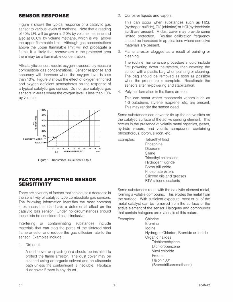
0 2 4 6 8 10 12 14 16 18 20
100%
80%
60%
40%
20%
0%
MILLIAMPERES DC A1945
CALIBRATE MODE
LF
LP
ER
CE
NT
AG
E
3.4
FAULT
Figure 1—Transmitter DC Current Output
3 95-84723.1
A brief exposure to any of these materials may temporarily increase the sensitivity of the sensor due to etching of the catalytic surface. This practice is not recommended, since it is unreliable and may give a false sense of security.
Exposure to high concentrations of gas for extended periods can introduce stress to the sensing element and seriously affect its performance. After exposure to a high concentration of combustible gas, re-calibration should be performed and, if necessary, the sensor should be replaced.
The degree of damage to a catalytic sensor is determined by the type of contaminant, its concentration in the atmosphere, and the length of time the sensor is exposed. When a sensor has been exposed to a contaminant or to a high level of combustible gas, it should be re-calibrated at the time, followed by an additional calibration a few days later to determine whether a significant shift in sensitivity has occurred.
0 905 10 15 20 30 40 50 60 70 80 100
180
160
140
120
100
80
60
40
20
0
CONTROLLERDISPLAYREADING
(%LFL)
PERCENT OF METHANE (BY VOLUME)
LOWER FLAMMABLE LIMIT(100% LFL)
UPPER FLAMMABLE LIMIT
C1125
Figure 2—Typical Response of a Catalytic Sensor over a Range of 0 to 100% Methane by Volume
0 905 10 15 20 30 40 50 60 70 80 100
100
90
80
70
60
50
40
30
20
10
0
CONTROLLERDISPLAYREADING
(%LFL)
PERCENT OF OXYGEN IN MIXTURE (BY VOLUME)B1126
50% LFL METHANE IN STANDARD AIR
4.5% METHANE
2.5% METHANE
90% LFL METHANE IN STANDARD AIR
Figure 3—Effect of Oxygen Enriched and Deficient Atmospheres
4 95-84723.1
SPECIFICATIONS
TRANSMITTER
INPUT VOLTAGE—With signal loop impedance option A: 10 to 30 VdcWith signal loop impedance option B: 17 to 30 Vdc.
Refer to “Description” section for additional information regarding impedance option.
Linear, regulated, filtered 24 Vdc power source is recommended.
POWER CONSUMPTION—4.0 watts maximum.
PEAK STARTUP CURRENT—Less than 0.5 ampere for < 0.2 second at 10 Vdc input, and less than 0.2 ampere for < 0.2 second at 24 Vdc input.
OUTPUT CURRENT—Linear 4 to 20 milliamperes.
CURRENT LEVEL—Fault: < 2.0 mA.Calibration Mode: 3.4 mA (non-adjustable).
LOAD RESISTANCE—Option A: 125 ohms maximum.Option B: 500 ohms maximum.
Refer to “Description” section for additional information regarding impedance option.
TEMPERATURE RANGE—Operating: –40°F to +167°F (–40°C to +75°C).Storage: –67°F to +185°F (–55°C to +85°C).
HUMIDITY RANGE—0 to 99% RH, non-condensing.
RFI/EMI IMMUNITY—Less than ± 0.5 mA signal output variation with a 5 watt, 157 Mhz or 451 Mhz walkie-talkie keyed at distances greater than 1 foot from Model 505 with junction box cover installed.
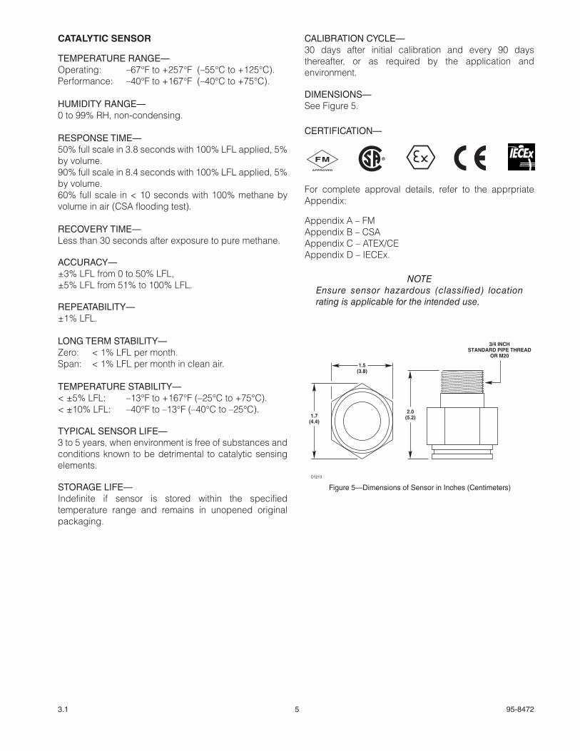
DIMENSIONS—See Figure 4.
CERTIFICATION—
For complete approval details, refer to the apprpriate Appendix:
Appendix A – FMAppendix B – CSAAppendix C – ATEX/CEAppendix D – IECEx.
3.77(9.6)
1.28(3.3)
3.46(8.8)
4.7(11.9)
2.7(6.9)
5.2(13.2)5.86
(14.9)
E2281
1
1 SEE FIGURE 5 FOR SENSOR DIMENSIONS
Figure 4—Dimensions of Transmitter Junction Box in Inches (Centimeters) Multiport Model
FMAPPROVED
®FMAPPROVED
®FMAPPROVED
®
5 95-84723.1
CATALYTIC SENSOR
TEMPERATURE RANGE—Operating: –67°F to +257°F (–55°C to +125°C).Performance: –40°F to +167°F (–40°C to +75°C).
HUMIDITY RANGE—0 to 99% RH, non-condensing.
RESPONSE TIME—50% full scale in 3.8 seconds with 100% LFL applied, 5% by volume.90% full scale in 8.4 seconds with 100% LFL applied, 5% by volume.60% full scale in < 10 seconds with 100% methane by volume in air (CSA flooding test).
RECOVERY TIME—Less than 30 seconds after exposure to pure methane.
ACCURACY—±3% LFL from 0 to 50% LFL,±5% LFL from 51% to 100% LFL.
REPEATABILITY—±1% LFL.
LONG TERM STABILITY—Zero: < 1% LFL per month.Span: < 1% LFL per month in clean air.
TEMPERATURE STABILITY—< ±5% LFL: –13°F to +167°F (–25°C to +75°C).< ±10% LFL: –40°F to –13°F (–40°C to –25°C).
TYPICAL SENSOR LIFE—3 to 5 years, when environment is free of substances and conditions known to be detrimental to catalytic sensing elements.
STORAGE LIFE—Indefinite if sensor is stored within the specified temperature range and remains in unopened original packaging.
CALIBRATION CYCLE—30 days after initial calibration and every 90 days thereafter, or as required by the application and environment.
DIMENSIONS—See Figure 5.
CERTIFICATION—
For complete approval details, refer to the apprpriate Appendix:
Appendix A – FMAppendix B – CSAAppendix C – ATEX/CEAppendix D – IECEx.
NOTEEnsure sensor hazardous (classified) location rating is applicable for the intended use.
2.0(5.2)
1.5(3.8)
1.7(4.4)
3/4 INCHSTANDARD PIPE THREAD
OR M20
D1213
Figure 5—Dimensions of Sensor in Inches (Centimeters)
FMAPPROVED
®FMAPPROVED
®FMAPPROVED
®
6 95-84723.1
Section II — Installation and Startup
INSTALLATION
CAUTIONAlways store and transport the sensor in the original factory packaging to ensure proper protection against contamination.
SENSOR LOCATION
Proper sensor positioning is essential to ensure maximum gas detection capability. Optimum sensor placement and density varies depending upon the conditions at the job site. The system designer and installer must examine the specific area to be protected and identify the most likely leak sources and gas accumulation areas to determine the best sensor locations.
The following factors should be considered for every installation:
1. What kind of gas is to be detected? If it is lighter than air (Acetylene, Hydrogen, Methane, etc.), place the sensor above the potential gas leak. Place it close to the floor for gases that are heavier than air (Benzene, Butane, Butylene, Propane, Hexane, Pentane, etc.) or for vapors resulting from flammable liquid spills. Careful analysis of both the vapor hazard and the application is required — first to determine the feasibility of detection and then to ensure that proper sensor locations are selected.
2. How rapidly will the gas diffuse into the air? Locate the sensor as close as practical to the anticipated source of a gas leak.
3. Ventilation characteristics of the immediate area must also be considered. Air movement can cause the gas to accumulate more heavily in one area than another. Smoke generator tests are useful in identifying typical air current patterns as well as “dead” air spots for both indoor and outdoor applications. The sensors should be placed where the most concentrated accumulation of gas is anticipated.
4. The sensor should be located in an area where it is safe from potential sources of contamination that could poison the sensing element.
5. The sensor should be pointed down to prevent the buildup of contaminants on the gas inlet.
6. The sensor must be accessible for testing and calibration.
7. Exposure to excessive heat or vibration can result in premature failure of electronic devices and should be avoided if possible. Shielding the transmitter from intense sunlight will reduce solar heating and enhance the service life of the unit.
IMPORTANTAll diffusion-based gas sensors including the catalytic gas sensor used with the Model 505 must contact the target gas in order to provide an accurate gas measurement and response. This must always be remembered when selecting locations for gas sensor installation.
WIRING REQUIREMENTS
Wire Size and Type
The transmitter is typically connected to the controller/power source using a three conductor shielded cable. Shielded cable is highly recommended to protect against interference caused by EMI and RFI. Cable shields should be connected to earth ground at the transmitter end only for maximum noise immunity. Shield termination to ground at the controller end only is also acceptable, but may offer reduced noise immunity.
The maximum allowable distance between the Model 505 and the output signal receiver (controller) is determined by the wire size used. For the Model 505 with signal loop impedance option “A,” the maximum loop resistance is 125 ohms. For the Model 505 with signal loop impedance option “B,” the maximum loop resistance is 500 ohms. Calculate the total linear distance and overall resistance of the signal cable. Do not exceed the maximum loop resistance for the Model 505 version being installed.
Power cable size must be adequate to ensure that no less than the minimum operating voltage is delivered to the transmitter under all operating conditions. Minimum operating voltage for the Model 505 with signal loop impedance option “A” is 10 Vdc, for the Model 505 with signal loop impedance option “B” it is 17 Vdc. A linear, filtered and regulated 24 Vdc power supply is recommended. Maximum wire size accepted by the Model 505 wire terminals is 12 AWG (2.5 mm2). It is acceptable to power the Model 505 from a 24 Vdc power source that is remotely located from the output signal receiver.
In applications where the wiring cable is installed in conduit, the conduit should not be used for wiring to other electrical equipment.
7 95-84723.1
Conduit Seals, Drains, and Breathers
The Model 505 Transmitter is designed and approved for use in hazardous areas where explosion-proof equipment certification is required. When installing the Model 505 in such areas, explosion-proof conduit seals should be installed within 18 inches (46 cm) of the transmitter housing. Conduit seals prevent the passage of vapors or flames through the conduit. Seals are recommended even if they are not required by local wiring codes.
Conduit systems are never completely air-tight. As a result, significant amounts of condensation can form within the conduit system. Therefore, it is important to take proper precautions during installation to ensure that moisture will not cause damage to the transmitter or other components of the system.
Conduit raceways should be inclined so that water will flow to low points for drainage and will not collect on conduit seals or inside enclosures. If this is not possible, install conduit drains above the seals to prevent the collection of water, or install a drain loop below the detector with a conduit drain at the lowest point of the loop.
Conduit drains should be installed at water collection points to automatically drain accumulated moisture. Conduit breathers should be installed at upper locations to provide ventilation and allow water vapor to escape. At least one breather should be used with each drain.
When using steel wire armored or mineral-insulated copper-sheathed cable, select an approved gland with a watertight compression stage and an overall gland shroud for outdoor applications. A sealing washer must be fitted between the gland and the conduit/cable entry to ensure IP66 rating.
MODEL 505 WIRING
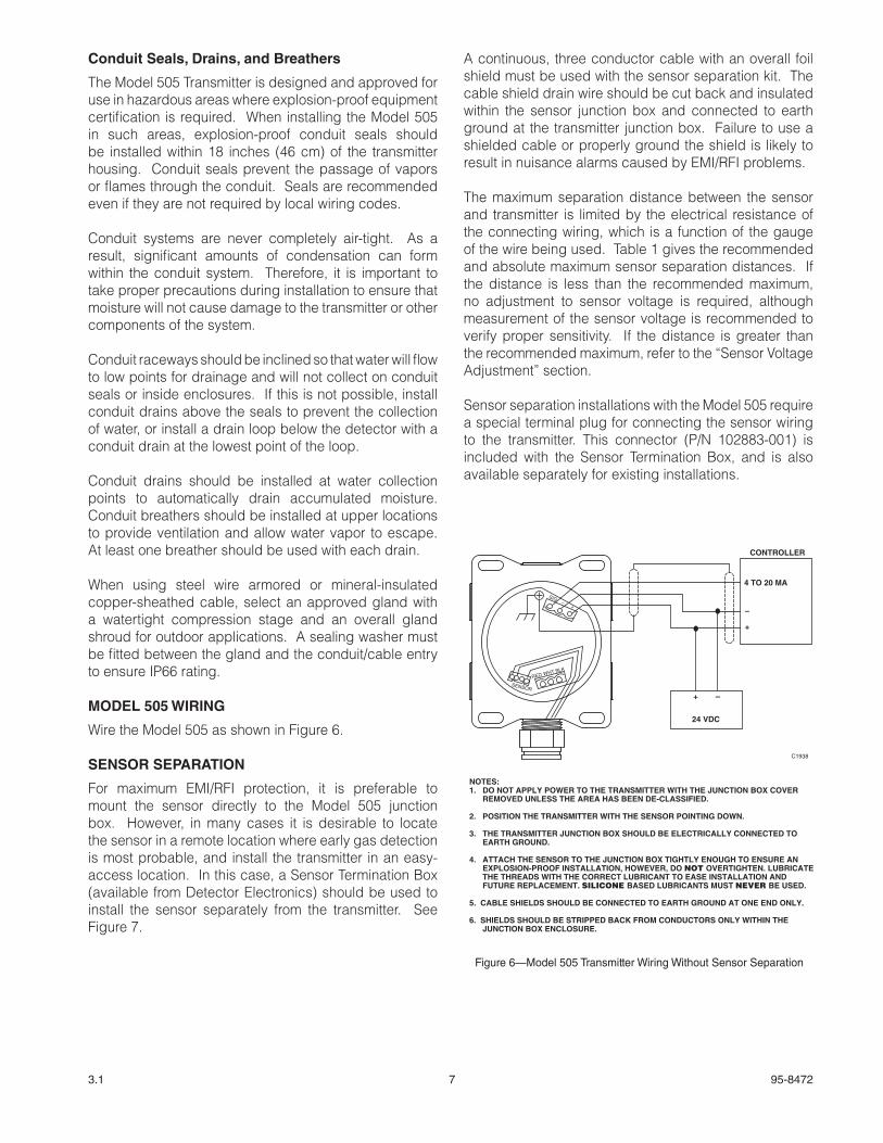
Wire the Model 505 as shown in Figure 6.
SENSOR SEPARATION
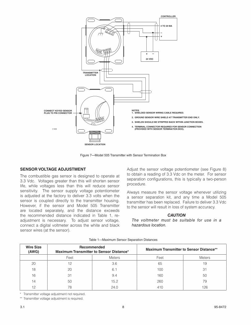
For maximum EMI/RFI protection, it is preferable to mount the sensor directly to the Model 505 junction box. However, in many cases it is desirable to locate the sensor in a remote location where early gas detection is most probable, and install the transmitter in an easy-access location. In this case, a Sensor Termination Box (available from Detector Electronics) should be used to install the sensor separately from the transmitter. See Figure 7.
A continuous, three conductor cable with an overall foil shield must be used with the sensor separation kit. The cable shield drain wire should be cut back and insulated within the sensor junction box and connected to earth ground at the transmitter junction box. Failure to use a shielded cable or properly ground the shield is likely to result in nuisance alarms caused by EMI/RFI problems.
The maximum separation distance between the sensor and transmitter is limited by the electrical resistance of the connecting wiring, which is a function of the gauge of the wire being used. Table 1 gives the recommended and absolute maximum sensor separation distances. If the distance is less than the recommended maximum, no adjustment to sensor voltage is required, although measurement of the sensor voltage is recommended to verify proper sensitivity. If the distance is greater than the recommended maximum, refer to the “Sensor Voltage Adjustment” section.
Sensor separation installations with the Model 505 require a special terminal plug for connecting the sensor wiring to the transmitter. This connector (P/N 102883-001) is included with the Sensor Termination Box, and is also available separately for existing installations.
NOTES:1. DO NOT APPLY POWER TO THE TRANSMITTER WITH THE JUNCTION BOX COVER
REMOVED UNLESS THE AREA HAS BEEN DE-CLASSIFIED.
2. POSITION THE TRANSMITTER WITH THE SENSOR POINTING DOWN.
3. THE TRANSMITTER JUNCTION BOX SHOULD BE ELECTRICALLY CONNECTED TO EARTH GROUND.
4. ATTACH THE SENSOR TO THE JUNCTION BOX TIGHTLY ENOUGH TO ENSURE AN EXPLOSION-PROOF INSTALLATION, HOWEVER, DO NOT OVERTIGHTEN. LUBRICATE THE THREADS WITH THE CORRECT LUBRICANT TO EASE INSTALLATION AND FUTURE REPLACEMENT. SILICONE BASED LUBRICANTS MUST NEVER BE USED.
5. CABLE SHIELDS SHOULD BE CONNECTED TO EARTH GROUND AT ONE END ONLY.
6. SHIELDS SHOULD BE STRIPPED BACK FROM CONDUCTORS ONLY WITHIN THE JUNCTION BOX ENCLOSURE.
–SIG
RED
SENSOR
WHT BLK
+
CONTROLLER
4 TO 20 MA
24 VDC
–
–
+
+
C1938
Figure 6—Model 505 Transmitter Wiring Without Sensor Separation
8 95-84723.1
SENSOR VOLTAGE ADJUSTMENT
The combustible gas sensor is designed to operate at 3.3 Vdc. Voltages greater than this will shorten sensor life, while voltages less than this will reduce sensor sensitivity. The sensor supply voltage potentiometer is adjusted at the factory to deliver 3.3 volts when the sensor is coupled directly to the transmitter housing. However, if the sensor and Model 505 Transmitter are located separately, and the distance exceeds the recommended distance indicated in Table 1, re-adjustment is necessary. To adjust sensor voltage, connect a digital voltmeter across the white and black sensor wires (at the sensor).
Adjust the sensor voltage potentiometer (see Figure 8) to obtain a reading of 3.3 Vdc on the meter. For sensor separation configurations, this is typically a two-person procedure.
Always measure the sensor voltage whenever utilizing a sensor separation kit, and any time a Model 505 transmitter has been replaced. Failure to deliver 3.3 Vdc to the sensor will result in loss of system accuracy.
CAUTIONThe voltmeter must be suitable for use in a hazardous location.
NOTES1. SHIELDED SENSOR WIRING CABLE REQUIRED.
2. GROUND SENSOR WIRE SHIELD AT TRANSMITTER END ONLY.
3. SHIELDS SHOULD BE STRIPPED BACK WITHIN JUNCTION BOXES.
4. TERMINAL CONNECTOR REQUIRED FOR SENSOR CONNECTION 4. (PROVIDED WITH SENSOR TERMINATION BOX).
SENSOR LOCATION
TRANSMITTERLOCATION
CONNECT KEYED SENSORPLUG TO PIN CONNECTOR
CONTROLLER
4 TO 20 MA
24 VDC
–
–
+
+
C1939
–SIG
RED
SENSOR
WHT BLK
+
RED WHT BLK
Figure 7—Model 505 Transmitter with Sensor Termination Box
Table 1—Maximum Sensor Separation Distances
Wire Size (AWG)
Recommended Maximum Transmitter to Sensor Distance*
Maximum Transmitter to Sensor Distance**
Feet Meters Feet Meters
20 12 3.6 65 19
18 20 6.1 100 31
16 31 9.4 160 50
14 50 15.2 260 79
12 78 24.0 410 126
* Transmitter voltage adjustment not required.** Transmitter voltage adjustment is required.
9 95-84723.1
REPLACING AN EXISTING K SERIES OR MODEL 500 TRANSMITTER WITH A MODEL 505
1. Remove power from the existing K Series or Model 500 Transmitter, then remove the junction box cover.
2. Remove the transmitter module from the junction box. Do not remove the connector board at this time.
3. Unplug the sensor from the connector board. If the sensor is installed separately from the transmitter junction box, disconnect the three wires from the sensor terminal strip. Note the location of the sensor cable shield drain wire (if used). It will be reconnected in the same manner later.
4. Disconnect the three wires from the power and signal terminal strip. Note the location of the shield drain wire (if used). It will be reconnected in the same manner later.
5. Remove the two screws, then remove the connector board from the junction box.
6. Install the new Model 505 transmitter board in the junction box. The mounting hole pattern of the transmitter board should match the holes in the existing junction box. Use standoffs if necessary to increase the clearance between the transmitter board and the bottom of the junction box. If a ground lug was used, re-install it at the transmitter board mounting hole with the exposed foil to ensure electrical continuity.
7. Remove the plug-in connector for the power and signal wiring from Model 505 transmitter board, and connect the existing power supply and signal wires at the proper locations on the connector. The proper locations are identified on the Model 505 transmitter board by “+ (plus), – (minus) and sig (signal)” markings.
8. Insert the plug-in connector into the power and signal wire receptacle on the Model 505 transmitter board. Reconnect the power and signal cable shield drain wire (if used) as previously installed. Route any excess power and signal wiring inside the junction box around the perimeter of the Model 505 transmitter board to allow easy access to the switches and potentiometers.
9. Connect the sensor plug onto the male sensor terminal. If the sensor is installed separately from the transmitter junction box, connect the three sensor wires to the sensor wiring plug-in connector. The proper sensor wire locations are identified on the Model 505 transmitter board by “red, wht and blk” markings. Note the location of the sensor cable shield drain wire (if used) and ensure that it is re-connected as in the original wiring configuration.
10. Route the sensor wires inside the junction box around the perimeter of the transmitter board to allow easy access to the switches and potentiometers.
11. Apply power to the transmitter and perform “Startup Procedure,” “Sensor Voltage Adjustment” and “Calibration” as described in this manual.
12. Replace the junction box cover when complete.
STARTUP PROCEDURE
1. Output loads that are normally actuated by the system should be secured (remove power from all output devices) to prevent undesired activation of these devices.
NOTEPrior to calibration, it is possible for the transmitter to generate a spurious signal output up to 20 mA when power is first applied.
2. Double check all internal and external wiring for proper connections. Check sensor operating voltage if sensor separation is utilized.
3. If a controller is used, set the alarm setpoints for the desired levels. (Refer to the controller instruction manual.)
4. Apply power to the Model 505. Allow the transmitter/sensor to stabilize for two hours minimum before calibration for maximum accuracy and repeatability.
NOTEWhen power is applied to the Model 505, it enters a 15 second time delay before beginning normal operation. This power-up time delay allows time for the sensor to stabilize before the signal output is generated.
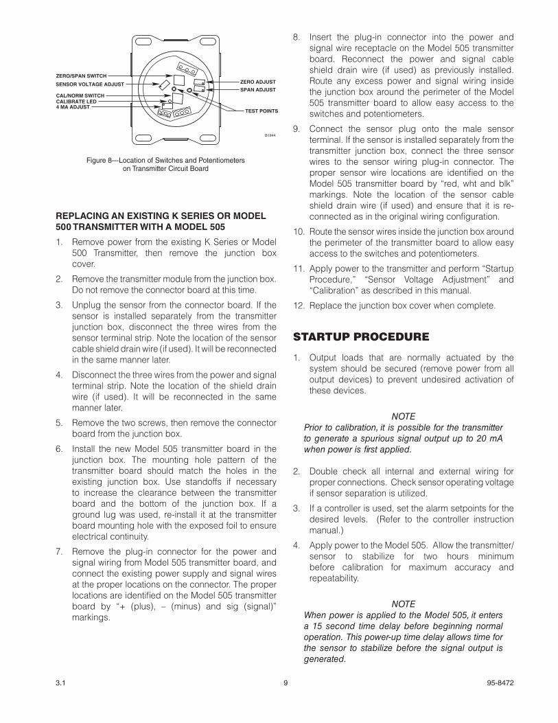
ZERO ADJUST
SPAN ADJUST
TEST POINTS
ZERO/SPAN SWITCH
SENSOR VOLTAGE ADJUST
CAL/NORM SWITCHCALIBRATE LED4 MA ADJUST
B1944
Figure 8—Location of Switches and Potentiometers on Transmitter Circuit Board
10 95-84723.1
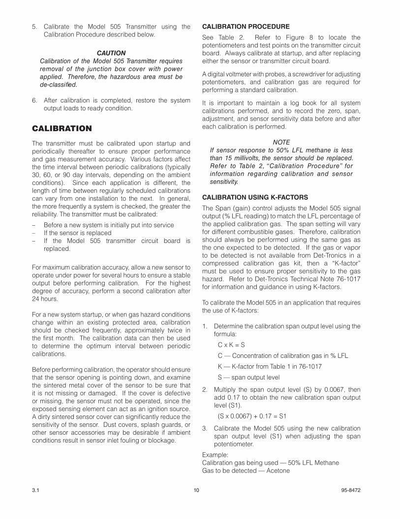
5. Calibrate the Model 505 Transmitter using the Calibration Procedure described below.
CAUTIONCalibration of the Model 505 Transmitter requires removal of the junction box cover with power applied. Therefore, the hazardous area must be de-classified.
6. After calibration is completed, restore the system output loads to ready condition.
CALIBRATION
The transmitter must be calibrated upon startup and periodically thereafter to ensure proper performance and gas measurement accuracy. Various factors affect the time interval between periodic calibrations (typically 30, 60, or 90 day intervals, depending on the ambient conditions). Since each application is different, the length of time between regularly scheduled calibrations can vary from one installation to the next. In general, the more frequently a system is checked, the greater the reliability. The transmitter must be calibrated:
– Before a new system is initially put into service – If the sensor is replaced – If the Model 505 transmitter circuit board is
replaced.
For maximum calibration accuracy, allow a new sensor to operate under power for several hours to ensure a stable output before performing calibration. For the highest degree of accuracy, perform a second calibration after 24 hours.
For a new system startup, or when gas hazard conditions change within an existing protected area, calibration should be checked frequently, approximately twice in the first month. The calibration data can then be used to determine the optimum interval between periodic calibrations.
Before performing calibration, the operator should ensure that the sensor opening is pointing down, and examine the sintered metal cover of the sensor to be sure that it is not missing or damaged. If the cover is defective or missing, the sensor must not be operated, since the exposed sensing element can act as an ignition source. A dirty sintered sensor cover can significantly reduce the sensitivity of the sensor. Dust covers, splash guards, or other sensor accessories may be desirable if ambient conditions result in sensor inlet fouling or blockage.
CALIBRATION PROCEDURE
See Table 2. Refer to Figure 8 to locate the potentiometers and test points on the transmitter circuit board. Always calibrate at startup, and after replacing either the sensor or transmitter circuit board.
A digital voltmeter with probes, a screwdriver for adjusting potentiometers, and calibration gas are required for performing a standard calibration.
It is important to maintain a log book for all system calibrations performed, and to record the zero, span, adjustment, and sensor sensitivity data before and after each calibration is performed.
NOTEIf sensor response to 50% LFL methane is less than 15 millivolts, the sensor should be replaced. Refer to Table 2, “Calibration Procedure” for information regarding calibration and sensor sensitivity.
CALIBRATION USING K-FACTORS
The Span (gain) control adjusts the Model 505 signal output (% LFL reading) to match the LFL percentage of the applied calibration gas. The span setting will vary for different combustible gases. Therefore, calibration should always be performed using the same gas as the one expected to be detected. If the gas or vapor to be detected is not available from Det-Tronics in a compressed calibration gas kit, then a “K-factor” must be used to ensure proper sensitivity to the gas hazard. Refer to Det-Tronics Technical Note 76-1017 for information and guidance in using K-factors.
To calibrate the Model 505 in an application that requires the use of K-factors:
1. Determine the calibration span output level using the formula:
C x K = S
C — Concentration of calibration gas in % LFL
K — K-factor from Table 1 in 76-1017
S — span output level
2. Multiply the span output level (S) by 0.0067, then add 0.17 to obtain the new calibration span output level (S1).
(S x 0.0067) + 0.17 = S1
3. Calibrate the Model 505 using the new calibration span output level (S1) when adjusting the span potentiometer.
Example:Calibration gas being used — 50% LFL MethaneGas to be detected — Acetone
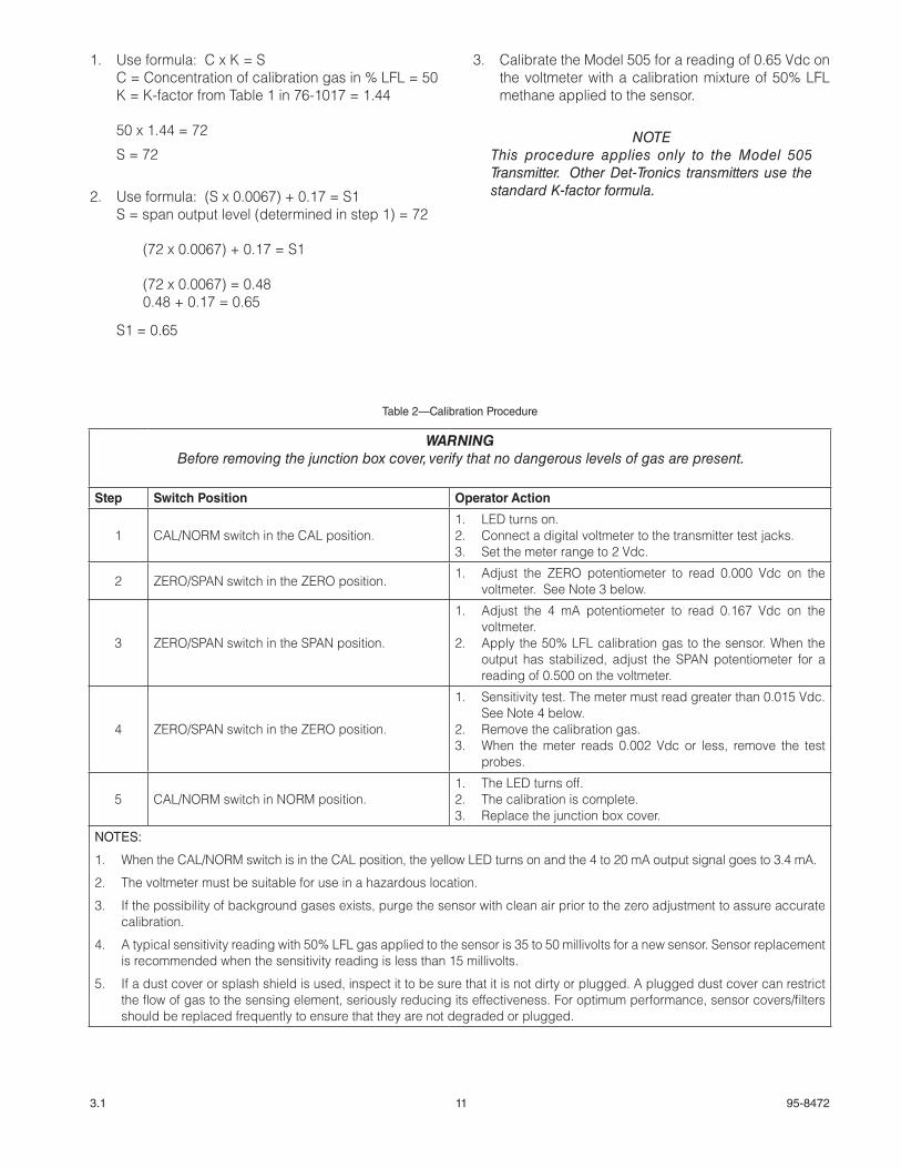
11 95-84723.1
1. Use formula: C x K = S C = Concentration of calibration gas in % LFL = 50 K = K-factor from Table 1 in 76-1017 = 1.44
50 x 1.44 = 72
S = 72
2. Use formula: (S x 0.0067) + 0.17 = S1 S = span output level (determined in step 1) = 72
(72 x 0.0067) + 0.17 = S1
(72 x 0.0067) = 0.480.48 + 0.17 = 0.65
S1 = 0.65
3. Calibrate the Model 505 for a reading of 0.65 Vdc on the voltmeter with a calibration mixture of 50% LFL methane applied to the sensor.
NOTEThis procedure applies only to the Model 505 Transmitter. Other Det-Tronics transmitters use the standard K-factor formula.
Table 2—Calibration Procedure
WARNINGBefore removing the junction box cover, verify that no dangerous levels of gas are present.
Step Switch Position Operator Action
1 CAL/NORM switch in the CAL position.1. LED turns on.2. Connect a digital voltmeter to the transmitter test jacks.3. Set the meter range to 2 Vdc.
2 ZERO/SPAN switch in the ZERO position. 1. Adjust the ZERO potentiometer to read 0.000 Vdc on the voltmeter. See Note 3 below.
3 ZERO/SPAN switch in the SPAN position.
1. Adjust the 4 mA potentiometer to read 0.167 Vdc on the voltmeter.
2. Apply the 50% LFL calibration gas to the sensor. When the output has stabilized, adjust the SPAN potentiometer for a reading of 0.500 on the voltmeter.
4 ZERO/SPAN switch in the ZERO position.
1. Sensitivity test. The meter must read greater than 0.015 Vdc. See Note 4 below.
2. Remove the calibration gas.3. When the meter reads 0.002 Vdc or less, remove the test
probes.
5 CAL/NORM switch in NORM position. 1. The LED turns off. 2. The calibration is complete.3. Replace the junction box cover.
NOTES:
1. When the CAL/NORM switch is in the CAL position, the yellow LED turns on and the 4 to 20 mA output signal goes to 3.4 mA.
2. The voltmeter must be suitable for use in a hazardous location.
3. If the possibility of background gases exists, purge the sensor with clean air prior to the zero adjustment to assure accurate calibration.
4. A typical sensitivity reading with 50% LFL gas applied to the sensor is 35 to 50 millivolts for a new sensor. Sensor replacement is recommended when the sensitivity reading is less than 15 millivolts.
5. If a dust cover or splash shield is used, inspect it to be sure that it is not dirty or plugged. A plugged dust cover can restrict the flow of gas to the sensing element, seriously reducing its effectiveness. For optimum performance, sensor covers/filters should be replaced frequently to ensure that they are not degraded or plugged.
12 95-84723.1
Section III — System Maintenance
TROUBLESHOOTING
Table 3 is intended to serve as an aid in locating the cause of a malfunction.
The transmitter is not designed to be repaired in the field. If a problem should develop, first check for proper wiring, calibration and sensor sensitivity. If it is determined that the problem is caused by an electrical malfunction in the transmitter, the unit must be returned to the factory for repair.
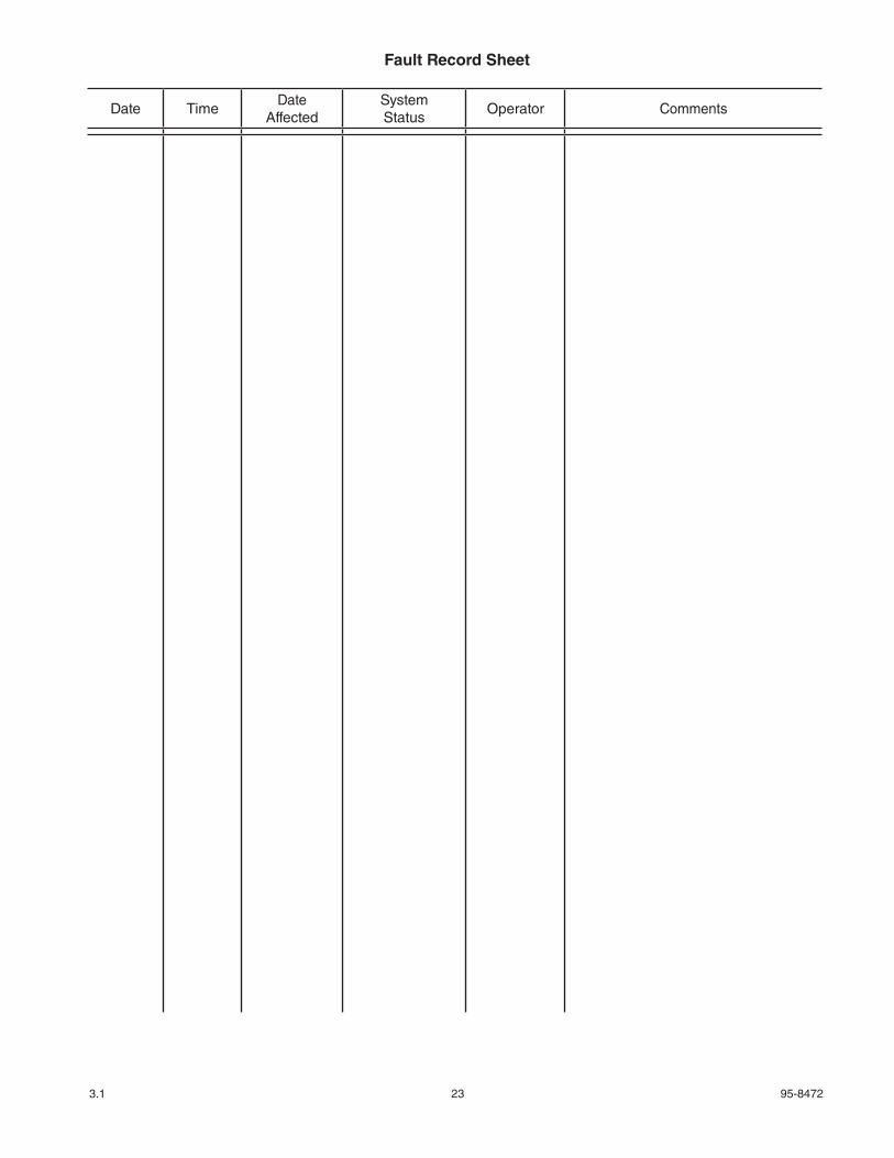
NOTERecord all faults on the Fault Record Sheet supplied at the back of this manual.
ROUTINE MAINTENANCE
The Model 505 Transmitter requires no routine maintenance, except for periodic checks to ensure proper calibration. The frequency of these checks is determined by the requirements of the particular installation. Calibration gas kits are required for these checks.
CHECKOUT IN NORMAL MODE
The entire gas detection system should be checked periodically to ensure that the presence of gas at the sensor will result in the proper system response.
SENSOR INSPECTION
Since a dirty or plugged sensor filter can adversely affect the response time of the sensor by restricting the flow of gas to the sensing element, it should be inspected on a regular basis. If a dust cover or splash shield is used, it should also be checked.
SENSOR SENSITIVITY
If sensor response to 50% LFL methane is less than 15 millivolts, the sensor should be replaced. Refer to Table 2, “Calibration Procedure” for information regarding calibration and sensor sensitivity.
SENSOR REPLACEMENT
De-classify the area prior to replacing the sensor and secure any output devices connected to the system to prevent unwanted actuation of this equipment. To replace the sensor:
1. Verify that no hazardous levels of combustible gas are present at the sensor, then remove the cover from the junction box.
2. Unplug the sensor from the circuit board and unscrew it from the junction box.
3. Coat the threads of the new sensor with silicone free grease, then screw the sensor into the junction box and plug it into the circuit board.
4. Allow the sensor output to stabilize under power (about two hours minimum for best results), then perform the calibration procedure described in the “Calibration” section of this manual.
5. For the highest degree of calibration accuracy, perform a second calibration after 24 hours.
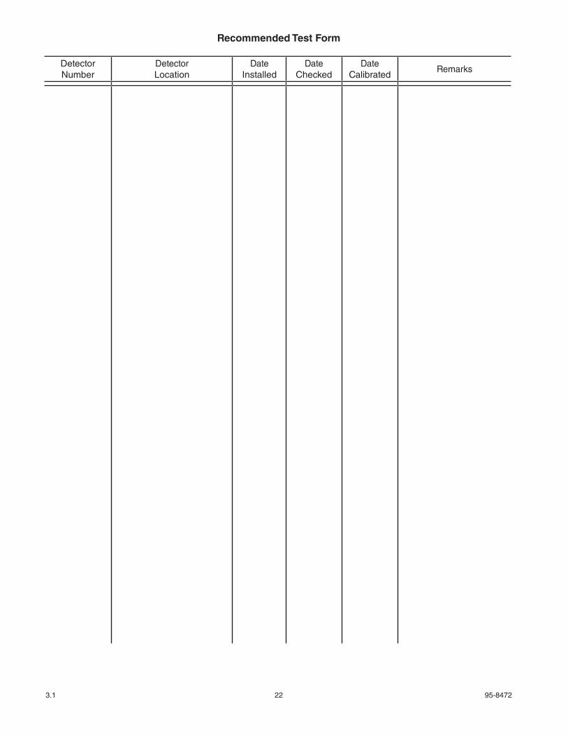
A Recommended Test Form is supplied at the back of this manual for recording maintenance performed on the system.
13 95-84723.1
REPLACEMENT PARTS
An adequate supply of spare sensors should be kept on hand for field replacement. For maximum protection against contamination and deterioration, they should not be removed from the original protective packaging until the time of installation.
Always calibrate after replacing either the sensor or the transmitter circuit board.
DEVICE REPAIR AND RETURN
Prior to returning devices, contact the nearest local Detector Electronics office so that a Return Material Identification (RMI) number can be assigned. A written statement describing the malfunction must accompany the returned device or component to assist and expedite finding the root cause of the failure.
Pack the unit properly. Always use sufficient packing material. Where applicable, use an antistatic bag as protection from electrostatic discharge.
NOTEDet-Tronics reserves the right to apply a service charge for repairing returned product damaged as a result of improper packaging.
Return all equipment transportation prepaid to the factory in Minneapolis.
NOTE It is highly recommended that a complete spare be kept on hand for field replacement to ensure continuous protection.
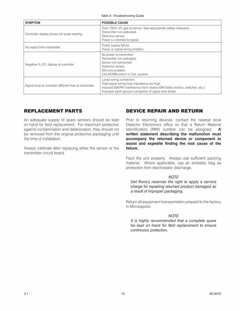
Table 3—Troubleshooting Guide
SYMPTOM POSSIBLE CAUSE
Controller display shows full scale reading
Over 100% LFL gas at sensor. Take appropriate safety measures.Transmitter not calibrated.Defective sensor.Power (+) shorted to signal.
No output from transmitterPower supply failure.Power or signal wiring problem.
Negative % LFL display at controller
No power to transmitter.Transmitter not calibrated.Sensor not connected.Defective sensor.SIG wire problem.CAL/NORM switch in CAL position.
Signal level at controller different than at transmitter
Loose wiring connection.Total signal wiring loop impedence too high.Induced EMI/RFI interference from nearby EMI fields (motors, switches, etc.).Improper earth ground connection of signal wire shield.
14 95-84723.1
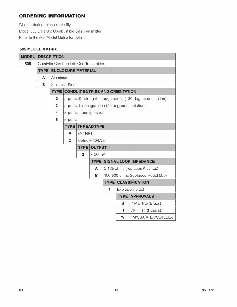
ORDERING INFORMATION
When ordering, please specifiy:
Model 505 Catalytic Combustible Gas Transmitter
Refer to the 505 Model Matrix for details
505 MODEL MATRIX
MODEL DESCRIPTION
505 Catalytic Combustible Gas Transmitter
TYPE ENCLOSURE MATERIAL
A Aluminum
S Stainless Steel
TYPE CONDUIT ENTRIES AND ORIENTATION
2 2-ports, ST-straight-through config (180 degree orientation)
3 2-ports, L-configuration (90 degree orientation)
4 3-ports, T-configuration
5 5-ports
TYPE THREAD TYPE
A 3/4" NPT
C Metric M20/M25
TYPE OUTPUT
2 4-20 mA
TYPE SIGNAL LOOP IMPEDANCE
A 0-125 ohms (replaces K series)
B 100-500 ohms (replaces Model 500)
TYPE CLASSIFICATION
1 Explosion-proof
TYPE APPROVALS
B INMETRO (Brazil)
R VNIIFTRI (Russia)
W FM/CSA/ATEX/CE/IECEx
15 95-84723.1
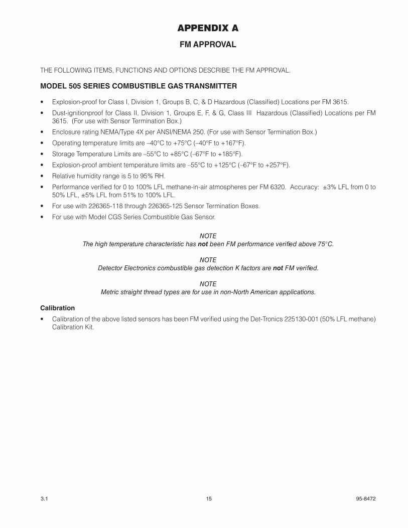
APPENDIX A
FM APPROVAL
THE FOLLOWING ITEMS, FUNCTIONS AND OPTIONS DESCRIBE THE FM APPROVAL.
MODEL 505 SERIES COMBUSTIBLE GAS TRANSMITTER
• Explosion-proof for Class I, Division 1, Groups B, C, & D Hazardous (Classified) Locations per FM 3615.
• Dust-ignitionproof for Class II, Division 1, Groups E, F, & G, Class III Hazardous (Classified) Locations per FM 3615. (For use with Sensor Termination Box.)
• Enclosure rating NEMA/Type 4X per ANSI/NEMA 250. (For use with Sensor Termination Box.)
• Operating temperature limits are –40°C to +75°C (–40°F to +167°F).
• Storage Temperature Limits are –55°C to +85°C (–67°F to +185°F).
• Explosion-proof ambient temperature limits are –55°C to +125°C (–67°F to +257°F).
• Relative humidity range is 5 to 95% RH.
• Performance verified for 0 to 100% LFL methane-in-air atmospheres per FM 6320. Accuracy: ±3% LFL from 0 to 50% LFL, ±5% LFL from 51% to 100% LFL.
• For use with 226365-118 through 226365-125 Sensor Termination Boxes.
• For use with Model CGS Series Combustible Gas Sensor.
NOTEThe high temperature characteristic has not been FM performance verified above 75°C.
NOTEDetector Electronics combustible gas detection K factors are not FM verified.
NOTEMetric straight thread types are for use in non-North American applications.
Calibration
• Calibration of the above listed sensors has been FM verified using the Det-Tronics 225130-001 (50% LFL methane) Calibration Kit.
16 95-84723.1
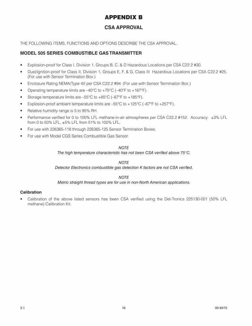
APPENDIX B
CSA APPROVAL
THE FOLLOWING ITEMS, FUNCTIONS AND OPTIONS DESCRIBE THE CSA APPROVAL.
MODEL 505 SERIES COMBUSTIBLE GAS TRANSMITTER
• Explosion-proof for Class I, Division 1, Groups B, C, & D Hazardous Locations per CSA C22.2 #30.
• Dust/ignition-proof for Class II, Division 1, Groups E, F, & G, Class III Hazardous Locations per CSA C22.2 #25. (For use with Sensor Termination Box.)
• Enclosure Rating NEMA/Type 4X per CSA C22.2 #94. (For use with Sensor Termination Box.)
• Operating temperature limits are –40°C to +75°C (–40°F to +167°F).
• Storage temperature limits are –55°C to +85°C (–67°F to +185°F).
• Explosion-proof ambient temperature limits are –55°C to +125°C (–67°F to +257°F).
• Relative humidity range is 5 to 95% RH.
• Performance verified for 0 to 100% LFL methane-in-air atmospheres per CSA C22.2 #152. Accuracy: ±3% LFL from 0 to 50% LFL, ±5% LFL from 51% to 100% LFL.
• For use with 226365-118 through 226365-125 Sensor Termination Boxes.
• For use with Model CGS Series Combustible Gas Sensor.
NOTEThe high temperature characteristic has not been CSA verified above 75°C.
NOTEDetector Electronics combustible gas detection K factors are not CSA verified.
NOTEMetric straight thread types are for use in non-North American applications.
Calibration
• Calibration of the above listed sensors has been CSA verified using the Det-Tronics 225130-001 (50% LFL methane) Calibration Kit.
17 95-84723.1
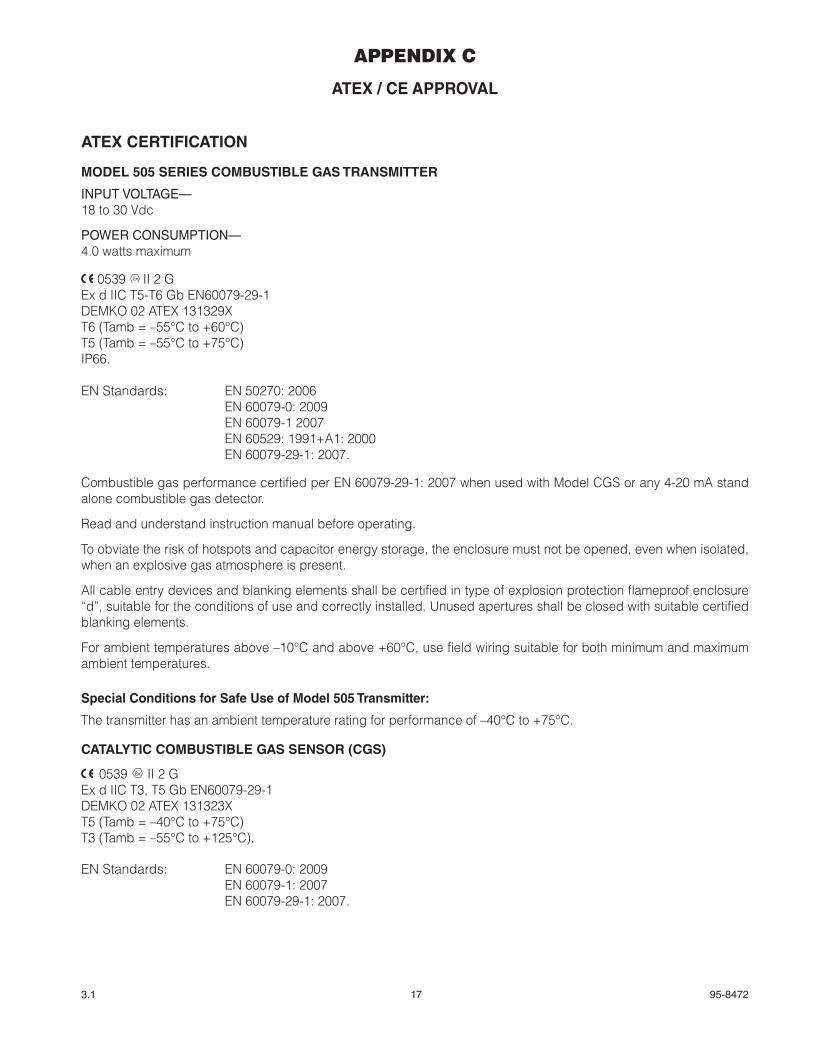
APPENDIX C
ATEX / CE APPROVAL
ATEX CERTIFICATION
MODEL 505 SERIES COMBUSTIBLE GAS TRANSMITTER
INPUT VOLTAGE—18 to 30 Vdc
POWER CONSUMPTION—4.0 watts maximum
0539 FMAPPROVED
® II 2 GEx d IIC T5-T6 Gb EN60079-29-1DEMKO 02 ATEX 131329XT6 (Tamb = –55°C to +60°C)T5 (Tamb = –55°C to +75°C)IP66.
EN Standards: EN 50270: 2006 EN 60079-0: 2009 EN 60079-1 2007 EN 60529: 1991+A1: 2000 EN 60079-29-1: 2007.
Combustible gas performance certified per EN 60079-29-1: 2007 when used with Model CGS or any 4-20 mA stand alone combustible gas detector.
Read and understand instruction manual before operating.
To obviate the risk of hotspots and capacitor energy storage, the enclosure must not be opened, even when isolated, when an explosive gas atmosphere is present.
All cable entry devices and blanking elements shall be certified in type of explosion protection flameproof enclosure “d”, suitable for the conditions of use and correctly installed. Unused apertures shall be closed with suitable certified blanking elements.
For ambient temperatures above –10°C and above +60°C, use field wiring suitable for both minimum and maximum ambient temperatures.
Special Conditions for Safe Use of Model 505 Transmitter:
The transmitter has an ambient temperature rating for performance of –40°C to +75°C.
CATALYTIC COMBUSTIBLE GAS SENSOR (CGS)
0539 FMAPPROVED
® II 2 GEx d IIC T3, T5 Gb EN60079-29-1DEMKO 02 ATEX 131323XT5 (Tamb = –40°C to +75°C)T3 (Tamb = –55°C to +125°C).
EN Standards: EN 60079-0: 2009 EN 60079-1: 2007 EN 60079-29-1: 2007.
18 95-84723.1
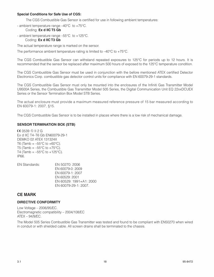
Special Conditions for Safe Use of CGS:
The CGS Combustible Gas Sensor is certified for use in following ambient temperatures:
- ambient temperature range –40°C to +75°C. Coding: Ex d IIC T5 Gb
- ambient temperature range –55°C to +125°C. Coding: Ex d IIC T3 Gb
The actual temperature range is marked on the sensor.
The performance ambient temperature rating is limited to –40°C to +75°C.
The CGS Combustible Gas Sensor can withstand repeated exposures to 125°C for periods up to 12 hours. It is recommended that the sensor be replaced after maximum 500 hours of exposed to the 125°C temperature condition. The CGS Combustible Gas Sensor must be used in conjunction with the before mentioned ATEX certified Detector Electronics Corp. combustible gas detector control units for compliance with EN 60079-29-1 standards.
The CGS Combustible Gas Sensor must only be mounted into the enclosures of the Infiniti Gas Transmitter Model U9500A Series, the Combustible Gas Transmitter Model 505 Series, the Digital Communication Unit EQ 22xxDCUEX Series or the Sensor Termination Box Model STB Series.
The actual enclosure must provide a maximum measured reference pressure of 15 bar measured according to EN 60079-1: 2007, §15.
The CGS Combustible Gas Sensor is to be installed in places where there is a low risk of mechanical damage.
SENSOR TERMINATION BOX (STB)
0539 FMAPPROVED
® II 2 GEx d IIC T4–T6 Gb EN60079-29-1DEMKO 02 ATEX 131324XT6 (Tamb = –55°C to +60°C).T5 (Tamb = –55°C to +75°C).T4 (Tamb = –55°C to +125°C).IP66.
EN Standards: EN 50270: 2006 EN 60079-0: 2009 EN 60079-1: 2007 EN 60529: 2001 EN 60529: 1991+A1: 2000 EN 60079-29-1: 2007.
CE MARK
DIRECTIVE CONFORMITY
Low Voltage – 2006/95/EC.Electromagnetic compatibility – 2004/108/ECATEX – 94/9/EC.
The Model 505 Series Combustible Gas Transmitter was tested and found to be compliant with EN50270 when wired in conduit or with shielded cable. All screen drains shall be terminated to the chassis.
19 95-84723.1
APPENDIX D
IECEx APPROVAL
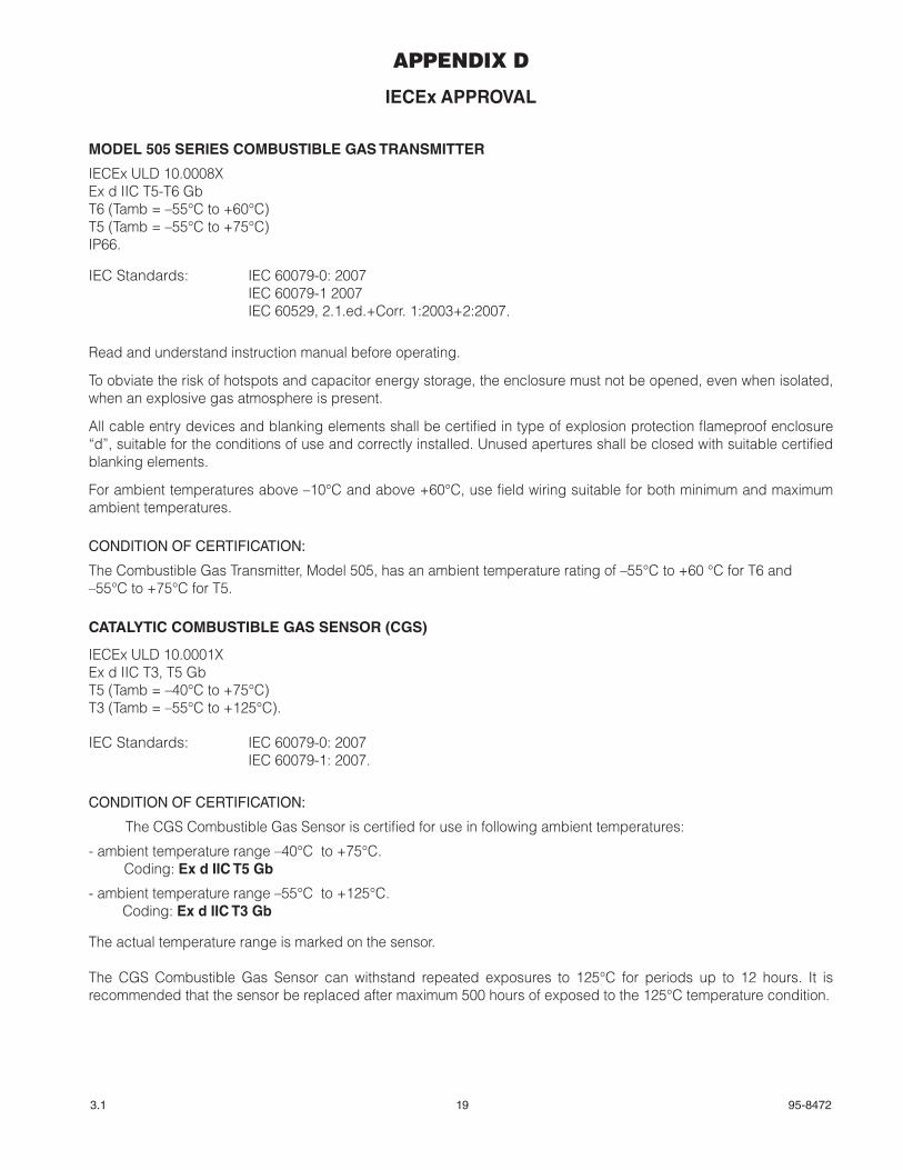
MODEL 505 SERIES COMBUSTIBLE GAS TRANSMITTER
IECEx ULD 10.0008XEx d IIC T5-T6 GbT6 (Tamb = –55°C to +60°C)T5 (Tamb = –55°C to +75°C)IP66.
IEC Standards: IEC 60079-0: 2007 IEC 60079-1 2007 IEC 60529, 2.1.ed.+Corr. 1:2003+2:2007.
Read and understand instruction manual before operating.
To obviate the risk of hotspots and capacitor energy storage, the enclosure must not be opened, even when isolated, when an explosive gas atmosphere is present.
All cable entry devices and blanking elements shall be certified in type of explosion protection flameproof enclosure “d”, suitable for the conditions of use and correctly installed. Unused apertures shall be closed with suitable certified blanking elements.
For ambient temperatures above –10°C and above +60°C, use field wiring suitable for both minimum and maximum ambient temperatures.
CONDITION OF CERTIFICATION:
The Combustible Gas Transmitter, Model 505, has an ambient temperature rating of –55°C to +60 °C for T6 and –55°C to +75°C for T5.
CATALYTIC COMBUSTIBLE GAS SENSOR (CGS)
IECEx ULD 10.0001XEx d IIC T3, T5 GbT5 (Tamb = –40°C to +75°C)T3 (Tamb = –55°C to +125°C).
IEC Standards: IEC 60079-0: 2007 IEC 60079-1: 2007.
CONDITION OF CERTIFICATION:
The CGS Combustible Gas Sensor is certified for use in following ambient temperatures:
- ambient temperature range –40°C to +75°C. Coding: Ex d IIC T5 Gb
- ambient temperature range –55°C to +125°C. Coding: Ex d IIC T3 Gb
The actual temperature range is marked on the sensor.
The CGS Combustible Gas Sensor can withstand repeated exposures to 125°C for periods up to 12 hours. It is recommended that the sensor be replaced after maximum 500 hours of exposed to the 125°C temperature condition.
20 95-84723.1
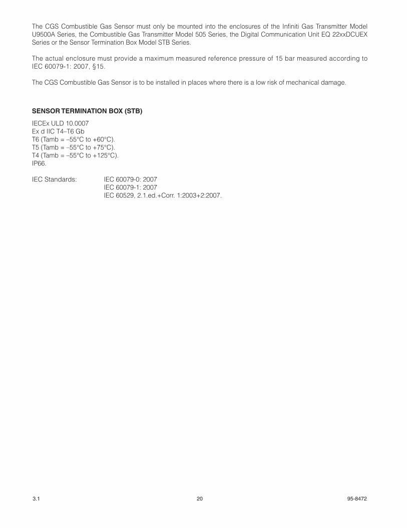
The CGS Combustible Gas Sensor must only be mounted into the enclosures of the Infiniti Gas Transmitter Model U9500A Series, the Combustible Gas Transmitter Model 505 Series, the Digital Communication Unit EQ 22xxDCUEX Series or the Sensor Termination Box Model STB Series.
The actual enclosure must provide a maximum measured reference pressure of 15 bar measured according to IEC 60079-1: 2007, §15.
The CGS Combustible Gas Sensor is to be installed in places where there is a low risk of mechanical damage.
SENSOR TERMINATION BOX (STB)
IECEx ULD 10.0007Ex d IIC T4–T6 GbT6 (Tamb = –55°C to +60°C).T5 (Tamb = –55°C to +75°C).T4 (Tamb = –55°C to +125°C).IP66.
IEC Standards: IEC 60079-0: 2007 IEC 60079-1: 2007 IEC 60529, 2.1.ed.+Corr. 1:2003+2:2007.
21 95-84723.1
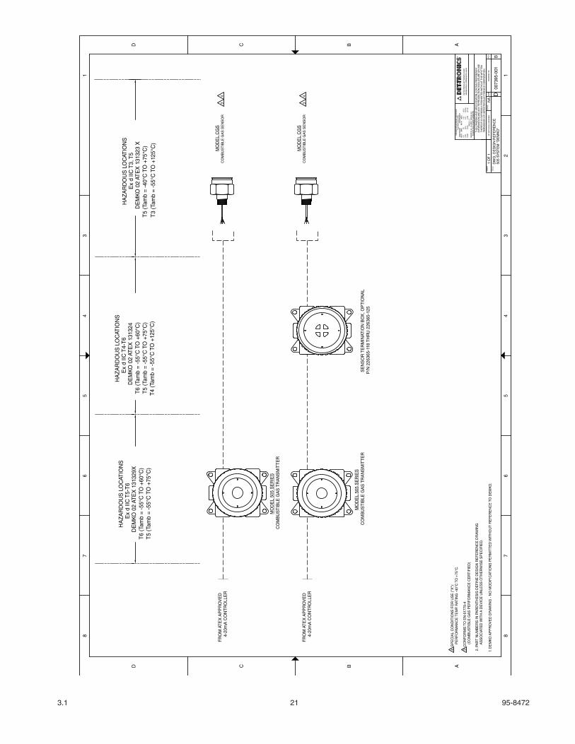
CO
MB
US
TIB
LE G
AS
TR
AN
SM
ITT
ER
SE
NS
OR
TE
RM
INAT
ION
BO
X, O
PT
ION
AL
0073
95-0
0150
5 S
YST
EM
"D
EM
KO
"
NA
DW
G, D
ES
IGN
RE
FE
RE
NC
E
1 O
F 1
B1.
DE
MK
O A
PP
RO
VE
D D
RA
WIN
G -
NO
MO
DIF
ICAT
ION
S P
ER
MIT
TE
D W
ITH
OU
T R
EF
ER
EN
CE
TO
DE
MK
O.
FR
OM
AT
EX
AP
PR
OV
ED
CO
MB
US
TIB
LE G
AS
TR
AN
SM
ITT
ER
P/N
226
365-
118
TH
RU
226
365-
125
4-20
mA
CO
NT
RO
LLE
R
4-20
mA
CO
NT
RO
LLE
R
CO
MB
US
TIB
LE G
AS
SE
NS
OR
MO
DE
L 50
5 S
ER
IES
MO
DE
L 50
5 S
ER
IES
MO
DE
L C
GS
8
D C B A
D C B A
8
7 7
6 6
5 5
4 4
3 32
1 1
D
TH
ER
EO
F IS
EX
PR
ES
SLY
PR
OH
IBIT
ED
WIT
HO
UT
TH
E W
RIT
TE
N
UN
LES
S O
TH
ER
WIS
E S
PE
CIF
IED
DIM
EN
SIO
N
TO
LER
AN
CE
INC
H
(M
M)
I
NC
H
(M
M)
RE
MO
VE
ALL
BU
RR
S B
RE
AK
ALL
ED
GE
S A
ND
SH
AR
P C
OR
NE
RS
TH
IS D
RA
WIN
G A
ND
SP
EC
IFIC
ATIO
N C
ON
TAIN
PR
OP
RIE
TAR
YIN
FO
RM
ATIO
N A
ND
AN
Y R
EP
RO
DU
CT
ION
DIS
CLO
SU
RE
OR
US
E
PE
RM
ISS
ION
OF
DE
TE
CTO
R E
LEC
TR
ON
ICS
CO
RP
OR
ATIO
N.
0.0
(0)
±.02
TIT
LE
SH
EE
TD
O N
OT
SC
ALE
DR
AW
ING
AN
GLE
±1'
(0.0
)(0
.00)
0.00
0.00
0 ±.
01±.
005
TOLE
RA
NC
ES
AR
E :
DE
TE
CTO
R E
LEC
TR
ON
ICS
CO
RP.
±(0.
5)
SIZ
ES
CA
LED
RA
WIN
G N
O.
MIN
NE
AP
OLI
S, M
INN
ES
OTA
554
38±(
0.25
)±(
0.13
)
RE
V
3 C
ON
FO
RM
S T
O E
N 6
1779
-4(C
OM
BU
ST
IBLE
GA
S P
ER
FO
RM
AN
CE
CE
RT
IFIE
D)
FR
OM
AT
EX
AP
PR
OV
ED
3
CO
MB
US
TIB
LE G
AS
SE
NS
OR
MO
DE
L C
GS
HA
ZA
RD
OU
S L
OC
ATIO
NS
Ex
d IIC
T4-
T6
DE
MK
O 0
2 AT
EX
131
324
T6
(Tam
b =
-55°
C T
O +
60°C
)T
5 (T
amb
= -5
5°C
TO
+75
°C)
T4
(Tam
b =
-55°
C T
O +
125°
C)
HA
ZA
RD
OU
S L
OC
ATIO
NS
Ex
d IIC
T5-
T6
DE
MK
O 0
2 AT
EX
131
329X
T6
(Tam
b =
-55°
C T
O +
60°C
)T
5 (T
amb
= -5
5°C
TO
+75
°C)
AS
SO
CIA
TE
D W
ITH
A D
EV
ICE
UN
LES
S O
TH
ER
WIS
E S
PE
CIF
IED
.2.
PA
RT
NU
MB
ER
S IN
PA
RE
NT
HE
SIS
DE
FIN
E D
ES
IGN
RE
FE
RE
NC
E D
RA
WIN
G
3
44
PE
RF
OR
MA
NC
E T
EM
P. R
ATIN
G -
40°C
TO
+75
°C.
4 S
PE
CIA
L C
ON
DIT
ION
S F
OR
US
E (
"X")
:
HA
ZA
RD
OU
S L
OC
ATIO
NS
Ex
d IIC
T3,
T5
DE
MK
O 0
2 AT
EX
131
323
XT
5 (T
amb
= -4
0°C
TO
+75
°C)
T3
(Tam
b =
-55°
C T
O +
125°
C)
22 95-84723.1
Recommended Test Form
DetectorNumber
Detector Location
Date Installed
DateChecked
Date Calibrated
Remarks
23 95-84723.1
Fault Record Sheet
Date TimeDate
AffectedSystemStatus
Operator Comments
Detector Electronics Corporation6901 West 110th Street
Minneapolis, MN 55438 USA
T: 952.941.5665 or 800.765.3473F: 952.829.8750
W: http://www.det-tronics.comE: [email protected]
Det-Tronics, the DET-TRONICS logo, Eagle Quantum Premier, and PointWatch Eclipse are registered trademarks or trademarks of Detector Electronics Corporation in the United States, other countries, or both. Other company, product, or service names may be trademarks or service marks of others.
© Copyright Detector Electronics Corporation 2012. All rights reserved.
95-8472
X3301 Multispectrum IR Flame Detector
PointWatch Eclipse® IR Combustible Gas Detector
Eagle Quantum Premier® Safety System
FlexVu® Universal Displayw/ GT3000 Toxic Gas Detector