Embed Size (px)
Citation preview
THE CITADEL, THE MILITARY COLLEGE OF SOUTH CAROLINA
171 Moultrie Street, Charleston, SC 29409
Instructional Demos, In-Class Projects,
& Hands-On Homework:
Active Learning for Electrical Engineering
using the Analog Discovery
by
Dr. Gregory J. Mazzaro
Dr. Ronald J. Hayne
2
Presentation Overview
• Motivations for Introducing the Analog Discovery into EE Courses
• Key Features of the 1st-Generation Unit Manufactured by Digilent
• Hardware and Software
• Analog and Digital
• Integration of the Analog Discovery into Citadel EE
• Freshman Introduction to Electrical Engineering
• Sophomore Circuit Analysis and Digital Logic
• Results, Feedback, & Summary
3
Why use the Analog Discovery?
(1) to provide hands-on exposure that few EE students receive
in the opening semesters of their major
(2) to introduce electrical wiring/routing, signals, and components
to a student who has not yet studied Ohm’s Law
(3) to provide a way for students to experiment with relatively-harmless
electricity away from the classroom and lab
(4) to integrate such a tool across multiple core EE courses
(5) to familiarize EE students with a tool that they
might use to complete assignments/designs
that do not require using the Analog Discovery
(6) to accomplish [all of the above] for under $200
• Motivations for Introducing the Analog Discovery into EE Courses
4
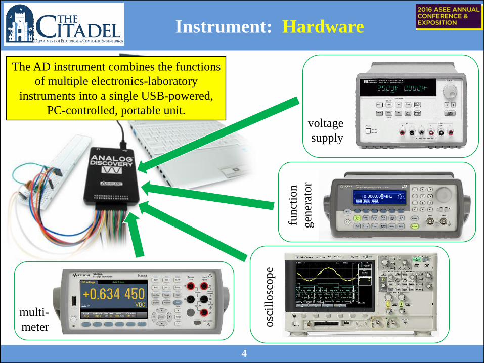
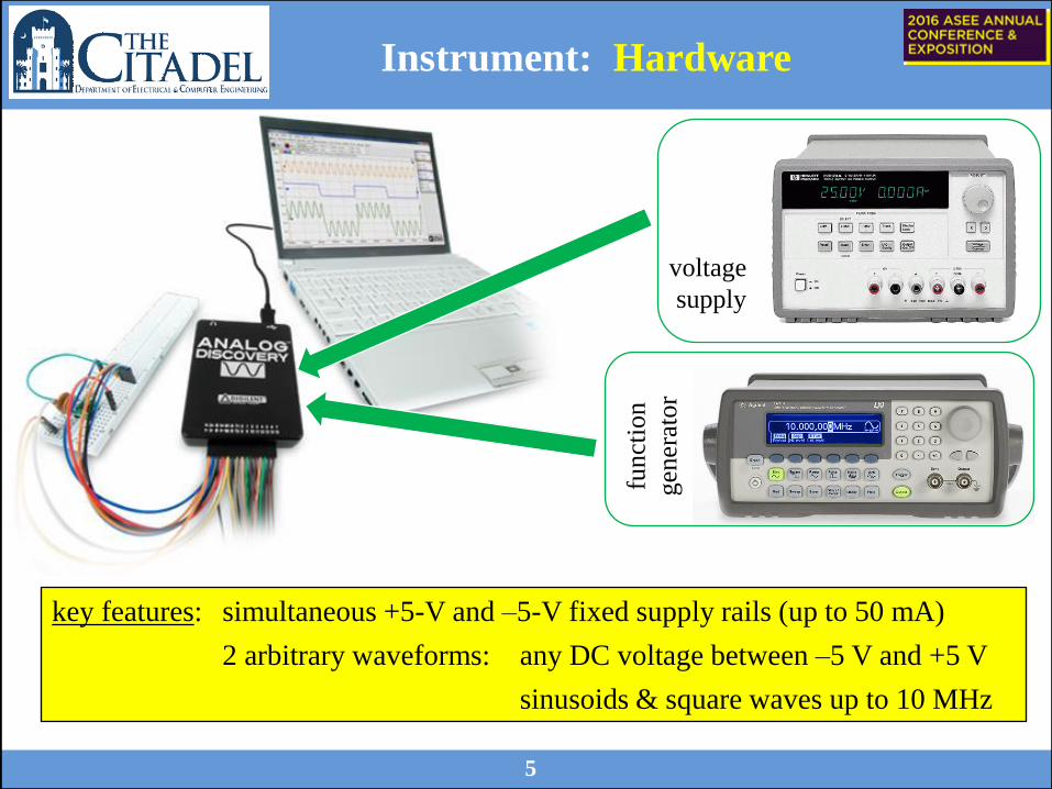
Instrument: Hardware
voltage
supply
osc
illo
scop
e
fun
ctio
n
gen
erat
or
multi-
meter
The AD instrument combines the functions
of multiple electronics-laboratory
instruments into a single USB-powered,
PC-controlled, portable unit.
5
Instrument: Hardware
voltage
supply
fun
ctio
n
gen
erat
or
key features: simultaneous +5-V and –5-V fixed supply rails (up to 50 mA)
2 arbitrary waveforms: any DC voltage between –5 V and +5 V
sinusoids & square waves up to 10 MHz
6
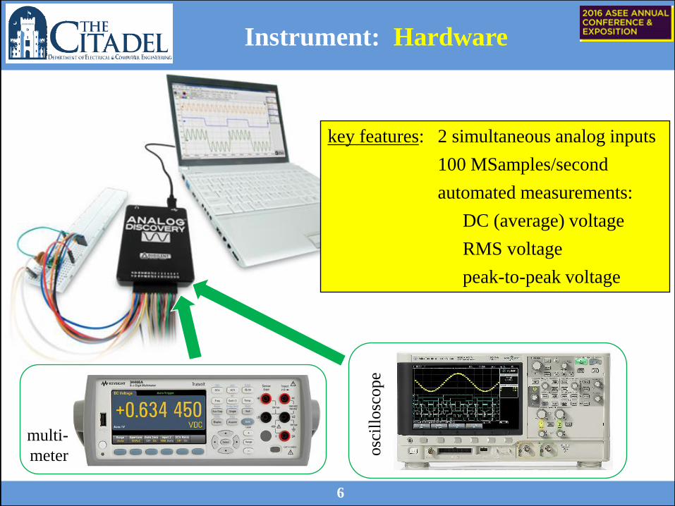
Instrument: Hardware
osc
illo
scop
e
multi-
meter
key features: 2 simultaneous analog inputs
100 MSamples/second
automated measurements:
DC (average) voltage
RMS voltage
peak-to-peak voltage
7
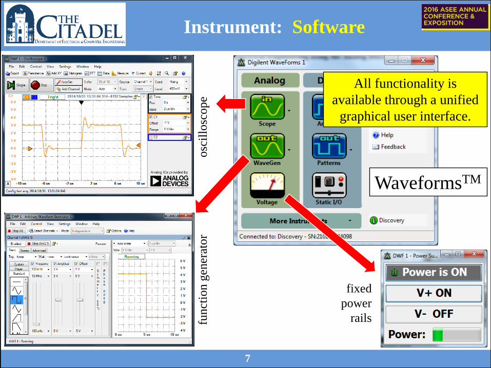
Instrument: Software
WaveformsTM
osc
illo
scope
fixed
power
rails funct
ion g
ener
ator
All functionality is
available through a unified
graphical user interface.

8
Instrument: Software
WaveformsTM
multimeter
static input/output logic analyzer
logic pattern generator
All functionality is
available through a unified
graphical user interface.
9
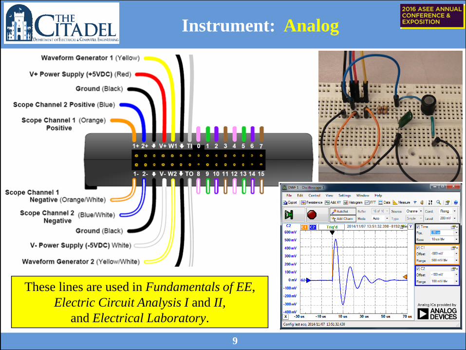
Instrument: Analog
These lines are used in Fundamentals of EE,
Electric Circuit Analysis I and II,
and Electrical Laboratory.
10
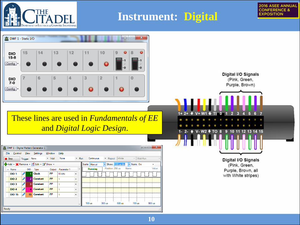
Instrument: Digital
These lines are used in Fundamentals of EE
and Digital Logic Design.
11
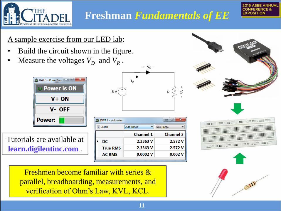
Freshman Fundamentals of EE
5 V R
+ VD -
ID
+ V
R -
Freshmen become familiar with series &
parallel, breadboarding, measurements, and
verification of Ohm’s Law, KVL, KCL.
A sample exercise from our LED lab:
• Build the circuit shown in the figure.
• Measure the voltages VD and VR .
Tutorials are available at
learn.digilentinc.com .
12
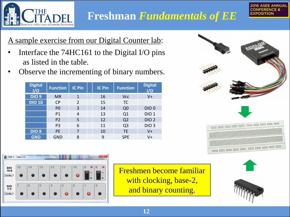
Digital I/O
Function IC Pin IC Pin Function Digital
I/O
DIO 9 MR 1 16 Vcc V+
DIO 10 CP 2 15 TC P0 3 14 Q0 DIO 0
P1 4 13 Q1 DIO 1
P2 5 12 Q2 DIO 2
P3 6 11 Q3 DIO 3
DIO 8 PE 7 10 TE V+
GND GND 8 9 SPE V+
Freshman Fundamentals of EE
A sample exercise from our Digital Counter lab:
• Interface the 74HC161 to the Digital I/O pins
as listed in the table.
• Observe the incrementing of binary numbers.
Freshmen become familiar
with clocking, base-2,
and binary counting.
13
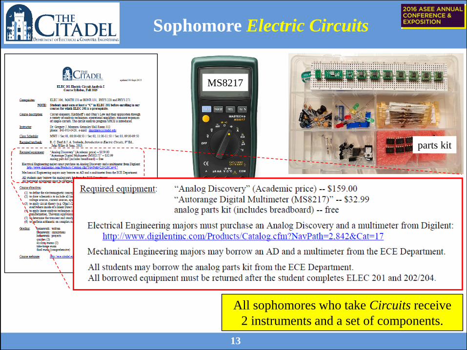
Sophomore Electric Circuits
All sophomores who take Circuits receive
2 instruments and a set of components.
MS8217
parts kit
Sophomore Electric Circuits
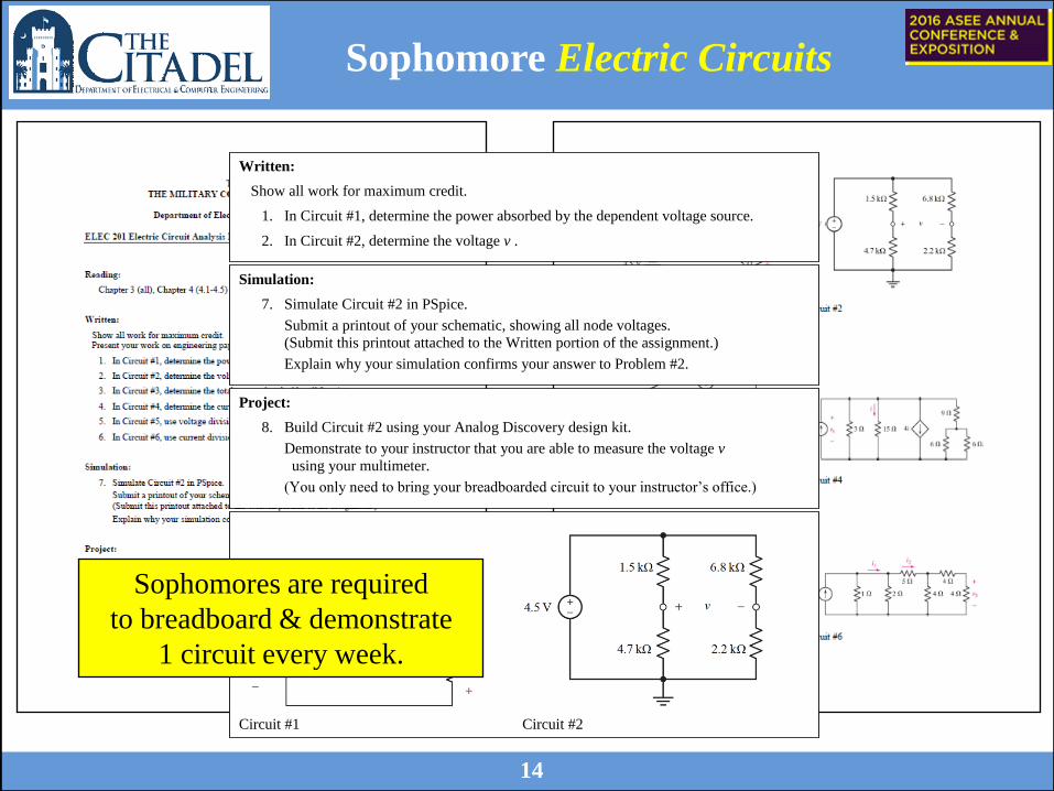
Written:
Show all work for maximum credit.
1. In Circuit #1, determine the power absorbed by the dependent voltage source.
2. In Circuit #2, determine the voltage v .
Simulation:
7. Simulate Circuit #2 in PSpice.
Submit a printout of your schematic, showing all node voltages.
(Submit this printout attached to the Written portion of the assignment.)
Explain why your simulation confirms your answer to Problem #2.
Project:
8. Build Circuit #2 using your Analog Discovery design kit.
Demonstrate to your instructor that you are able to measure the voltage v
using your multimeter.
(You only need to bring your breadboarded circuit to your instructor’s office.)
Circuit #1 Circuit #2
14
Sophomores are required
to breadboard & demonstrate
1 circuit every week.
15
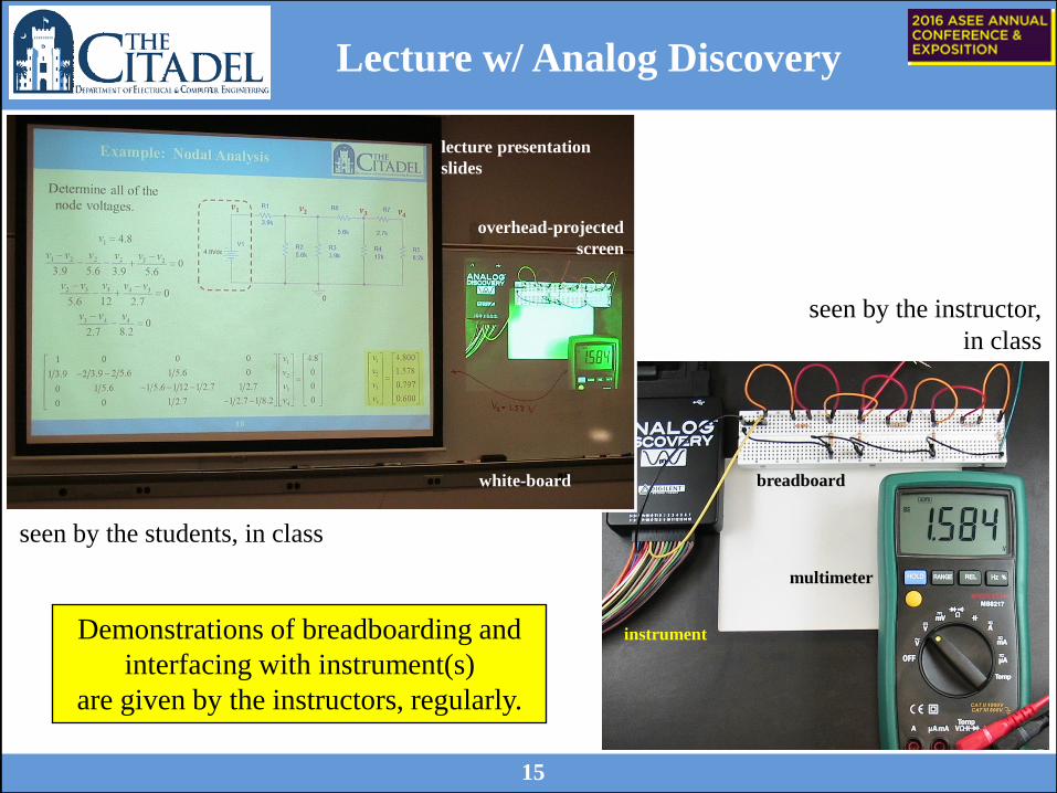
Lecture w/ Analog Discovery
instrument
breadboard
multimeter
white-board
overhead-projected
screen
lecture presentation
slides
seen by the students, in class
seen by the instructor,
in class
Demonstrations of breadboarding and
interfacing with instrument(s)
are given by the instructors, regularly.
16
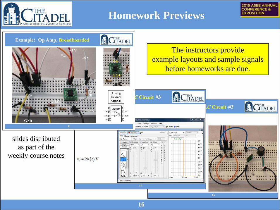
Homework Previews
slides distributed
as part of the
weekly course notes
The instructors provide
example layouts and sample signals
before homeworks are due.
17
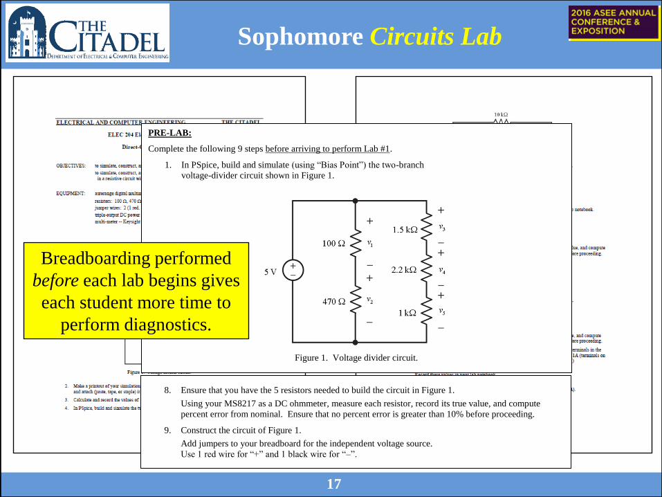
Sophomore Circuits Lab
PRE-LAB:
Complete the following 9 steps before arriving to perform Lab #1.
1. In PSpice, build and simulate (using “Bias Point”) the two-branch
voltage-divider circuit shown in Figure 1.
Figure 1. Voltage divider circuit.
8. Ensure that you have the 5 resistors needed to build the circuit in Figure 1.
Using your MS8217 as a DC ohmmeter, measure each resistor, record its true value, and compute
percent error from nominal. Ensure that no percent error is greater than 10% before proceeding.
9. Construct the circuit of Figure 1.
Add jumpers to your breadboard for the independent voltage source.
Use 1 red wire for “+” and 1 black wire for “–”.
Breadboarding performed
before each lab begins gives
each student more time to
perform diagnostics.
18
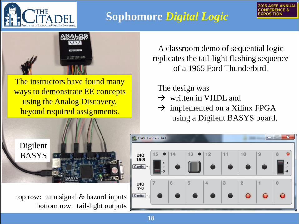
Sophomore Digital Logic
A classroom demo of sequential logic
replicates the tail-light flashing sequence
of a 1965 Ford Thunderbird.
The design was
written in VHDL and
implemented on a Xilinx FPGA
using a Digilent BASYS board.
Digilent
BASYS
The instructors have found many
ways to demonstrate EE concepts
using the Analog Discovery,
beyond required assignments.
top row: turn signal & hazard inputs
bottom row: tail-light outputs
19
Results / Successes
Outcomes required by ABET:
• “an ability to apply knowledge of mathematics, science, and
engineering” -- Students use the Analog Discovery to verify theoretical
results given by KVL, KCL, and calculus.
• “an ability to design and conduct experiments, as well as to analyze and
interpret data” -- Students can now conduct such experiments (partly)
on their own time, in their choice of environment.
• “an ability to use the techniques, skills, and modern engineering tools
necessary for engineering practice” -- Modern EE is performed by
comparing simulations against measurements, such as PSpice vs. Analog
Discovery results
20
Results / Successes
Proficiencies demonstrated by our students:
in Fundamentals of Electrical Engineering …
• build a resistor-LED circuit
• measure a DC voltage & calculate a DC current
• build an IC-based counter circuit
• control digital inputs & observe digital outputs
in Electric Circuit Analysis I …
• measure a resistance
• breadboard a resistive circuit
• measure multiple DC voltages; measure a DC current
• build a circuit containing multiple sources / an op amp
• generate and observe a sinusoid & a square-wave voltage
• build an RC/RL circuit; observe an exponential rise/decay
21
Feedback & Summary
Feedback reported by students:
from Fundamentals of Electrical Engineering …
• “The course did a good job holding my attention. Everything was
interesting and hands-on.”
• “I enjoyed the hands-on learning style of the labs and lessons.”
from Electric Circuit Analysis I …
• “I enjoyed the demo assignments in the course. Hands-on homework
with the breadboard and PSpice was very helpful.”
• I love the Digilent-Waveforms projects as well as the PSpice
simulations. This really helped me understand key concepts.”
Summary: We demonstrated the integration of the Analog Discovery
across the early EE undergraduate curriculum.
The AD does help to achieve ABET’s stated objectives for EEs
and has received a positive response from students.
22
References
[1] Analog Discovery Technical Reference Manual, Digilent Inc., 2013.
[2] Waveforms SDK manual, Digilent Inc., 2015.
[3] Beginner Analog Discovery, Module 1,
https://learn.digilentinc.com/Module/104 , 2016.
[4] Getting Started with the Analog Discovery,
https://www.youtube.com/user/DigilentInc/playlists , 2016.
[5] Digilent Basys Board Reference Manual, Digilent Inc., 2007.