Embed Size (px)
DESCRIPTION
http://www.gea.com/global/en/binaries/Instruction%20Manual%20%E2%80%93%20GEA%20Omni%E2%84%A2%20control%20panel_tcm11-27711.pdf
Citation preview
Control panelGEA Omni™
Instruction Manual806550_1
COPYRIGHTAll Rights reserved.No part of this publication may be copied or pub-lished by means of printing, photocopying, microfilmor otherwise without prior written consent of
• GEA Refrigeration North America, Inc.herein after called manufacturer. This restrictionalso applies to the corresponding drawings and dia-grams.
LEGAL NOTICEThis product information is a part of the documenta-tion for the GEA Omni™ scope of delivery andserves as product presentation and customer advi-sory service. It contains important information andtechnical data regarding the product.The product information makes the technical, prod-uct related and commercial information available tothe customer in detail before the sale of the product.This product information serves as a support andtechnical advisory service for our partners and cus-tomers as well as for the marketing team. Apart fromserving as the medium for transfer of product know-how, it also forms the basis for product demonstra-tions, the organization and conduction of technicalseminars as well as the technical support at tradefairs.This product information should be supplementedwith the information about the industrial safety andhealth related regulations at the site of installation ofthe product. The regulations vary form place to placeas a result of the statutory regulations applicable atthe site of installation of the product and are there-fore have not been considered in this product infor-mation.In addition to this product information and the acci-dent prevention regulations applicable for therespective country and area where the product isused, the accepted technical regulations for safe andprofessional work must also be observed.This product information has been written in goodfaith. However, the manufacturer cannot be heldresponsible for any errors that this document maycontain or for their consequences.
The manufacturer reserves the right to make techni-cal changes during the course of further develop-ment of the GEA Omni™ shown in this product infor-mation.Illustrations and drawings in this product informationare simplified representations. As a result of theimprovements and changes, it is possible that theillustrations do not exactly match the current devel-opment status. The technical data and dimensionsare subject to change and claims can be made onthe basis of them.
Instruction Manual | GEA Omni™Control panel
2 GEA Refrigeration North America, Inc. | 806550_1 | Generated 21.01.2015
SYMBOLS USED IN THIS MANUALDanger!
Stands for an immediate danger whichleads to heavy physical injuries or tothe death.
Warning!
Stands for a possibly dangerous situa-tion which leads to heavy physicalinjuries or to the death.
Caution!
Stands for a possibly dangerous situa-tion which could lead to light physicalinjuries or to damages to property.
Hint!
Stands for an important tip whoseattention is important for the desig-nated use and function of the device.
Instruction Manual | GEA Omni™Control panel
GEA Refrigeration North America, Inc. | 806550_1 | Generated 21.01.2015 3

Instruction Manual | GEA Omni™Control panel
4 GEA Refrigeration North America, Inc. | 806550_1 | Generated 21.01.2015
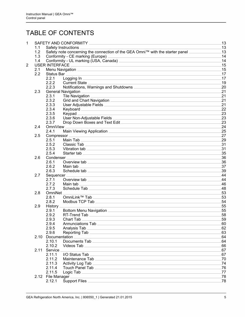
TABLE OF CONTENTS1 SAFETY AND CONFORMITY 13
1.1 Safety Instructions 131.2 Safety note concerning the connection of the GEA Omni™ with the starter panel 131.3 Conformity - CE marking (Europe) 141.4 Conformity - UL marking (USA, Canada) 14
2 USER INTERFACE 152.1 Menu Navigation 152.2 Status Bar 17
2.2.1 Logging In 172.2.2 Current State 192.2.3 Notifications, Warnings and Shutdowns 20
2.3 General Navigation 212.3.1 Tile Navigation 212.3.2 Grid and Chart Navigation 212.3.3 User Adjustable Fields 212.3.4 Keyboard 222.3.5 Keypad 232.3.6 User Non-Adjustable Fields 232.3.7 Drop Down Boxes and Text Edit 23
2.4 OmniView 242.4.1 Main Viewing Application 25
2.5 Compressor 272.5.1 Main Tab 292.5.2 Classic Tab 312.5.3 Vibration tab 312.5.4 Starter tab 35
2.6 Condenser 362.6.1 Overview tab 362.6.2 Main tab 372.6.3 Schedule tab 39
2.7 Sequencer 442.7.1 Overview tab 442.7.2 Main tab 462.7.3 Schedule Tab 48
2.8 OmniNet 532.8.1 OmniLink™ Tab 532.8.2 Modbus TCP Tab 54
2.9 History 552.9.1 Bottom Menu Navigation 552.9.2 RT-Trend Tab 582.9.3 Chart Tab 592.9.4 Annunciations Tab 602.9.5 Analysis Tab 622.9.6 Reporting Tab 63
2.10 Documentation 642.10.1 Documents Tab 642.10.2 Videos Tab 66
2.11 Service 672.11.1 I/O Status Tab 672.11.2 Maintenance Tab 702.11.3 Activity Log Tab 742.11.4 Touch Panel Tab 762.11.5 Logic Tab 77
2.12 File Manager 782.12.1 Support Files 78
Instruction Manual | GEA Omni™Control panel
GEA Refrigeration North America, Inc. | 806550_1 | Generated 21.01.2015 5
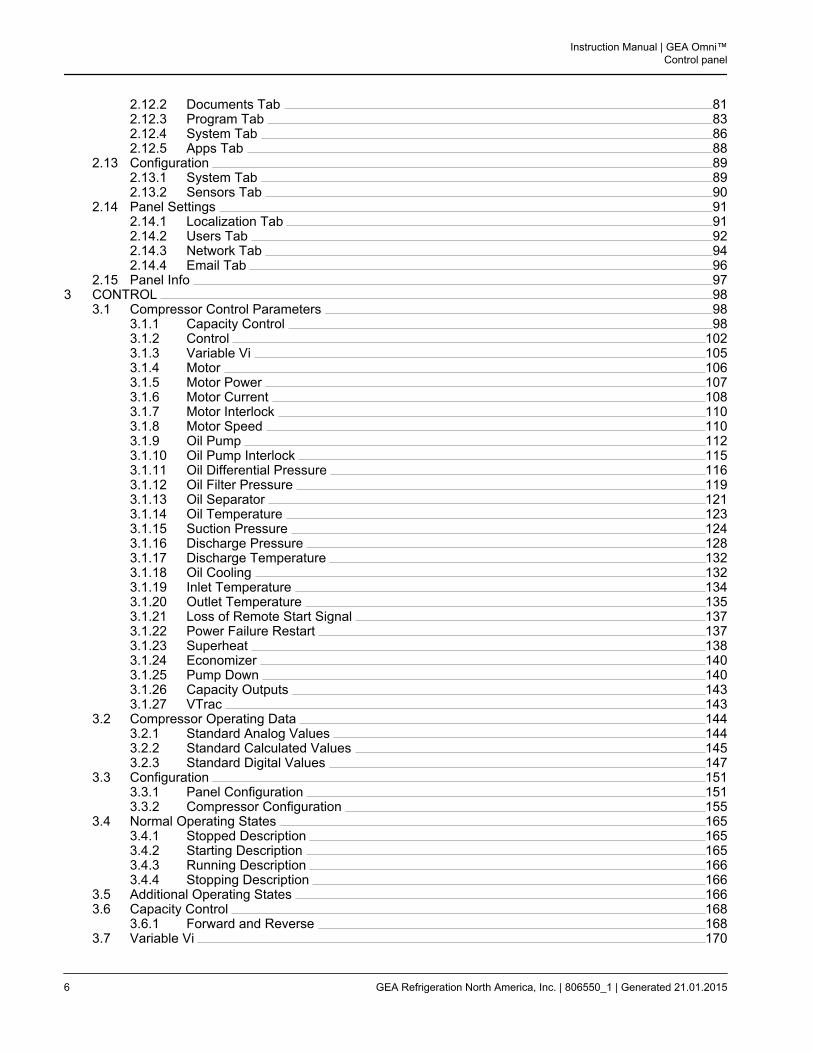
2.12.2 Documents Tab 812.12.3 Program Tab 832.12.4 System Tab 862.12.5 Apps Tab 88
2.13 Configuration 892.13.1 System Tab 892.13.2 Sensors Tab 90
2.14 Panel Settings 912.14.1 Localization Tab 912.14.2 Users Tab 922.14.3 Network Tab 942.14.4 Email Tab 96
2.15 Panel Info 973 CONTROL 98
3.1 Compressor Control Parameters 983.1.1 Capacity Control 983.1.2 Control 1023.1.3 Variable Vi 1053.1.4 Motor 1063.1.5 Motor Power 1073.1.6 Motor Current 1083.1.7 Motor Interlock 1103.1.8 Motor Speed 1103.1.9 Oil Pump 1123.1.10 Oil Pump Interlock 1153.1.11 Oil Differential Pressure 1163.1.12 Oil Filter Pressure 1193.1.13 Oil Separator 1213.1.14 Oil Temperature 1233.1.15 Suction Pressure 1243.1.16 Discharge Pressure 1283.1.17 Discharge Temperature 1323.1.18 Oil Cooling 1323.1.19 Inlet Temperature 1343.1.20 Outlet Temperature 1353.1.21 Loss of Remote Start Signal 1373.1.22 Power Failure Restart 1373.1.23 Superheat 1383.1.24 Economizer 1403.1.25 Pump Down 1403.1.26 Capacity Outputs 1433.1.27 VTrac 143
3.2 Compressor Operating Data 1443.2.1 Standard Analog Values 1443.2.2 Standard Calculated Values 1453.2.3 Standard Digital Values 147
3.3 Configuration 1513.3.1 Panel Configuration 1513.3.2 Compressor Configuration 155
3.4 Normal Operating States 1653.4.1 Stopped Description 1653.4.2 Starting Description 1653.4.3 Running Description 1663.4.4 Stopping Description 166
3.5 Additional Operating States 1663.6 Capacity Control 168
3.6.1 Forward and Reverse 1683.7 Variable Vi 170
Instruction Manual | GEA Omni™Control panel
6 GEA Refrigeration North America, Inc. | 806550_1 | Generated 21.01.2015
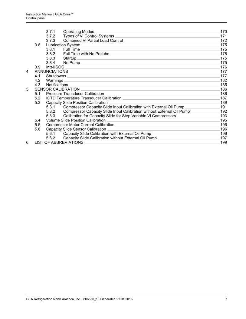
3.7.1 Operating Modes 1703.7.2 Types of Vi Control Systems 1713.7.3 Combined Vi Partial Load Control 172
3.8 Lubrication System 1753.8.1 Full Time 1753.8.2 Full Time with No Prelube 1753.8.3 Startup 1753.8.4 No Pump 175
3.9 IntelliSOC 1764 ANNUNCIATIONS 177
4.1 Shutdowns 1774.2 Warnings 1824.3 Notifications 185
5 SENSOR CALIBRATION 1865.1 Pressure Transducer Calibration 1865.2 ICTD Temperature Transducer Calibration 1875.3 Capacity Slide Position Calibration 189
5.3.1 Compressor Capacity Slide Input Calibration with External Oil Pump 1915.3.2 Compressor Capacity Slide Input Calibration without External Oil Pump 1925.3.3 Calibration for Capacity Slide for Step Variable Vi Compressors 193
5.4 Volume Slide Position Calibration 1955.5 Compressor Motor Current Calibration 1965.6 Capacity Slide Sensor Calibration 196
5.6.1 Capacity Slide Calibration with External Oil Pump 1965.6.2 Capacity Slide Calibration without External Oil Pump 197
6 LIST OF ABBREVIATIONS 199
Instruction Manual | GEA Omni™Control panel
GEA Refrigeration North America, Inc. | 806550_1 | Generated 21.01.2015 7

Instruction Manual | GEA Omni™Control panel
8 GEA Refrigeration North America, Inc. | 806550_1 | Generated 21.01.2015
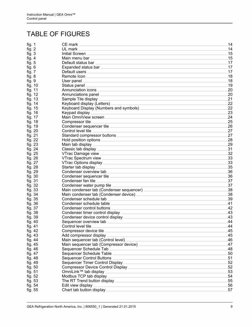
TABLE OF FIGURESfig. 1 CE mark 14fig. 2 UL mark 14fig. 3 Initial Screen 15fig. 4 Main menu bar 15fig. 5 Default status bar 17fig. 6 Expanded status bar 17fig. 7 Default users 17fig. 8 Remote Icon 18fig. 9 User panel 18fig. 10 Status panel 19fig. 11 Annunciation icons 20fig. 12 Annunciations panel 20fig. 13 Sample Tile display 21fig. 14 Keyboard display (Letters) 22fig. 15 Keyboard Display (Numbers and symbols) 22fig. 16 Keypad display 23fig. 17 Main OmniView screen 24fig. 18 Compressor tile 25fig. 19 Condenser sequencer tile 26fig. 20 Control level tile 27fig. 21 Standard compressor buttons 27fig. 22 Hold position options 28fig. 23 Main tab display 29fig. 24 Classic tab display 31fig. 25 VTrac Damage view 32fig. 26 VTrac Spectrum view 33fig. 27 VTrac Options display 33fig. 28 Starter tab display 35fig. 29 Condenser overview tab 36fig. 30 Condenser sequencer tile 36fig. 31 Condenser fan tile 37fig. 32 Condenser water pump tile 37fig. 33 Main condenser tab (Condenser sequencer) 38fig. 34 Main condenser tab (Condenser device) 38fig. 35 Condenser schedule tab 39fig. 36 Condenser schedule table 41fig. 37 Condenser control buttons 42fig. 38 Condenser timer control display 43fig. 39 Condenser device control display 43fig. 40 Sequencer overview tab 44fig. 41 Control level tile 44fig. 42 Compressor device tile 45fig. 43 Add compressor display 45fig. 44 Main sequencer tab (Control level) 46fig. 45 Main sequencer tab (Compressor device) 47fig. 46 Sequencer Schedule Tab 48fig. 47 Sequencer Schedule Table 50fig. 48 Sequencer Control Buttons 51fig. 49 Sequencer Timer Control Display 52fig. 50 Compressor Device Control Display 52fig. 51 OmniLink™ tab display 53fig. 52 Modbus TCP tab display 54fig. 53 The RT Trend button display 55fig. 54 Edit view display 56fig. 55 Chart tab button display 57
Instruction Manual | GEA Omni™Control panel
GEA Refrigeration North America, Inc. | 806550_1 | Generated 21.01.2015 9
fig. 56 RT-Trend tab display (View - Graph) 58fig. 57 RT-Trend tab display (View - Table) 58fig. 58 Chart tab display (View - Graph) 59fig. 59 Chart tab display (View - Table) 59fig. 60 Annunciations tab display 60fig. 61 Analysis tab display 62fig. 62 Reporting tab display 63fig. 63 Documents tile display 64fig. 64 Sample document display 65fig. 65 Videos tile display 66fig. 66 Sample video display 66fig. 67 I/O Status tab display 67fig. 68 Sample digital input slice display 68fig. 69 Sample digital output slice display 68fig. 70 Compressor motor start notification 68fig. 71 Sample analog input slice display 69fig. 72 Sample analog output slice display 69fig. 73 Maintenance tab display 70fig. 74 Service task form display 71fig. 75 Edit service tasks display 72fig. 76 Service maintenance display 73fig. 77 Activity log tab display 74fig. 78 Touch panel tab display 76fig. 79 Wash down icon 76fig. 80 Logic diagram tab display 77fig. 81 Support files tab display 78fig. 82 Documents tab display 81fig. 83 Program tab display 83fig. 84 Update/Back up software display 84fig. 85 Update/Back up configuration display 85fig. 86 System tab display 86fig. 87 Update/Back up system display 87fig. 88 Factory default files display 87fig. 89 Apps tab display 88fig. 90 System tab display 89fig. 91 Sensors tab display 90fig. 92 Localization tab display 91fig. 93 Users tab display 92fig. 94 Network tab display 94fig. 95 Email tab display 96fig. 96 Panel info tab display 97fig. 97 Estimated power demand , calculation formula 108fig. 98 Project details options 151fig. 99 Panel details options 153fig. 100 Package details options 155fig. 101 Oil system details options 159fig. 102 Motor options 161fig. 103 Remote Set Point Options 163fig. 104 Suction options 163fig. 105 Discharge options 164fig. 106 Economizer details options 164fig. 107 Forward acting capacity control 169fig. 108 Reverse acting capacity control 170fig. 109 Pressure Sensor Calibration Pad 186fig. 110 Temperature Probe Calibration Pad 187fig. 111 Capacity Slide Calibration Pad 189fig. 112 Capacity Slide Calibration Pad (Step Variable Vi) 193fig. 113 Volume Slide Calibration Pad 195
Instruction Manual | GEA Omni™Control panel
10 GEA Refrigeration North America, Inc. | 806550_1 | Generated 21.01.2015
fig. 114 Motor Current Calibration Pad 196
Instruction Manual | GEA Omni™Control panel
GEA Refrigeration North America, Inc. | 806550_1 | Generated 21.01.2015 11

Instruction Manual | GEA Omni™Control panel
12 GEA Refrigeration North America, Inc. | 806550_1 | Generated 21.01.2015
1 SAFETY AND CONFORMITY
1.1 Safety Instructions
The GEA Omni™ is reliable in operation if used as specified.
Hint!
Read the safety instructions in the GEA Omni™ operating manual before startup.
The intended use includes the observance and compliance of the following:
• all notices regarding hazard to persons and damage to property in the operating instructions,
• the country-specific standards and safety regulations,
• the instruction for installation, operation and maintenance,
• the details of certificates,
• the requirements for personnel,
• the obligation to exercise due care.Only compliance with all provisions and guidelines will enable optimum protection of the personnel as well asdangers to the environment and the safe and smooth operation of the GEA Omni™.
Warning!
GEA Omni™ can cause hazard in case of improper or unintended use. A malfunction indica-tion on the touch screen cannot be ignored.A personal injury or damage to the machine or plant can be the result.For precautions to prevent danger see safety instructions in the operating manual.
Warning of electric shock!Danger of electric shock exists.More than one switch-disconnect may be necessary to isolate all electrical components.Before maintenance work on the control panel, make sure that all electrical components areswitched off.
1.2 Safety note concerning the connection of the GEA Omni™ with the starter panel
Hint!
It is not permitted to add an external controller between the GEA Omni™ and the power panel;this would compromise the safety interlocks designed for protecting personnel and equip-ment. All control signals between the GEA Omni™ and the starter panel must be processeddirectly and must not flow indirectly via an external controller. GEA Refrigeration North Amer-ica, Inc. cannot otherwise guarantee the safe operation of the system.
Instruction Manual | GEA Omni™Control panel
Safety and ConformitySafety Instructions
GEA Refrigeration North America, Inc. | 806550_1 | Generated 21.01.2015 13
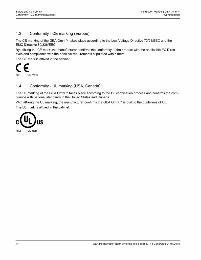
1.3 Conformity - CE marking (Europe)
The CE marking of the GEA Omni™ takes place according to the Low Voltage Directive 73/23/EEC and theEMC Directive 89/336/EEC.By affixing the CE mark, the manufacturer confirms the conformity of the product with the applicable EC Direc-tives and compliance with the principle requirements stipulated within them.The CE mark is affixed in the cabinet.
fig.1: CE mark
1.4 Conformity - UL marking (USA, Canada)
The UL marking of the GEA Omni™ takes place according to the UL certification process and confirms the com-pliance with national standards in the United States and Canada.With affixing the UL marking, the manufacturer confirms the GEA Omni™ is built to the guidelines of UL.The UL mark is affixed in the cabinet.
fig.2: UL mark
Safety and ConformityConformity - CE marking (Europe)
Instruction Manual | GEA Omni™Control panel
14 GEA Refrigeration North America, Inc. | 806550_1 | Generated 21.01.2015
2 USER INTERFACE
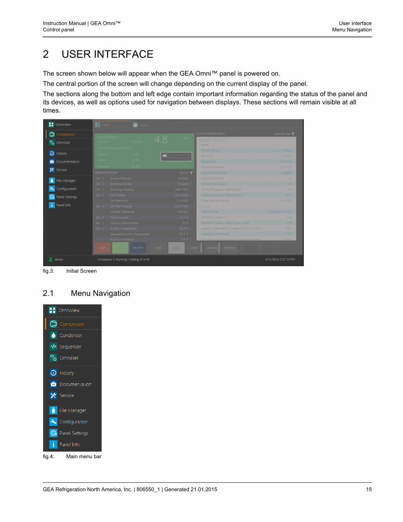
The screen shown below will appear when the GEA Omni™ panel is powered on.The central portion of the screen will change depending on the current display of the panel.The sections along the bottom and left edge contain important information regarding the status of the panel andits devices, as well as options used for navigation between displays. These sections will remain visible at alltimes.
fig.3: Initial Screen
2.1 Menu Navigation
fig.4: Main menu bar
Instruction Manual | GEA Omni™Control panel
User interfaceMenu Navigation
GEA Refrigeration North America, Inc. | 806550_1 | Generated 21.01.2015 15
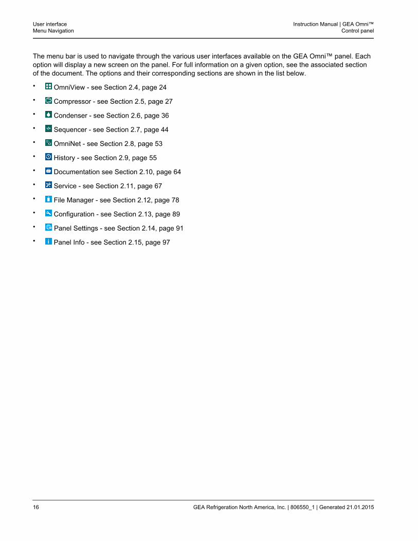
The menu bar is used to navigate through the various user interfaces available on the GEA Omni™ panel. Eachoption will display a new screen on the panel. For full information on a given option, see the associated sectionof the document. The options and their corresponding sections are shown in the list below.
• OmniView - see Section 2.4, page 24
• Compressor - see Section 2.5, page 27
• Condenser - see Section 2.6, page 36
• Sequencer - see Section 2.7, page 44
• OmniNet - see Section 2.8, page 53
• History - see Section 2.9, page 55
• Documentation see Section 2.10, page 64
• Service - see Section 2.11, page 67
• File Manager - see Section 2.12, page 78
• Configuration - see Section 2.13, page 89
• Panel Settings - see Section 2.14, page 91
• Panel Info - see Section 2.15, page 97
User interfaceMenu Navigation
Instruction Manual | GEA Omni™Control panel
16 GEA Refrigeration North America, Inc. | 806550_1 | Generated 21.01.2015
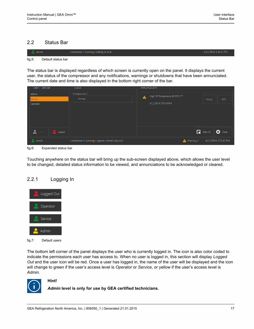
2.2 Status Bar
fig.5: Default status bar
The status bar is displayed regardless of which screen is currently open on the panel. It displays the currentuser, the status of the compressor and any notifications, warnings or shutdowns that have been annunciated.The current date and time is also displayed in the bottom right corner of the bar.
fig.6: Expanded status bar
Touching anywhere on the status bar will bring up the sub-screen displayed above, which allows the user levelto be changed, detailed status information to be viewed, and annunciations to be acknowledged or cleared.
2.2.1 Logging In
fig.7: Default users
The bottom left corner of the panel displays the user who is currently logged in. The icon is also color coded toindicate the permissions each user has access to. When no user is logged in, this section will display LoggedOut and the user icon will be red. Once a user has logged in, the name of the user will be displayed and the iconwill change to green if the user’s access level is Operator or Service, or yellow if the user’s access level isAdmin.
Hint!
Admin level is only for use by GEA certified technicians.
Instruction Manual | GEA Omni™Control panel
User interfaceStatus Bar
GEA Refrigeration North America, Inc. | 806550_1 | Generated 21.01.2015 17

fig.8: Remote Icon
Additionally, if the panel is currently being viewed remotely through OmniLink, the bottom left hand corner of thedisplay will blink back and forth between the icon for the current user and the remote icon shown above. Theremote icon is always colored blue and displays how many remote devices are currently viewing the panel dis-play.
fig.9: User panel
The section shown to the far left of the sub-screen when the status bar is clicked displays a list of all users cur-rently associated with the panel. For more information on adding or deleting users, refer to Section 2.14.2,page 92.If the user selected in the list is the one that is currently logged in, the Logout button will be enabled, which willcause the panel to display the Logged Out message until another user is logged in. The Login button will beenabled whenever a user account other than the one that is currently logged in is selected.When a user not currently signed in is selected, the Login button will be enabled. Touching it will bring up anumeric keypad which will allow the user to enter their password. If the correct password is entered, the selecteduser will be signed in on the panel. If another user is already logged in, logging in as a different user will result inthem being signed out.
The default passwords for the Operator, Service and Admin access levels are displayed in the table shown tothe below. It is advisable to change these passwords once startup is completed.
Access level Default password
Operator 1
Service 123654
Admin 1236547890
User interfaceStatus Bar
Instruction Manual | GEA Omni™Control panel
18 GEA Refrigeration North America, Inc. | 806550_1 | Generated 21.01.2015
Hint!
The Admin account will only be accessible on new panels if a USB containing the AdminAccess Key file is plugged into the panel. In this case, the Admin password does not need tobe entered.The Admin account will also be accessible for Retrofit panels and panels sold without a pack-age or skid. In this case, the user will need to enter the Admin password displayed above. Theaccount will remain enabled until the panel is commissioned.
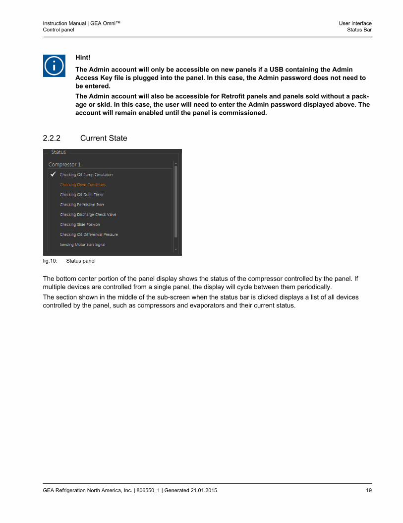
2.2.2 Current State
fig.10: Status panel
The bottom center portion of the panel display shows the status of the compressor controlled by the panel. Ifmultiple devices are controlled from a single panel, the display will cycle between them periodically.The section shown in the middle of the sub-screen when the status bar is clicked displays a list of all devicescontrolled by the panel, such as compressors and evaporators and their current status.
Instruction Manual | GEA Omni™Control panel
User interfaceStatus Bar
GEA Refrigeration North America, Inc. | 806550_1 | Generated 21.01.2015 19
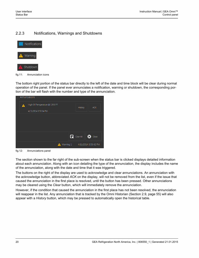
2.2.3 Notifications, Warnings and Shutdowns
fig.11: Annunciation icons
The bottom right portion of the status bar directly to the left of the date and time block will be clear during normaloperation of the panel. If the panel ever annunciates a notification, warning or shutdown, the corresponding por-tion of the bar will flash with the number and type of the annunciation.
fig.12: Annunciations panel
The section shown to the far right of the sub-screen when the status bar is clicked displays detailed informationabout each annunciation. Along with an icon detailing the type of the annunciation, the display includes the nameof the annunciation, along with the date and time that it was triggered.The buttons on the right of the display are used to acknowledge and clear annunciations. An annunciation withthe acknowledge button, abbreviated ACK on the display, will not be removed from the list, even if the issue thatcaused the annunciation in the first place is resolved, until the button has been pressed. Other annunciationsmay be cleared using the Clear button, which will immediately remove the annunciation.However, if the condition that caused the annunciation in the first place has not been resolved, the annunciationwill reappear in the list. Any annunciation that is tracked by the Omni Historian (Section 2.9, page 55) will alsoappear with a History button, which may be pressed to automatically open the historical table.
User interfaceStatus Bar
Instruction Manual | GEA Omni™Control panel
20 GEA Refrigeration North America, Inc. | 806550_1 | Generated 21.01.2015
2.3 General Navigation
The user interface (UI) for the GEA Omni™ makes use of a number of different navigation methods. The follow-ing is a brief description of each of these methods.
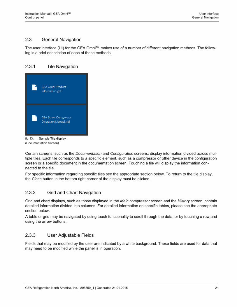
2.3.1 Tile Navigation
fig.13: Sample Tile display(Documentation Screen)
Certain screens, such as the Documentation and Configuration screens, display information divided across mul-tiple tiles. Each tile corresponds to a specific element, such as a compressor or other device in the configurationscreen or a specific document in the documentation screen. Touching a tile will display the information con-nected to the tile.For specific information regarding specific tiles see the appropriate section below. To return to the tile display,the Close button in the bottom right corner of the display must be clicked.
2.3.2 Grid and Chart Navigation
Grid and chart displays, such as those displayed in the Main compressor screen and the History screen, containdetailed information divided into columns. For detailed information on specific tables, please see the appropriatesection below.A table or grid may be navigated by using touch functionality to scroll through the data, or by touching a row andusing the arrow buttons.
2.3.3 User Adjustable Fields
Fields that may be modified by the user are indicated by a white background. These fields are used for data thatmay need to be modified while the panel is in operation.
Instruction Manual | GEA Omni™Control panel
User interfaceGeneral Navigation
GEA Refrigeration North America, Inc. | 806550_1 | Generated 21.01.2015 21
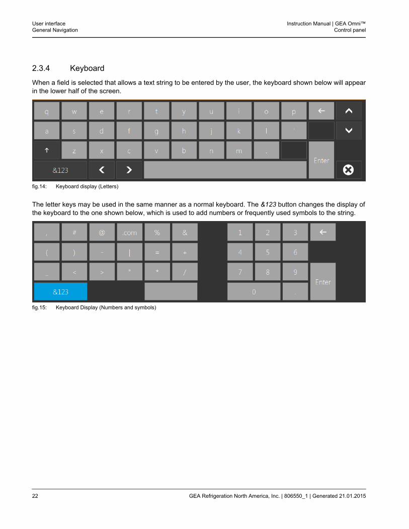
2.3.4 Keyboard
When a field is selected that allows a text string to be entered by the user, the keyboard shown below will appearin the lower half of the screen.
fig.14: Keyboard display (Letters)
The letter keys may be used in the same manner as a normal keyboard. The &123 button changes the display ofthe keyboard to the one shown below, which is used to add numbers or frequently used symbols to the string.
fig.15: Keyboard Display (Numbers and symbols)
User interfaceGeneral Navigation
Instruction Manual | GEA Omni™Control panel
22 GEA Refrigeration North America, Inc. | 806550_1 | Generated 21.01.2015
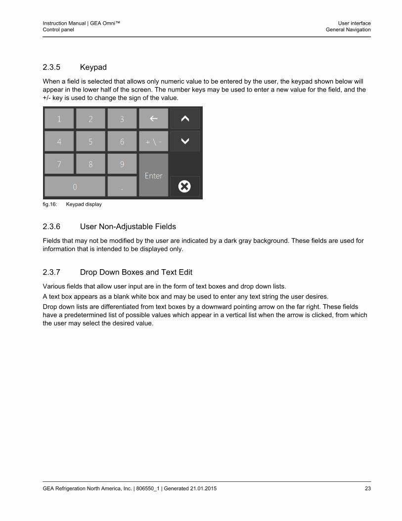
2.3.5 Keypad
When a field is selected that allows only numeric value to be entered by the user, the keypad shown below willappear in the lower half of the screen. The number keys may be used to enter a new value for the field, and the+/- key is used to change the sign of the value.
fig.16: Keypad display
2.3.6 User Non-Adjustable Fields
Fields that may not be modified by the user are indicated by a dark gray background. These fields are used forinformation that is intended to be displayed only.
2.3.7 Drop Down Boxes and Text Edit
Various fields that allow user input are in the form of text boxes and drop down lists.A text box appears as a blank white box and may be used to enter any text string the user desires.Drop down lists are differentiated from text boxes by a downward pointing arrow on the far right. These fieldshave a predetermined list of possible values which appear in a vertical list when the arrow is clicked, from whichthe user may select the desired value.
Instruction Manual | GEA Omni™Control panel
User interfaceGeneral Navigation
GEA Refrigeration North America, Inc. | 806550_1 | Generated 21.01.2015 23
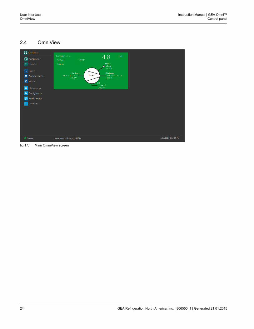
2.4 OmniView
fig.17: Main OmniView screen
User interfaceOmniView
Instruction Manual | GEA Omni™Control panel
24 GEA Refrigeration North America, Inc. | 806550_1 | Generated 21.01.2015
2.4.1 Main Viewing Application
The main OmniView screen will display tiles corresponding to each device controlled by the panel. Each tile dis-plays the name and pertinent information for the associated device.
Standard Devices
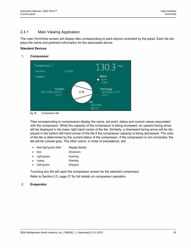
1. Compressor
fig.18: Compressor tile
Tiles corresponding to compressors display the name, set point, status and current values associatedwith the compressor. While the capacity of the compressor is being increased, an upward facing arrowwill be displayed in the lower right hand corner of the tile. Similarly, a downward facing arrow will be dis-played in the bottom left hand corner of the tile if the compressor capacity is being decreased. The colorof the tile is determined by the current status of the compressor. If the compressor is not connected, thetile will be colored gray. The other colors, in order of precedence, are:
Touching any tile will open the compressor screen for the selected compressor.Refer to Section 2.5, page 27 for full details on compressor operation.
2. Evaporator
Instruction Manual | GEA Omni™Control panel
User interfaceOmniView
GEA Refrigeration North America, Inc. | 806550_1 | Generated 21.01.2015 25
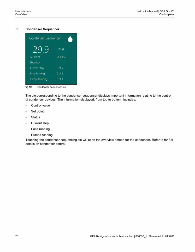
3. Condenser Sequencer
fig.19: Condenser sequencer tile
The tile corresponding to the condenser sequencer displays important information relating to the controlof condenser devices. The information displayed, from top to bottom, includes:
– Control value
– Set point
– Status
– Current step
– Fans running
– Pumps runningTouching the condenser sequencing tile will open the overview screen for the condenser. Refer to for fulldetails on condenser control.
User interfaceOmniView
Instruction Manual | GEA Omni™Control panel
26 GEA Refrigeration North America, Inc. | 806550_1 | Generated 21.01.2015
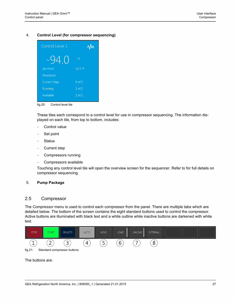
4. Control Level (for compressor sequencing)
fig.20: Control level tile
These tiles each correspond to a control level for use in compressor sequencing. The information dis-played on each tile, from top to bottom, includes:
– Control value
– Set point
– Status
– Current step
– Compressors running
– Compressors availableTouching any control level tile will open the overview screen for the sequencer. Refer to for full details oncompressor sequencing.
5. Pump Package
2.5 Compressor
The Compressor menu is used to control each compressor from the panel. There are multiple tabs which aredetailed below. The bottom of the screen contains the eight standard buttons used to control the compressor.Active buttons are illuminated with black text and a white outline while inactive buttons are darkened with whitetext.
fig.21: Standard compressor buttons
The buttons are:
Instruction Manual | GEA Omni™Control panel
User interfaceCompressor
GEA Refrigeration North America, Inc. | 806550_1 | Generated 21.01.2015 27
1. STOPThis button is illuminated whenever the compressor is in the stopped state, whether through a normalstoppage or through a shutdown condition. Touching this button will initiate the stopping procedure. Formore information, refer to Section 3.4.4, page 166. Touching the button a second time will cause thecompressor to stop without unloading.
2. STARTThis button is illuminated whenever the compressor is running in local mode. Touching this button willattempt to start the compressor. If the compressor is in the process of starting, this button will flash.Once the compressor has started, the button will be illuminated continuously. If the compressor is inAutomatic Start/Stop mode, this button will display an A in its upper left hand corner and will resumeflashing if it has been automatically stopped to allow pressure to build.
3. REMOTEThis button is illuminated whenever the compressor is set to receive instructions from an externalsource, such as a sequencer. Touching this button will switch the compressor from local to remote con-trol.
4. AUTOThis button is illuminated whenever the compressor is set to control its capacity automatically based onthe control signal. Touching the button will switch the compressor to Automatic mode.
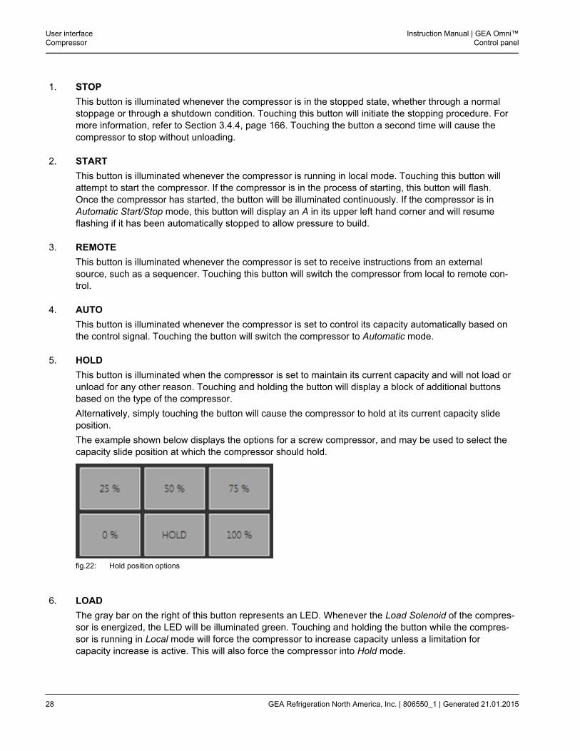
5. HOLDThis button is illuminated when the compressor is set to maintain its current capacity and will not load orunload for any other reason. Touching and holding the button will display a block of additional buttonsbased on the type of the compressor.Alternatively, simply touching the button will cause the compressor to hold at its current capacity slideposition.The example shown below displays the options for a screw compressor, and may be used to select thecapacity slide position at which the compressor should hold.
fig.22: Hold position options
6. LOADThe gray bar on the right of this button represents an LED. Whenever the Load Solenoid of the compres-sor is energized, the LED will be illuminated green. Touching and holding the button while the compres-sor is running in Local mode will force the compressor to increase capacity unless a limitation forcapacity increase is active. This will also force the compressor into Hold mode.
User interfaceCompressor
Instruction Manual | GEA Omni™Control panel
28 GEA Refrigeration North America, Inc. | 806550_1 | Generated 21.01.2015
7. UNLOADThe gray bar on the right of this button represents an LED. Whenever the Unload Solenoid of the com-pressor is energized, the LED will be illuminated green. Touching and holding the button while the com-pressor is running in Local mode will force the compressor to decrease capacity unless a limitation forcapacity decrease is active. This will also force the compressor into Hold mode.
8. EXTERNALThis button will be illuminated when the capacity of the compressor is being controlled remotely from anexternal device. Touching the button will force the compressor’s capacity mode into External mode.
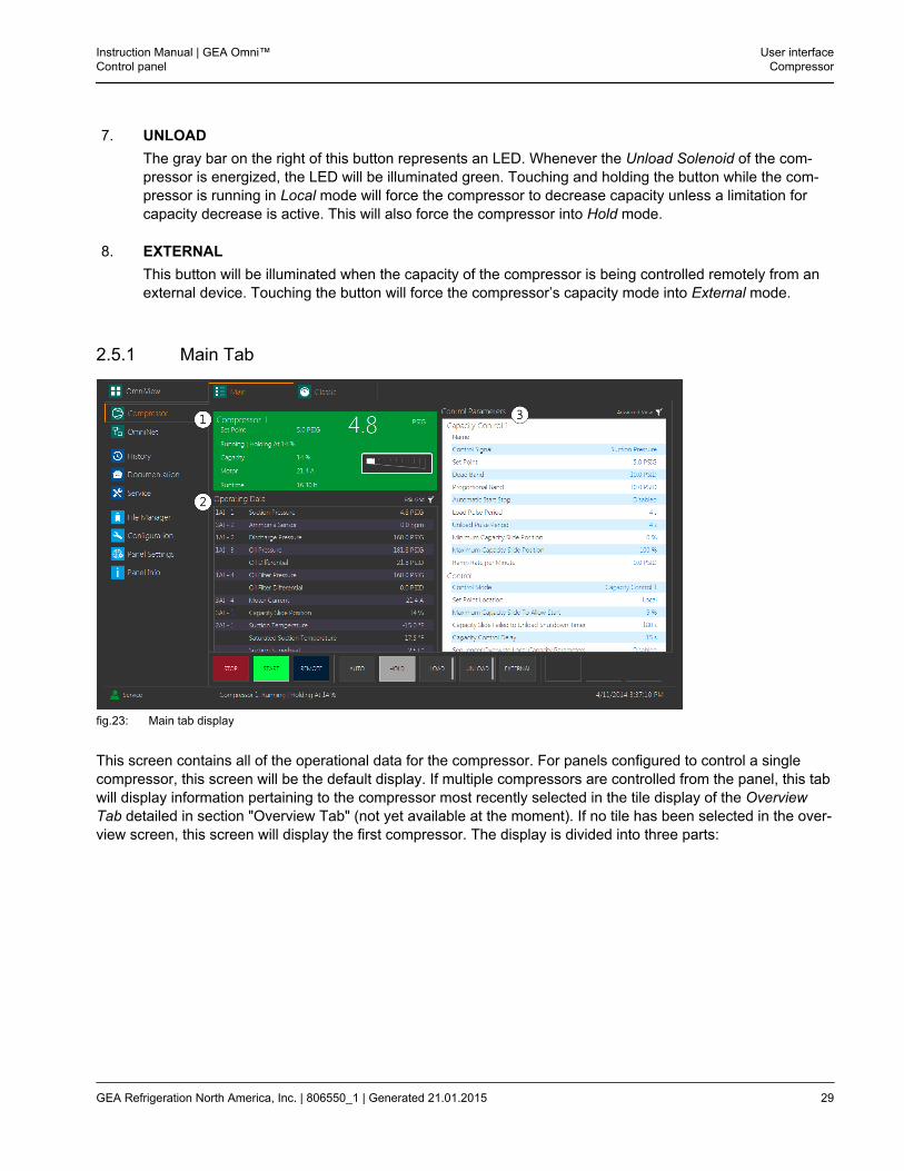
2.5.1 Main Tab
fig.23: Main tab display
This screen contains all of the operational data for the compressor. For panels configured to control a singlecompressor, this screen will be the default display. If multiple compressors are controlled from the panel, this tabwill display information pertaining to the compressor most recently selected in the tile display of the OverviewTab detailed in section "Overview Tab" (not yet available at the moment). If no tile has been selected in the over-view screen, this screen will display the first compressor. The display is divided into three parts:
Instruction Manual | GEA Omni™Control panel
User interfaceCompressor
GEA Refrigeration North America, Inc. | 806550_1 | Generated 21.01.2015 29
1. Main Compressor DisplayThis portion of the screen displays the current status of the compressor. The color of the display isdependent on the status of the compressor. The colors, in order of precedance, are:
2. Operating DataThis table contains the current values associated with the compressor.The information in the table is divided into three columns. The left column contains the slice location ofthe value, if applicable. If the row in question does not correspond to a slice location, this column will beblank. The middle column contains the name of the variable. The right column contains the current valueand units of the variable, if applicable.The Edit Grid button in the upper right corner of the table will display a fourth column containing checkboxes which allows the user to toggle which rows are displayed. A checked row is displayed, while anunchecked row is hidden. While the check boxes are displayed, the text of the Edit Grid button willchange to Save Grid. Touching the button a second time will hide the fourth column and display onlyselected rows.Each user may customize the values displayed in this table separately.For details on individual elements of the Operating Data display, refer to Section 3.2, page 144.
3. Control ParametersThis table contains the name and current values of the parameters used to control the compressor.Each parameter may be edited by touching the row and either selecting an option from a list of possibili-ties,or entering a new value using the keypad or keyboard. The color of the text indicates whether thevalue may be edited; blue values may be modified, gray values may not. For normal operation, only theparameters that may be edited by the user are displayed.Touching the Advanced View button will instead display all parameter data. This will also change the textof the button to Basic View, which may be clicked a second time to only display the editable parameterdata. For details on individual control parameters, refer to Section 3.1, page 98.
User interfaceCompressor
Instruction Manual | GEA Omni™Control panel
30 GEA Refrigeration North America, Inc. | 806550_1 | Generated 21.01.2015
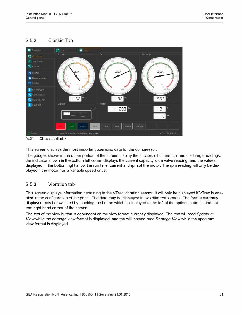
2.5.2 Classic Tab
fig.24: Classic tab display
This screen displays the most important operating data for the compressor.The gauges shown in the upper portion of the screen display the suction, oil differential and discharge readings,the indicator shown in the bottom left corner displays the current capacity slide valve reading, and the valuesdisplayed in the bottom right show the run time, current and rpm of the motor. The rpm reading will only be dis-played if the motor has a variable speed drive.
2.5.3 Vibration tab
This screen displays information pertaining to the VTrac vibration sensor. It will only be displayed if VTrac is ena-bled in the configuration of the panel. The data may be displayed in two different formats. The format currentlydisplayed may be switched by touching the button which is displayed to the left of the options button in the bot-tom right hand corner of the screen.The text of the view button is dependent on the view format currently displayed. The text will read SpectrumView while the damage view format is displayed, and the will instead read Damage View while the spectrumview format is displayed.
Instruction Manual | GEA Omni™Control panel
User interfaceCompressor
GEA Refrigeration North America, Inc. | 806550_1 | Generated 21.01.2015 31
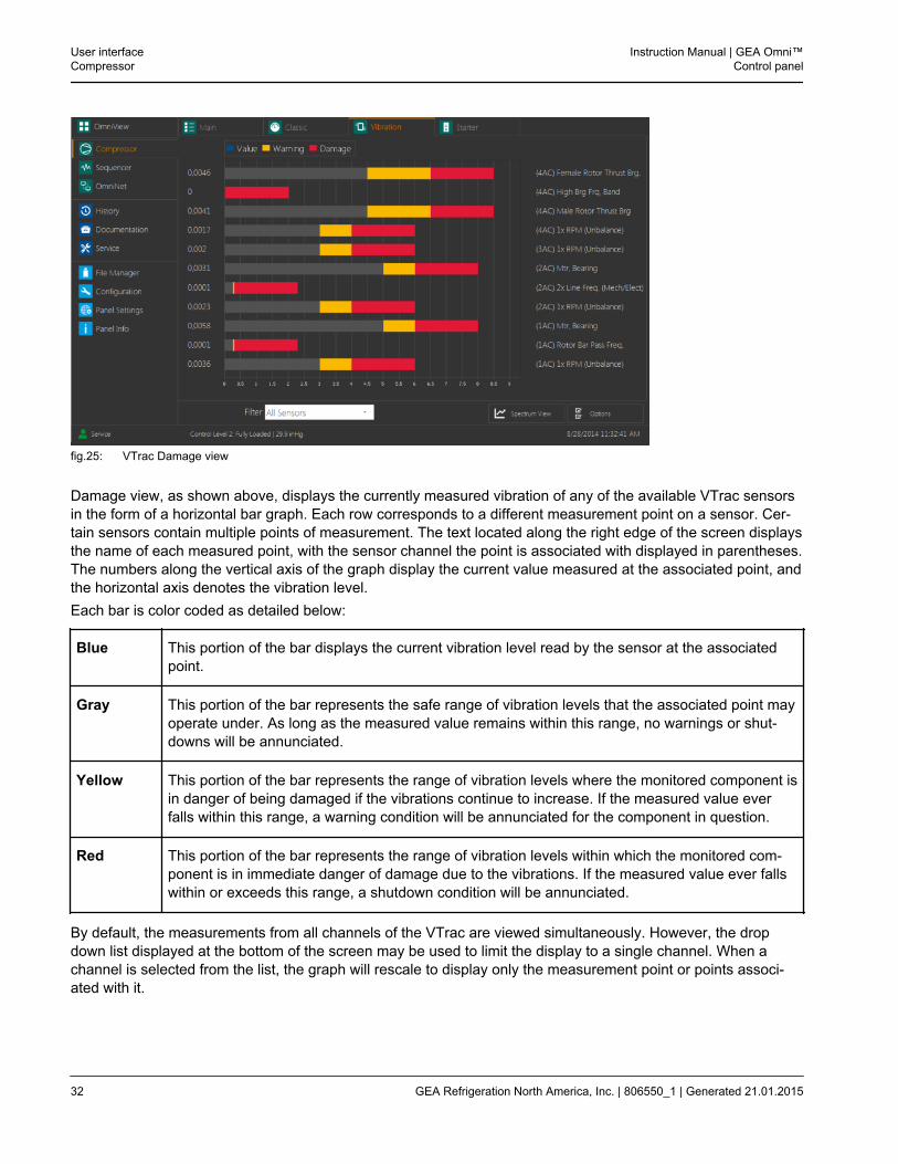
fig.25: VTrac Damage view
Damage view, as shown above, displays the currently measured vibration of any of the available VTrac sensorsin the form of a horizontal bar graph. Each row corresponds to a different measurement point on a sensor. Cer-tain sensors contain multiple points of measurement. The text located along the right edge of the screen displaysthe name of each measured point, with the sensor channel the point is associated with displayed in parentheses.The numbers along the vertical axis of the graph display the current value measured at the associated point, andthe horizontal axis denotes the vibration level.Each bar is color coded as detailed below:
Blue This portion of the bar displays the current vibration level read by the sensor at the associatedpoint.
Gray This portion of the bar represents the safe range of vibration levels that the associated point mayoperate under. As long as the measured value remains within this range, no warnings or shut-downs will be annunciated.
Yellow This portion of the bar represents the range of vibration levels where the monitored component isin danger of being damaged if the vibrations continue to increase. If the measured value everfalls within this range, a warning condition will be annunciated for the component in question.
Red This portion of the bar represents the range of vibration levels within which the monitored com-ponent is in immediate danger of damage due to the vibrations. If the measured value ever fallswithin or exceeds this range, a shutdown condition will be annunciated.
By default, the measurements from all channels of the VTrac are viewed simultaneously. However, the dropdown list displayed at the bottom of the screen may be used to limit the display to a single channel. When achannel is selected from the list, the graph will rescale to display only the measurement point or points associ-ated with it.
User interfaceCompressor
Instruction Manual | GEA Omni™Control panel
32 GEA Refrigeration North America, Inc. | 806550_1 | Generated 21.01.2015
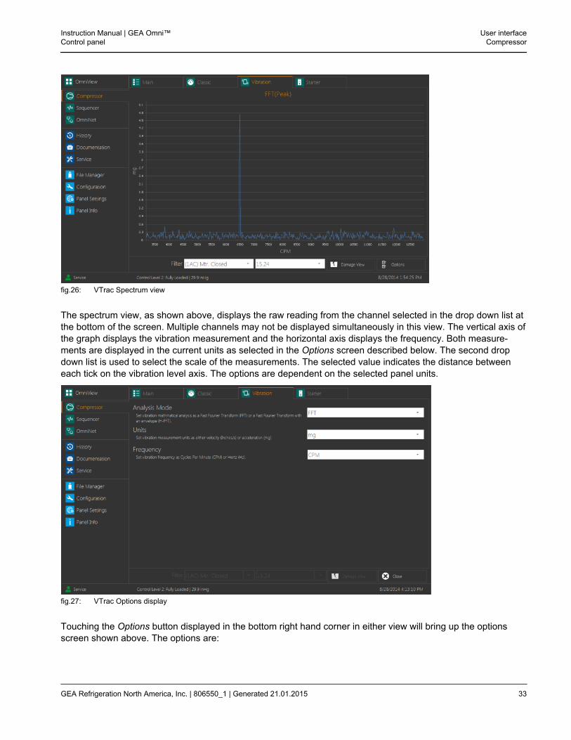
fig.26: VTrac Spectrum view
The spectrum view, as shown above, displays the raw reading from the channel selected in the drop down list atthe bottom of the screen. Multiple channels may not be displayed simultaneously in this view. The vertical axis ofthe graph displays the vibration measurement and the horizontal axis displays the frequency. Both measure-ments are displayed in the current units as selected in the Options screen described below. The second dropdown list is used to select the scale of the measurements. The selected value indicates the distance betweeneach tick on the vibration level axis. The options are dependent on the selected panel units.
fig.27: VTrac Options display
Touching the Options button displayed in the bottom right hand corner in either view will bring up the optionsscreen shown above. The options are:
Instruction Manual | GEA Omni™Control panel
User interfaceCompressor
GEA Refrigeration North America, Inc. | 806550_1 | Generated 21.01.2015 33
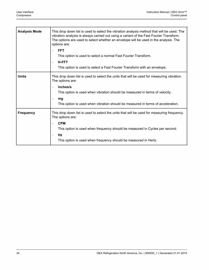
Analysis Mode This drop down list is used to select the vibration analysis method that will be used. Thevibration analysis is always carried out using a variant of the Fast Fourier Transform.The options are used to select whether an envelope will be used in the analysis. Theoptions are:
– FFTThis option is used to select a normal Fast Fourier Transform.
– H-FFTThis option is used to select a Fast Fourier Transform with an envelope.
Units This drop down list is used to select the units that will be used for measuring vibration.The options are:
– inches/sThis option is used when vibration should be measured in terms of velocity.
– mgThis option is used when vibration should be measured in terms of acceleration.
Frequency This drop down list is used to select the units that will be used for measuring frequency.The options are:
– CPMThis option is used when frequency should be measured in Cycles per second.
– HzThis option is used when frequency should be measured in Hertz.
User interfaceCompressor
Instruction Manual | GEA Omni™Control panel
34 GEA Refrigeration North America, Inc. | 806550_1 | Generated 21.01.2015
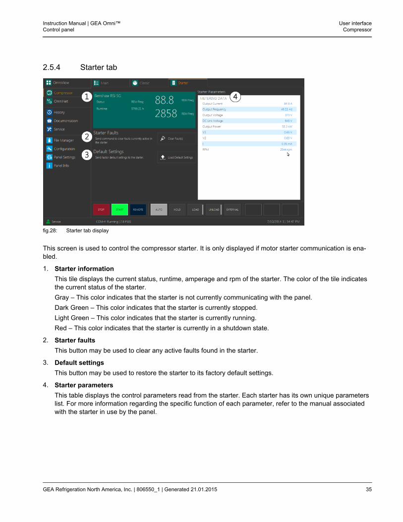
2.5.4 Starter tab
fig.28: Starter tab display
This screen is used to control the compressor starter. It is only displayed if motor starter communication is ena-bled.
1. Starter informationThis tile displays the current status, runtime, amperage and rpm of the starter. The color of the tile indicatesthe current status of the starter.Gray – This color indicates that the starter is not currently communicating with the panel.Dark Green – This color indicates that the starter is currently stopped.Light Green – This color indicates that the starter is currently running.Red – This color indicates that the starter is currently in a shutdown state.
2. Starter faultsThis button may be used to clear any active faults found in the starter.
3. Default settingsThis button may be used to restore the starter to its factory default settings.
4. Starter parametersThis table displays the control parameters read from the starter. Each starter has its own unique parameterslist. For more information regarding the specific function of each parameter, refer to the manual associatedwith the starter in use by the panel.
Instruction Manual | GEA Omni™Control panel
User interfaceCompressor
GEA Refrigeration North America, Inc. | 806550_1 | Generated 21.01.2015 35
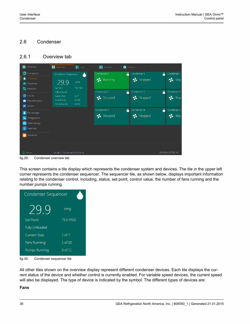
2.6 Condenser
2.6.1 Overview tab
fig.29: Condenser overview tab
This screen contains a tile display which represents the condenser system and devices. The tile in the upper leftcorner represents the condenser sequencer. The sequencer tile, as shown below, displays important informationrelating to the condenser control, including, status, set point, control value, the number of fans running and thenumber pumps running.
fig.30: Condenser sequencer tile
All other tiles shown on the overview display represent different condenser devices. Each tile displays the cur-rent status of the device and whether control is currently enabled. For variable speed devices, the current speedwill also be displayed. The type of device is indicated by the symbol. The different types of devices are:
Fans
User interfaceCondenser
Instruction Manual | GEA Omni™Control panel
36 GEA Refrigeration North America, Inc. | 806550_1 | Generated 21.01.2015
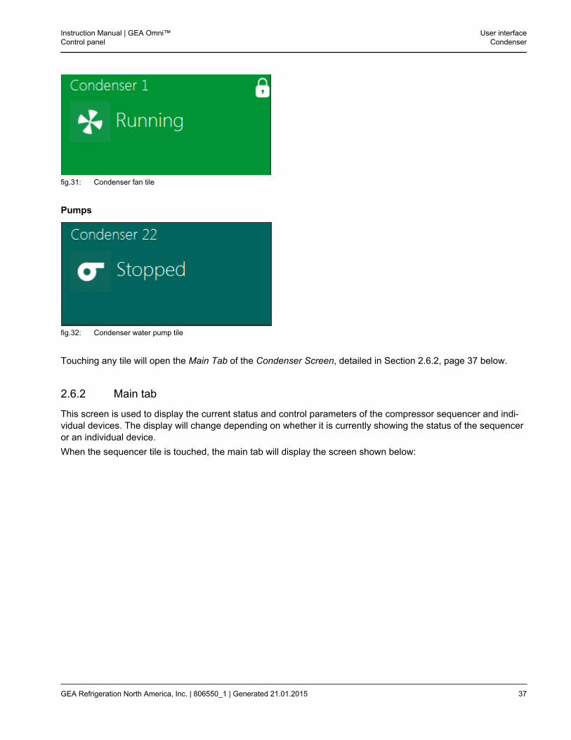
fig.31: Condenser fan tile
Pumps
fig.32: Condenser water pump tile
Touching any tile will open the Main Tab of the Condenser Screen, detailed in Section 2.6.2, page 37 below.
2.6.2 Main tab
This screen is used to display the current status and control parameters of the compressor sequencer and indi-vidual devices. The display will change depending on whether it is currently showing the status of the sequenceror an individual device.When the sequencer tile is touched, the main tab will display the screen shown below:
Instruction Manual | GEA Omni™Control panel
User interfaceCondenser
GEA Refrigeration North America, Inc. | 806550_1 | Generated 21.01.2015 37
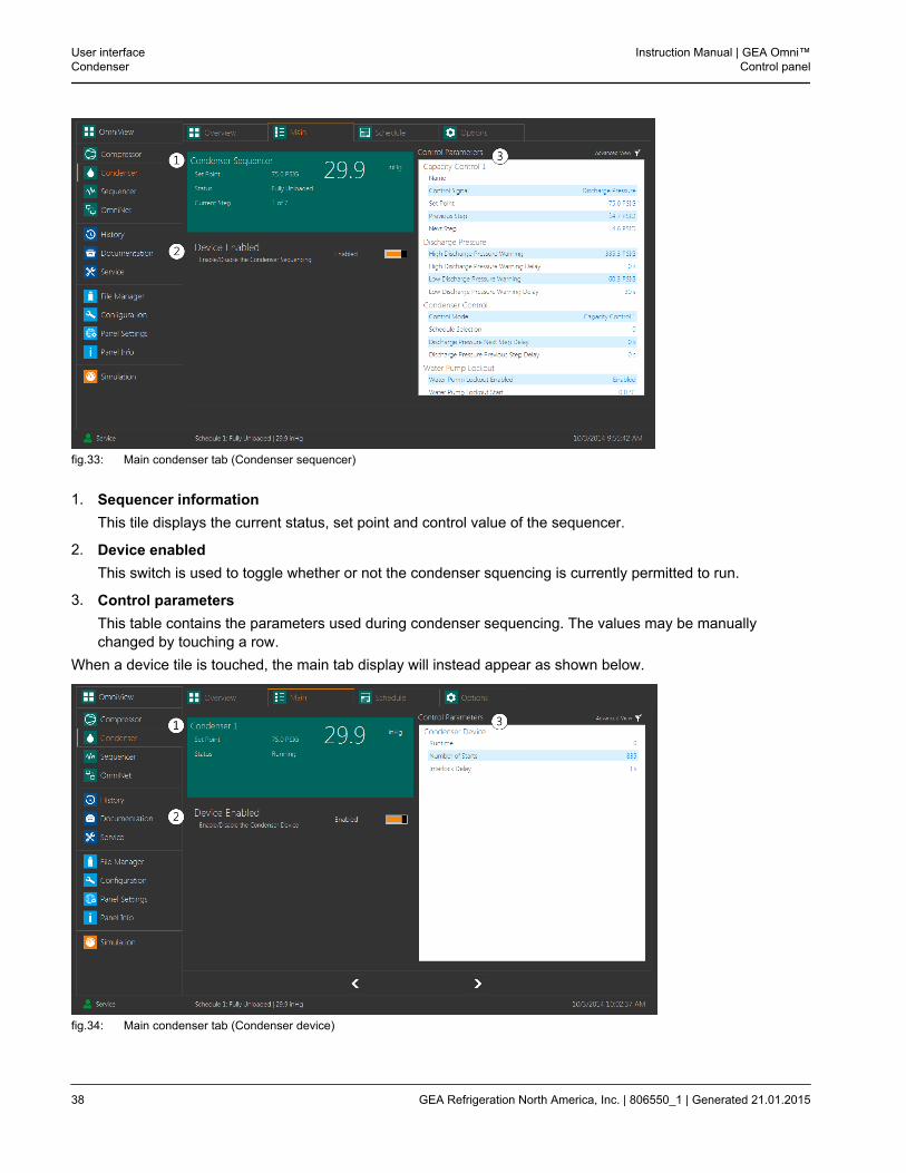
fig.33: Main condenser tab (Condenser sequencer)
1. Sequencer informationThis tile displays the current status, set point and control value of the sequencer.
2. Device enabledThis switch is used to toggle whether or not the condenser squencing is currently permitted to run.
3. Control parametersThis table contains the parameters used during condenser sequencing. The values may be manuallychanged by touching a row.
When a device tile is touched, the main tab display will instead appear as shown below.
fig.34: Main condenser tab (Condenser device)
User interfaceCondenser
Instruction Manual | GEA Omni™Control panel
38 GEA Refrigeration North America, Inc. | 806550_1 | Generated 21.01.2015
1. Device informationThis tile displays the name, current status, set point and control value of the selected device. The currentspeed will also be displayed here for variable speed devices.
2. Device enabledThis switch is used to toggle whether or not the device is currently permitted to run.
3. Control parametersThis table contains parameters containing basic information regarding the selected condenser. The valuesmay be manually changed by touching a row.
Touching the Main tab displayed at the top of the screen will bring up the display corresponding to the mostrecently selected tile. If no tile has been previously selected in the Overview tab, the panel will bring up the infor-mation of the condenser sequencer by default.
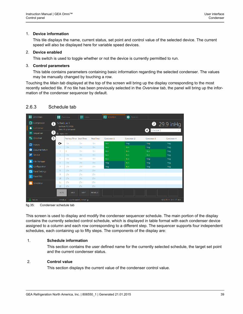
2.6.3 Schedule tab
fig.35: Condenser schedule tab
This screen is used to display and modify the condenser sequencer schedule. The main portion of the displaycontains the currently selected control schedule, which is displayed in table format with each condenser deviceassigned to a column and each row corresponding to a different step. The sequencer supports four independentschedules, each containing up to fifty steps. The components of the display are:
1. Schedule informationThis section contains the user defined name for the currently selected schedule, the target set pointand the current condenser status.
2. Control valueThis section displays the current value of the condenser control value.
Instruction Manual | GEA Omni™Control panel
User interfaceCondenser
GEA Refrigeration North America, Inc. | 806550_1 | Generated 21.01.2015 39
3. Hide/ show timersThis button controls whether or not the three initial columns of the schedule table, containing thetime delays used while the sequencer is running automatically, are displayed.
4. Schedule selectionThis drop down list is used to select which schedule is currently displayed.
User interfaceCondenser
Instruction Manual | GEA Omni™Control panel
40 GEA Refrigeration North America, Inc. | 806550_1 | Generated 21.01.2015
5. Schedule tableThis table displays all steps that will be executed by the condenser sequencer during normal paneloperation.
fig.36: Condenser schedule table
a. Current stepThis icon indicates which step is currently being executed by the sequencer.
b. Previous timerThis column contains the period of time that the sequencer will wait before changing steps onceit has been instructed to switch to the previous step. This column will not appear if the HideTimers button has been clicked.
c. Soak timerThis column contains the period of time that the sequencer must remain on the current stepbefore determining if it should step ahead to the next step, step back to the previous step, orremain on the current step. This column will not appear if the Hide Timers button has beenclicked.
d. Next timerThis column contains the period of time that the sequencer will wait before changing steps onceit has been instructed to switch to the next step. This column will not appear if the Hide Timersbutton has been clicked.
e. Condenser devicesThese columns each correspond to an individual condenser device. The contents of each celldictate what action the device will take during the associated step. The options are:
– RunThis option is available for single speed fans and pumps. It will cause the device to activateduring the associated step.
– StopThis option is available for all devices. It will cause the device to deactivate during the asso-ciated step.
– Hold
Instruction Manual | GEA Omni™Control panel
User interfaceCondenser
GEA Refrigeration North America, Inc. | 806550_1 | Generated 21.01.2015 41
This option is only available for variable speed devices. Whenever it is selected, the devicewill continue to run at its current speed during the associated step.
– AutoThis option is only available for variable speed devices. Whenever it is selected, a percent-age value may be entered, corresponding to a percent of the device’s maximum speed. Thedevice adjusts its speed automatically to match the chosen value and continue to makeadjustments to maintain the chosen value during the associated step.
6. Control buttons
fig.37: Condenser control buttons
These buttons are used to control the sequencer. The buttons are:
a. AutoAs long as this button is illuminated, the sequencer will run automatically based on the valuesentered in the three timer columns.
b. HoldAs long as this button is illuminated, the sequencer will remain on the currently selected step.
c. NextWhen this button is touched, the sequencer will immediately switch from the current step to thenext step below it in the table. If the sequencer is already on the final step, touching this buttonwill have no effect.
d. PreviousWhen this button is touched, the sequencer will immediately switch from the current step to theprevious step above it in the table. If the sequencer is already on the first step, touching thisbutton will have no effect.
The values in the table display may be modified by touching the appropriate cell of the table. When-ever a cell containing a time is touched, the sub-window below will be displayed.
User interfaceCondenser
Instruction Manual | GEA Omni™Control panel
42 GEA Refrigeration North America, Inc. | 806550_1 | Generated 21.01.2015
fig.38: Condenser timer control display
The value of the timer may be changed with the number pad, and the units may be changed withthe drop down list in the middle. If the Apply to all Timers box is checked, any change made to onetimer will affect all timers in the same column. The arrow keys may be used to navigate through thetable.Whenever a cell in a condenser device column is touched, the sub window will instead appear asshown below:
fig.39: Condenser device control display
The state the condenser should enter in the given step may be selected in the central options block.For certain options which require a percentage of the maximum capacity to be specified, the secondoptions block will be enabled. A percentage between 0% and 100 %, incremented in values of 5%,may be selected from this list.
Instruction Manual | GEA Omni™Control panel
User interfaceCondenser
GEA Refrigeration North America, Inc. | 806550_1 | Generated 21.01.2015 43
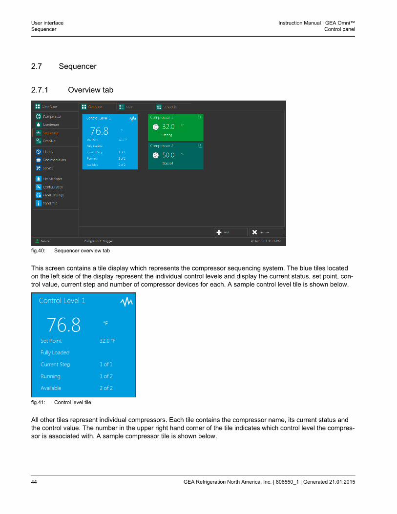
2.7 Sequencer
2.7.1 Overview tab
fig.40: Sequencer overview tab
This screen contains a tile display which represents the compressor sequencing system. The blue tiles locatedon the left side of the display represent the individual control levels and display the current status, set point, con-trol value, current step and number of compressor devices for each. A sample control level tile is shown below.
fig.41: Control level tile
All other tiles represent individual compressors. Each tile contains the compressor name, its current status andthe control value. The number in the upper right hand corner of the tile indicates which control level the compres-sor is associated with. A sample compressor tile is shown below.
User interfaceSequencer
Instruction Manual | GEA Omni™Control panel
44 GEA Refrigeration North America, Inc. | 806550_1 | Generated 21.01.2015
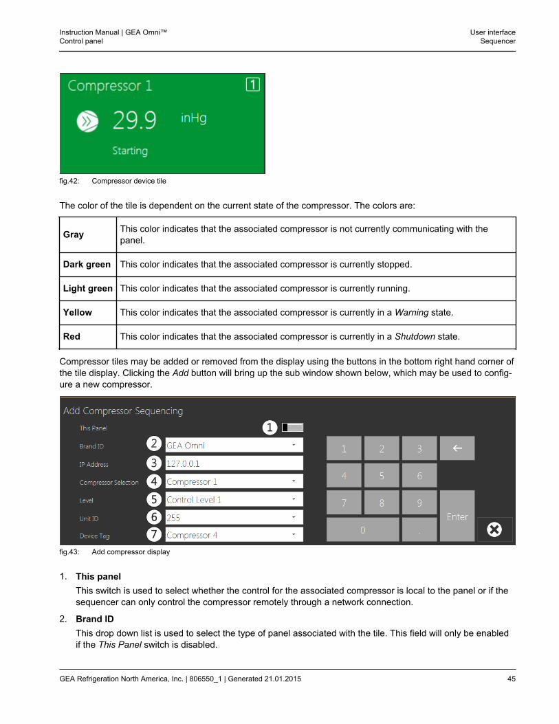
fig.42: Compressor device tile
The color of the tile is dependent on the current state of the compressor. The colors are:
Gray This color indicates that the associated compressor is not currently communicating with thepanel.
Dark green This color indicates that the associated compressor is currently stopped.
Light green This color indicates that the associated compressor is currently running.
Yellow This color indicates that the associated compressor is currently in a Warning state.
Red This color indicates that the associated compressor is currently in a Shutdown state.
Compressor tiles may be added or removed from the display using the buttons in the bottom right hand corner ofthe tile display. Clicking the Add button will bring up the sub window shown below, which may be used to config-ure a new compressor.
fig.43: Add compressor display
1. This panelThis switch is used to select whether the control for the associated compressor is local to the panel or if thesequencer can only control the compressor remotely through a network connection.
2. Brand IDThis drop down list is used to select the type of panel associated with the tile. This field will only be enabledif the This Panel switch is disabled.
Instruction Manual | GEA Omni™Control panel
User interfaceSequencer
GEA Refrigeration North America, Inc. | 806550_1 | Generated 21.01.2015 45
3. IP addressThis text box is used to enter the network location where the local panel controlling the compressor may befound. This field will only be enabled if the This Panel switch is disabled.
4. Compressor selectionThis drop down list is used to select the number of the compressor. The options are dependent on the typeof panel affiliated with the compressor.
5. LevelThis drop down list is used to select which of the available control levels the compressor will be sequencedon. Any level that is currently enabled will appear in the options.
6. Unit IDThis drop down list is used to select the Modbus ID of the panel. This option will only be used if thesequencer utilizes an Ethernet to Serial communication convertor.
7. Device tagThis drop down list is used to select the name that will be associated with the compressor.
Clicking any tile will open the main tab for the compressor sequencer as detailed in Section 2.7.2, page 46.
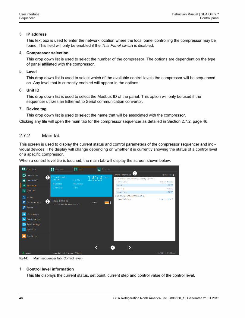
2.7.2 Main tab
This screen is used to display the current status and control parameters of the compressor sequencer and indi-vidual devices. The display will change depending on whether it is currently showing the status of a control levelor a specific compressor.When a control level tile is touched, the main tab will display the screen shown below:
fig.44: Main sequencer tab (Control level)
1. Control level informationThis tile displays the current status, set point, current step and control value of the control level.
User interfaceSequencer
Instruction Manual | GEA Omni™Control panel
46 GEA Refrigeration North America, Inc. | 806550_1 | Generated 21.01.2015
2. Level enabledThis switch is used to toggle whether or not compressors on the selected level are currently permitted to besequenced.
3. Control ParametersThis table contains the parameters used during compressor sequencing. The values may be manuallychanged by touching a row.
4. Arrow ButtonsThese buttons may be used to navigate between the displays for each control level.
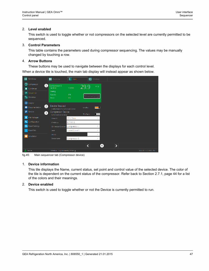
When a device tile is touched, the main tab display will instead appear as shown below.
fig.45: Main sequencer tab (Compressor device)
1. Device informationThis tile displays the Name, current status, set point and control value of the selected device. The color ofthe tile is dependent on the current status of the compressor. Refer back to Section 2.7.1, page 44 for a listof the colors and their meanings.
2. Device enabledThis switch is used to toggle whether or not the Device is currently permitted to run.
Instruction Manual | GEA Omni™Control panel
User interfaceSequencer
GEA Refrigeration North America, Inc. | 806550_1 | Generated 21.01.2015 47
3. Compressor deviceThis section contains the information that was entered when the compressor in question was added to theoverview display. Refer back to Section 2.7.1, page 44 for the functions of each field. The fields are:
• This panel
• Brand ID
• IP address
• Compressor selection
• Level
• Unit ID
• Device Name
4. Arrow buttonsThese buttons may be used to navigate between all compressor devices.
Touching the Main tab displayed at the top of the screen will bring up the display corresponding to the mostrecently selected tile. If no tile has been previously selected in the Overview tab, the panel will bring up the infor-mation of the compressor sequencer by default.
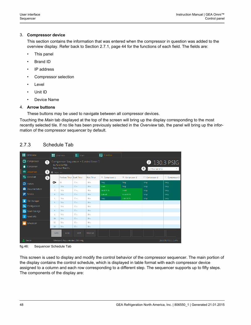
2.7.3 Schedule Tab
fig.46: Sequencer Schedule Tab
This screen is used to display and modify the control behavior of the compressor sequencer. The main portion ofthe display contains the control schedule, which is displayed in table format with each compressor deviceassigned to a column and each row corresponding to a different step. The sequencer supports up to fifty steps.The components of the display are:
User interfaceSequencer
Instruction Manual | GEA Omni™Control panel
48 GEA Refrigeration North America, Inc. | 806550_1 | Generated 21.01.2015
1. Current LevelThis section contains the user defined name for the currently selected level, the target set point andthe current level status.
2. Control valueThis section displays the current control value of the level.
3. Hide/ show timersThis button controls whether or not the three initial columns of the schedule table, containing thetime delays used while the sequencer is running automatically, are displayed.
4. Level SelectionThis drop down list is used to select which level is currently displayed.
Instruction Manual | GEA Omni™Control panel
User interfaceSequencer
GEA Refrigeration North America, Inc. | 806550_1 | Generated 21.01.2015 49
5. Schedule tableThis table displays all steps that will be executed by the compressor sequencer on the currentlyselected level during normal panel operation.
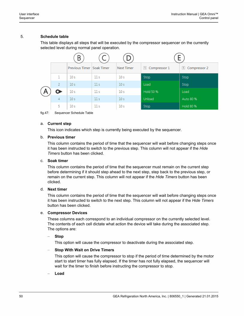
fig.47: Sequencer Schedule Table
a. Current stepThis icon indicates which step is currently being executed by the sequencer.
b. Previous timerThis column contains the period of time that the sequencer will wait before changing steps onceit has been instructed to switch to the previous step. This column will not appear if the HideTimers button has been clicked.
c. Soak timerThis column contains the period of time that the sequencer must remain on the current stepbefore determining if it should step ahead to the next step, step back to the previous step, orremain on the current step. This column will not appear if the Hide Timers button has beenclicked.
d. Next timerThis column contains the period of time that the sequencer will wait before changing steps onceit has been instructed to switch to the next step. This column will not appear if the Hide Timersbutton has been clicked.
e. Compressor DevicesThese columns each correspond to an individual compressor on the currently selected level.The contents of each cell dictate what action the device will take during the associated step.The options are:
– StopThis option will cause the compressor to deactivate during the associated step.
– Stop With Wait on Drive TimersThis option will cause the compressor to stop if the period of time determined by the motorstart to start timer has fully elapsed. If the timer has not fully elapsed, the sequencer willwait for the timer to finish before instructing the compressor to stop.
– Load
User interfaceSequencer
Instruction Manual | GEA Omni™Control panel
50 GEA Refrigeration North America, Inc. | 806550_1 | Generated 21.01.2015

This option will cause the compressor to increase its capacity during the associated step.
– UnloadThis option will cause the compressor to decrease its capacity during the associated step.
– AutoThis option will cause the compressor to automatically take steps to maintain a specific per-cent capacity. The compressor will automatically load or unload to maintain the chosenvalue during the associated step.
– HoldThis option will cause the compressor to remain at a selected capacity during the associ-ated step.
– StandbyThis option will cause the compressor to monitor all other compressors on the same level. Ifany monitored compressor enters a shutdown state or cannot be started remotely, the com-pressor will start. If multiple compressors are in standby mode at the same time, the com-pressor that is most similar to the failed or inaccessible compressor will start.
6. Control buttons
fig.48: Sequencer Control Buttons
These buttons are used to control the operating mode sequencer. The buttons are:
a. AutoAs long as this button is illuminated, the sequencer will run automatically based on the valuesentered in the three timer columns.
b. HoldAs long as this button is illuminated, the sequencer will remain on the currently selected step.
c. NextWhen this button is touched, the sequencer will immediately switch from the current step to thenext step below it in the table. If the sequencer is already on the final step, touching this buttonwill have no effect.
d. PreviousWhen this button is touched, the sequencer will immediately switch from the current step to theprevious step above it in the table. If the sequencer is already on the first step, touching thisbutton will have no effect.
Instruction Manual | GEA Omni™Control panel
User interfaceSequencer
GEA Refrigeration North America, Inc. | 806550_1 | Generated 21.01.2015 51
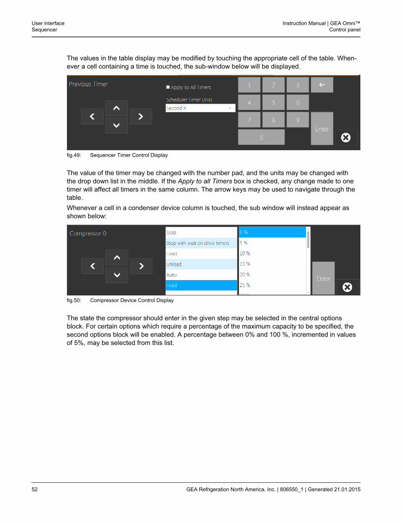
The values in the table display may be modified by touching the appropriate cell of the table. When-ever a cell containing a time is touched, the sub-window below will be displayed.
fig.49: Sequencer Timer Control Display
The value of the timer may be changed with the number pad, and the units may be changed withthe drop down list in the middle. If the Apply to all Timers box is checked, any change made to onetimer will affect all timers in the same column. The arrow keys may be used to navigate through thetable.Whenever a cell in a condenser device column is touched, the sub window will instead appear asshown below:
fig.50: Compressor Device Control Display
The state the compressor should enter in the given step may be selected in the central optionsblock. For certain options which require a percentage of the maximum capacity to be specified, thesecond options block will be enabled. A percentage between 0% and 100 %, incremented in valuesof 5%, may be selected from this list.
User interfaceSequencer
Instruction Manual | GEA Omni™Control panel
52 GEA Refrigeration North America, Inc. | 806550_1 | Generated 21.01.2015
2.8 OmniNet
2.8.1 OmniLink™ Tab
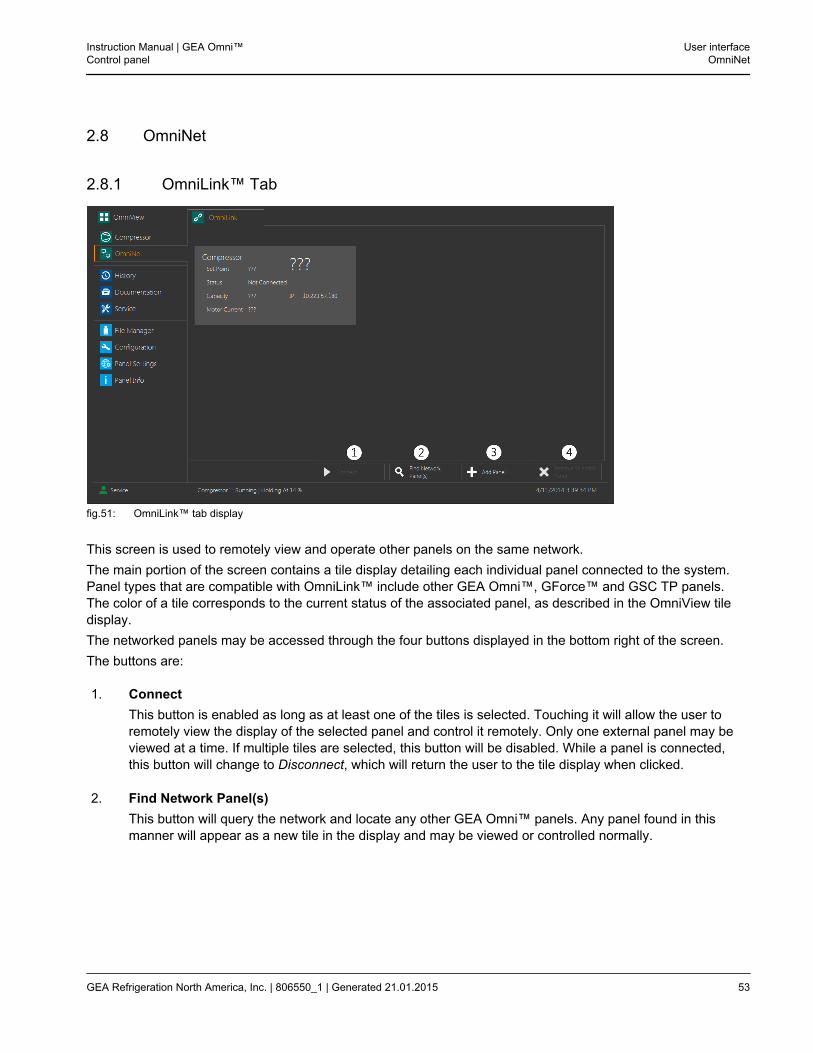
fig.51: OmniLink™ tab display
This screen is used to remotely view and operate other panels on the same network.The main portion of the screen contains a tile display detailing each individual panel connected to the system.Panel types that are compatible with OmniLink™ include other GEA Omni™, GForce™ and GSC TP panels.The color of a tile corresponds to the current status of the associated panel, as described in the OmniView tiledisplay.The networked panels may be accessed through the four buttons displayed in the bottom right of the screen.The buttons are:
1. ConnectThis button is enabled as long as at least one of the tiles is selected. Touching it will allow the user toremotely view the display of the selected panel and control it remotely. Only one external panel may beviewed at a time. If multiple tiles are selected, this button will be disabled. While a panel is connected,this button will change to Disconnect, which will return the user to the tile display when clicked.
2. Find Network Panel(s)This button will query the network and locate any other GEA Omni™ panels. Any panel found in thismanner will appear as a new tile in the display and may be viewed or controlled normally.
Instruction Manual | GEA Omni™Control panel
User interfaceOmniNet
GEA Refrigeration North America, Inc. | 806550_1 | Generated 21.01.2015 53
3. Add PanelThis button will bring up a keypad display, which will prompt the user to enter an IP address to manuallyadd a panel to the tile display.
4. Remove Selected PanelThis button is enabled as long as at least one of the tiles is selected. Touching it will remove the selectedpanel or panels from the tile display.
2.8.2 Modbus TCP Tab
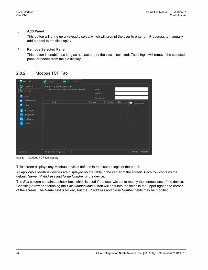
fig.52: Modbus TCP tab display
This screen displays any Modbus devices defined in the custom logic of the panel.All applicable Modbus devices are displayed on the table in the center of the screen. Each row contains thedefault Name, IP Address and Node Number of the device.The Edit column contains a check box, which is used if the user wishes to modify the connections of the device.Checking a row and touching the Edit Connections button will populate the fields in the upper right hand cornerof the screen. The Name field is locked, but the IP Address and Node Number fields may be modified.
User interfaceOmniNet
Instruction Manual | GEA Omni™Control panel
54 GEA Refrigeration North America, Inc. | 806550_1 | Generated 21.01.2015
2.9 History
The History screen is used to display operating data for the panel over time. The historical data of the panel isdivided across five tabs, as detailed in the sections below.
2.9.1 Bottom Menu Navigation
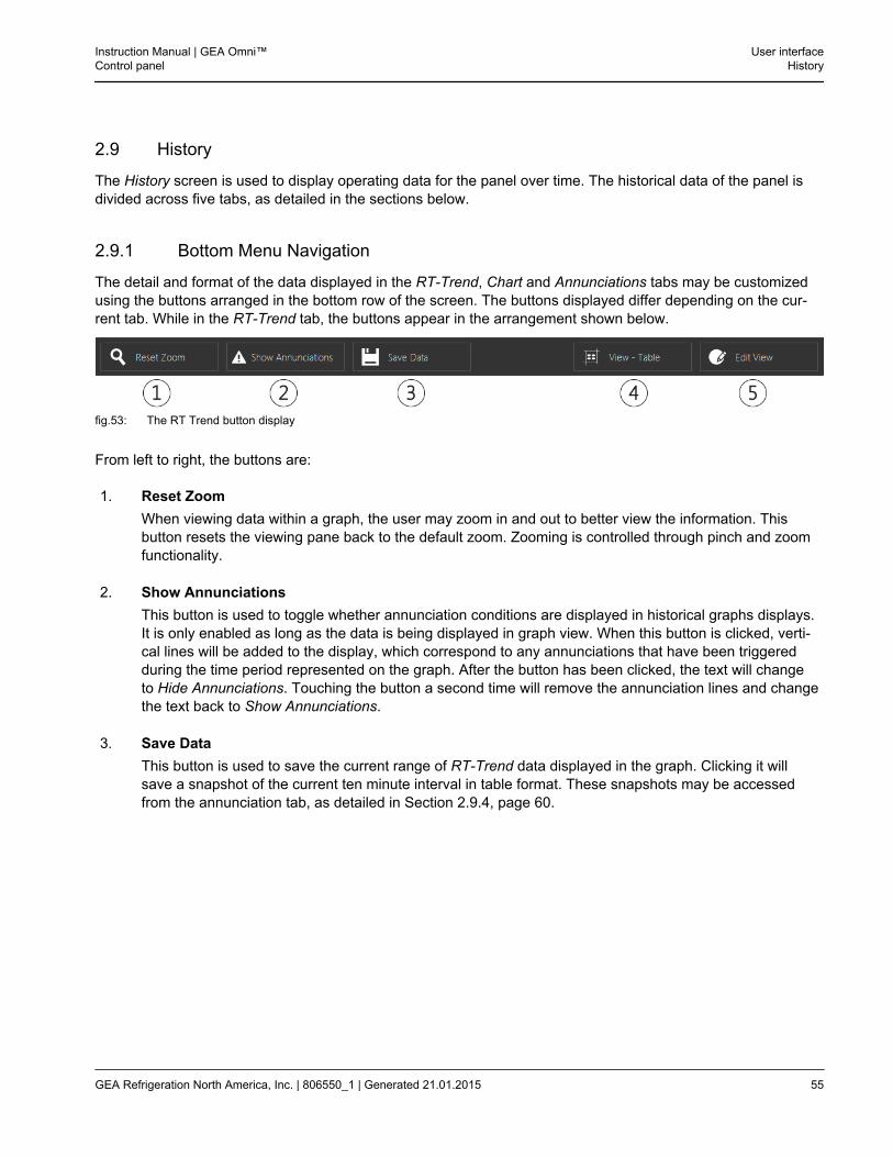
The detail and format of the data displayed in the RT-Trend, Chart and Annunciations tabs may be customizedusing the buttons arranged in the bottom row of the screen. The buttons displayed differ depending on the cur-rent tab. While in the RT-Trend tab, the buttons appear in the arrangement shown below.
fig.53: The RT Trend button display
From left to right, the buttons are:
1. Reset ZoomWhen viewing data within a graph, the user may zoom in and out to better view the information. Thisbutton resets the viewing pane back to the default zoom. Zooming is controlled through pinch and zoomfunctionality.
2. Show AnnunciationsThis button is used to toggle whether annunciation conditions are displayed in historical graphs displays.It is only enabled as long as the data is being displayed in graph view. When this button is clicked, verti-cal lines will be added to the display, which correspond to any annunciations that have been triggeredduring the time period represented on the graph. After the button has been clicked, the text will changeto Hide Annunciations. Touching the button a second time will remove the annunciation lines and changethe text back to Show Annunciations.
3. Save DataThis button is used to save the current range of RT-Trend data displayed in the graph. Clicking it willsave a snapshot of the current ten minute interval in table format. These snapshots may be accessedfrom the annunciation tab, as detailed in Section 2.9.4, page 60.
Instruction Manual | GEA Omni™Control panel
User interfaceHistory
GEA Refrigeration North America, Inc. | 806550_1 | Generated 21.01.2015 55
4. View - TableThis button is used to toggle how the historical data is displayed on screen. It is only enabled in the RT-Trend and Chart tabs. Touching the button will cause the data to be displayed in table format, with rowscorresponding to the time increments and columns corresponding to the values that are being monitored.As long as the data is displayed in table mode, the text on the button will instead read View - Graph,which will return the display to the graphical display and change the text back to View - Table whenclicked.
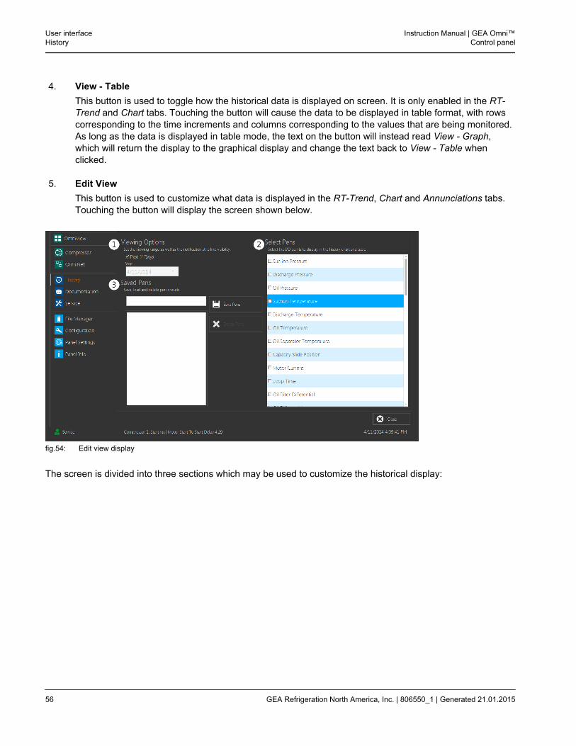
5. Edit ViewThis button is used to customize what data is displayed in the RT-Trend, Chart and Annunciations tabs.Touching the button will display the screen shown below.
fig.54: Edit view display
The screen is divided into three sections which may be used to customize the historical display:
User interfaceHistory
Instruction Manual | GEA Omni™Control panel
56 GEA Refrigeration North America, Inc. | 806550_1 | Generated 21.01.2015
1. Viewing OptionsThe panel always displays forty eight hours’ worth of historical data. By default, the check box Past 2Days is checked, which instructs the panel to display historical data from two days previous until thepresent moment. If this box is unchecked, the drop down list will become enabled and may be used toselect a custom end date, which will cause the panel to display two days’ worth of historical data endingon the selected date.Additionally, the check boxes below the drop down box are used select which, if any, annunciation typesare displayed when the user elects to display notifications on the historical graph.
2. Select PensThese check boxes are used to select which values are tracked on the RT-Trend and historical graphs.
3. Saved PensSpecific groupings of pens may be saved for easy access later through this section. Entering a groupname in the upper text field and touching the Save Pens button will add the selection of pens to the list ofpen groups shown in the lower box. If no name is entered, the selection will be saved using the currentdate and time as a name.Individual selections may be checked in the same manner as specific pens. Selections may be deletedfrom the list of saved pens by checking them and touching the Delete Pens button.
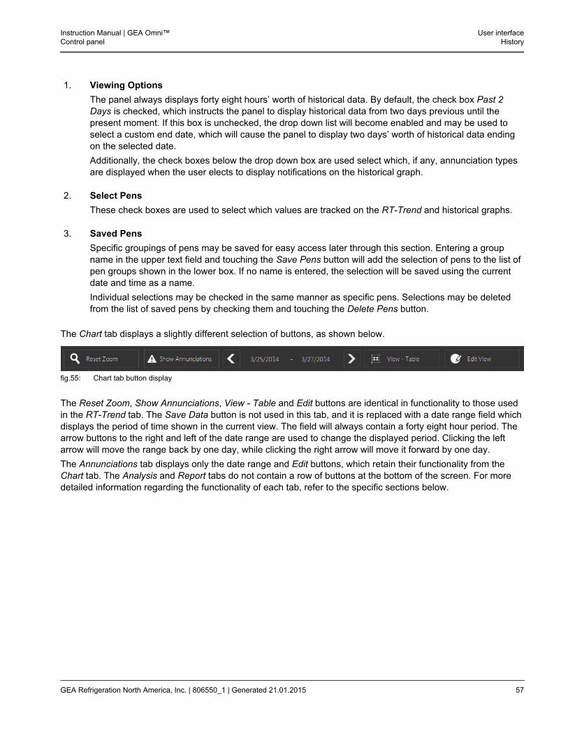
The Chart tab displays a slightly different selection of buttons, as shown below.
fig.55: Chart tab button display
The Reset Zoom, Show Annunciations, View - Table and Edit buttons are identical in functionality to those usedin the RT-Trend tab. The Save Data button is not used in this tab, and it is replaced with a date range field whichdisplays the period of time shown in the current view. The field will always contain a forty eight hour period. Thearrow buttons to the right and left of the date range are used to change the displayed period. Clicking the leftarrow will move the range back by one day, while clicking the right arrow will move it forward by one day.The Annunciations tab displays only the date range and Edit buttons, which retain their functionality from theChart tab. The Analysis and Report tabs do not contain a row of buttons at the bottom of the screen. For moredetailed information regarding the functionality of each tab, refer to the specific sections below.
Instruction Manual | GEA Omni™Control panel
User interfaceHistory
GEA Refrigeration North America, Inc. | 806550_1 | Generated 21.01.2015 57
2.9.2 RT-Trend Tab
fig.56: RT-Trend tab display (View - Graph)
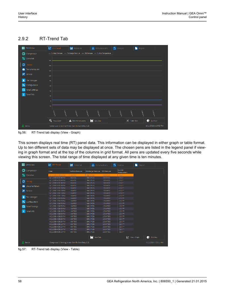
This screen displays real time (RT) panel data. This information can be displayed in either graph or table format.Up to ten different sets of data may be displayed at once. The chosen pens are listed in the legend panel if view-ing in graph format and at the top of the columns in grid format. All pens are updated every five seconds whileviewing this screen. The total range of time displayed at any given time is ten minutes.
fig.57: RT-Trend tab display (View - Table)
User interfaceHistory
Instruction Manual | GEA Omni™Control panel
58 GEA Refrigeration North America, Inc. | 806550_1 | Generated 21.01.2015
2.9.3 Chart Tab
fig.58: Chart tab display (View - Graph)
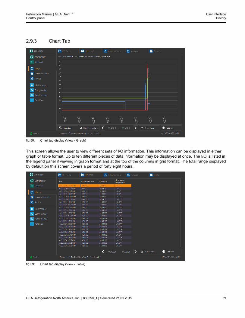
This screen allows the user to view different sets of I/O information. This information can be displayed in eithergraph or table format. Up to ten different pieces of data information may be displayed at once. The I/O is listed inthe legend panel if viewing in graph format and at the top of the columns in grid format. The total range displayedby default on this screen covers a period of forty eight hours.
fig.59: Chart tab display (View - Table)
Instruction Manual | GEA Omni™Control panel
User interfaceHistory
GEA Refrigeration North America, Inc. | 806550_1 | Generated 21.01.2015 59
2.9.4 Annunciations Tab
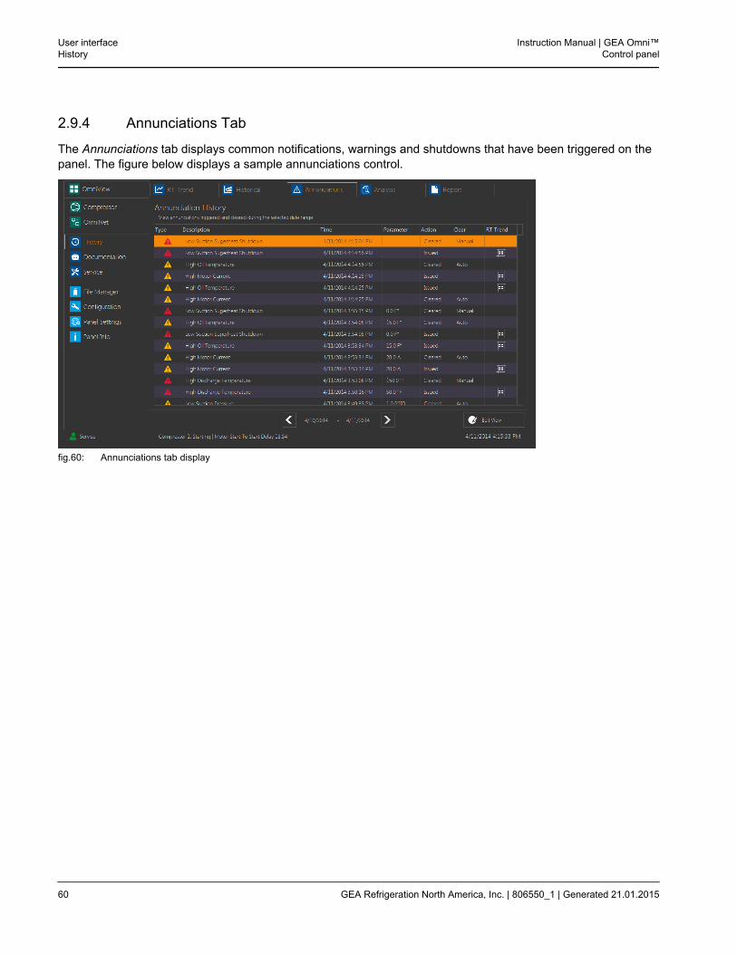
The Annunciations tab displays common notifications, warnings and shutdowns that have been triggered on thepanel. The figure below displays a sample annunciations control.
fig.60: Annunciations tab display
User interfaceHistory
Instruction Manual | GEA Omni™Control panel
60 GEA Refrigeration North America, Inc. | 806550_1 | Generated 21.01.2015
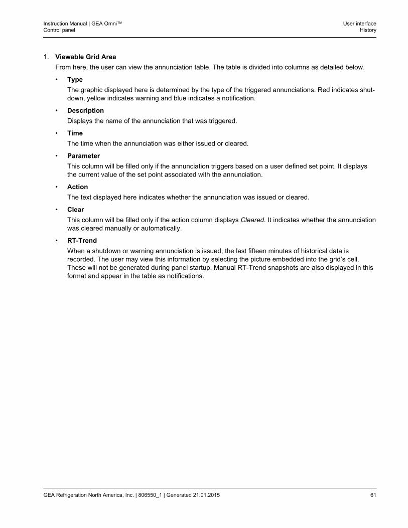
1. Viewable Grid AreaFrom here, the user can view the annunciation table. The table is divided into columns as detailed below.
• TypeThe graphic displayed here is determined by the type of the triggered annunciations. Red indicates shut-down, yellow indicates warning and blue indicates a notification.
• DescriptionDisplays the name of the annunciation that was triggered.
• TimeThe time when the annunciation was either issued or cleared.
• ParameterThis column will be filled only if the annunciation triggers based on a user defined set point. It displaysthe current value of the set point associated with the annunciation.
• ActionThe text displayed here indicates whether the annunciation was issued or cleared.
• ClearThis column will be filled only if the action column displays Cleared. It indicates whether the annunciationwas cleared manually or automatically.
• RT-TrendWhen a shutdown or warning annunciation is issued, the last fifteen minutes of historical data isrecorded. The user may view this information by selecting the picture embedded into the grid’s cell.These will not be generated during panel startup. Manual RT-Trend snapshots are also displayed in thisformat and appear in the table as notifications.
Instruction Manual | GEA Omni™Control panel
User interfaceHistory
GEA Refrigeration North America, Inc. | 806550_1 | Generated 21.01.2015 61
2.9.5 Analysis Tab
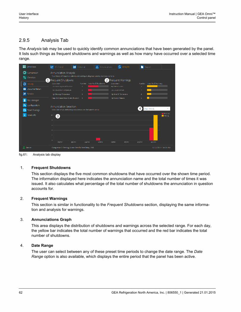
The Analysis tab may be used to quickly identify common annunciations that have been generated by the panel.It lists such things as frequent shutdowns and warnings as well as how many have occurred over a selected timerange.
fig.61: Analysis tab display
1. Frequent ShutdownsThis section displays the five most common shutdowns that have occurred over the shown time period.The information displayed here indicates the annunciation name and the total number of times it wasissued. It also calculates what percentage of the total number of shutdowns the annunciation in questionaccounts for.
2. Frequent WarningsThis section is similar in functionality to the Frequent Shutdowns section, displaying the same informa-tion and analysis for warnings.
3. Annunciations GraphThis area displays the distribution of shutdowns and warnings across the selected range. For each day,the yellow bar indicates the total number of warnings that occurred and the red bar indicates the totalnumber of shutdowns.
4. Date RangeThe user can select between any of these preset time periods to change the date range. The DateRange option is also available, which displays the entire period that the panel has been active.
User interfaceHistory
Instruction Manual | GEA Omni™Control panel
62 GEA Refrigeration North America, Inc. | 806550_1 | Generated 21.01.2015
2.9.6 Reporting Tab
This screen is used to generate custom reports from the panel’s historical data.
fig.62: Reporting tab display
1. Date RangeThis is the time period to be included in the report.
2. Data SelectionThese options are used to select what information should be included in the report. Alternatively, alloptions may be selected or deselected through the Check All and Uncheck All buttons respectively.
• Min/Max/MeanThis will calculate the min/max and mean for any of the selected I/O. The I/O is selected on the rightside of this tool.
• ShutdownThis will display every shutdown that has been issued or cleared. It will list the description, type anddate.
• WarningThis will display every warning that has been issued or cleared. It will list the description, type anddate.
• NotificationThis will display every notification that has been issued or cleared. It will list the description, type anddate.
3. Preview ReportThis will generate a temporary pdf file displaying all of the selected information.
Instruction Manual | GEA Omni™Control panel
User interfaceHistory
GEA Refrigeration North America, Inc. | 806550_1 | Generated 21.01.2015 63
4. Save ReportThis will save the report to the connected USB drive.
5. Select PensThis section is used to select which specific sets of data will be included in the report. A check mark inthe box to the left will indicate that the pen in question is selected.
2.10 Documentation
The Documentation screen contains reference materials regarding panel or system functionality. The informationdisplayed here is divided across two tabs, as detailed in the sections below.
2.10.1 Documents Tab
fig.63: Documents tile display
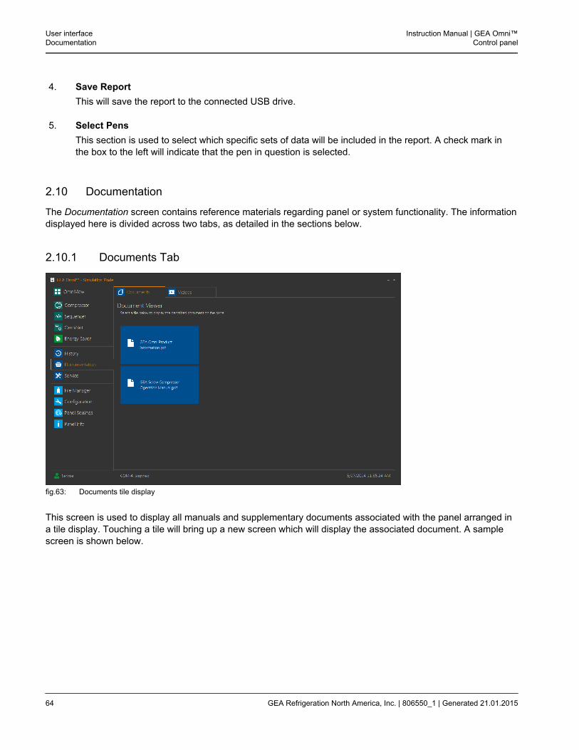
This screen is used to display all manuals and supplementary documents associated with the panel arranged ina tile display. Touching a tile will bring up a new screen which will display the associated document. A samplescreen is shown below.
User interfaceDocumentation
Instruction Manual | GEA Omni™Control panel
64 GEA Refrigeration North America, Inc. | 806550_1 | Generated 21.01.2015
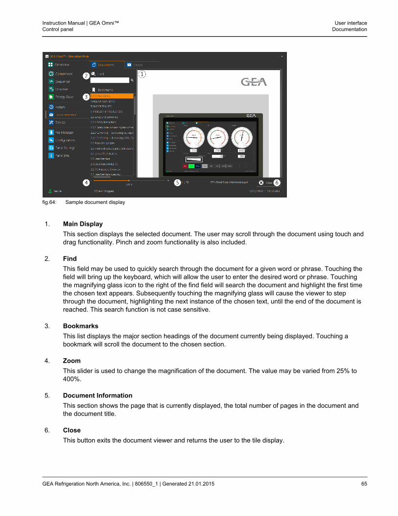
fig.64: Sample document display
1. Main DisplayThis section displays the selected document. The user may scroll through the document using touch anddrag functionality. Pinch and zoom functionality is also included.
2. FindThis field may be used to quickly search through the document for a given word or phrase. Touching thefield will bring up the keyboard, which will allow the user to enter the desired word or phrase. Touchingthe magnifying glass icon to the right of the find field will search the document and highlight the first timethe chosen text appears. Subsequently touching the magnifying glass will cause the viewer to stepthrough the document, highlighting the next instance of the chosen text, until the end of the document isreached. This search function is not case sensitive.
3. BookmarksThis list displays the major section headings of the document currently being displayed. Touching abookmark will scroll the document to the chosen section.
4. ZoomThis slider is used to change the magnification of the document. The value may be varied from 25% to400%.
5. Document InformationThis section shows the page that is currently displayed, the total number of pages in the document andthe document title.
6. CloseThis button exits the document viewer and returns the user to the tile display.
Instruction Manual | GEA Omni™Control panel
User interfaceDocumentation
GEA Refrigeration North America, Inc. | 806550_1 | Generated 21.01.2015 65
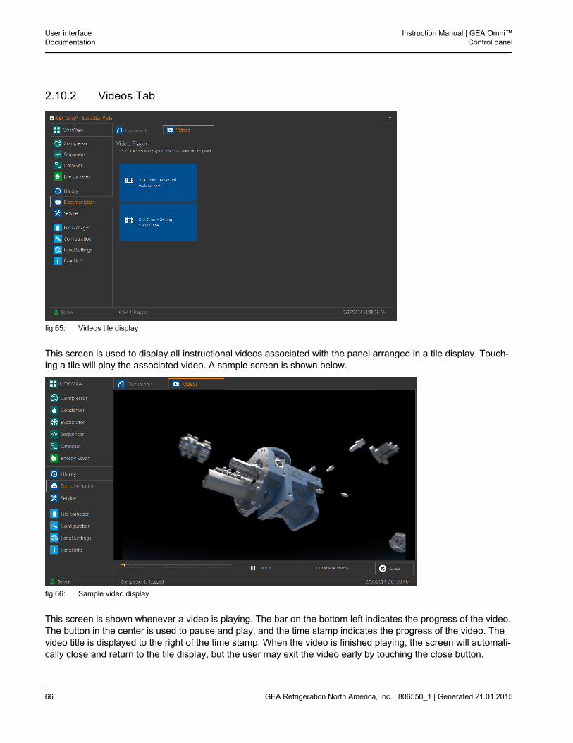
2.10.2 Videos Tab
fig.65: Videos tile display
This screen is used to display all instructional videos associated with the panel arranged in a tile display. Touch-ing a tile will play the associated video. A sample screen is shown below.
fig.66: Sample video display
This screen is shown whenever a video is playing. The bar on the bottom left indicates the progress of the video.The button in the center is used to pause and play, and the time stamp indicates the progress of the video. Thevideo title is displayed to the right of the time stamp. When the video is finished playing, the screen will automati-cally close and return to the tile display, but the user may exit the video early by touching the close button.
User interfaceDocumentation
Instruction Manual | GEA Omni™Control panel
66 GEA Refrigeration North America, Inc. | 806550_1 | Generated 21.01.2015
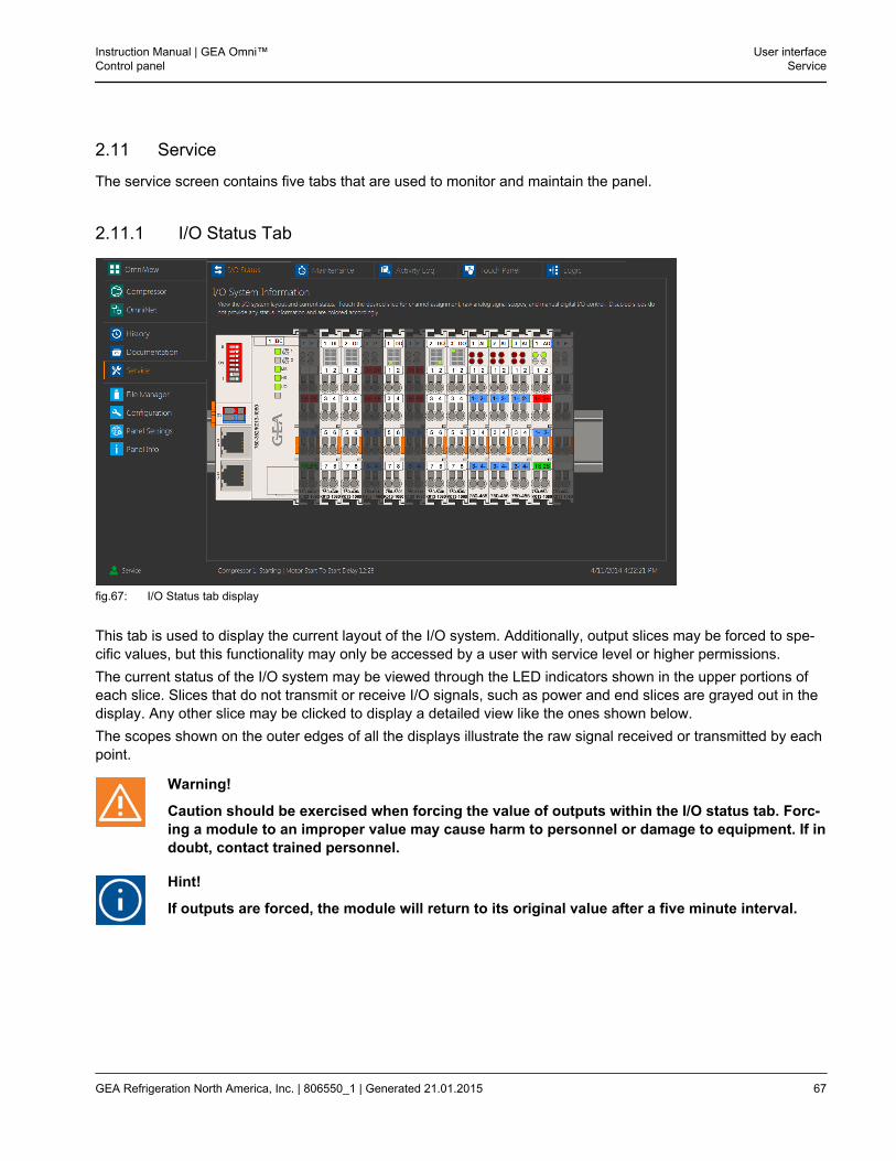
2.11 Service
The service screen contains five tabs that are used to monitor and maintain the panel.
2.11.1 I/O Status Tab
fig.67: I/O Status tab display
This tab is used to display the current layout of the I/O system. Additionally, output slices may be forced to spe-cific values, but this functionality may only be accessed by a user with service level or higher permissions.The current status of the I/O system may be viewed through the LED indicators shown in the upper portions ofeach slice. Slices that do not transmit or receive I/O signals, such as power and end slices are grayed out in thedisplay. Any other slice may be clicked to display a detailed view like the ones shown below.The scopes shown on the outer edges of all the displays illustrate the raw signal received or transmitted by eachpoint.
Warning!
Caution should be exercised when forcing the value of outputs within the I/O status tab. Forc-ing a module to an improper value may cause harm to personnel or damage to equipment. If indoubt, contact trained personnel.
Hint!
If outputs are forced, the module will return to its original value after a five minute interval.
Instruction Manual | GEA Omni™Control panel
User interfaceService
GEA Refrigeration North America, Inc. | 806550_1 | Generated 21.01.2015 67
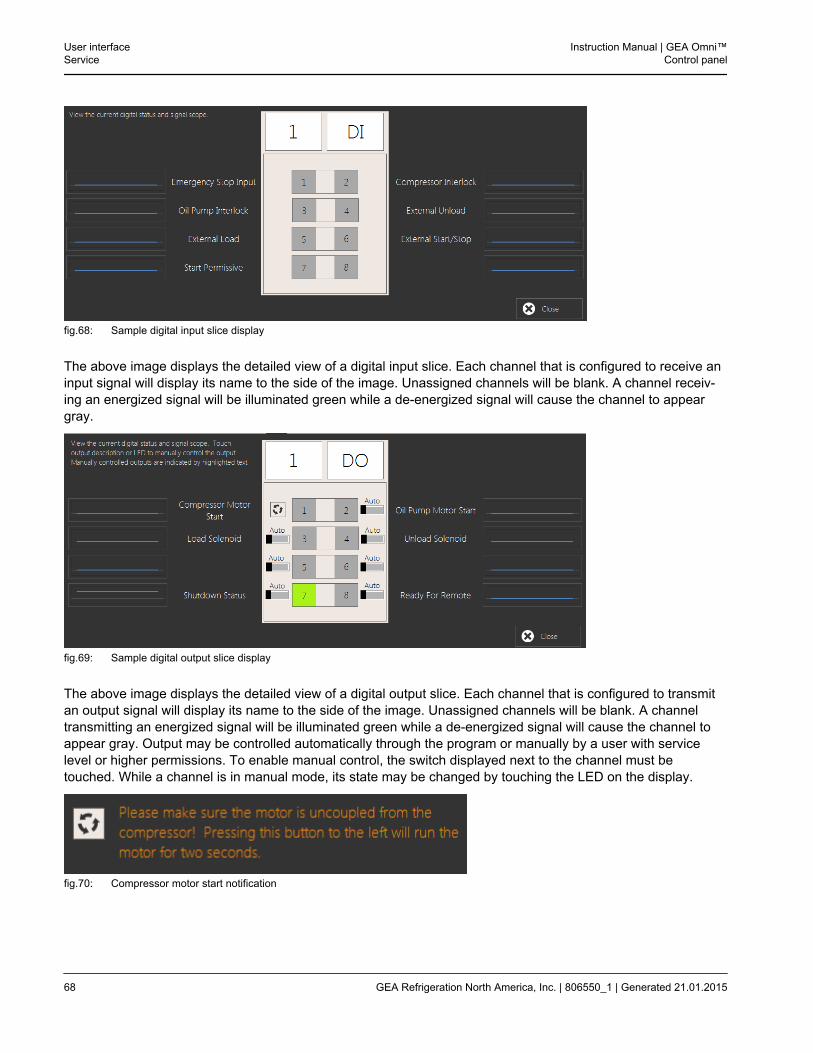
fig.68: Sample digital input slice display
The above image displays the detailed view of a digital input slice. Each channel that is configured to receive aninput signal will display its name to the side of the image. Unassigned channels will be blank. A channel receiv-ing an energized signal will be illuminated green while a de-energized signal will cause the channel to appeargray.
fig.69: Sample digital output slice display
The above image displays the detailed view of a digital output slice. Each channel that is configured to transmitan output signal will display its name to the side of the image. Unassigned channels will be blank. A channeltransmitting an energized signal will be illuminated green while a de-energized signal will cause the channel toappear gray. Output may be controlled automatically through the program or manually by a user with servicelevel or higher permissions. To enable manual control, the switch displayed next to the channel must betouched. While a channel is in manual mode, its state may be changed by touching the LED on the display.
fig.70: Compressor motor start notification
User interfaceService
Instruction Manual | GEA Omni™Control panel
68 GEA Refrigeration North America, Inc. | 806550_1 | Generated 21.01.2015
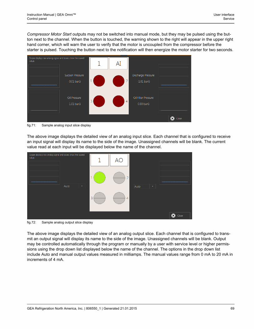
Compressor Motor Start outputs may not be switched into manual mode, but they may be pulsed using the but-ton next to the channel. When the button is touched, the warning shown to the right will appear in the upper righthand corner, which will warn the user to verify that the motor is uncoupled from the compressor before thestarter is pulsed. Touching the button next to the notification will then energize the motor starter for two seconds.
fig.71: Sample analog input slice display
The above image displays the detailed view of an analog input slice. Each channel that is configured to receivean input signal will display its name to the side of the image. Unassigned channels will be blank. The currentvalue read at each input will be displayed below the name of the channel.
fig.72: Sample analog output slice display
The above image displays the detailed view of an analog output slice. Each channel that is configured to trans-mit an output signal will display its name to the side of the image. Unassigned channels will be blank. Outputmay be controlled automatically through the program or manually by a user with service level or higher permis-sions using the drop down list displayed below the name of the channel. The options in the drop down listinclude Auto and manual output values measured in milliamps. The manual values range from 0 mA to 20 mA inincrements of 4 mA.
Instruction Manual | GEA Omni™Control panel
User interfaceService
GEA Refrigeration North America, Inc. | 806550_1 | Generated 21.01.2015 69
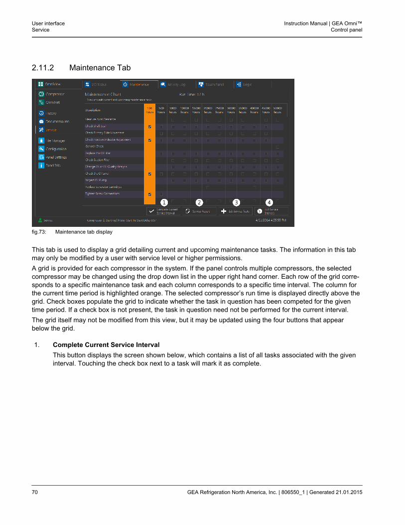
2.11.2 Maintenance Tab
fig.73: Maintenance tab display
This tab is used to display a grid detailing current and upcoming maintenance tasks. The information in this tabmay only be modified by a user with service level or higher permissions.A grid is provided for each compressor in the system. If the panel controls multiple compressors, the selectedcompressor may be changed using the drop down list in the upper right hand corner. Each row of the grid corre-sponds to a specific maintenance task and each column corresponds to a specific time interval. The column forthe current time period is highlighted orange. The selected compressor’s run time is displayed directly above thegrid. Check boxes populate the grid to indicate whether the task in question has been competed for the giventime period. If a check box is not present, the task in question need not be performed for the current interval.The grid itself may not be modified from this view, but it may be updated using the four buttons that appearbelow the grid.
1. Complete Current Service IntervalThis button displays the screen shown below, which contains a list of all tasks associated with the giveninterval. Touching the check box next to a task will mark it as complete.
User interfaceService
Instruction Manual | GEA Omni™Control panel
70 GEA Refrigeration North America, Inc. | 806550_1 | Generated 21.01.2015
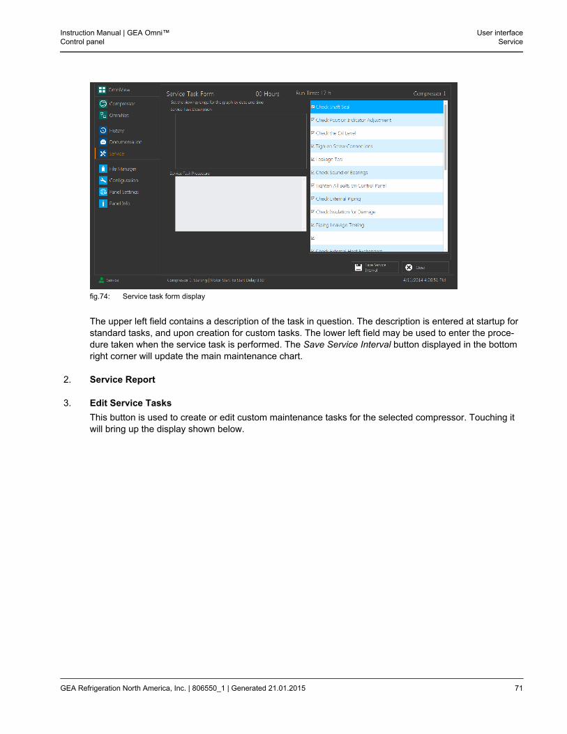
fig.74: Service task form display
The upper left field contains a description of the task in question. The description is entered at startup forstandard tasks, and upon creation for custom tasks. The lower left field may be used to enter the proce-dure taken when the service task is performed. The Save Service Interval button displayed in the bottomright corner will update the main maintenance chart.
2. Service Report
3. Edit Service TasksThis button is used to create or edit custom maintenance tasks for the selected compressor. Touching itwill bring up the display shown below.
Instruction Manual | GEA Omni™Control panel
User interfaceService
GEA Refrigeration North America, Inc. | 806550_1 | Generated 21.01.2015 71
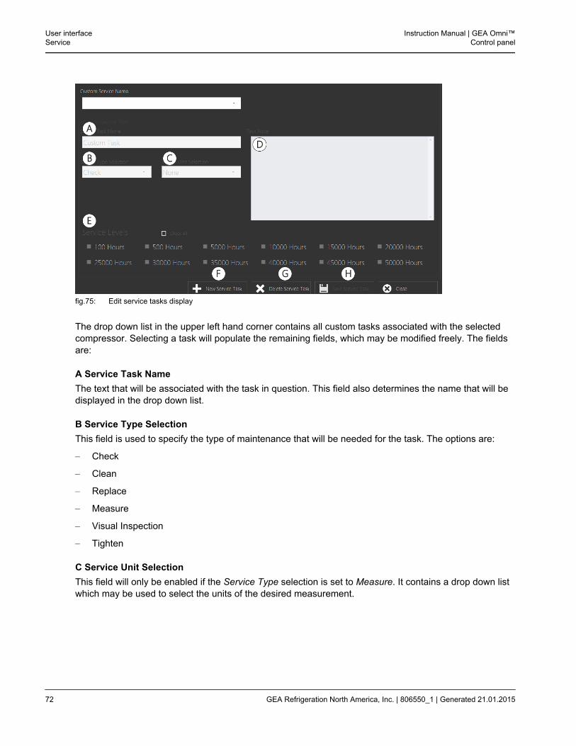
fig.75: Edit service tasks display
The drop down list in the upper left hand corner contains all custom tasks associated with the selectedcompressor. Selecting a task will populate the remaining fields, which may be modified freely. The fieldsare:
A Service Task NameThe text that will be associated with the task in question. This field also determines the name that will bedisplayed in the drop down list.
B Service Type SelectionThis field is used to specify the type of maintenance that will be needed for the task. The options are:
– Check
– Clean
– Replace
– Measure
– Visual Inspection
– Tighten
C Service Unit SelectionThis field will only be enabled if the Service Type selection is set to Measure. It contains a drop down listwhich may be used to select the units of the desired measurement.
User interfaceService
Instruction Manual | GEA Omni™Control panel
72 GEA Refrigeration North America, Inc. | 806550_1 | Generated 21.01.2015
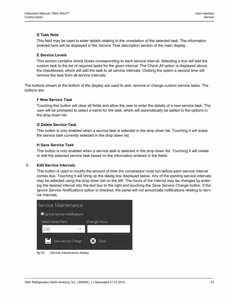
D Task NoteThis field may be used to enter details relating to the completion of the selected task. The informationentered here will be displayed in the Service Task description section of the main display.
E Service LevelsThis section contains check boxes corresponding to each service interval. Selecting a box will add thecustom task to the list of required tasks for the given interval. The Check All option is displayed abovethe checkboxes, which will add the task to all service intervals. Clicking the option a second time willremove the task from all service intervals.
The buttons shown at the bottom of the display are used to add, remove or change custom service tasks. Thebuttons are:
F New Service TaskTouching this button will clear all fields and allow the user to enter the details of a new service task. Theuser will be prompted to select a name for the task, which will automatically be added to the options inthe drop down list.
G Delete Service TaskThis button is only enabled when a service task is selected in the drop down list. Touching it will erasethe service task currently selected in the drop down list.
H Save Service TaskThis button is only enabled when a service task is selected in the drop down list. Touching it will createor edit the selected service task based on the information entered in the fields.
4. Edit Service IntervalsThis button is used to modify the amount of time the compressor must run before each service intervalcomes due. Touching it will bring up the dialog box displayed below. Any of the existing service intervalsmay be selected using the drop down list on the left. The hours of the interval may be changed by enter-ing the desired interval into the text box to the right and touching the Save Service Change button. If theIgnore Service Notifications option is checked, the panel will not annunciate notifications relating to serv-ice intervals.
fig.76: Service maintenance display
Instruction Manual | GEA Omni™Control panel
User interfaceService
GEA Refrigeration North America, Inc. | 806550_1 | Generated 21.01.2015 73
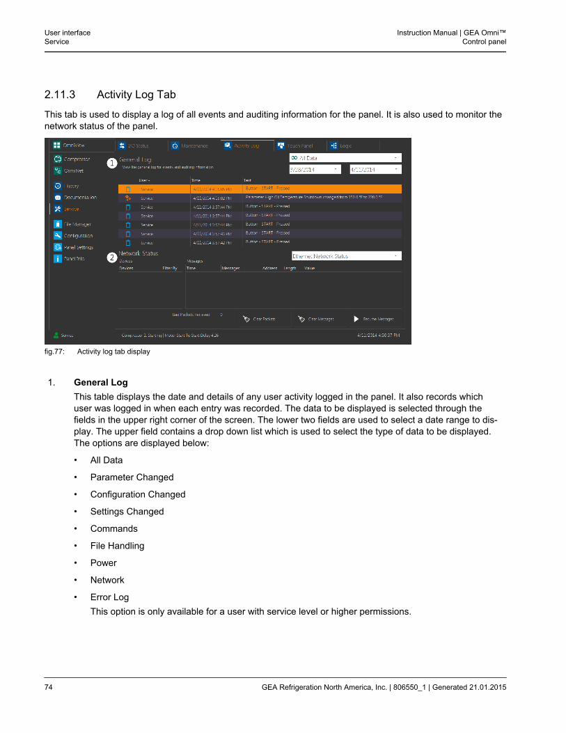
2.11.3 Activity Log Tab
This tab is used to display a log of all events and auditing information for the panel. It is also used to monitor thenetwork status of the panel.
fig.77: Activity log tab display
1. General LogThis table displays the date and details of any user activity logged in the panel. It also records whichuser was logged in when each entry was recorded. The data to be displayed is selected through thefields in the upper right corner of the screen. The lower two fields are used to select a date range to dis-play. The upper field contains a drop down list which is used to select the type of data to be displayed.The options are displayed below:
• All Data
• Parameter Changed
• Configuration Changed
• Settings Changed
• Commands
• File Handling
• Power
• Network
• Error LogThis option is only available for a user with service level or higher permissions.
User interfaceService
Instruction Manual | GEA Omni™Control panel
74 GEA Refrigeration North America, Inc. | 806550_1 | Generated 21.01.2015
2. Network StatusThis section contains two tables used to display information regarding networked devices. The net-work monitored may be either an ethernet network or a serial network. The type of network to monitoris selected using the drop down list above the table. The table on the left displays the name and IPaddress of each device. Touching an IP address in this list will filter the Devices and only displayones with a matching IP address. The table on the right displays any messages received from a net-worked device and displays the Time, Message, Address, Length and Value received. The messagetable may be cleared with the Clear Messages button, or halted temporarily with the Pause Messagesbutton, both found in the bottom right hand corner of the display. A count is also kept of any errorsfound in packets received from the networked devices. Both types of network may receive a badpacket, and a serial network may also have packets time out. A count for each of these conditionscan be found to the left of the buttons, and the Clear Packets button may be used to return the countto zero.
Instruction Manual | GEA Omni™Control panel
User interfaceService
GEA Refrigeration North America, Inc. | 806550_1 | Generated 21.01.2015 75
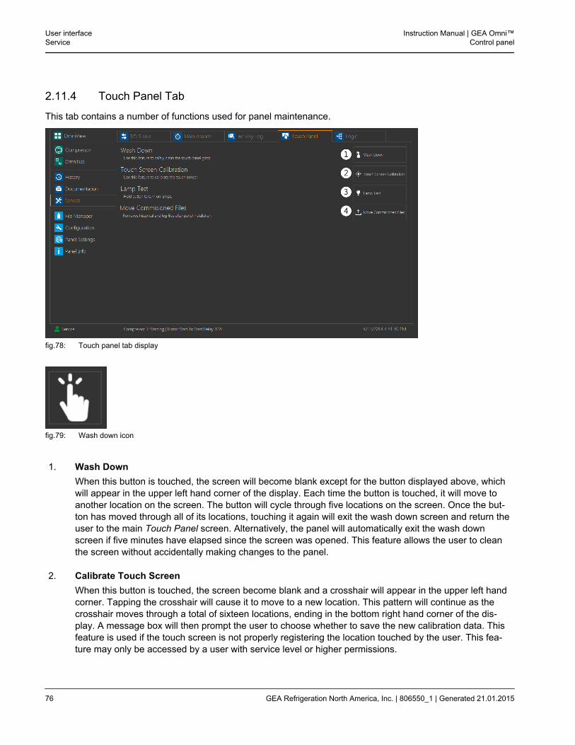
2.11.4 Touch Panel Tab
This tab contains a number of functions used for panel maintenance.
fig.78: Touch panel tab display
fig.79: Wash down icon
1. Wash DownWhen this button is touched, the screen will become blank except for the button displayed above, whichwill appear in the upper left hand corner of the display. Each time the button is touched, it will move toanother location on the screen. The button will cycle through five locations on the screen. Once the but-ton has moved through all of its locations, touching it again will exit the wash down screen and return theuser to the main Touch Panel screen. Alternatively, the panel will automatically exit the wash downscreen if five minutes have elapsed since the screen was opened. This feature allows the user to cleanthe screen without accidentally making changes to the panel.
2. Calibrate Touch ScreenWhen this button is touched, the screen become blank and a crosshair will appear in the upper left handcorner. Tapping the crosshair will cause it to move to a new location. This pattern will continue as thecrosshair moves through a total of sixteen locations, ending in the bottom right hand corner of the dis-play. A message box will then prompt the user to choose whether to save the new calibration data. Thisfeature is used if the touch screen is not properly registering the location touched by the user. This fea-ture may only be accessed by a user with service level or higher permissions.
User interfaceService
Instruction Manual | GEA Omni™Control panel
76 GEA Refrigeration North America, Inc. | 806550_1 | Generated 21.01.2015
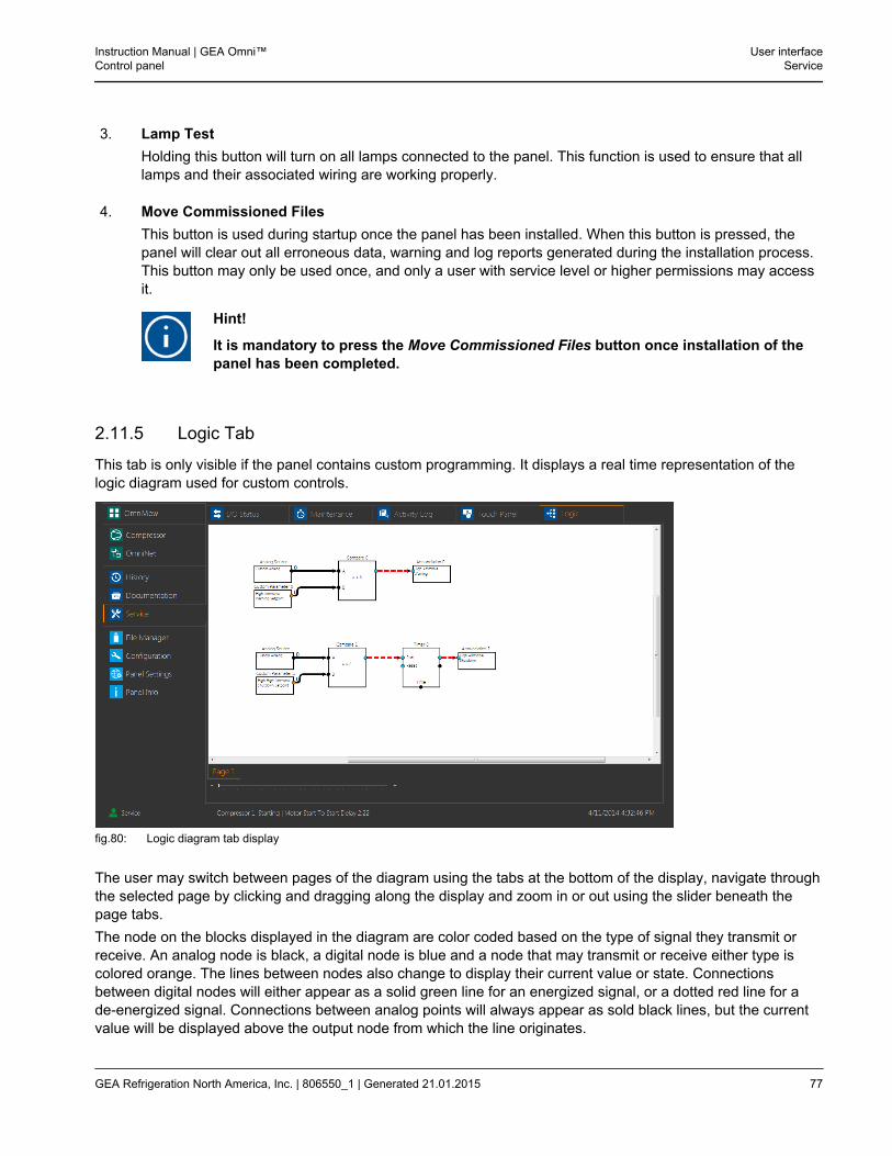
3. Lamp TestHolding this button will turn on all lamps connected to the panel. This function is used to ensure that alllamps and their associated wiring are working properly.
4. Move Commissioned FilesThis button is used during startup once the panel has been installed. When this button is pressed, thepanel will clear out all erroneous data, warning and log reports generated during the installation process.This button may only be used once, and only a user with service level or higher permissions may accessit.
Hint!
It is mandatory to press the Move Commissioned Files button once installation of thepanel has been completed.
2.11.5 Logic Tab
This tab is only visible if the panel contains custom programming. It displays a real time representation of thelogic diagram used for custom controls.
fig.80: Logic diagram tab display
The user may switch between pages of the diagram using the tabs at the bottom of the display, navigate throughthe selected page by clicking and dragging along the display and zoom in or out using the slider beneath thepage tabs.The node on the blocks displayed in the diagram are color coded based on the type of signal they transmit orreceive. An analog node is black, a digital node is blue and a node that may transmit or receive either type iscolored orange. The lines between nodes also change to display their current value or state. Connectionsbetween digital nodes will either appear as a solid green line for an energized signal, or a dotted red line for ade-energized signal. Connections between analog points will always appear as sold black lines, but the currentvalue will be displayed above the output node from which the line originates.
Instruction Manual | GEA Omni™Control panel
User interfaceService
GEA Refrigeration North America, Inc. | 806550_1 | Generated 21.01.2015 77
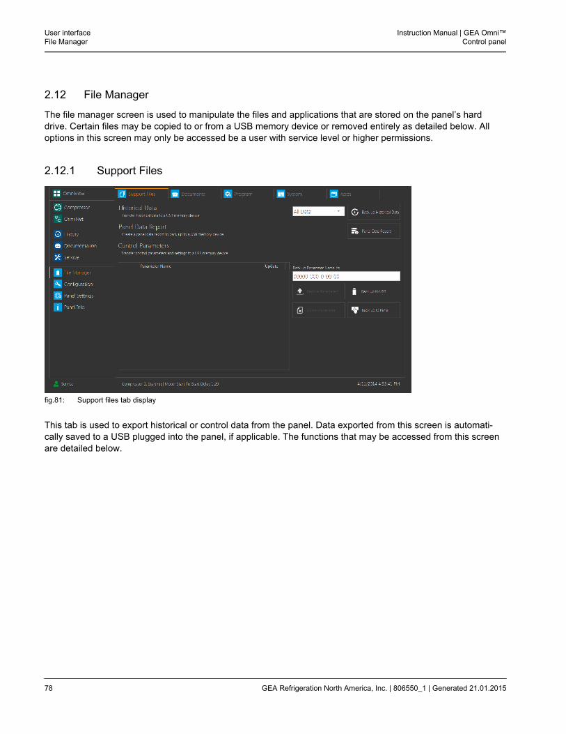
2.12 File Manager
The file manager screen is used to manipulate the files and applications that are stored on the panel’s harddrive. Certain files may be copied to or from a USB memory device or removed entirely as detailed below. Alloptions in this screen may only be accessed be a user with service level or higher permissions.
2.12.1 Support Files
fig.81: Support files tab display
This tab is used to export historical or control data from the panel. Data exported from this screen is automati-cally saved to a USB plugged into the panel, if applicable. The functions that may be accessed from this screenare detailed below.
User interfaceFile Manager
Instruction Manual | GEA Omni™Control panel
78 GEA Refrigeration North America, Inc. | 806550_1 | Generated 21.01.2015
1. Historical DataThis section contains a drop down list which is used to select a range of time from which to export histor-ical data to a USB. The options are:
• All Data
• One Week
• Two Weeks
• One Month
• Date RangeIf the Date Range option is selected, two additional fields will appear which will prompt the user to entera custom start and end date for the historical data range. Once a date range has been chosen, the Backup Historical Data button displayed to the far right of the section may be clicked, which will save a histor-ian file, of file type .ohist, to the GEA RT folder of the USB. If no GEA RT folder is found, one will becreated automatically. The name the file is saved under is generated using the project number and thecurrent date.
Instruction Manual | GEA Omni™Control panel
User interfaceFile Manager
GEA Refrigeration North America, Inc. | 806550_1 | Generated 21.01.2015 79
2. Panel Data ReportTouching the button to the right of this section will generate a pdf document containing important infor-mation on all analog and digital I/O associated with the panel. The information in the panel data reportincludes:
• ABThe Allen Bradley address of the given data point.
• Modbus AddressThe Modbus location which the user may read from or write to for the given data point.
• DescriptionThe name associated with the given data point.
• Designation/ ValueThe I/O slice and channel associated with the given data point, if applicable. Designation is used foranalog data while Value is used for digital data.
• RangeThe maximum and minimum value that the given data point may contain. This column is only shownfor Analog data.
• StateThe reading that will be displayed for the given data point when it is energized or de-energized. Thiscolumn is only shown for digital data.
• ScaleThis column indicates the number of decimal points the chosen data point is configured to read.
• R/WThis column determines whether the user may read or write to the given data point. An R indicatesthat the data point is read-only, and may be viewed but not modified by the user. R/W indicates thatthe data point is Read/Write enabled, meaning that the user may view and modify the value freely. Wwould indicate write-only, but is not used in the panel data report.
3. Control ParametersThis section allows the user to save a specific set of parameter values to a USB or the panel. The tableto the left of the section displays all .oprms files found on the USB and panel memory which may beused to restore parameters to the panel or delete parameter files from either location. The parametersmay be manipulated through the four buttons displayed at the bottom right of the screen. The buttonsare:
• Back up to USBThis button is used to save the current values of all custom parameters on the panel to an .oprms filein the GEA RT folder on the USB. If such a folder does not exist, it will be created automatically. Thedefault name of the file is the number of the configuration, but a custom name may be entered intothe text field above the button.
User interfaceFile Manager
Instruction Manual | GEA Omni™Control panel
80 GEA Refrigeration North America, Inc. | 806550_1 | Generated 21.01.2015
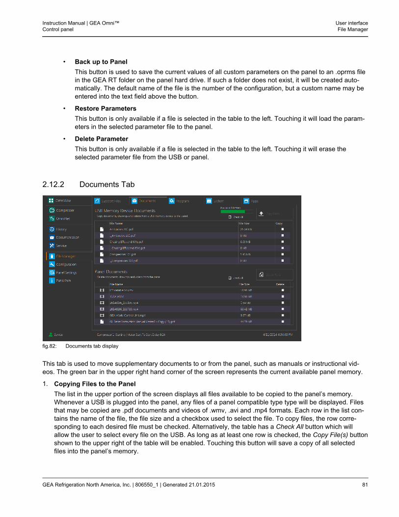
• Back up to PanelThis button is used to save the current values of all custom parameters on the panel to an .oprms filein the GEA RT folder on the panel hard drive. If such a folder does not exist, it will be created auto-matically. The default name of the file is the number of the configuration, but a custom name may beentered into the text field above the button.
• Restore ParametersThis button is only available if a file is selected in the table to the left. Touching it will load the param-eters in the selected parameter file to the panel.
• Delete ParameterThis button is only available if a file is selected in the table to the left. Touching it will erase theselected parameter file from the USB or panel.
2.12.2 Documents Tab
fig.82: Documents tab display
This tab is used to move supplementary documents to or from the panel, such as manuals or instructional vid-eos. The green bar in the upper right hand corner of the screen represents the current available panel memory.
1. Copying Files to the PanelThe list in the upper portion of the screen displays all files available to be copied to the panel’s memory.Whenever a USB is plugged into the panel, any files of a panel compatible type type will be displayed. Filesthat may be copied are .pdf documents and videos of .wmv, .avi and .mp4 formats. Each row in the list con-tains the name of the file, the file size and a checkbox used to select the file. To copy files, the row corre-sponding to each desired file must be checked. Alternatively, the table has a Check All button which willallow the user to select every file on the USB. As long as at least one row is checked, the Copy File(s) buttonshown to the upper right of the table will be enabled. Touching this button will save a copy of all selectedfiles into the panel’s memory.
Instruction Manual | GEA Omni™Control panel
User interfaceFile Manager
GEA Refrigeration North America, Inc. | 806550_1 | Generated 21.01.2015 81
2. Copying or Deleting Files from the PanelThe list in the lower portion of the screen displays all files currently saved to the panel’s memory. Each rowin the list contains the name of the file, the file size and a checkbox used to select the file. Files may beselected from the list using the checkboxes in the rightmost column. Alternatively, the table has a Check Allbutton which will allow the user to select every file on the panel. As long as at least one row is checked, theDelete File(s) and Copy File(s) buttons shown to the upper right of the table will be enabled. Touching theDelete File(s) button will remove all selected files from the panel’s memory. Touching the Copy File(s) buttonwill save a copy of each selected file to a USB plugged into the panel.
User interfaceFile Manager
Instruction Manual | GEA Omni™Control panel
82 GEA Refrigeration North America, Inc. | 806550_1 | Generated 21.01.2015
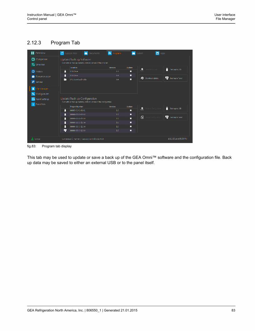
2.12.3 Program Tab
fig.83: Program tab display
This tab may be used to update or save a back up of the GEA Omni™ software and the configuration file. Backup data may be saved to either an external USB or to the panel itself.
Instruction Manual | GEA Omni™Control panel
User interfaceFile Manager
GEA Refrigeration North America, Inc. | 806550_1 | Generated 21.01.2015 83
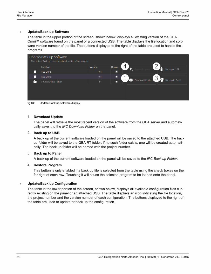
→ Update/Back up SoftwareThe table in the upper portion of the screen, shown below, displays all existing version of the GEAOmni™ software found on the panel or a connected USB. The table displays the file location and soft-ware version number of the file. The buttons displayed to the right of the table are used to handle theprograms.
fig.84: Update/Back up software display
1. Download UpdateThe panel will retrieve the most recent version of the software from the GEA server and automati-cally save it to the IPC Download Folder on the panel.
2. Back up to USBA back up of the current software loaded on the panel will be saved to the attached USB. The backup folder will be saved to the GEA RT folder. If no such folder exists, one will be created automati-cally. The back up folder will be named with the project number.
3. Back up to PanelA back up of the current software loaded on the panel will be saved to the IPC Back up Folder.
4. Restore ProgramThis button is only enabled if a back up file is selected from the table using the check boxes on thefar right of each row. Touching it will cause the selected program to be loaded onto the panel.
→ Update/Back up ConfigurationThe table in the lower portion of the screen, shown below, displays all available configuration files cur-rently existing on the panel or an attached USB. The table displays an icon indicating the file location,the project number and the version number of each configuration. The buttons displayed to the right ofthe table are used to update or back up the configuration.
User interfaceFile Manager
Instruction Manual | GEA Omni™Control panel
84 GEA Refrigeration North America, Inc. | 806550_1 | Generated 21.01.2015
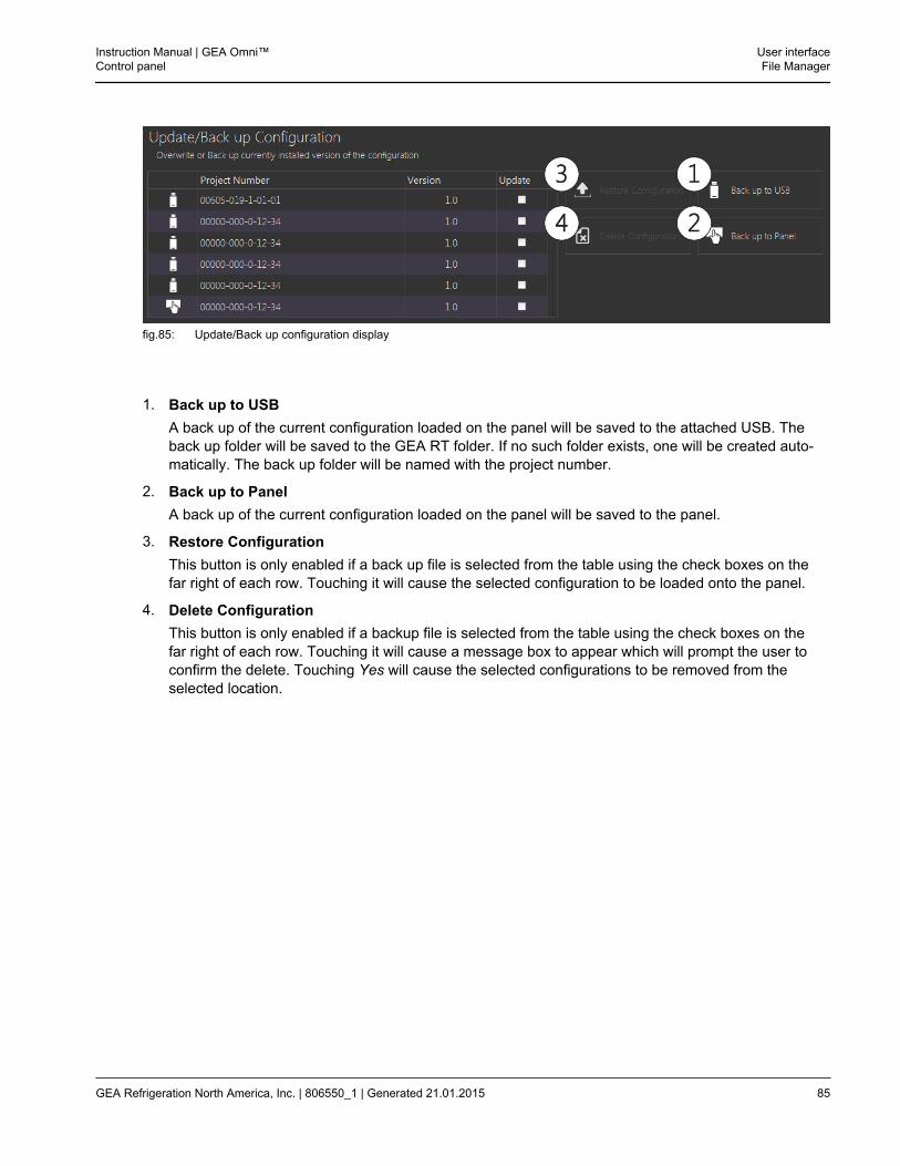
fig.85: Update/Back up configuration display
1. Back up to USBA back up of the current configuration loaded on the panel will be saved to the attached USB. Theback up folder will be saved to the GEA RT folder. If no such folder exists, one will be created auto-matically. The back up folder will be named with the project number.
2. Back up to PanelA back up of the current configuration loaded on the panel will be saved to the panel.
3. Restore ConfigurationThis button is only enabled if a back up file is selected from the table using the check boxes on thefar right of each row. Touching it will cause the selected configuration to be loaded onto the panel.
4. Delete ConfigurationThis button is only enabled if a backup file is selected from the table using the check boxes on thefar right of each row. Touching it will cause a message box to appear which will prompt the user toconfirm the delete. Touching Yes will cause the selected configurations to be removed from theselected location.
Instruction Manual | GEA Omni™Control panel
User interfaceFile Manager
GEA Refrigeration North America, Inc. | 806550_1 | Generated 21.01.2015 85
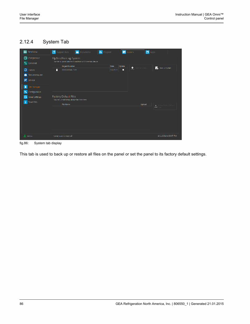
2.12.4 System Tab
fig.86: System tab display
This tab is used to back up or restore all files on the panel or set the panel to its factory default settings.
User interfaceFile Manager
Instruction Manual | GEA Omni™Control panel
86 GEA Refrigeration North America, Inc. | 806550_1 | Generated 21.01.2015
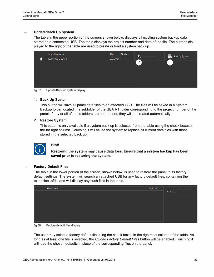
→ Update/Back Up SystemThe table in the upper portion of the screen, shown below, displays all existing system backup datastored on a connected USB. The table displays the project number and date of the file. The buttons dis-played to the right of the table are used to create or load a system back up.
fig.87: Update/Back up system display
1. Back Up SystemThis button will save all panel data files to an attached USB. The files will be saved in a SystemBackup folder located in a subfolder of the GEA RT folder corresponding to the project number of thepanel. If any or all of these folders are not present, they will be created automatically.
2. Restore SystemThis button is only available if a system back up is selected from the table using the check boxes inthe far right column. Touching it will cause the system to replace its current data files with thosestored in the selected back up.
Hint!
Restoring the system may cause data loss. Ensure that a system backup has beensaved prior to restoring the system.
→ Factory Default FilesThe table in the lower portion of the screen, shown below, is used to restore the panel to its factorydefault settings. The system will search an attached USB for any factory default files, containing theextension .ofds, and will display any such files in the table.
fig.88: Factory default files display
The user may select a factory default file using the check boxes in the rightmost column of the table. Aslong as at least one file is selected, the Upload Factory Default Files button will be enabled. Touching itwill load the chosen defaults in place of the corresponding files on the panel.
Instruction Manual | GEA Omni™Control panel
User interfaceFile Manager
GEA Refrigeration North America, Inc. | 806550_1 | Generated 21.01.2015 87
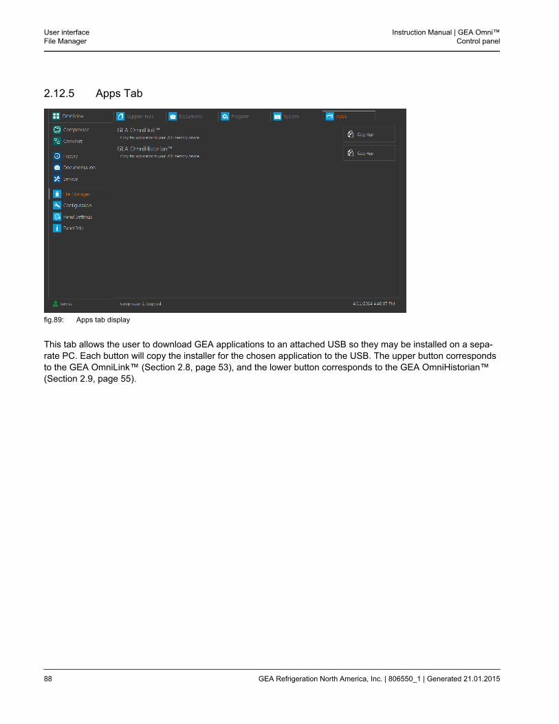
2.12.5 Apps Tab
fig.89: Apps tab display
This tab allows the user to download GEA applications to an attached USB so they may be installed on a sepa-rate PC. Each button will copy the installer for the chosen application to the USB. The upper button correspondsto the GEA OmniLink™ (Section 2.8, page 53), and the lower button corresponds to the GEA OmniHistorian™(Section 2.9, page 55).
User interfaceFile Manager
Instruction Manual | GEA Omni™Control panel
88 GEA Refrigeration North America, Inc. | 806550_1 | Generated 21.01.2015
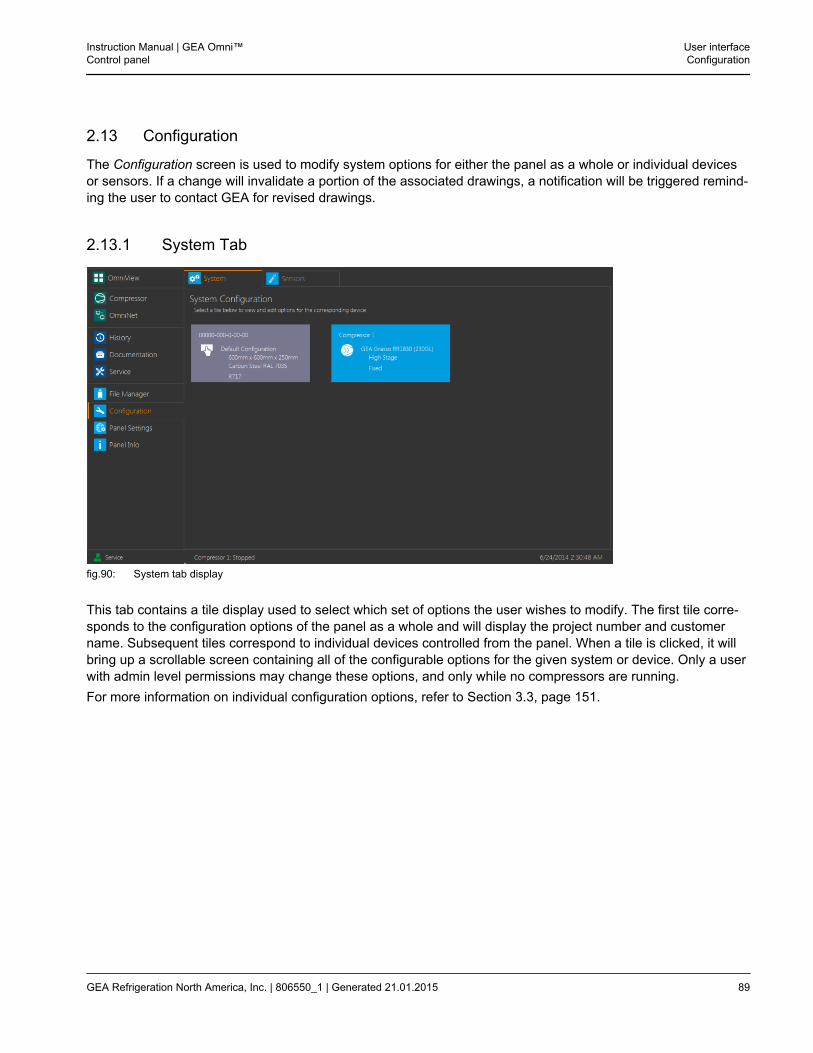
2.13 Configuration
The Configuration screen is used to modify system options for either the panel as a whole or individual devicesor sensors. If a change will invalidate a portion of the associated drawings, a notification will be triggered remind-ing the user to contact GEA for revised drawings.
2.13.1 System Tab
fig.90: System tab display
This tab contains a tile display used to select which set of options the user wishes to modify. The first tile corre-sponds to the configuration options of the panel as a whole and will display the project number and customername. Subsequent tiles correspond to individual devices controlled from the panel. When a tile is clicked, it willbring up a scrollable screen containing all of the configurable options for the given system or device. Only a userwith admin level permissions may change these options, and only while no compressors are running.For more information on individual configuration options, refer to Section 3.3, page 151.
Instruction Manual | GEA Omni™Control panel
User interfaceConfiguration
GEA Refrigeration North America, Inc. | 806550_1 | Generated 21.01.2015 89

2.13.2 Sensors Tab
fig.91: Sensors tab display
This tab is used to adjust the range of sensors monitored by the panel. The table is divided into nine columns.The leftmost column contains an icon that indicates whether the chosen point is an input or output. A greenarrow pointing to the right indicates that the point is an input, and a blue arrow pointing to the left indicates thatthe point is an output. The remaining channels are detailed below.
1. ChannelThe text in this column indicates the slice number and channel that the chosen point occupies in the I/O sys-tem.
2. DescriptionThis column contains the name of the chosen point.
3. MinThis column contains the lowest allowable value for the chosen point during normal panel operation.
4. MeasuredThis column contains the calibrated value read from or transmitted to the chosen point.
5. MaxThis column contains the highest allowable value for the chosen point during normal panel operation.
6. Raw ScaledThis column contains the Raw Signal received by associated sensor scaled between the selected minimumand maximum values.
7. OffsetThis column contains the value that is added to the reading displayed in the Raw Scaled column to obtainthe measured value for the sensor.
User interfaceConfiguration
Instruction Manual | GEA Omni™Control panel
90 GEA Refrigeration North America, Inc. | 806550_1 | Generated 21.01.2015
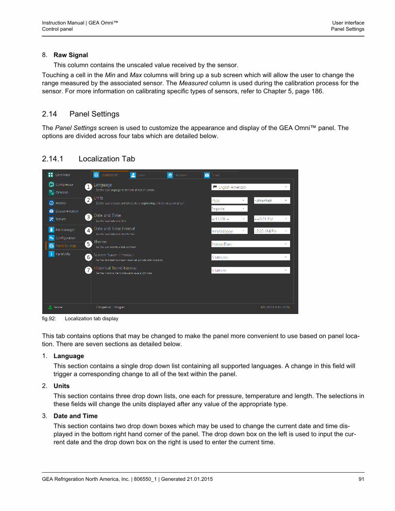
8. Raw SignalThis column contains the unscaled value received by the sensor.
Touching a cell in the Min and Max columns will bring up a sub screen which will allow the user to change therange measured by the associated sensor. The Measured column is used during the calibration process for thesensor. For more information on calibrating specific types of sensors, refer to Chapter 5, page 186.
2.14 Panel Settings
The Panel Settings screen is used to customize the appearance and display of the GEA Omni™ panel. Theoptions are divided across four tabs which are detailed below.
2.14.1 Localization Tab
fig.92: Localization tab display
This tab contains options that may be changed to make the panel more convenient to use based on panel loca-tion. There are seven sections as detailed below.
1. LanguageThis section contains a single drop down list containing all supported languages. A change in this field willtrigger a corresponding change to all of the text within the panel.
2. UnitsThis section contains three drop down lists, one each for pressure, temperature and length. The selections inthese fields will change the units displayed after any value of the appropriate type.
3. Date and TimeThis section contains two drop down boxes which may be used to change the current date and time dis-played in the bottom right hand corner of the panel. The drop down box on the left is used to input the cur-rent date and the drop down box on the right is used to enter the current time.
Instruction Manual | GEA Omni™Control panel
User interfacePanel Settings
GEA Refrigeration North America, Inc. | 806550_1 | Generated 21.01.2015 91
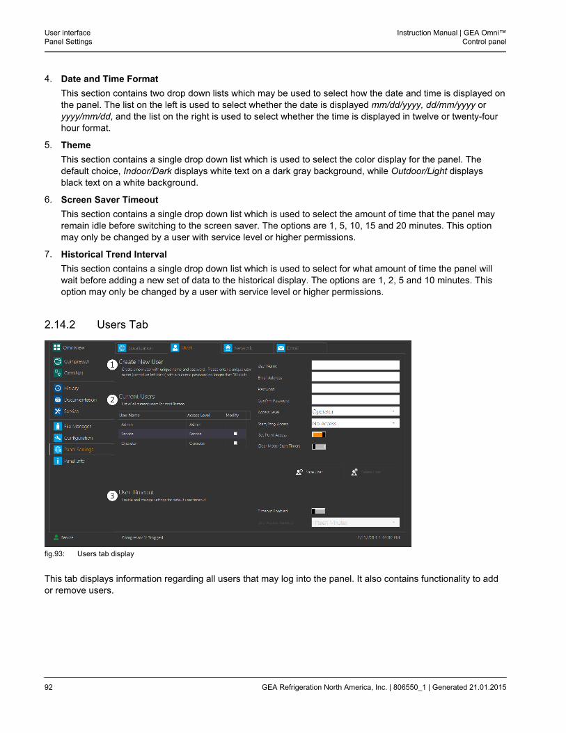
4. Date and Time FormatThis section contains two drop down lists which may be used to select how the date and time is displayed onthe panel. The list on the left is used to select whether the date is displayed mm/dd/yyyy, dd/mm/yyyy oryyyy/mm/dd, and the list on the right is used to select whether the time is displayed in twelve or twenty-fourhour format.
5. ThemeThis section contains a single drop down list which is used to select the color display for the panel. Thedefault choice, Indoor/Dark displays white text on a dark gray background, while Outdoor/Light displaysblack text on a white background.
6. Screen Saver TimeoutThis section contains a single drop down list which is used to select the amount of time that the panel mayremain idle before switching to the screen saver. The options are 1, 5, 10, 15 and 20 minutes. This optionmay only be changed by a user with service level or higher permissions.
7. Historical Trend IntervalThis section contains a single drop down list which is used to select for what amount of time the panel willwait before adding a new set of data to the historical display. The options are 1, 2, 5 and 10 minutes. Thisoption may only be changed by a user with service level or higher permissions.
2.14.2 Users Tab
fig.93: Users tab display
This tab displays information regarding all users that may log into the panel. It also contains functionality to addor remove users.
User interfacePanel Settings
Instruction Manual | GEA Omni™Control panel
92 GEA Refrigeration North America, Inc. | 806550_1 | Generated 21.01.2015
1. Create New UserThe fields on the far right of the screen may be used to enter information for a new user. Each user willbe given a unique User Name and may be assigned a unique Email Address and Password. The accesslevel selected will be either Service or Operator. Admin access level may not be created. If the user levelis set to Operator, three additional fields will be displayed which are used to select to what degree theuser may control the system. Service users automatically have full access to all three of these options,so these fields will not display if the access level is set to Service.
• Start/ Stop AccessThis field contains a drop down list which is used to select whether the user has permission to startor stop the compressor. It may be set to No Access, Stop Access, Start and Stop or Start and Stopwith Capacity Control Access. The default option is Start and Stop with Capacity Control Access.
• Set Point AccessThis field contains a switch which is used to toggle whether or not the user is permitted to access orchange the control set points of the panel. By default, this option is set to true.
• Clear Motor Start TimersThis field contains a switch which is used to toggle whether or not the user is permitted to reset thebuilt in delay timers before the motor starts. By default, this option is set to false. Touching the SaveUser button below the fields will create a user using the information in the fields and add it to thetable of current users.
Touching the Save User button below the fields will create a user using the information in the fields andadd it to the table of current users.
2. Current UsersThis section contains a table displaying all users that may log in to the panel. By default, there are twousers: Service and Operator, though any custom users added in the manner described above will be dis-played in the table as well. The table contains three columns; the leftmost containing the name of theuser, the middle containing the access level and the rightmost containing a checkbox which is used toselect a user to be edited or removed. The rows corresponding to the two default users do not containthe checkbox in the leftmost column because they may not be modified or removed. When the checkboxcorresponding to a user is selected, the fields used to create a user will automatically be filled in with thecorresponding information. This will also enable the Save User and Delete User buttons. Any changesmade to a custom user may be confirmed by touching the Save User button. Touching the Delete Userbutton will remove the selected user from the table entirely. Only custom users may be deleted or havetheir access level modified.
3. User TimeoutThis section is used to select whether the panel will automatically log a user out after a period of inactiv-ity. User timeout is not set by default, and must be enabled with the Timeout Enabled switch shown tothe right of the screen. Toggling the switch on will enable the field shown below it.
• User Access TimeoutThis field contains a drop down list which is used to select the amount of time the panel must remainidle before the current user is logged out.
Instruction Manual | GEA Omni™Control panel
User interfacePanel Settings
GEA Refrigeration North America, Inc. | 806550_1 | Generated 21.01.2015 93
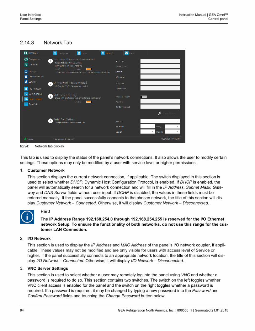
2.14.3 Network Tab
fig.94: Network tab display
This tab is used to display the status of the panel’s network connections. It also allows the user to modify certainsettings. These options may only be modified by a user with service level or higher permissions.
1. Customer NetworkThis section displays the current network connection, if applicable. The switch displayed in this section isused to select whether DHCP, Dynamic Host Configuration Protocol, is enabled. If DHCP is enabled, thepanel will automatically search for a network connection and will fill in the IP Address, Subnet Mask, Gate-way and DNS Server fields without user input. If DCHP is disabled, the values in these fields must beentered manually. If the panel successfully connects to the chosen network, the title of this section will dis-play Customer Network – Connected. Otherwise, it will display Customer Network – Disconnected.
Hint!
The IP Address Range 192.168.254.0 through 192.168.254.255 is reserved for the I/O Ethernetnetwork Setup. To ensure the functionality of both networks, do not use this range for the cus-tomer LAN Connection.
2. I/O NetworkThis section is used to display the IP Address and MAC Address of the panel’s I/O network coupler, if appli-cable. These values may not be modified and are only visible for users with access level of Service orhigher. If the panel successfully connects to an appropriate network location, the title of this section will dis-play I/O Network – Connected. Otherwise, it will display I/O Network – Disconnected.
3. VNC Server SettingsThis section is used to select whether a user may remotely log into the panel using VNC and whether apassword is required to do so. This section contains two switches. The switch on the left toggles whetherVNC client access is enabled for the panel and the switch on the right toggles whether a password isrequired. If a password is required, it may be changed by typing a new password into the Password andConfirm Password fields and touching the Change Password button below.
User interfacePanel Settings
Instruction Manual | GEA Omni™Control panel
94 GEA Refrigeration North America, Inc. | 806550_1 | Generated 21.01.2015
4. Serial Port SettingsThis section allows the user to modify the serial communication settings of the panel. The available protocolsare Motor Starter Communication, Modbus RTU and Allen Bradley DF1. Five additional drop down lists areprovided which allow the user to select the Baud Rate, Parity, Data Bit, Stop Bit and Node Number for thecommunication.
Hint!
The Motor Starter Communication protocol is only available if it has been enabled in the con-figuration.
Instruction Manual | GEA Omni™Control panel
User interfacePanel Settings
GEA Refrigeration North America, Inc. | 806550_1 | Generated 21.01.2015 95
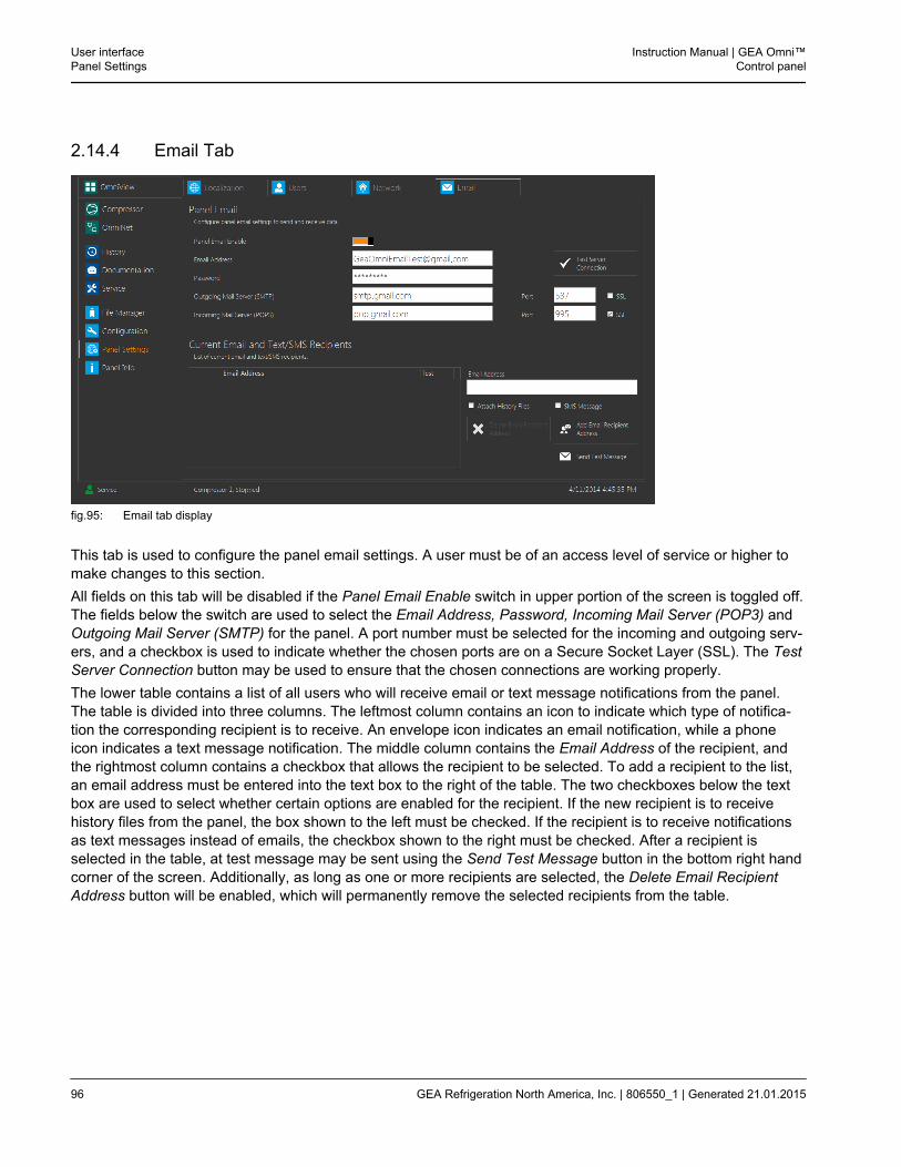
2.14.4 Email Tab
fig.95: Email tab display
This tab is used to configure the panel email settings. A user must be of an access level of service or higher tomake changes to this section.All fields on this tab will be disabled if the Panel Email Enable switch in upper portion of the screen is toggled off.The fields below the switch are used to select the Email Address, Password, Incoming Mail Server (POP3) andOutgoing Mail Server (SMTP) for the panel. A port number must be selected for the incoming and outgoing serv-ers, and a checkbox is used to indicate whether the chosen ports are on a Secure Socket Layer (SSL). The TestServer Connection button may be used to ensure that the chosen connections are working properly.The lower table contains a list of all users who will receive email or text message notifications from the panel.The table is divided into three columns. The leftmost column contains an icon to indicate which type of notifica-tion the corresponding recipient is to receive. An envelope icon indicates an email notification, while a phoneicon indicates a text message notification. The middle column contains the Email Address of the recipient, andthe rightmost column contains a checkbox that allows the recipient to be selected. To add a recipient to the list,an email address must be entered into the text box to the right of the table. The two checkboxes below the textbox are used to select whether certain options are enabled for the recipient. If the new recipient is to receivehistory files from the panel, the box shown to the left must be checked. If the recipient is to receive notificationsas text messages instead of emails, the checkbox shown to the right must be checked. After a recipient isselected in the table, at test message may be sent using the Send Test Message button in the bottom right handcorner of the screen. Additionally, as long as one or more recipients are selected, the Delete Email RecipientAddress button will be enabled, which will permanently remove the selected recipients from the table.
User interfacePanel Settings
Instruction Manual | GEA Omni™Control panel
96 GEA Refrigeration North America, Inc. | 806550_1 | Generated 21.01.2015
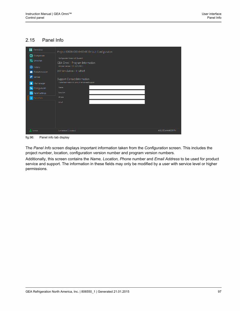
2.15 Panel Info
fig.96: Panel info tab display
The Panel Info screen displays important information taken from the Configuration screen. This includes theproject number, location, configuration version number and program version numbers.Additionally, this screen contains the Name, Location, Phone number and Email Address to be used for productservice and support. The information in these fields may only be modified by a user with service level or higherpermissions.
Instruction Manual | GEA Omni™Control panel
User interfacePanel Info
GEA Refrigeration North America, Inc. | 806550_1 | Generated 21.01.2015 97
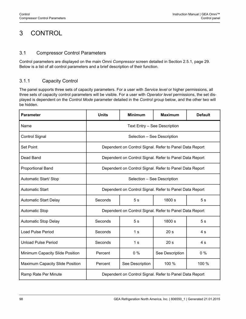
3 CONTROL
3.1 Compressor Control Parameters
Control parameters are displayed on the main Omni Compressor screen detailed in Section 2.5.1, page 29.Below is a list of all control parameters and a brief description of their function.
3.1.1 Capacity Control
The panel supports three sets of capacity parameters. For a user with Service level or higher permissions, allthree sets of capacity control parameters will be visible. For a user with Operator level permissions, the set dis-played is dependent on the Control Mode parameter detailed in the Control group below, and the other two willbe hidden.
Parameter Units Minimum Maximum Default
Name Text Entry – See Description
Control Signal Selection – See Description
Set Point Dependent on Control Signal. Refer to Panel Data Report
Dead Band Dependent on Control Signal. Refer to Panel Data Report
Proportional Band Dependent on Control Signal. Refer to Panel Data Report
Automatic Start/ Stop Selection – See Description
Automatic Start Dependent on Control Signal. Refer to Panel Data Report
Automatic Start Delay Seconds 5 s 1800 s 5 s
Automatic Stop Dependent on Control Signal. Refer to Panel Data Report
Automatic Stop Delay Seconds 5 s 1800 s 5 s
Load Pulse Period Seconds 1 s 20 s 4 s
Unload Pulse Period Seconds 1 s 20 s 4 s
Minimum Capacity Slide Position Percent 0 % See Description 0 %
Maximum Capacity Slide Position Percent See Description 100 % 100 %
Ramp Rate Per Minute Dependent on Control Signal. Refer to Panel Data Report
ControlCompressor Control Parameters
Instruction Manual | GEA Omni™Control panel
98 GEA Refrigeration North America, Inc. | 806550_1 | Generated 21.01.2015
1. NameThis parameter contains the name used to identify the specific set of capacity control parameters. The usermay modify it by entering a desired text string into this parameter.
2. Control SignalThis parameter is used to set which input will be monitored to control the capacity slide valve of the com-pressor. The options are:
• Suction Pressure
• Suction Pressure as Temperature
• Inlet Temperature
• Outlet Temperature
• Discharge Pressure
• Discharge Pressure as Temperature
• Remote Capacity Slide
• Remote Temperature
• Remote Pressure
Hint!
If this parameter is changed to an option with a different unit type, the Set point, Dead Bandand Proportional Band will be reset to their default values.
3. Set PointThis parameter is used to choose the desired value at which the compressor will attempt to maintain thecontrol signal. The user may change this parameter by entering a new value with the keypad. The maximumvalue, minimum value and units of the parameter are dependent on the chosen control signal:
• PressureMeasured in the panel pressure units as selected in the Panel Settings screen.
• TemperatureMeasured in the panel temperature units as selected in the Panel Settings screen.
• Remote Capacity SlideMeasured in percent.
4. Dead BandThis parameter is used to define a range above and below the set point within which no capacity controladjustments will be made. This functionality is illustrated in Figure 107, page 169. The maximum value, min-imum value and units of the parameter are dependent on the chosen control signal:
• PressureMeasured in the panel pressure units as selected in the Panel Settings screen.
• TemperatureMeasured in the panel temperature units as selected in the Panel Settings screen.
• Remote Capacity SlideMeasured in percent.
Instruction Manual | GEA Omni™Control panel
ControlCompressor Control Parameters
GEA Refrigeration North America, Inc. | 806550_1 | Generated 21.01.2015 99
5. Proportional BandThis parameter is used to define a range above and below the set point within which the width of thecapacity control pulses is reduced to avoid overshooting or undershooting the set point. This functionality isillustrated in Figure 107, page 169. The maximum value, minimum value and units of the parameter aredependent on the chosen control signal:
• PressureMeasured in the panel pressure units as selected in the Panel Settings screen.
• TemperatureMeasured in the panel temperature units as selected in the Panel Settings screen.
• Remote Capacity SlideMeasured in percent.
6. Automatic Start StopThis parameter is used to select whether the panel is permitted to run and stop the compressor automaticallyto maintain the control signal. While the parameter is set to Enabled, an A will appear in the upper left handcorner of the Start button.
7. Automatic StartThis parameter is used to select the control signal value at which the compressor will attempt to start. Thisparameter is only visible if the Automatic Start Stop parameter is set to Enabled. The maximum value, mini-mum value and units of the parameter are dependent on the chosen Control Signal:
• PressureMeasured in the panel pressure units as selected in the Panel Settings screen.
• TemperatureMeasured in the panel temperature units as selected in the Panel Settings screen.
• Remote Capacity SlideMeasured in percent.
8. Automatic Start DelayThis parameter is used to select the period of time that must elapse after the conditions to automatically startthe compressor are met before it will be permitted to start. In most circumstances the control signal mustexceed the value of the Automatic Start parameter. The exception is when the control signal is set to Dis-charge Pressure, where the value must instead remain below the Automatic Start parameter. This parameteris only visible if the Automatic Start Stop parameter is set to Enabled. The value is measured in seconds.
9. Automatic StopThis parameter is used to select the control signal value at which the compressor will stop. This parameter isonly visible if the Automatic Start Stop parameter is set to Enabled. The maximum value, minimum value andunits of the parameter are dependent on the chosen control signal:
• PressureMeasured in the panel pressure units as selected in the Panel Settings screen.
• TemperatureMeasured in the panel temperature units as selected in the Panel Settings screen.
• Remote Capacity SlideMeasured in percent.
ControlCompressor Control Parameters
Instruction Manual | GEA Omni™Control panel
100 GEA Refrigeration North America, Inc. | 806550_1 | Generated 21.01.2015
10. Automatic Stop DelayThis parameter is used to select the period of time that must elapse after the conditions to automatically stopthe compressor are met before it will be permitted to start. In most circumstances the control signal mustremain below the value of the Automatic Start parameter. The exception is when the control signal is set toDischarge Pressure, where the value must instead exceed the Automatic Start parameter. This parameter isonly visible if the Automatic Start Stop parameter is set to Enabled. The value is measured in seconds.
11. Load Pulse PeriodThis parameter is used to select the period of time that will elapse between the start of pulse signals whilethe compressor is loading and the control signal is within the range defined by the proportional band. Theproximity of the control signal value to the set point determines for which portion of the period the compres-sor will be loading. The value is measured in seconds.
12. Unload Pulse PeriodThis parameter is used to select the period of time that will elapse between the start of pulse signals whilethe compressor is unloading and the control signal is within the range defined by the proportional band. Theproximity of the control signal value to the set point determines for which portion of the period the compres-sor will be unloading. The value is measured in seconds.
13. Minimum Capacity Slide PositionThis parameter is used to select the lowest allowable value for the capacity slide valve during normal opera-tion. If the value drops below this value, the compressor will load until the minimum position is reachedunless an outside limitation is active. The maximum value of this parameter is the current value of the Maxi-mum Capacity Slide Position parameter. The parameter may only be manually changed from the panel whileit is operating in Local mode. If the panel is operating in remote mode, changes to this value must be madethrough the sequence control. The value is measured in percent.
14. Maximum Capacity Slide PositionThis parameter is used to select the highest allowable value for the capacity slide valve during normal opera-tion. If the value rises above this value, the compressor will unload until the maximum position is reachedunless an outside limitation is active. The minimum value of this parameter is the current value of the Mini-mum Capacity Slide Position parameter. The value is measured in percent.
15. Ramp Rate per MinuteThis parameter is used to select how quickly the set point approaches its chosen value after startup. Thevalue indicates the change per minute, and the maximum value, minimum value and units of the parameterare dependent on the chosen control signal:
• PressureMeasured in the panel pressure units as selected in the Panel Settings screen.
• TemperatureMeasured in the panel temperature units as selected in the Panel Settings screen.
• Remote Capacity SlideMeasured in percent.
Instruction Manual | GEA Omni™Control panel
ControlCompressor Control Parameters
GEA Refrigeration North America, Inc. | 806550_1 | Generated 21.01.2015 101
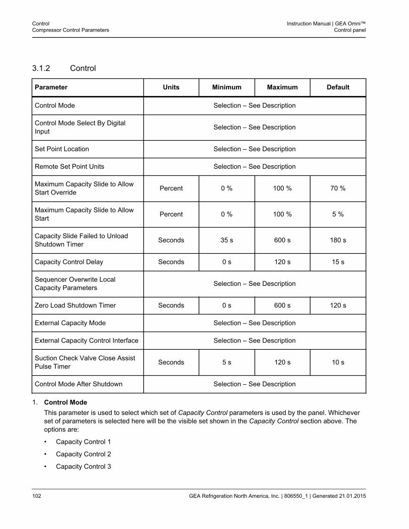
3.1.2 Control
Parameter Units Minimum Maximum Default
Control Mode Selection – See Description
Control Mode Select By DigitalInput Selection – See Description
Set Point Location Selection – See Description
Remote Set Point Units Selection – See Description
Maximum Capacity Slide to AllowStart Override Percent 0 % 100 % 70 %
Maximum Capacity Slide to AllowStart Percent 0 % 100 % 5 %
Capacity Slide Failed to UnloadShutdown Timer Seconds 35 s 600 s 180 s
Capacity Control Delay Seconds 0 s 120 s 15 s
Sequencer Overwrite LocalCapacity Parameters Selection – See Description
Zero Load Shutdown Timer Seconds 0 s 600 s 120 s
External Capacity Mode Selection – See Description
External Capacity Control Interface Selection – See Description
Suction Check Valve Close AssistPulse Timer Seconds 5 s 120 s 10 s
Control Mode After Shutdown Selection – See Description
1. Control ModeThis parameter is used to select which set of Capacity Control parameters is used by the panel. Whicheverset of parameters is selected here will be the visible set shown in the Capacity Control section above. Theoptions are:
• Capacity Control 1
• Capacity Control 2
• Capacity Control 3
ControlCompressor Control Parameters
Instruction Manual | GEA Omni™Control panel
102 GEA Refrigeration North America, Inc. | 806550_1 | Generated 21.01.2015
2. Control Mode Select By Digital InputThis parameter is used to select whether the capacity control mode is selected using a parameter or a DigitalInput point. If a Digital Input point is used, the compressor will be limited to Capacity Control 1 on a de-ener-gized signal, and Capacity Control 2 on an energized signal. The parameter will only be visible if the SetPoint Selection Digital Input option is enabled in the panel configuration. The options are:
• Enabled
• Disabled
3. Set Point LocationThis parameter is used to select whether the capacity control set point is taken from the selected set ofCapacity Control parameters or from a Remote device. The options are:
• Local
• Remote
4. Remote Set Point UnitsThis parameter is used to select the units of measurement that will be used for remote set point control. Theparameter will only be visible if the Remote Set Point option is enabled in the panel configuration. Theoptions are:
• Pressure
• Temperature
• Slide Valve
5. Maximum Capacity Slide To Allow Start OverrideFor GEA Grasso Small and Medium compressors, if the compressor capacity slide position remains abovethe Maximum Capacity Slide To Allow Start parameter during the period of time dictated by the Oil PumpCompressor Allowed Start Timer, the panel will compare the slide position to this value. If the capacity slideposition is greater than this value for the duration of the Capacity Slide Failed to Unload Shutdown Timer, ashutdown will be issued. The value is measured in percent.
6. Maximum Capacity Slide To Allow StartThis parameter is used to select the maximum allowable position of the capacity slide when the compressoris instructed to start. If the capacity slide position is above this parameter when a start signal is received, thecompressor will unload until the slide position has dropped below the parameter before allowing the com-pressor to start. The compressor will also unload to this position after the compressor is stopped. The valueis measured in percent.
7. Capacity Slide Failed to Unload Shutdown TimerThis parameter is used to select the amount of time the panel will wait for the compressor to unload, eitherbefore starting or after stopping, before a Capacity Slide Failed to Unload Shutdown will be annunciated.The value is measured in seconds.
8. Capacity Control DelayThis parameter is used to select the period of time that will elapse between the compressor starting andcapacity control being enabled. The value is measured in seconds.
9. Sequencer Overwrite Local Capacity ParametersThis parameter is used to select whether the local capacity control parameters may be overwritten by param-eters from an external sequencer.
Instruction Manual | GEA Omni™Control panel
ControlCompressor Control Parameters
GEA Refrigeration North America, Inc. | 806550_1 | Generated 21.01.2015 103
10. Zero Load Shutdown TimerThis parameter is used to select the period of time that the capacity slide position may remain at the zeroload percentage before a shutdown condition will be annunciated. The value is measured in seconds.
11. External Capacity ModeThis parameter is used to determines if the external capacity exerts direct control over the load/unload sole-noids or simply communicates the need for increased or decreased capacity to the compressor. The optionsare:
• Direct Pulse Control
• Indirect Pulse Control
12. External Capacity Control Mode InterfaceThis parameter is used to select the method of communication used between the panel and any remotecapacity control devices. The options are:
• Network
• Hard Wired
13. Suction Check Valve Close Assist Pulse TimerThis parameter is used to select the length of the control pulses used to operate close assist feature of themotorized suction check valve. The parameter will only be visible if the Suction Check Valve Close Assistoption in the compressor configuration is set to Normally Open Pulsed. The value is measured in seconds.
14. Control Mode After ShutdownThis parameter is used to select whether the compressor will be permitted to resume operation in remotemode following a shutdown condition. The options are:
• Enabled
• Disabled
ControlCompressor Control Parameters
Instruction Manual | GEA Omni™Control panel
104 GEA Refrigeration North America, Inc. | 806550_1 | Generated 21.01.2015
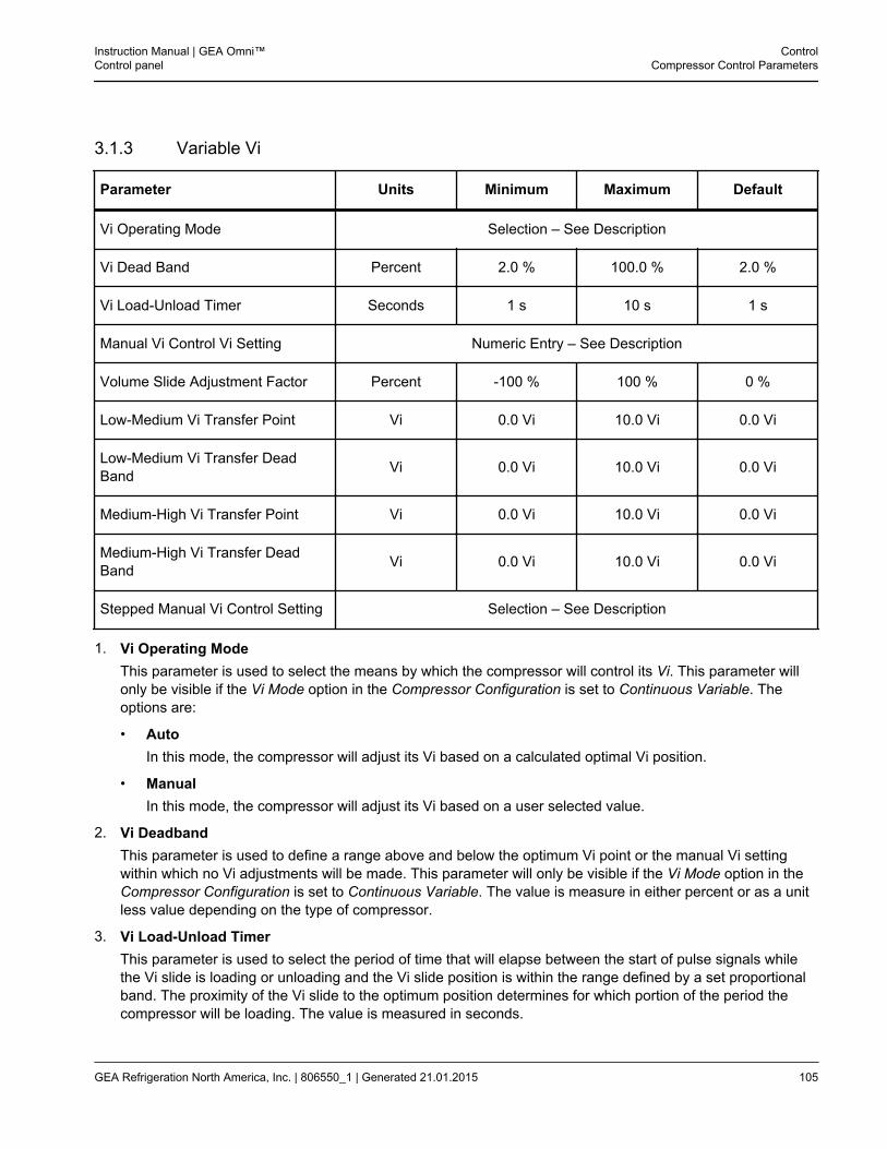
3.1.3 Variable Vi
Parameter Units Minimum Maximum Default
Vi Operating Mode Selection – See Description
Vi Dead Band Percent 2.0 % 100.0 % 2.0 %
Vi Load-Unload Timer Seconds 1 s 10 s 1 s
Manual Vi Control Vi Setting Numeric Entry – See Description
Volume Slide Adjustment Factor Percent -100 % 100 % 0 %
Low-Medium Vi Transfer Point Vi 0.0 Vi 10.0 Vi 0.0 Vi
Low-Medium Vi Transfer DeadBand Vi 0.0 Vi 10.0 Vi 0.0 Vi
Medium-High Vi Transfer Point Vi 0.0 Vi 10.0 Vi 0.0 Vi
Medium-High Vi Transfer DeadBand Vi 0.0 Vi 10.0 Vi 0.0 Vi
Stepped Manual Vi Control Setting Selection – See Description
1. Vi Operating ModeThis parameter is used to select the means by which the compressor will control its Vi. This parameter willonly be visible if the Vi Mode option in the Compressor Configuration is set to Continuous Variable. Theoptions are:
• AutoIn this mode, the compressor will adjust its Vi based on a calculated optimal Vi position.
• ManualIn this mode, the compressor will adjust its Vi based on a user selected value.
2. Vi DeadbandThis parameter is used to define a range above and below the optimum Vi point or the manual Vi settingwithin which no Vi adjustments will be made. This parameter will only be visible if the Vi Mode option in theCompressor Configuration is set to Continuous Variable. The value is measure in either percent or as a unitless value depending on the type of compressor.
3. Vi Load-Unload TimerThis parameter is used to select the period of time that will elapse between the start of pulse signals whilethe Vi slide is loading or unloading and the Vi slide position is within the range defined by a set proportionalband. The proximity of the Vi slide to the optimum position determines for which portion of the period thecompressor will be loading. The value is measured in seconds.
Instruction Manual | GEA Omni™Control panel
ControlCompressor Control Parameters
GEA Refrigeration North America, Inc. | 806550_1 | Generated 21.01.2015 105
4. Manual Control Vi SettingThis parameter is used to select the desired Vi value during manual operation. This parameter will only bevisible if the Vi Mode option in the Compressor Configuration is set to Continuous Variable and the Vi Opera-tion Mode parameter is set to Manual. The value is unit less.
5. Volume Slide Adjustment FactorThis parameter is used to select the amount that the volume slide must deviate from the point where theoptimum position was last calculated before the calculations will be reevaluated. This parameter will only bevisible if the Vi Mode option in the compressor configuration is set to Continuous Variable and if the com-pressor brand is set to Vilter. The value is measure in percent.
6. Low-Medium Vi Transfer PointThis parameter is used to select the point where the current Vi step will switch between Low and Medium.The parameter will only be visible if the Vi Mode is set to Step Variable in the compressor configuration. Thevalue is measured in Vi.
7. Low-Medium Vi Transfer Dead BandThis parameter is used to select the range above and below the Low-Medium Transfer Point within which noVi step changes will occur. If the Vi reading rises above this range while the current step is Low the Vi stepwill transfer to Medium, and if it falls below the range while the current step is Medium the Vi step will trans-fer to Low. The value is measured in Vi.
8. Medium-High Vi Transfer PointThis parameter is used to select the point where the current Vi step will switch between Medium and High.The parameter will only be visible if the Vi Mode is set to Step Variable in the compressor configuration. Thevalue is measured in Vi.
9. Medium-High Vi Transfer Dead BandThis parameter is used to select the range above and below the Medium-High Transfer Point within which noVi step changes will occur. If the Vi reading rises above this range while the current step is Medium the Vistep will transfer to High, and if it falls below the range while the current step is High the Vi step will transferto Medium. The value is measured in Vi.
10. Stepped Manual Vi Control SettingThis parameter is used to manually set the current Vi Setting for the compressor. The parameter will only bevisible if the Vi Mode is set to Step Variable in the compressor configuration. The options are:
• Low
• Medium
• High
3.1.4 Motor
Parameter Units Minimum Maximum Default
Accumulated Runtime Hours Hours 0.0 h 1.0 x 10⁹ h 0.0 h
Motor Start to Start Delay Minutes 0.0 min 9999.0 min 20.0 min
ControlCompressor Control Parameters
Instruction Manual | GEA Omni™Control panel
106 GEA Refrigeration North America, Inc. | 806550_1 | Generated 21.01.2015
Parameter Units Minimum Maximum Default
Motor Stop to Start Delay Seconds 1 s 60 s 5 s
Motor Bypass Configuration Selection – See Description
Motor Bypass Configuration ByDigital Input Selection – See Description
1. Accumulated Runtime HoursThis parameter displays the total amount of time the motor has been in the run state. It may also be changedmanually. The value is measured in hours.
2. Motor Start To Start DelayThis parameter is used to select the period of time that must elapse after the motor starts before it will bepermitted to start again. The value is measured in minutes.
3. Motor Stop To Start DelayThis parameter is used to select the period of time that must elapse after the motor has stopped before it willbe permitted to start again. The value is measured in seconds.
4. Motor Bypass ConfigurationThis parameter is used to select the whether the motor will operate as a variable speed or fixed speed motorwhile it is operating in bypass mode. The parameter is only visible if the motor type is set to Variable Speedwith Bypass in the configuration and the Motor Bypass Configuration by Digital Input parameter is currentlyset to Disabled. The options are:
• Fixed Speed
• Variable Speed
5. Motor Bypass Configuration By Digital InputThis parameter is used to select whether the operating mode of the motor bypass is controlled by a digitalinput. The parameter is only visible if the motor type is set to Variable Speed with Bypass in the configura-tion. The options are:
• Disabled
• Enabled
3.1.5 Motor Power
Parameter Units Minimum Maximum Default
kW Demand Metering Ratio kW 0.0 kW 3200.0 KW 0.0 kW
kWh Input Pulse Weight
kWh Estimated Usage kWh 0.0 kWh 10 x 109 kWh 0.0 kWh
Instruction Manual | GEA Omni™Control panel
ControlCompressor Control Parameters
GEA Refrigeration North America, Inc. | 806550_1 | Generated 21.01.2015 107
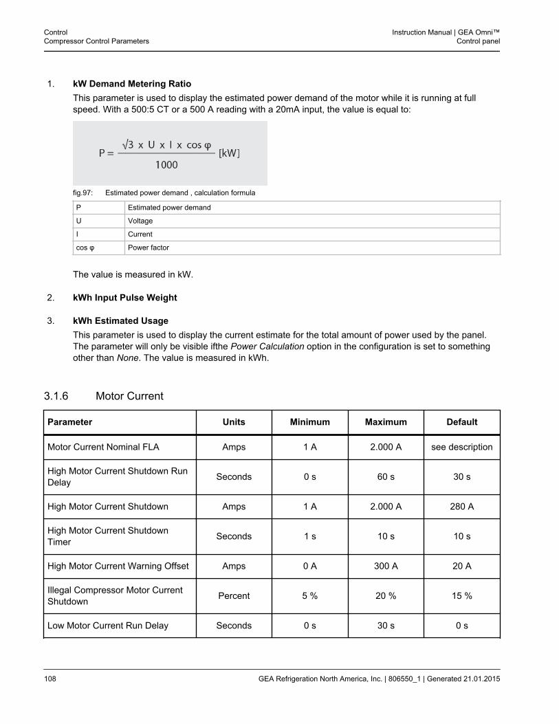
1. kW Demand Metering RatioThis parameter is used to display the estimated power demand of the motor while it is running at fullspeed. With a 500:5 CT or a 500 A reading with a 20mA input, the value is equal to:
fig.97: Estimated power demand , calculation formula
P Estimated power demand
U Voltage
I Current
cos φ Power factor
The value is measured in kW.
2. kWh Input Pulse Weight
3. kWh Estimated UsageThis parameter is used to display the current estimate for the total amount of power used by the panel.The parameter will only be visible ifthe Power Calculation option in the configuration is set to somethingother than None. The value is measured in kWh.
3.1.6 Motor Current
Parameter Units Minimum Maximum Default
Motor Current Nominal FLA Amps 1 A 2.000 A see description
High Motor Current Shutdown RunDelay Seconds 0 s 60 s 30 s
High Motor Current Shutdown Amps 1 A 2.000 A 280 A
High Motor Current ShutdownTimer Seconds 1 s 10 s 10 s
High Motor Current Warning Offset Amps 0 A 300 A 20 A
Illegal Compressor Motor CurrentShutdown Percent 5 % 20 % 15 %
Low Motor Current Run Delay Seconds 0 s 30 s 0 s
ControlCompressor Control Parameters
Instruction Manual | GEA Omni™Control panel
108 GEA Refrigeration North America, Inc. | 806550_1 | Generated 21.01.2015
Parameter Units Minimum Maximum Default
Low Motor Current Shutdown Amps 0 A 235 A 10 A
Low Motor Current Shutdown Timer Seconds 0 s 30 s 8 s
Limitation Motor Current LoadInhibit Offset Amps 0 A 300 A 15 A
Limitation Motor Current ForceUnload Offset Amps 0 A 300 A 10 A
1. Motor Current Nominal FLAThis parameter is used to select the Full Load Amps (FLA) value of the motor. This value may be found onthe nameplate of the motor. The value is measured in amps.
2. High Motor Current Shutdown Run DelayThis parameter is used to select a period of time after the compressor is started during which the high motorcurrent safeties will be ignored. The value is measured in seconds.
3. High Motor Current ShutdownThis parameter is used to select the motor current above which a High Motor Current Shutdown will beannunciated. The value is measured in amps.
4. High Motor Current Shutdown TimerThis parameter is used to select the amount of time that the motor current must exceed the High Motor Cur-rent Shutdown value before a High Motor Current Shutdown will be annunciated. The value is measured inseconds.
5. High Motor Current Warning OffsetThis parameter is used to set an offset value subtracted from the value of the High Motor Current Shutdownparameter. If the motor current exceeds this calculated value, a High Motor Current Warning will be annunci-ated. The value is measured in amps.
6. Illegal Compressor Motor Current ShutdownThis parameter is used to select the maximum percentage of the FLA that motor current may reach while themotor starter is not energized. If this value is exceeded while the motor starter is still de-energized, an IllegalCompressor Motor Current Shutdown will be annunciated. The value is measured in percent.
7. Low Motor Current Run DelayThis parameter is used to select a period of time after the compressor is started during which the low motorcurrent safeties will be ignored. The value is measured in seconds.
8. Low Motor Current ShutdownThis parameter is used to select the set point for the Low Motor Current Shutdown. If the motor current fallsbelow this value for a user defined period of time, a Low Motor Current Shutdown will be annunciated. Thevalue is measured in amps.
Instruction Manual | GEA Omni™Control panel
ControlCompressor Control Parameters
GEA Refrigeration North America, Inc. | 806550_1 | Generated 21.01.2015 109
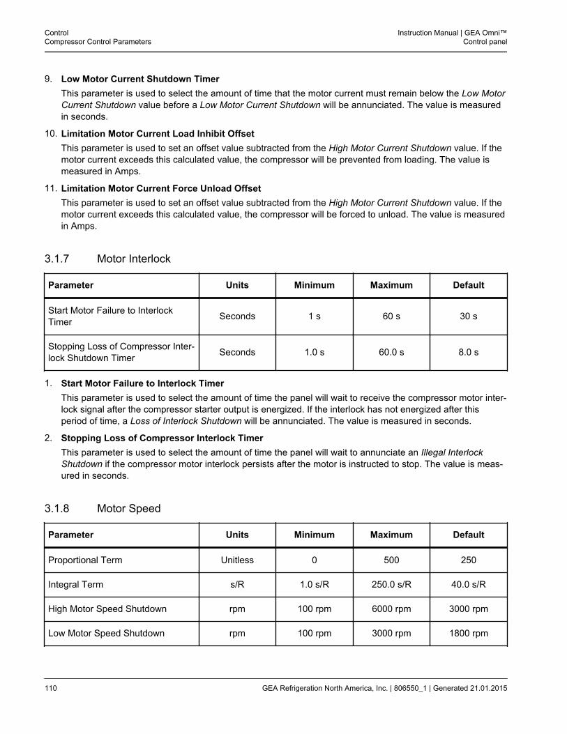
9. Low Motor Current Shutdown TimerThis parameter is used to select the amount of time that the motor current must remain below the Low MotorCurrent Shutdown value before a Low Motor Current Shutdown will be annunciated. The value is measuredin seconds.
10. Limitation Motor Current Load Inhibit OffsetThis parameter is used to set an offset value subtracted from the High Motor Current Shutdown value. If themotor current exceeds this calculated value, the compressor will be prevented from loading. The value ismeasured in Amps.
11. Limitation Motor Current Force Unload OffsetThis parameter is used to set an offset value subtracted from the High Motor Current Shutdown value. If themotor current exceeds this calculated value, the compressor will be forced to unload. The value is measuredin Amps.
3.1.7 Motor Interlock
Parameter Units Minimum Maximum Default
Start Motor Failure to InterlockTimer Seconds 1 s 60 s 30 s
Stopping Loss of Compressor Inter-lock Shutdown Timer Seconds 1.0 s 60.0 s 8.0 s
1. Start Motor Failure to Interlock TimerThis parameter is used to select the amount of time the panel will wait to receive the compressor motor inter-lock signal after the compressor starter output is energized. If the interlock has not energized after thisperiod of time, a Loss of Interlock Shutdown will be annunciated. The value is measured in seconds.
2. Stopping Loss of Compressor Interlock TimerThis parameter is used to select the amount of time the panel will wait to annunciate an Illegal InterlockShutdown if the compressor motor interlock persists after the motor is instructed to stop. The value is meas-ured in seconds.
3.1.8 Motor Speed
Parameter Units Minimum Maximum Default
Proportional Term Unitless 0 500 250
Integral Term s/R 1.0 s/R 250.0 s/R 40.0 s/R
High Motor Speed Shutdown rpm 100 rpm 6000 rpm 3000 rpm
Low Motor Speed Shutdown rpm 100 rpm 3000 rpm 1800 rpm
ControlCompressor Control Parameters
Instruction Manual | GEA Omni™Control panel
110 GEA Refrigeration North America, Inc. | 806550_1 | Generated 21.01.2015
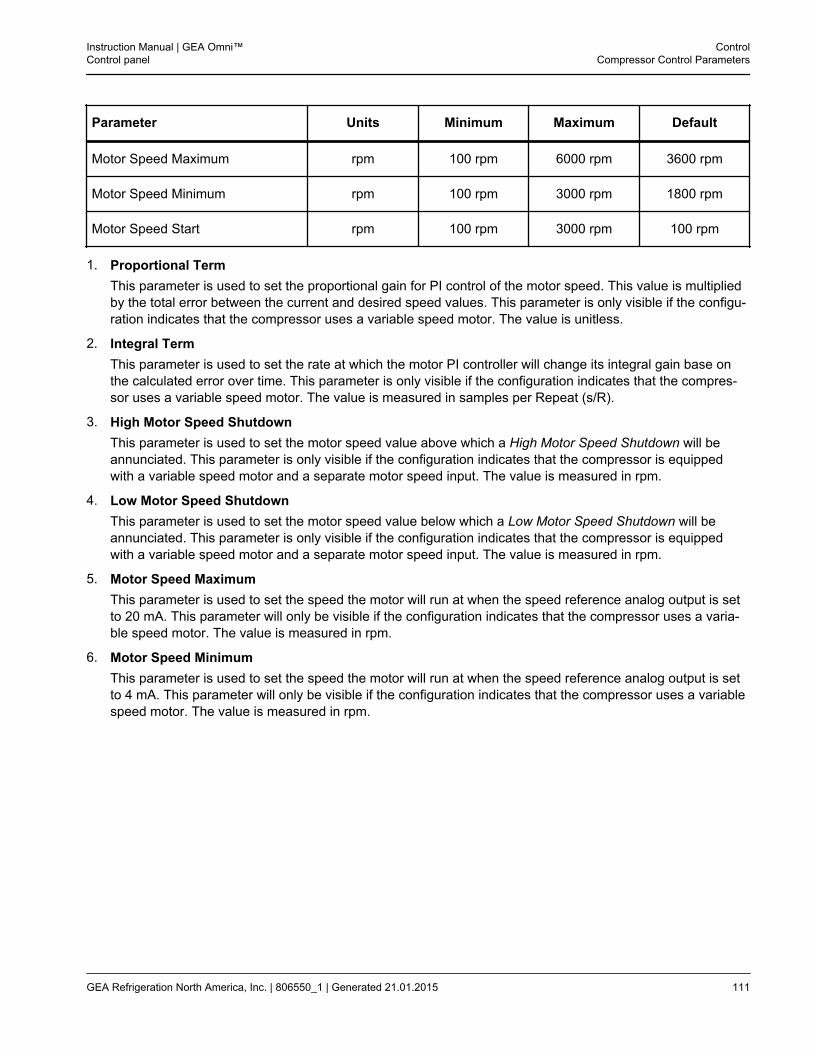
Parameter Units Minimum Maximum Default
Motor Speed Maximum rpm 100 rpm 6000 rpm 3600 rpm
Motor Speed Minimum rpm 100 rpm 3000 rpm 1800 rpm
Motor Speed Start rpm 100 rpm 3000 rpm 100 rpm
1. Proportional TermThis parameter is used to set the proportional gain for PI control of the motor speed. This value is multipliedby the total error between the current and desired speed values. This parameter is only visible if the configu-ration indicates that the compressor uses a variable speed motor. The value is unitless.
2. Integral TermThis parameter is used to set the rate at which the motor PI controller will change its integral gain base onthe calculated error over time. This parameter is only visible if the configuration indicates that the compres-sor uses a variable speed motor. The value is measured in samples per Repeat (s/R).
3. High Motor Speed ShutdownThis parameter is used to set the motor speed value above which a High Motor Speed Shutdown will beannunciated. This parameter is only visible if the configuration indicates that the compressor is equippedwith a variable speed motor and a separate motor speed input. The value is measured in rpm.
4. Low Motor Speed ShutdownThis parameter is used to set the motor speed value below which a Low Motor Speed Shutdown will beannunciated. This parameter is only visible if the configuration indicates that the compressor is equippedwith a variable speed motor and a separate motor speed input. The value is measured in rpm.
5. Motor Speed MaximumThis parameter is used to set the speed the motor will run at when the speed reference analog output is setto 20 mA. This parameter will only be visible if the configuration indicates that the compressor uses a varia-ble speed motor. The value is measured in rpm.
6. Motor Speed MinimumThis parameter is used to set the speed the motor will run at when the speed reference analog output is setto 4 mA. This parameter will only be visible if the configuration indicates that the compressor uses a variablespeed motor. The value is measured in rpm.
Instruction Manual | GEA Omni™Control panel
ControlCompressor Control Parameters
GEA Refrigeration North America, Inc. | 806550_1 | Generated 21.01.2015 111
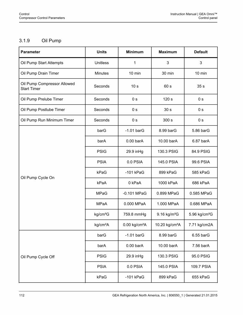
3.1.9 Oil Pump
Parameter Units Minimum Maximum Default
Oil Pump Start Attempts Unitless 1 3 3
Oil Pump Drain Timer Minutes 10 min 30 min 10 min
Oil Pump Compressor AllowedStart Timer Seconds 10 s 60 s 35 s
Oil Pump Prelube Timer Seconds 0 s 120 s 0 s
Oil Pump Postlube Timer Seconds 0 s 30 s 0 s
Oil Pump Run Minimum Timer Seconds 0 s 300 s 0 s
Oil Pump Cycle On
barG -1.01 barG 8.99 barG 5.86 barG
barA 0.00 barA 10.00 barA 6.87 barA
PSIG 29.9 inHg 130.3 PSIG 84.9 PSIG
PSIA 0.0 PSIA 145.0 PSIA 99.6 PSIA
kPaG -101 kPaG 899 kPaG 585 kPaG
kPaA 0 kPaA 1000 kPaA 686 kPaA
MPaG -0.101 MPaG 0.899 MPaG 0.585 MPaG
MPaA 0.000 MPaA 1.000 MPaA 0.686 MPaA
kg/cm²G 759.8 mmHg 9.16 kg/m²G 5.96 kg/cm²G
kg/cm²A 0.00 kg/cm²A 10.20 kg/cm²A 7.71 kg/cm2A
Oil Pump Cycle Off
barG -1.01 barG 8.99 barG 6.55 barG
barA 0.00 barA 10.00 barA 7.56 barA
PSIG 29.9 inHg 130.3 PSIG 95.0 PSIG
PSIA 0.0 PSIA 145.0 PSIA 109.7 PSIA
kPaG -101 kPaG 899 kPaG 655 kPaG
ControlCompressor Control Parameters
Instruction Manual | GEA Omni™Control panel
112 GEA Refrigeration North America, Inc. | 806550_1 | Generated 21.01.2015
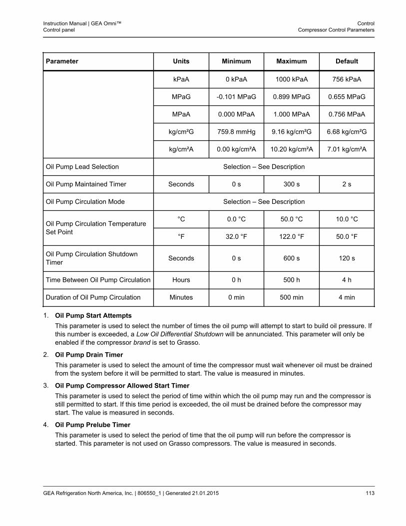
Parameter Units Minimum Maximum Default
kPaA 0 kPaA 1000 kPaA 756 kPaA
MPaG -0.101 MPaG 0.899 MPaG 0.655 MPaG
MPaA 0.000 MPaA 1.000 MPaA 0.756 MPaA
kg/cm²G 759.8 mmHg 9.16 kg/cm²G 6.68 kg/cm²G
kg/cm²A 0.00 kg/cm²A 10.20 kg/cm²A 7.01 kg/cm²A
Oil Pump Lead Selection Selection – See Description
Oil Pump Maintained Timer Seconds 0 s 300 s 2 s
Oil Pump Circulation Mode Selection – See Description
Oil Pump Circulation TemperatureSet Point
°C 0.0 °C 50.0 °C 10.0 °C
°F 32.0 °F 122.0 °F 50.0 °F
Oil Pump Circulation ShutdownTimer Seconds 0 s 600 s 120 s
Time Between Oil Pump Circulation Hours 0 h 500 h 4 h
Duration of Oil Pump Circulation Minutes 0 min 500 min 4 min
1. Oil Pump Start AttemptsThis parameter is used to select the number of times the oil pump will attempt to start to build oil pressure. Ifthis number is exceeded, a Low Oil Differential Shutdown will be annunciated. This parameter will only beenabled if the compressor brand is set to Grasso.
2. Oil Pump Drain TimerThis parameter is used to select the amount of time the compressor must wait whenever oil must be drainedfrom the system before it will be permitted to start. The value is measured in minutes.
3. Oil Pump Compressor Allowed Start TimerThis parameter is used to select the period of time within which the oil pump may run and the compressor isstill permitted to start. If this time period is exceeded, the oil must be drained before the compressor maystart. The value is measured in seconds.
4. Oil Pump Prelube TimerThis parameter is used to select the period of time that the oil pump will run before the compressor isstarted. This parameter is not used on Grasso compressors. The value is measured in seconds.
Instruction Manual | GEA Omni™Control panel
ControlCompressor Control Parameters
GEA Refrigeration North America, Inc. | 806550_1 | Generated 21.01.2015 113

5. Oil Pump Postlube TimerThis parameter is used to select the period of time that the oil pump will remain running after the compressorhas stopped. This parameter is not used on Grasso compressors. The value is measured in seconds.
6. Oil Pump Run Minimum TimerThis parameter is used to select the minimum amount of time that the oil pump must run when it is startedbased on low differential pressure. It will only appear if the oil pump type is set to External Cycling in theconfiguration. The value is measured in seconds.
7. Oil Pump Cycle OnThis parameter is used to select the oil differential above which the oil pump will start. It will only appear ifthe oil pump type is set to External Cycling in the configuration. The value is measured in seconds.
8. Oil Pump Cycle OffThis parameter is used to select the oil differential below which the oil pump will stop after the time perioddefined by the Oil Pump Run Minimum Timer haselapsed. It will only appear if the oil pump type is set toExternal Cycling in the configuration. The value is measured in seconds.
9. Oil Pump Lead SelectionThis parameter is used to select whether Pump 1 or Pump 2 is considered the lead pump. This parameter isonly visible if the Dual Oil Pump option is selected in the Oil System Details section of the configuration. Theoptions are:
• Pump 1
• Pump 2
10. Oil Pump Maintained TimerThis parameter is used to select the period of time during startup that the oil pump must maintain a valid oildifferential pressure value before the compressor will be permitted to start. This parameter is fixed onGrasso compressors and will not be visible. The value is measured in seconds.
11. Oil Pump Circulation ModeThis parameter is used to select the mode of operation of the oil circulation system, if applicable. The optionsare:
• DisabledThis option indicates that the panel is not configured to control oil circulation.
• TemperatureThis option indicates that when the compressor is starting, the panel will check that the oil temperature isgreater than or equal to the value of the Oil Pump Circulation Temperature Set Point. If the oil tempera-ture does not meet this condition, the oil pump will run to attempt to bring the temperature reading up tothe appropriate value. If the temperature has not reached the selected value after a period of time speci-fied in the Oil Pump Circulation Shutdown Timer parameter, a shutdown will be annunciated.
• TimeThis option indicates that whenever the compressor is in the stopped state, the oil pump will periodicallyrun for a period of time determined in the Duration of Oil Pump Circulation parameter. The time that willelapse between circulation cycles is selected in the Time Between Oil Pump Circulation parameter.
ControlCompressor Control Parameters
Instruction Manual | GEA Omni™Control panel
114 GEA Refrigeration North America, Inc. | 806550_1 | Generated 21.01.2015
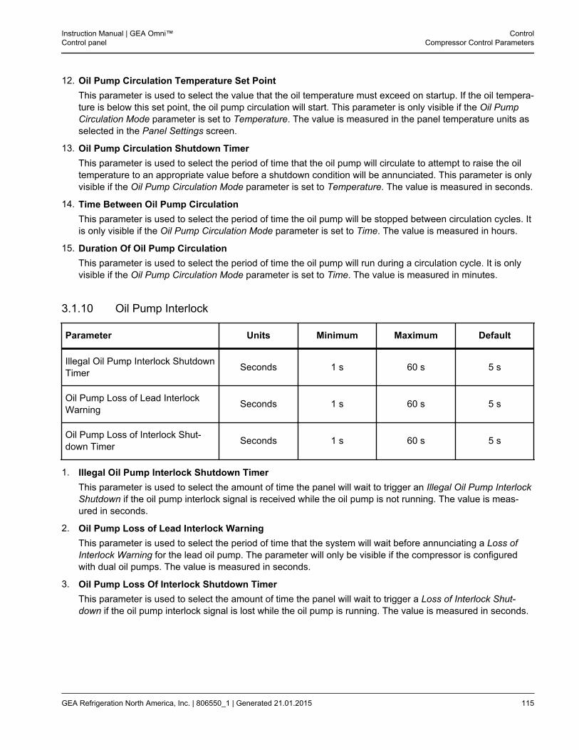
12. Oil Pump Circulation Temperature Set PointThis parameter is used to select the value that the oil temperature must exceed on startup. If the oil tempera-ture is below this set point, the oil pump circulation will start. This parameter is only visible if the Oil PumpCirculation Mode parameter is set to Temperature. The value is measured in the panel temperature units asselected in the Panel Settings screen.
13. Oil Pump Circulation Shutdown TimerThis parameter is used to select the period of time that the oil pump will circulate to attempt to raise the oiltemperature to an appropriate value before a shutdown condition will be annunciated. This parameter is onlyvisible if the Oil Pump Circulation Mode parameter is set to Temperature. The value is measured in seconds.
14. Time Between Oil Pump CirculationThis parameter is used to select the period of time the oil pump will be stopped between circulation cycles. Itis only visible if the Oil Pump Circulation Mode parameter is set to Time. The value is measured in hours.
15. Duration Of Oil Pump CirculationThis parameter is used to select the period of time the oil pump will run during a circulation cycle. It is onlyvisible if the Oil Pump Circulation Mode parameter is set to Time. The value is measured in minutes.
3.1.10 Oil Pump Interlock
Parameter Units Minimum Maximum Default
Illegal Oil Pump Interlock ShutdownTimer Seconds 1 s 60 s 5 s
Oil Pump Loss of Lead InterlockWarning Seconds 1 s 60 s 5 s
Oil Pump Loss of Interlock Shut-down Timer Seconds 1 s 60 s 5 s
1. Illegal Oil Pump Interlock Shutdown TimerThis parameter is used to select the amount of time the panel will wait to trigger an Illegal Oil Pump InterlockShutdown if the oil pump interlock signal is received while the oil pump is not running. The value is meas-ured in seconds.
2. Oil Pump Loss of Lead Interlock WarningThis parameter is used to select the period of time that the system will wait before annunciating a Loss ofInterlock Warning for the lead oil pump. The parameter will only be visible if the compressor is configuredwith dual oil pumps. The value is measured in seconds.
3. Oil Pump Loss Of Interlock Shutdown TimerThis parameter is used to select the amount of time the panel will wait to trigger a Loss of Interlock Shut-down if the oil pump interlock signal is lost while the oil pump is running. The value is measured in seconds.
Instruction Manual | GEA Omni™Control panel
ControlCompressor Control Parameters
GEA Refrigeration North America, Inc. | 806550_1 | Generated 21.01.2015 115
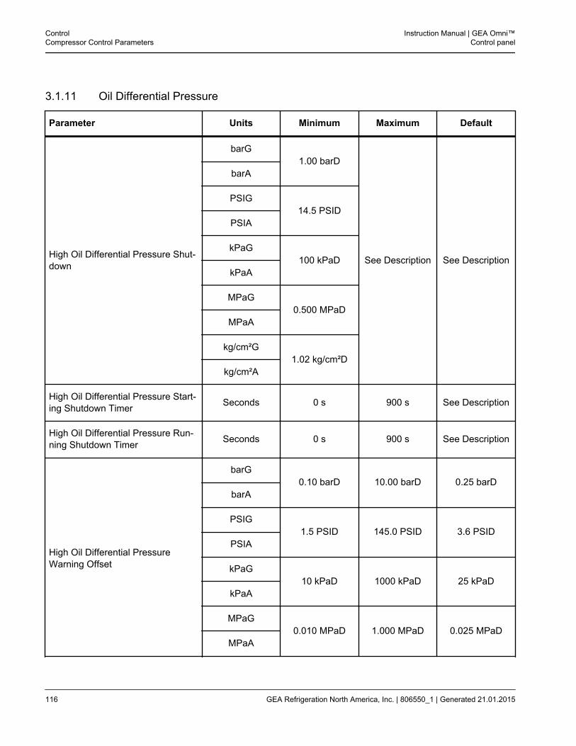
3.1.11 Oil Differential Pressure
Parameter Units Minimum Maximum Default
High Oil Differential Pressure Shut-down
barG1.00 barD
See Description See Description
barA
PSIG14.5 PSID
PSIA
kPaG100 kPaD
kPaA
MPaG0.500 MPaD
MPaA
kg/cm²G1.02 kg/cm²D
kg/cm²A
High Oil Differential Pressure Start-ing Shutdown Timer Seconds 0 s 900 s See Description
High Oil Differential Pressure Run-ning Shutdown Timer Seconds 0 s 900 s See Description
High Oil Differential PressureWarning Offset
barG0.10 barD 10.00 barD 0.25 barD
barA
PSIG1.5 PSID 145.0 PSID 3.6 PSID
PSIA
kPaG10 kPaD 1000 kPaD 25 kPaD
kPaA
MPaG0.010 MPaD 1.000 MPaD 0.025 MPaD
MPaA
ControlCompressor Control Parameters
Instruction Manual | GEA Omni™Control panel
116 GEA Refrigeration North America, Inc. | 806550_1 | Generated 21.01.2015
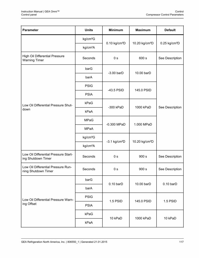
Parameter Units Minimum Maximum Default
kg/cm²G0.10 kg/cm²D 10.20 kg/cm²D 0.25 kg/cm²D
kg/cm²A
High Oil Differential PressureWarning Timer Seconds 0 s 600 s See Description
Low Oil Differential Pressure Shut-down
barG-3.00 barD 10.00 barD
See Description
barA
PSIG-43.5 PSID 145.0 PSID
PSIA
kPaG-300 kPaD 1000 kPaD
kPaA
MPaG-0.300 MPaD 1.000 MPaD
MPaA
kg/cm²G-3.1 kg/cm²D 10.20 kg/cm²D
kg/cm²A
Low Oil Differential Pressure Start-ing Shutdown Timer Seconds 0 s 900 s See Description
Low Oil Differential Pressure Run-ning Shutdown Timer Seconds 0 s 900 s See Description
Low Oil Differential Pressure Warn-ing Offset
barG0.10 barD 10.00 barD 0.10 barD
barA
PSIG1.5 PSID 145.0 PSID 1.5 PSID
PSIA
kPaG10 kPaD 1000 kPaD 10 kPaD
kPaA
Instruction Manual | GEA Omni™Control panel
ControlCompressor Control Parameters
GEA Refrigeration North America, Inc. | 806550_1 | Generated 21.01.2015 117
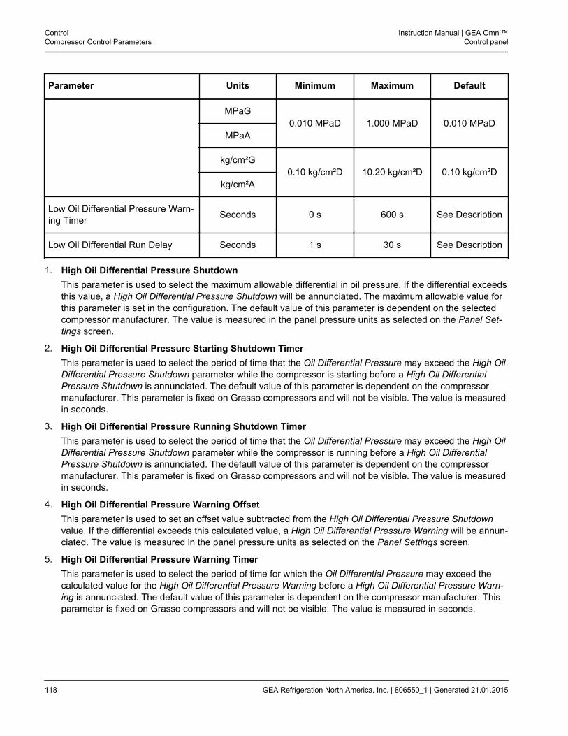
Parameter Units Minimum Maximum Default
MPaG0.010 MPaD 1.000 MPaD 0.010 MPaD
MPaA
kg/cm²G0.10 kg/cm²D 10.20 kg/cm²D 0.10 kg/cm²D
kg/cm²A
Low Oil Differential Pressure Warn-ing Timer Seconds 0 s 600 s See Description
Low Oil Differential Run Delay Seconds 1 s 30 s See Description
1. High Oil Differential Pressure ShutdownThis parameter is used to select the maximum allowable differential in oil pressure. If the differential exceedsthis value, a High Oil Differential Pressure Shutdown will be annunciated. The maximum allowable value forthis parameter is set in the configuration. The default value of this parameter is dependent on the selectedcompressor manufacturer. The value is measured in the panel pressure units as selected on the Panel Set-tings screen.
2. High Oil Differential Pressure Starting Shutdown TimerThis parameter is used to select the period of time that the Oil Differential Pressure may exceed the High OilDifferential Pressure Shutdown parameter while the compressor is starting before a High Oil DifferentialPressure Shutdown is annunciated. The default value of this parameter is dependent on the compressormanufacturer. This parameter is fixed on Grasso compressors and will not be visible. The value is measuredin seconds.
3. High Oil Differential Pressure Running Shutdown TimerThis parameter is used to select the period of time that the Oil Differential Pressure may exceed the High OilDifferential Pressure Shutdown parameter while the compressor is running before a High Oil DifferentialPressure Shutdown is annunciated. The default value of this parameter is dependent on the compressormanufacturer. This parameter is fixed on Grasso compressors and will not be visible. The value is measuredin seconds.
4. High Oil Differential Pressure Warning OffsetThis parameter is used to set an offset value subtracted from the High Oil Differential Pressure Shutdownvalue. If the differential exceeds this calculated value, a High Oil Differential Pressure Warning will be annun-ciated. The value is measured in the panel pressure units as selected on the Panel Settings screen.
5. High Oil Differential Pressure Warning TimerThis parameter is used to select the period of time for which the Oil Differential Pressure may exceed thecalculated value for the High Oil Differential Pressure Warning before a High Oil Differential Pressure Warn-ing is annunciated. The default value of this parameter is dependent on the compressor manufacturer. Thisparameter is fixed on Grasso compressors and will not be visible. The value is measured in seconds.
ControlCompressor Control Parameters
Instruction Manual | GEA Omni™Control panel
118 GEA Refrigeration North America, Inc. | 806550_1 | Generated 21.01.2015
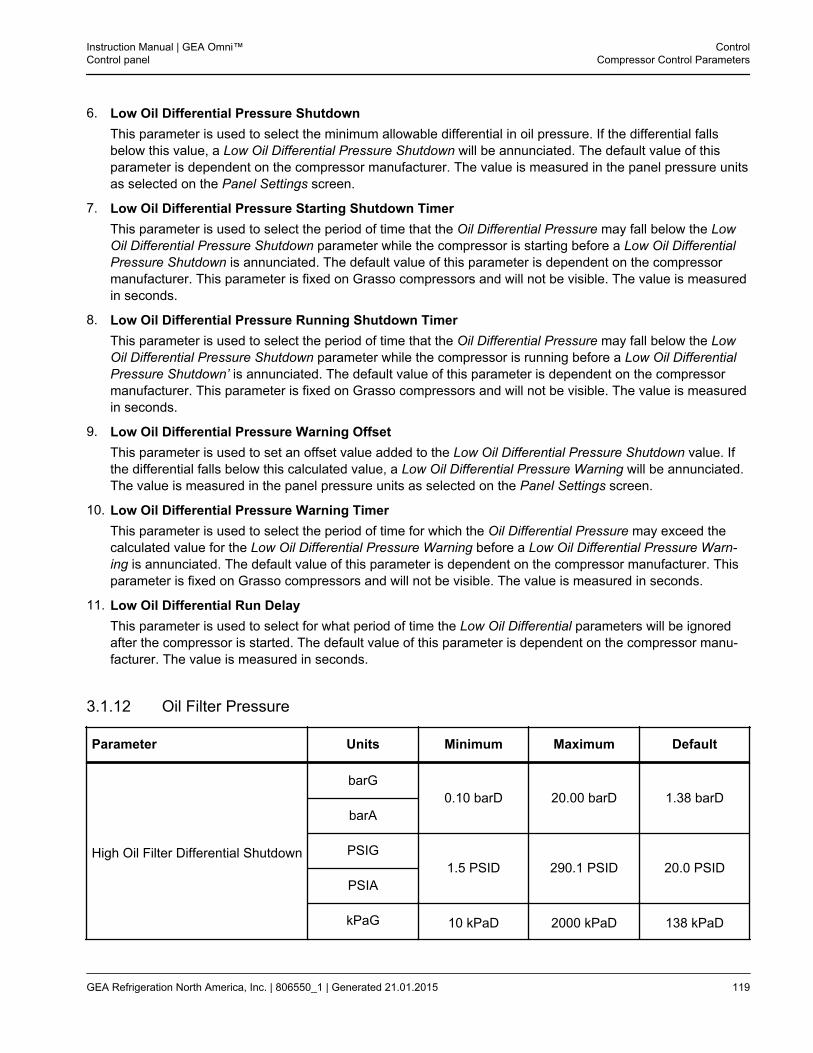
6. Low Oil Differential Pressure ShutdownThis parameter is used to select the minimum allowable differential in oil pressure. If the differential fallsbelow this value, a Low Oil Differential Pressure Shutdown will be annunciated. The default value of thisparameter is dependent on the compressor manufacturer. The value is measured in the panel pressure unitsas selected on the Panel Settings screen.
7. Low Oil Differential Pressure Starting Shutdown TimerThis parameter is used to select the period of time that the Oil Differential Pressure may fall below the LowOil Differential Pressure Shutdown parameter while the compressor is starting before a Low Oil DifferentialPressure Shutdown is annunciated. The default value of this parameter is dependent on the compressormanufacturer. This parameter is fixed on Grasso compressors and will not be visible. The value is measuredin seconds.
8. Low Oil Differential Pressure Running Shutdown TimerThis parameter is used to select the period of time that the Oil Differential Pressure may fall below the LowOil Differential Pressure Shutdown parameter while the compressor is running before a Low Oil DifferentialPressure Shutdown’ is annunciated. The default value of this parameter is dependent on the compressormanufacturer. This parameter is fixed on Grasso compressors and will not be visible. The value is measuredin seconds.
9. Low Oil Differential Pressure Warning OffsetThis parameter is used to set an offset value added to the Low Oil Differential Pressure Shutdown value. Ifthe differential falls below this calculated value, a Low Oil Differential Pressure Warning will be annunciated.The value is measured in the panel pressure units as selected on the Panel Settings screen.
10. Low Oil Differential Pressure Warning TimerThis parameter is used to select the period of time for which the Oil Differential Pressure may exceed thecalculated value for the Low Oil Differential Pressure Warning before a Low Oil Differential Pressure Warn-ing is annunciated. The default value of this parameter is dependent on the compressor manufacturer. Thisparameter is fixed on Grasso compressors and will not be visible. The value is measured in seconds.
11. Low Oil Differential Run DelayThis parameter is used to select for what period of time the Low Oil Differential parameters will be ignoredafter the compressor is started. The default value of this parameter is dependent on the compressor manu-facturer. The value is measured in seconds.
3.1.12 Oil Filter Pressure
Parameter Units Minimum Maximum Default
High Oil Filter Differential Shutdown
barG0.10 barD 20.00 barD 1.38 barD
barA
PSIG1.5 PSID 290.1 PSID 20.0 PSID
PSIA
kPaG 10 kPaD 2000 kPaD 138 kPaD
Instruction Manual | GEA Omni™Control panel
ControlCompressor Control Parameters
GEA Refrigeration North America, Inc. | 806550_1 | Generated 21.01.2015 119
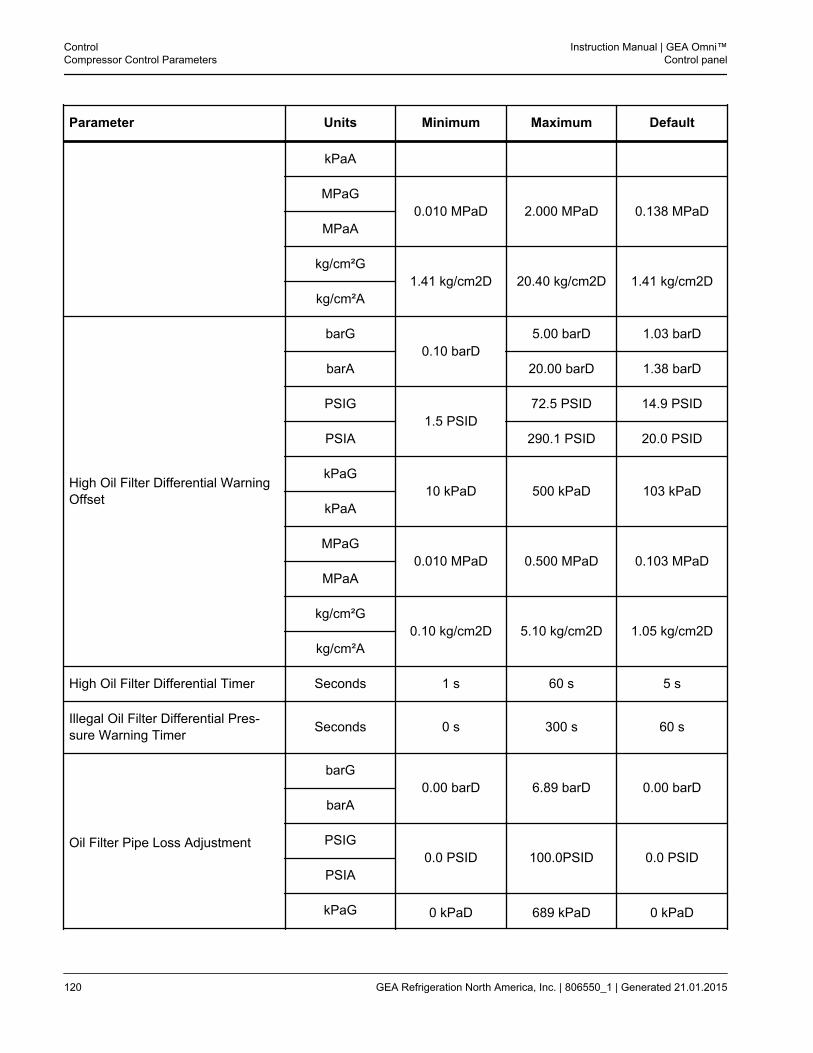
Parameter Units Minimum Maximum Default
kPaA
MPaG0.010 MPaD 2.000 MPaD 0.138 MPaD
MPaA
kg/cm²G1.41 kg/cm2D 20.40 kg/cm2D 1.41 kg/cm2D
kg/cm²A
High Oil Filter Differential WarningOffset
barG0.10 barD
5.00 barD 1.03 barD
barA 20.00 barD 1.38 barD
PSIG1.5 PSID
72.5 PSID 14.9 PSID
PSIA 290.1 PSID 20.0 PSID
kPaG10 kPaD 500 kPaD 103 kPaD
kPaA
MPaG0.010 MPaD 0.500 MPaD 0.103 MPaD
MPaA
kg/cm²G0.10 kg/cm2D 5.10 kg/cm2D 1.05 kg/cm2D
kg/cm²A
High Oil Filter Differential Timer Seconds 1 s 60 s 5 s
Illegal Oil Filter Differential Pres-sure Warning Timer Seconds 0 s 300 s 60 s
Oil Filter Pipe Loss Adjustment
barG0.00 barD 6.89 barD 0.00 barD
barA
PSIG0.0 PSID 100.0PSID 0.0 PSID
PSIA
kPaG 0 kPaD 689 kPaD 0 kPaD
ControlCompressor Control Parameters
Instruction Manual | GEA Omni™Control panel
120 GEA Refrigeration North America, Inc. | 806550_1 | Generated 21.01.2015
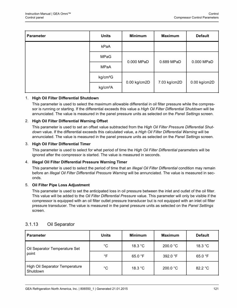
Parameter Units Minimum Maximum Default
kPaA
MPaG0.000 MPaD 0.689 MPaD 0.000 MPaD
MPaA
kg/cm²G0.00 kg/cm2D 7.03 kg/cm2D 0.00 kg/cm2D
kg/cm²A
1. High Oil Filter Differential ShutdownThis parameter is used to select the maximum allowable differential in oil filter pressure while the compres-sor is running or starting. If the differential exceeds this value a High Oil Filter Differential Shutdown will beannunciated. The value is measured in the panel pressure units as selected on the Panel Settings screen.
2. High Oil Filter Differential Warning OffsetThis parameter is used to set an offset value subtracted from the High Oil Filter Pressure Differential Shut-down value. If the differential exceeds this calculated value, a High Oil Filter Differential Warning will beannunciated. The value is measured in the panel pressure units as selected on the Panel Settings screen.
3. High Oil Filter Differential TimerThis parameter is used to select for what period of time the High Oil Filter Differential parameters will beignored after the compressor is started. The value is measured in seconds.
4. Illegal Oil Filter Differential Pressure Warning TimerThis parameter is used to select the period of time that an Illegal Oil Filter Differential condition may remainbefore an Illegal Oil Filter Differential Pressure Warning will be annunciated. The value is measured in sec-onds.
5. Oil Filter Pipe Loss AdjustmentThis parameter is used to set the anticipated loss in oil pressure between the inlet and outlet of the oil filter.This value will be added to the Oil Filter Differential Pressure value. This parameter will only be visible if thecompressor is equipped with an oil filter outlet pressure transducer but is not equipped with an inlet oil filterpressure transducer. The value is measured in the panel pressure units as selected on the Panel Settingsscreen.
3.1.13 Oil Separator
Parameter Units Minimum Maximum Default
Oil Separator Temperature Setpoint
°C 18.3 °C 200.0 °C 18.3 °C
°F 65.0 °F 392.0 °F 65.0 °F
High Oil Separator TemperatureShutdown
°C 18.3 °C 200.0 °C 82.2 °C
Instruction Manual | GEA Omni™Control panel
ControlCompressor Control Parameters
GEA Refrigeration North America, Inc. | 806550_1 | Generated 21.01.2015 121
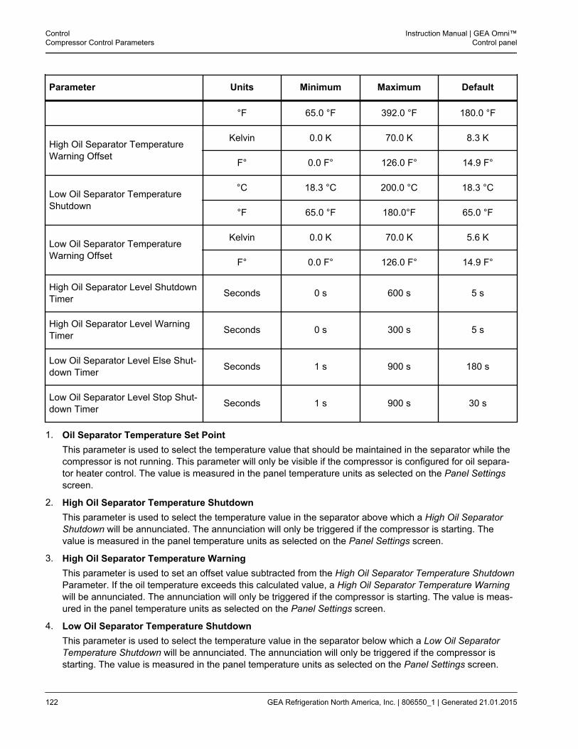
Parameter Units Minimum Maximum Default
°F 65.0 °F 392.0 °F 180.0 °F
High Oil Separator TemperatureWarning Offset
Kelvin 0.0 K 70.0 K 8.3 K
F° 0.0 F° 126.0 F° 14.9 F°
Low Oil Separator TemperatureShutdown
°C 18.3 °C 200.0 °C 18.3 °C
°F 65.0 °F 180.0°F 65.0 °F
Low Oil Separator TemperatureWarning Offset
Kelvin 0.0 K 70.0 K 5.6 K
F° 0.0 F° 126.0 F° 14.9 F°
High Oil Separator Level ShutdownTimer Seconds 0 s 600 s 5 s
High Oil Separator Level WarningTimer Seconds 0 s 300 s 5 s
Low Oil Separator Level Else Shut-down Timer Seconds 1 s 900 s 180 s
Low Oil Separator Level Stop Shut-down Timer Seconds 1 s 900 s 30 s
1. Oil Separator Temperature Set PointThis parameter is used to select the temperature value that should be maintained in the separator while thecompressor is not running. This parameter will only be visible if the compressor is configured for oil separa-tor heater control. The value is measured in the panel temperature units as selected on the Panel Settingsscreen.
2. High Oil Separator Temperature ShutdownThis parameter is used to select the temperature value in the separator above which a High Oil SeparatorShutdown will be annunciated. The annunciation will only be triggered if the compressor is starting. Thevalue is measured in the panel temperature units as selected on the Panel Settings screen.
3. High Oil Separator Temperature WarningThis parameter is used to set an offset value subtracted from the High Oil Separator Temperature ShutdownParameter. If the oil temperature exceeds this calculated value, a High Oil Separator Temperature Warningwill be annunciated. The annunciation will only be triggered if the compressor is starting. The value is meas-ured in the panel temperature units as selected on the Panel Settings screen.
4. Low Oil Separator Temperature ShutdownThis parameter is used to select the temperature value in the separator below which a Low Oil SeparatorTemperature Shutdown will be annunciated. The annunciation will only be triggered if the compressor isstarting. The value is measured in the panel temperature units as selected on the Panel Settings screen.
ControlCompressor Control Parameters
Instruction Manual | GEA Omni™Control panel
122 GEA Refrigeration North America, Inc. | 806550_1 | Generated 21.01.2015
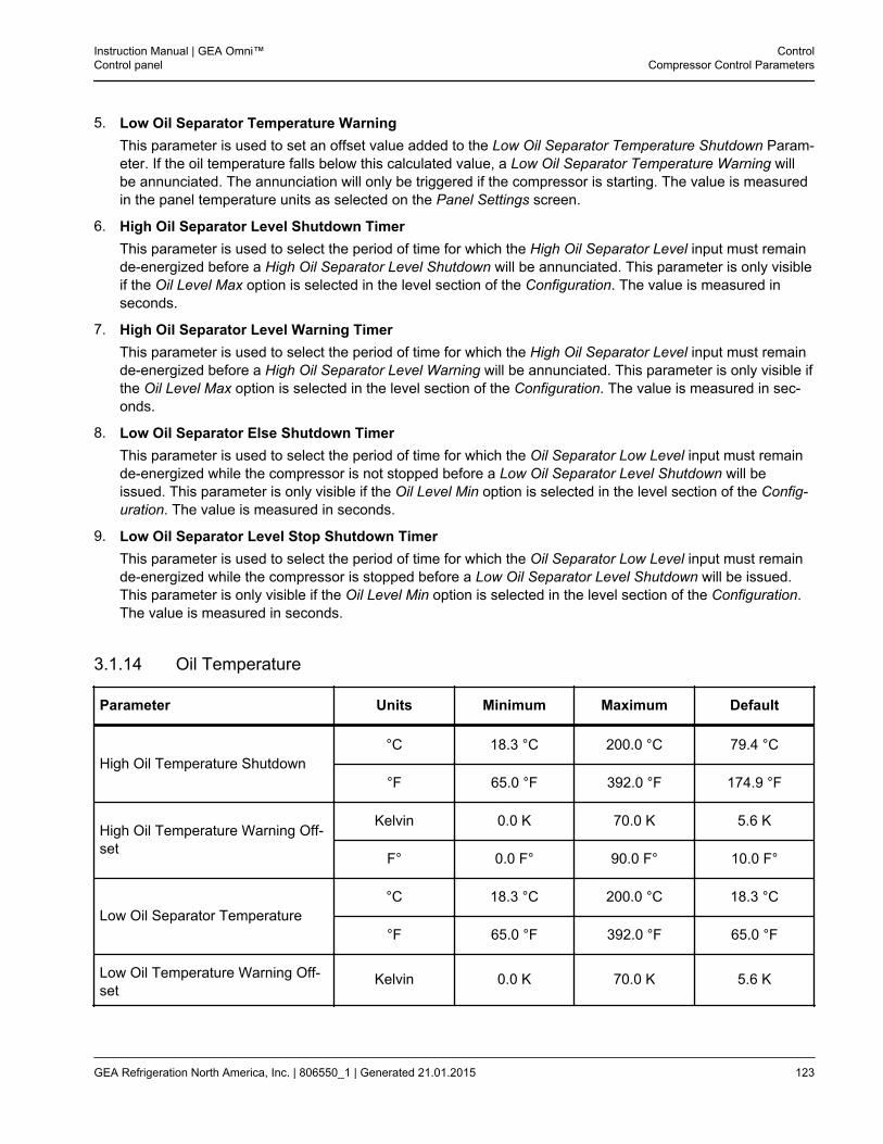
5. Low Oil Separator Temperature WarningThis parameter is used to set an offset value added to the Low Oil Separator Temperature Shutdown Param-eter. If the oil temperature falls below this calculated value, a Low Oil Separator Temperature Warning willbe annunciated. The annunciation will only be triggered if the compressor is starting. The value is measuredin the panel temperature units as selected on the Panel Settings screen.
6. High Oil Separator Level Shutdown TimerThis parameter is used to select the period of time for which the High Oil Separator Level input must remainde-energized before a High Oil Separator Level Shutdown will be annunciated. This parameter is only visibleif the Oil Level Max option is selected in the level section of the Configuration. The value is measured inseconds.
7. High Oil Separator Level Warning TimerThis parameter is used to select the period of time for which the High Oil Separator Level input must remainde-energized before a High Oil Separator Level Warning will be annunciated. This parameter is only visible ifthe Oil Level Max option is selected in the level section of the Configuration. The value is measured in sec-onds.
8. Low Oil Separator Else Shutdown TimerThis parameter is used to select the period of time for which the Oil Separator Low Level input must remainde-energized while the compressor is not stopped before a Low Oil Separator Level Shutdown will beissued. This parameter is only visible if the Oil Level Min option is selected in the level section of the Config-uration. The value is measured in seconds.
9. Low Oil Separator Level Stop Shutdown TimerThis parameter is used to select the period of time for which the Oil Separator Low Level input must remainde-energized while the compressor is stopped before a Low Oil Separator Level Shutdown will be issued.This parameter is only visible if the Oil Level Min option is selected in the level section of the Configuration.The value is measured in seconds.
3.1.14 Oil Temperature
Parameter Units Minimum Maximum Default
High Oil Temperature Shutdown°C 18.3 °C 200.0 °C 79.4 °C
°F 65.0 °F 392.0 °F 174.9 °F
High Oil Temperature Warning Off-set
Kelvin 0.0 K 70.0 K 5.6 K
F° 0.0 F° 90.0 F° 10.0 F°
Low Oil Separator Temperature°C 18.3 °C 200.0 °C 18.3 °C
°F 65.0 °F 392.0 °F 65.0 °F
Low Oil Temperature Warning Off-set
Kelvin 0.0 K 70.0 K 5.6 K
Instruction Manual | GEA Omni™Control panel
ControlCompressor Control Parameters
GEA Refrigeration North America, Inc. | 806550_1 | Generated 21.01.2015 123
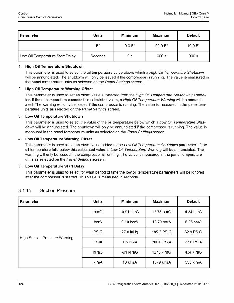
Parameter Units Minimum Maximum Default
F° 0.0 F° 90.0 F° 10.0 F°
Low Oil Temperature Start Delay Seconds 0 s 600 s 300 s
1. High Oil Temperature ShutdownThis parameter is used to select the oil temperature value above which a High Oil Temperature Shutdownwill be annunciated. The shutdown will only be issued if the compressor is running. The value is measured inthe panel temperature units as selected on the Panel Settings screen.
2. High Oil Temperature Warning OffsetThis parameter is used to set an offset value subtracted from the High Oil Temperature Shutdown parame-ter. If the oil temperature exceeds this calculated value, a High Oil Temperature Warning will be annunci-ated. The warning will only be issued if the compressor is running. The value is measured in the panel tem-perature units as selected on the Panel Settings screen.
3. Low Oil Temperature ShutdownThis parameter is used to select the value of the oil temperature below which a Low Oil Temperature Shut-down will be annunciated. The shutdown will only be annunciated if the compressor is running. The value ismeasured in the panel temperature units as selected on the Panel Settings screen.
4. Low Oil Temperature Warning OffsetThis parameter is used to set an offset value added to the Low Oil Temperature Shutdown parameter. If theoil temperature falls below this calculated value, a Low Oil Temperature Warning will be annunciated. Thewarning will only be issued if the compressor is running. The value is measured in the panel temperatureunits as selected on the Panel Settings screen.
5. Low Oil Temperature Start DelayThis parameter is used to select for what period of time the low oil temperature parameters will be ignoredafter the compressor is started. This value is measured in seconds.
3.1.15 Suction Pressure
Parameter Units Minimum Maximum Default
High Suction Pressure Warning
barG -0.91 barG 12.78 barG 4.34 barG
barA 0.10 barA 13.79 barA 5.35 barA
PSIG 27.0 inHg 185.3 PSIG 62.9 PSIG
PSIA 1.5 PSIA 200.0 PSIA 77.6 PSIA
kPaG -91 kPaG 1278 kPaG 434 kPaG
kPaA 10 kPaA 1379 kPaA 535 kPaA
ControlCompressor Control Parameters
Instruction Manual | GEA Omni™Control panel
124 GEA Refrigeration North America, Inc. | 806550_1 | Generated 21.01.2015
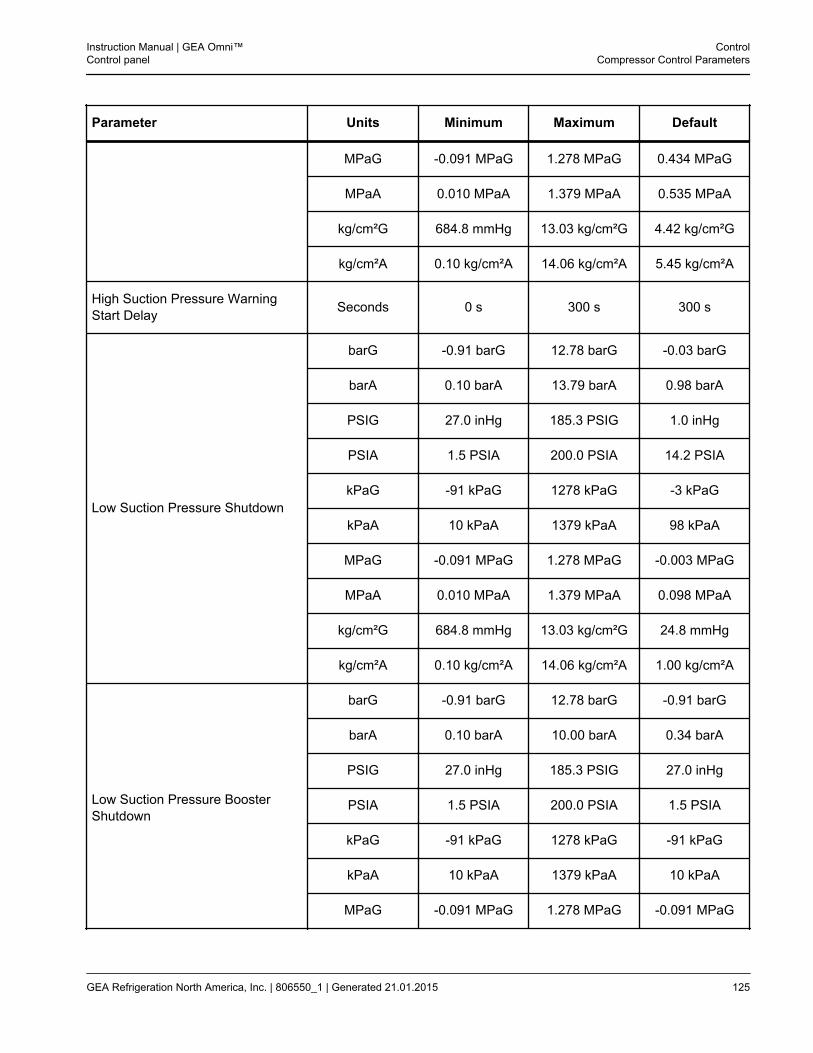
Parameter Units Minimum Maximum Default
MPaG -0.091 MPaG 1.278 MPaG 0.434 MPaG
MPaA 0.010 MPaA 1.379 MPaA 0.535 MPaA
kg/cm²G 684.8 mmHg 13.03 kg/cm²G 4.42 kg/cm²G
kg/cm²A 0.10 kg/cm²A 14.06 kg/cm²A 5.45 kg/cm²A
High Suction Pressure WarningStart Delay Seconds 0 s 300 s 300 s
Low Suction Pressure Shutdown
barG -0.91 barG 12.78 barG -0.03 barG
barA 0.10 barA 13.79 barA 0.98 barA
PSIG 27.0 inHg 185.3 PSIG 1.0 inHg
PSIA 1.5 PSIA 200.0 PSIA 14.2 PSIA
kPaG -91 kPaG 1278 kPaG -3 kPaG
kPaA 10 kPaA 1379 kPaA 98 kPaA
MPaG -0.091 MPaG 1.278 MPaG -0.003 MPaG
MPaA 0.010 MPaA 1.379 MPaA 0.098 MPaA
kg/cm²G 684.8 mmHg 13.03 kg/cm²G 24.8 mmHg
kg/cm²A 0.10 kg/cm²A 14.06 kg/cm²A 1.00 kg/cm²A
Low Suction Pressure BoosterShutdown
barG -0.91 barG 12.78 barG -0.91 barG
barA 0.10 barA 10.00 barA 0.34 barA
PSIG 27.0 inHg 185.3 PSIG 27.0 inHg
PSIA 1.5 PSIA 200.0 PSIA 1.5 PSIA
kPaG -91 kPaG 1278 kPaG -91 kPaG
kPaA 10 kPaA 1379 kPaA 10 kPaA
MPaG -0.091 MPaG 1.278 MPaG -0.091 MPaG
Instruction Manual | GEA Omni™Control panel
ControlCompressor Control Parameters
GEA Refrigeration North America, Inc. | 806550_1 | Generated 21.01.2015 125
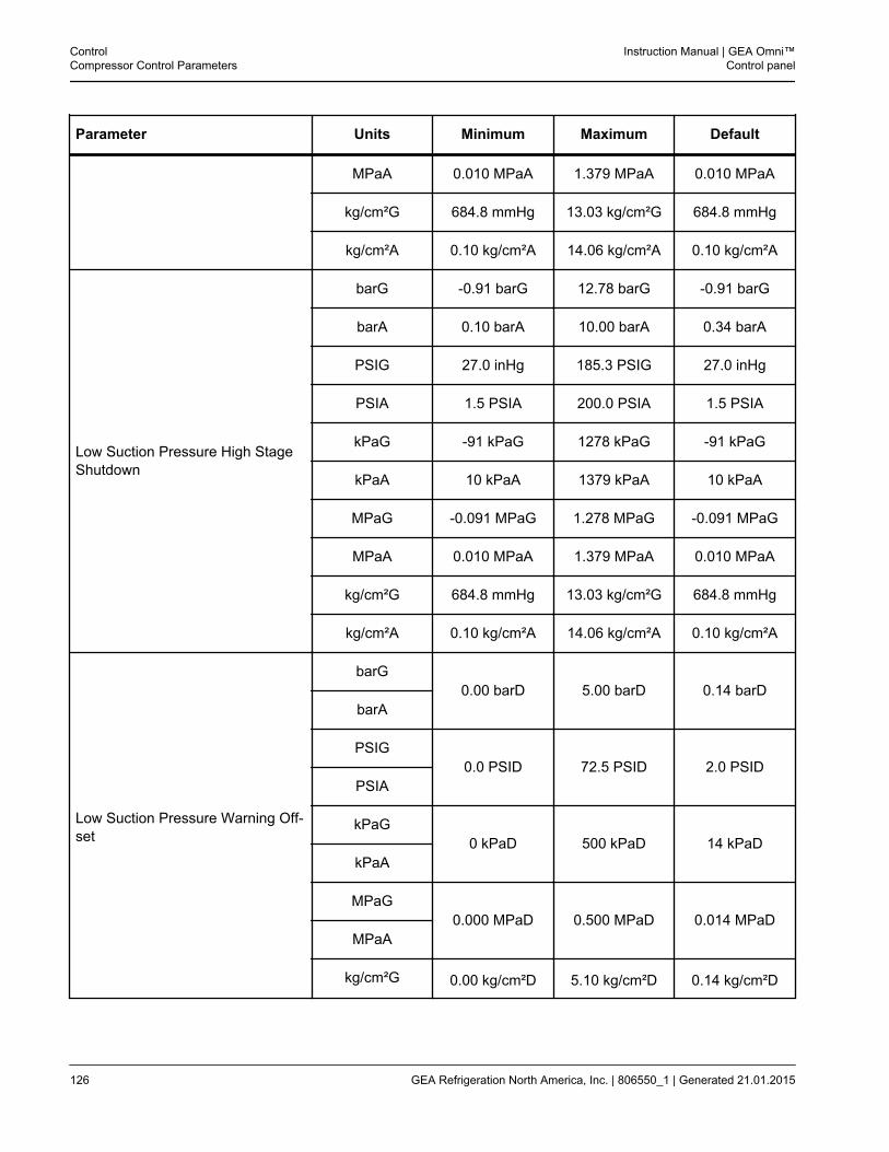
Parameter Units Minimum Maximum Default
MPaA 0.010 MPaA 1.379 MPaA 0.010 MPaA
kg/cm²G 684.8 mmHg 13.03 kg/cm²G 684.8 mmHg
kg/cm²A 0.10 kg/cm²A 14.06 kg/cm²A 0.10 kg/cm²A
Low Suction Pressure High StageShutdown
barG -0.91 barG 12.78 barG -0.91 barG
barA 0.10 barA 10.00 barA 0.34 barA
PSIG 27.0 inHg 185.3 PSIG 27.0 inHg
PSIA 1.5 PSIA 200.0 PSIA 1.5 PSIA
kPaG -91 kPaG 1278 kPaG -91 kPaG
kPaA 10 kPaA 1379 kPaA 10 kPaA
MPaG -0.091 MPaG 1.278 MPaG -0.091 MPaG
MPaA 0.010 MPaA 1.379 MPaA 0.010 MPaA
kg/cm²G 684.8 mmHg 13.03 kg/cm²G 684.8 mmHg
kg/cm²A 0.10 kg/cm²A 14.06 kg/cm²A 0.10 kg/cm²A
Low Suction Pressure Warning Off-set
barG0.00 barD 5.00 barD 0.14 barD
barA
PSIG0.0 PSID 72.5 PSID 2.0 PSID
PSIA
kPaG0 kPaD 500 kPaD 14 kPaD
kPaA
MPaG0.000 MPaD 0.500 MPaD 0.014 MPaD
MPaA
kg/cm²G 0.00 kg/cm²D 5.10 kg/cm²D 0.14 kg/cm²D
ControlCompressor Control Parameters
Instruction Manual | GEA Omni™Control panel
126 GEA Refrigeration North America, Inc. | 806550_1 | Generated 21.01.2015
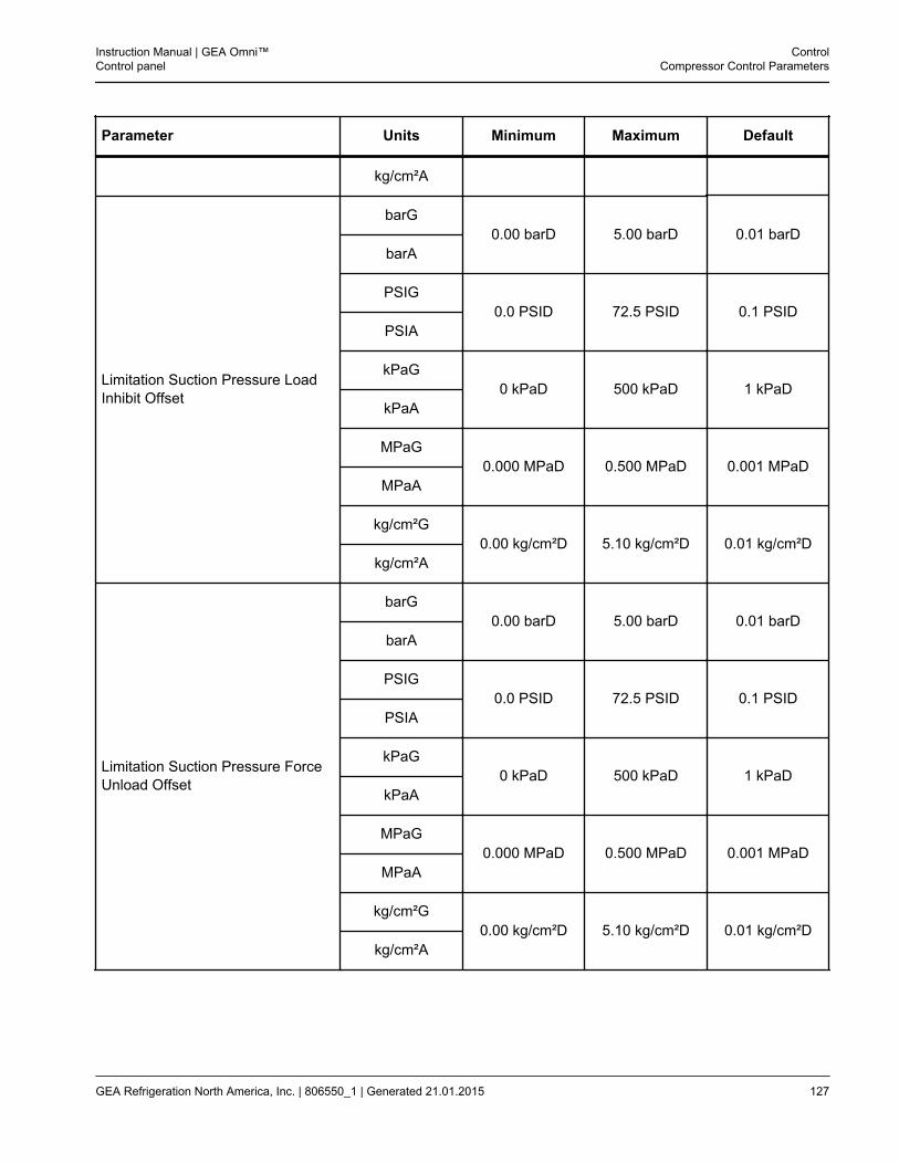
Parameter Units Minimum Maximum Default
kg/cm²A
Limitation Suction Pressure LoadInhibit Offset
barG0.00 barD 5.00 barD 0.01 barD
barA
PSIG0.0 PSID 72.5 PSID 0.1 PSID
PSIA
kPaG0 kPaD 500 kPaD 1 kPaD
kPaA
MPaG0.000 MPaD 0.500 MPaD 0.001 MPaD
MPaA
kg/cm²G0.00 kg/cm²D 5.10 kg/cm²D 0.01 kg/cm²D
kg/cm²A
Limitation Suction Pressure ForceUnload Offset
barG0.00 barD 5.00 barD 0.01 barD
barA
PSIG0.0 PSID 72.5 PSID 0.1 PSID
PSIA
kPaG0 kPaD 500 kPaD 1 kPaD
kPaA
MPaG0.000 MPaD 0.500 MPaD 0.001 MPaD
MPaA
kg/cm²G0.00 kg/cm²D 5.10 kg/cm²D 0.01 kg/cm²D
kg/cm²A
Instruction Manual | GEA Omni™Control panel
ControlCompressor Control Parameters
GEA Refrigeration North America, Inc. | 806550_1 | Generated 21.01.2015 127
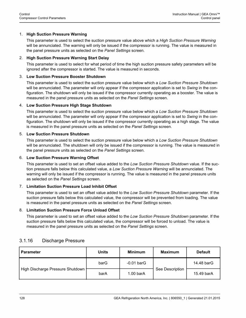
1. High Suction Pressure WarningThis parameter is used to select the suction pressure value above which a High Suction Pressure Warningwill be annunciated. The warning will only be issued if the compressor is running. The value is measured inthe panel pressure units as selected on the Panel Settings screen.
2. High Suction Pressure Warning Start DelayThis parameter is used to select for what period of time the high suction pressure safety parameters will beignored after the compressor is started. The value is measured in seconds.
3. Low Suction Pressure Booster ShutdownThis parameter is used to select the suction pressure value below which a Low Suction Pressure Shutdownwill be annunciated. The parameter will only appear if the compressor application is set to Swing in the con-figuration. The shutdown will only be issued if the compressor currently operating as a booster. The value ismeasured in the panel pressure units as selected on the Panel Settings screen.
4. Low Suction Pressure High Stage ShutdownThis parameter is used to select the suction pressure value below which a Low Suction Pressure Shutdownwill be annunciated. The parameter will only appear if the compressor application is set to Swing in the con-figuration. The shutdown will only be issued if the compressor currently operating as a high stage. The valueis measured in the panel pressure units as selected on the Panel Settings screen.
5. Low Suction Pressure ShutdownThis parameter is used to select the suction pressure value below which a Low Suction Pressure Shutdownwill be annunciated. The shutdown will only be issued if the compressor is running. The value is measured inthe panel pressure units as selected on the Panel Settings screen.
6. Low Suction Pressure Warning OffsetThis parameter is used to set an offset value added to the Low Suction Pressure Shutdown value. If the suc-tion pressure falls below this calculated value, a Low Suction Pressure Warning will be annunciated. Thewarning will only be issued if the compressor is running. The value is measured in the panel pressure unitsas selected on the Panel Settings screen.
7. Limitation Suction Pressure Load Inhibit OffsetThis parameter is used to set an offset value added to the Low Suction Pressure Shutdown parameter. If thesuction pressure falls below this calculated value, the compressor will be prevented from loading. The valueis measured in the panel pressure units as selected on the Panel Settings screen.
8. Limitation Suction Pressure Force Unload OffsetThis parameter is used to set an offset value added to the Low Suction Pressure Shutdown parameter. If thesuction pressure falls below this calculated value, the compressor will be forced to unload. The value ismeasured in the panel pressure units as selected on the Panel Settings screen.
3.1.16 Discharge Pressure
Parameter Units Minimum Maximum Default
High Discharge Pressure ShutdownbarG -0.01 barG
See Description14.48 barG
barA 1.00 barA 15.49 barA
ControlCompressor Control Parameters
Instruction Manual | GEA Omni™Control panel
128 GEA Refrigeration North America, Inc. | 806550_1 | Generated 21.01.2015
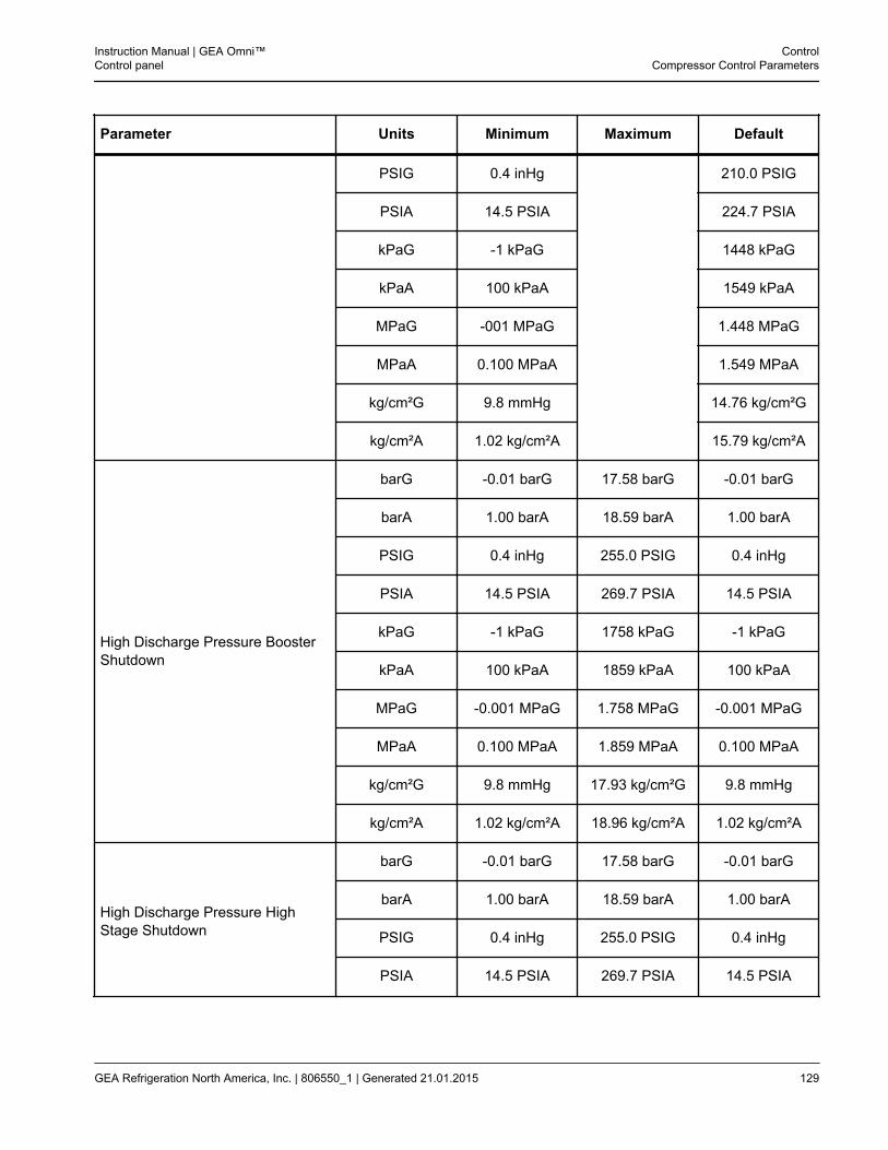
Parameter Units Minimum Maximum Default
PSIG 0.4 inHg 210.0 PSIG
PSIA 14.5 PSIA 224.7 PSIA
kPaG -1 kPaG 1448 kPaG
kPaA 100 kPaA 1549 kPaA
MPaG -001 MPaG 1.448 MPaG
MPaA 0.100 MPaA 1.549 MPaA
kg/cm²G 9.8 mmHg 14.76 kg/cm²G
kg/cm²A 1.02 kg/cm²A 15.79 kg/cm²A
High Discharge Pressure BoosterShutdown
barG -0.01 barG 17.58 barG -0.01 barG
barA 1.00 barA 18.59 barA 1.00 barA
PSIG 0.4 inHg 255.0 PSIG 0.4 inHg
PSIA 14.5 PSIA 269.7 PSIA 14.5 PSIA
kPaG -1 kPaG 1758 kPaG -1 kPaG
kPaA 100 kPaA 1859 kPaA 100 kPaA
MPaG -0.001 MPaG 1.758 MPaG -0.001 MPaG
MPaA 0.100 MPaA 1.859 MPaA 0.100 MPaA
kg/cm²G 9.8 mmHg 17.93 kg/cm²G 9.8 mmHg
kg/cm²A 1.02 kg/cm²A 18.96 kg/cm²A 1.02 kg/cm²A
High Discharge Pressure HighStage Shutdown
barG -0.01 barG 17.58 barG -0.01 barG
barA 1.00 barA 18.59 barA 1.00 barA
PSIG 0.4 inHg 255.0 PSIG 0.4 inHg
PSIA 14.5 PSIA 269.7 PSIA 14.5 PSIA
Instruction Manual | GEA Omni™Control panel
ControlCompressor Control Parameters
GEA Refrigeration North America, Inc. | 806550_1 | Generated 21.01.2015 129
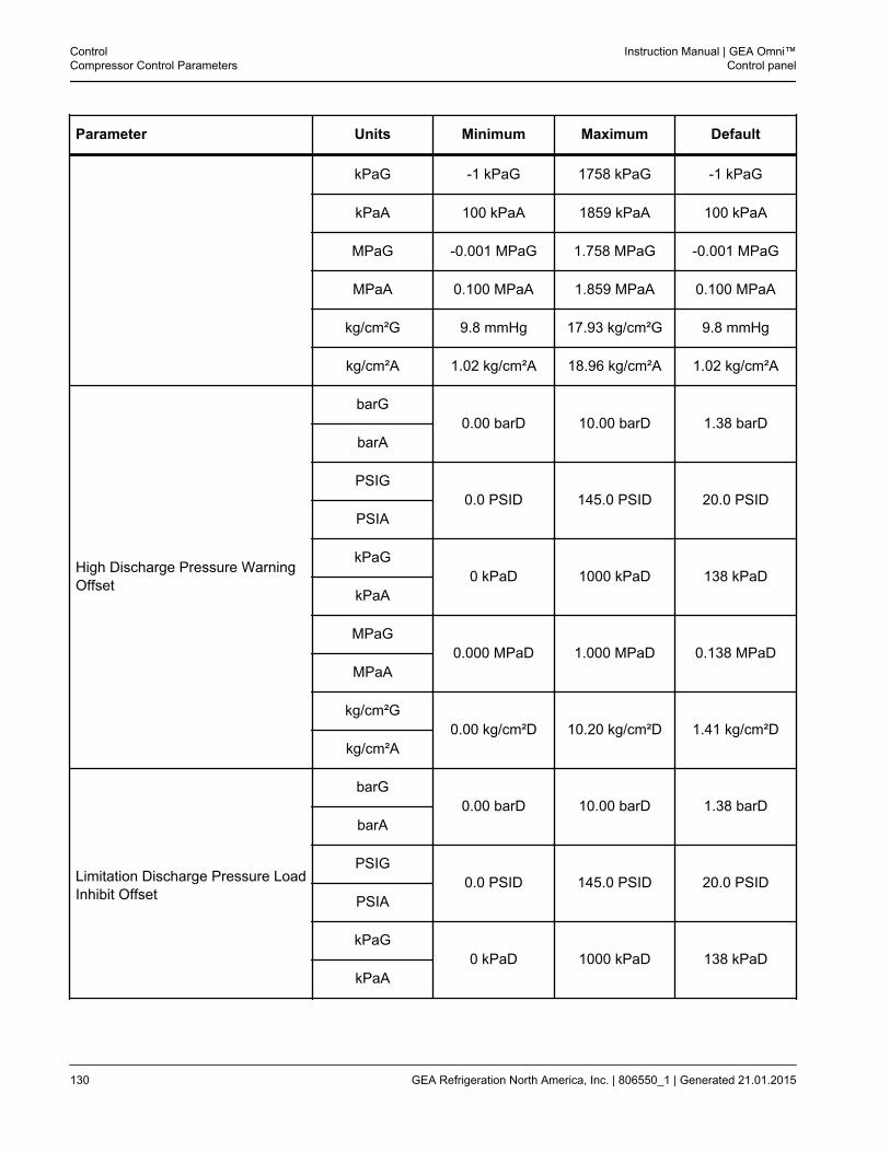
Parameter Units Minimum Maximum Default
kPaG -1 kPaG 1758 kPaG -1 kPaG
kPaA 100 kPaA 1859 kPaA 100 kPaA
MPaG -0.001 MPaG 1.758 MPaG -0.001 MPaG
MPaA 0.100 MPaA 1.859 MPaA 0.100 MPaA
kg/cm²G 9.8 mmHg 17.93 kg/cm²G 9.8 mmHg
kg/cm²A 1.02 kg/cm²A 18.96 kg/cm²A 1.02 kg/cm²A
High Discharge Pressure WarningOffset
barG0.00 barD 10.00 barD 1.38 barD
barA
PSIG0.0 PSID 145.0 PSID 20.0 PSID
PSIA
kPaG0 kPaD 1000 kPaD 138 kPaD
kPaA
MPaG0.000 MPaD 1.000 MPaD 0.138 MPaD
MPaA
kg/cm²G0.00 kg/cm²D 10.20 kg/cm²D 1.41 kg/cm²D
kg/cm²A
Limitation Discharge Pressure LoadInhibit Offset
barG0.00 barD 10.00 barD 1.38 barD
barA
PSIG0.0 PSID 145.0 PSID 20.0 PSID
PSIA
kPaG0 kPaD 1000 kPaD 138 kPaD
kPaA
ControlCompressor Control Parameters
Instruction Manual | GEA Omni™Control panel
130 GEA Refrigeration North America, Inc. | 806550_1 | Generated 21.01.2015
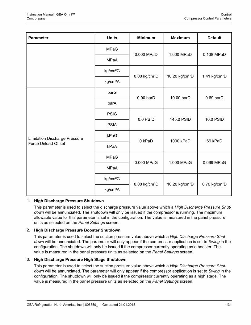
Parameter Units Minimum Maximum Default
MPaG0.000 MPaD 1.000 MPaD 0.138 MPaD
MPaA
kg/cm²G0.00 kg/cm²D 10.20 kg/cm²D 1.41 kg/cm²D
kg/cm²A
Limitation Discharge PressureForce Unload Offset
barG0.00 barD 10.00 barD 0.69 barD
barA
PSIG0.0 PSID 145.0 PSID 10.0 PSID
PSIA
kPaG0 kPaD 1000 kPaD 69 kPaD
kPaA
MPaG0.000 MPaG 1.000 MPaG 0.069 MPaG
MPaA
kg/cm²G0.00 kg/cm²D 10.20 kg/cm²D 0.70 kg/cm²D
kg/cm²A
1. High Discharge Pressure ShutdownThis parameter is used to select the discharge pressure value above which a High Discharge Pressure Shut-down will be annunciated. The shutdown will only be issued if the compressor is running. The maximumallowable value for this parameter is set in the configuration. The value is measured in the panel pressureunits as selected on the Panel Settings screen.
2. High Discharge Pressure Booster ShutdownThis parameter is used to select the suction pressure value above which a High Discharge Pressure Shut-down will be annunciated. The parameter will only appear if the compressor application is set to Swing in theconfiguration. The shutdown will only be issued if the compressor currently operating as a booster. Thevalue is measured in the panel pressure units as selected on the Panel Settings screen.
3. High Discharge Pressure High Stage ShutdownThis parameter is used to select the suction pressure value above which a High Discharge Pressure Shut-down will be annunciated. The parameter will only appear if the compressor application is set to Swing in theconfiguration. The shutdown will only be issued if the compressor currently operating as a high stage. Thevalue is measured in the panel pressure units as selected on the Panel Settings screen.
Instruction Manual | GEA Omni™Control panel
ControlCompressor Control Parameters
GEA Refrigeration North America, Inc. | 806550_1 | Generated 21.01.2015 131
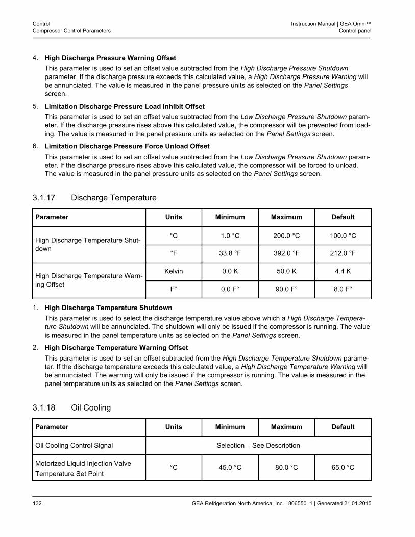
4. High Discharge Pressure Warning OffsetThis parameter is used to set an offset value subtracted from the High Discharge Pressure Shutdownparameter. If the discharge pressure exceeds this calculated value, a High Discharge Pressure Warning willbe annunciated. The value is measured in the panel pressure units as selected on the Panel Settingsscreen.
5. Limitation Discharge Pressure Load Inhibit OffsetThis parameter is used to set an offset value subtracted from the Low Discharge Pressure Shutdown param-eter. If the discharge pressure rises above this calculated value, the compressor will be prevented from load-ing. The value is measured in the panel pressure units as selected on the Panel Settings screen.
6. Limitation Discharge Pressure Force Unload OffsetThis parameter is used to set an offset value subtracted from the Low Discharge Pressure Shutdown param-eter. If the discharge pressure rises above this calculated value, the compressor will be forced to unload.The value is measured in the panel pressure units as selected on the Panel Settings screen.
3.1.17 Discharge Temperature
Parameter Units Minimum Maximum Default
High Discharge Temperature Shut-down
°C 1.0 °C 200.0 °C 100.0 °C
°F 33.8 °F 392.0 °F 212.0 °F
High Discharge Temperature Warn-ing Offset
Kelvin 0.0 K 50.0 K 4.4 K
F° 0.0 F° 90.0 F° 8.0 F°
1. High Discharge Temperature ShutdownThis parameter is used to select the discharge temperature value above which a High Discharge Tempera-ture Shutdown will be annunciated. The shutdown will only be issued if the compressor is running. The valueis measured in the panel temperature units as selected on the Panel Settings screen.
2. High Discharge Temperature Warning OffsetThis parameter is used to set an offset subtracted from the High Discharge Temperature Shutdown parame-ter. If the discharge temperature exceeds this calculated value, a High Discharge Temperature Warning willbe annunciated. The warning will only be issued if the compressor is running. The value is measured in thepanel temperature units as selected on the Panel Settings screen.
3.1.18 Oil Cooling
Parameter Units Minimum Maximum Default
Oil Cooling Control Signal Selection – See Description
Motorized Liquid Injection ValveTemperature Set Point
°C 45.0 °C 80.0 °C 65.0 °C
ControlCompressor Control Parameters
Instruction Manual | GEA Omni™Control panel
132 GEA Refrigeration North America, Inc. | 806550_1 | Generated 21.01.2015
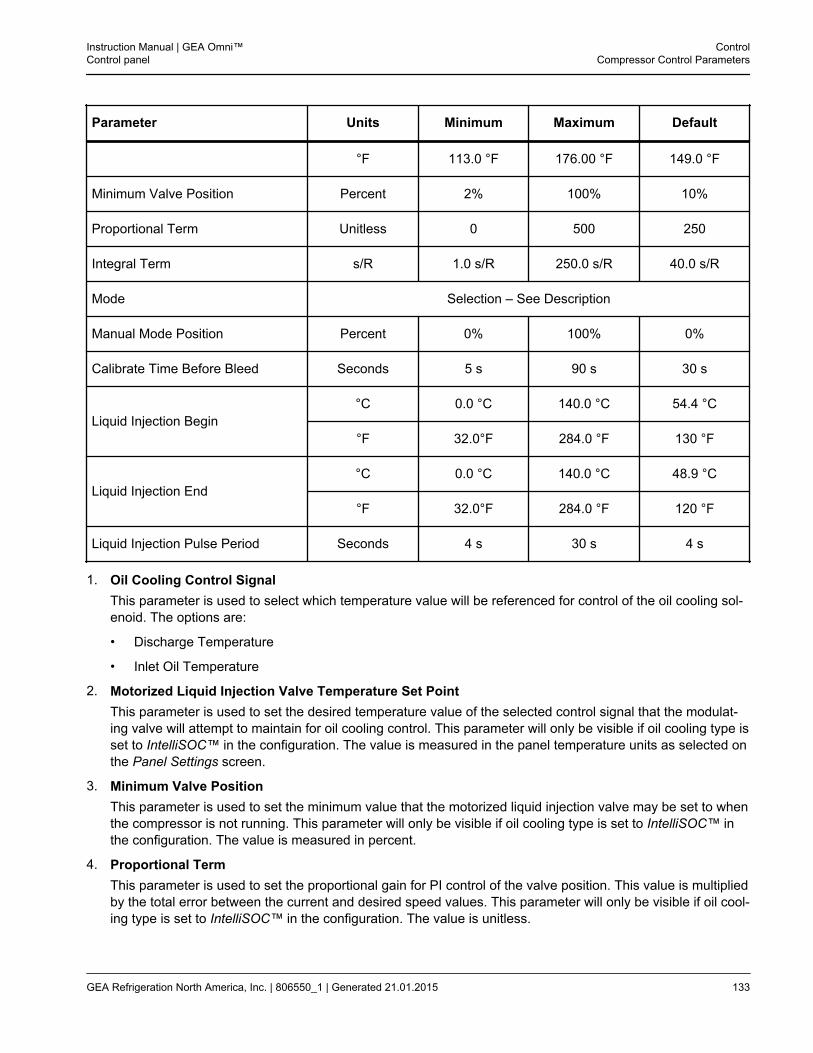
Parameter Units Minimum Maximum Default
°F 113.0 °F 176.00 °F 149.0 °F
Minimum Valve Position Percent 2% 100% 10%
Proportional Term Unitless 0 500 250
Integral Term s/R 1.0 s/R 250.0 s/R 40.0 s/R
Mode Selection – See Description
Manual Mode Position Percent 0% 100% 0%
Calibrate Time Before Bleed Seconds 5 s 90 s 30 s
Liquid Injection Begin°C 0.0 °C 140.0 °C 54.4 °C
°F 32.0°F 284.0 °F 130 °F
Liquid Injection End°C 0.0 °C 140.0 °C 48.9 °C
°F 32.0°F 284.0 °F 120 °F
Liquid Injection Pulse Period Seconds 4 s 30 s 4 s
1. Oil Cooling Control SignalThis parameter is used to select which temperature value will be referenced for control of the oil cooling sol-enoid. The options are:
• Discharge Temperature
• Inlet Oil Temperature
2. Motorized Liquid Injection Valve Temperature Set PointThis parameter is used to set the desired temperature value of the selected control signal that the modulat-ing valve will attempt to maintain for oil cooling control. This parameter will only be visible if oil cooling type isset to IntelliSOC™ in the configuration. The value is measured in the panel temperature units as selected onthe Panel Settings screen.
3. Minimum Valve PositionThis parameter is used to set the minimum value that the motorized liquid injection valve may be set to whenthe compressor is not running. This parameter will only be visible if oil cooling type is set to IntelliSOC™ inthe configuration. The value is measured in percent.
4. Proportional TermThis parameter is used to set the proportional gain for PI control of the valve position. This value is multipliedby the total error between the current and desired speed values. This parameter will only be visible if oil cool-ing type is set to IntelliSOC™ in the configuration. The value is unitless.
Instruction Manual | GEA Omni™Control panel
ControlCompressor Control Parameters
GEA Refrigeration North America, Inc. | 806550_1 | Generated 21.01.2015 133
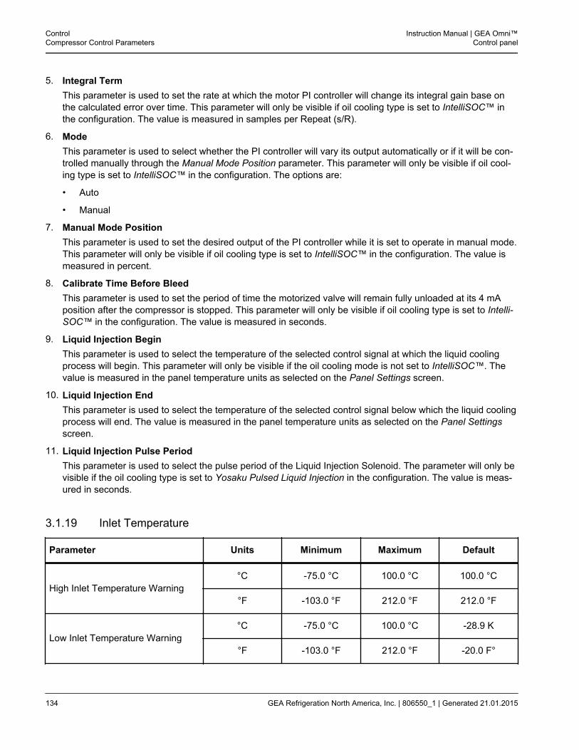
5. Integral TermThis parameter is used to set the rate at which the motor PI controller will change its integral gain base onthe calculated error over time. This parameter will only be visible if oil cooling type is set to IntelliSOC™ inthe configuration. The value is measured in samples per Repeat (s/R).
6. ModeThis parameter is used to select whether the PI controller will vary its output automatically or if it will be con-trolled manually through the Manual Mode Position parameter. This parameter will only be visible if oil cool-ing type is set to IntelliSOC™ in the configuration. The options are:
• Auto
• Manual
7. Manual Mode PositionThis parameter is used to set the desired output of the PI controller while it is set to operate in manual mode.This parameter will only be visible if oil cooling type is set to IntelliSOC™ in the configuration. The value ismeasured in percent.
8. Calibrate Time Before BleedThis parameter is used to set the period of time the motorized valve will remain fully unloaded at its 4 mAposition after the compressor is stopped. This parameter will only be visible if oil cooling type is set to Intelli-SOC™ in the configuration. The value is measured in seconds.
9. Liquid Injection BeginThis parameter is used to select the temperature of the selected control signal at which the liquid coolingprocess will begin. This parameter will only be visible if the oil cooling mode is not set to IntelliSOC™. Thevalue is measured in the panel temperature units as selected on the Panel Settings screen.
10. Liquid Injection EndThis parameter is used to select the temperature of the selected control signal below which the liquid coolingprocess will end. The value is measured in the panel temperature units as selected on the Panel Settingsscreen.
11. Liquid Injection Pulse PeriodThis parameter is used to select the pulse period of the Liquid Injection Solenoid. The parameter will only bevisible if the oil cooling type is set to Yosaku Pulsed Liquid Injection in the configuration. The value is meas-ured in seconds.
3.1.19 Inlet Temperature
Parameter Units Minimum Maximum Default
High Inlet Temperature Warning°C -75.0 °C 100.0 °C 100.0 °C
°F -103.0 °F 212.0 °F 212.0 °F
Low Inlet Temperature Warning°C -75.0 °C 100.0 °C -28.9 K
°F -103.0 °F 212.0 °F -20.0 F°
ControlCompressor Control Parameters
Instruction Manual | GEA Omni™Control panel
134 GEA Refrigeration North America, Inc. | 806550_1 | Generated 21.01.2015
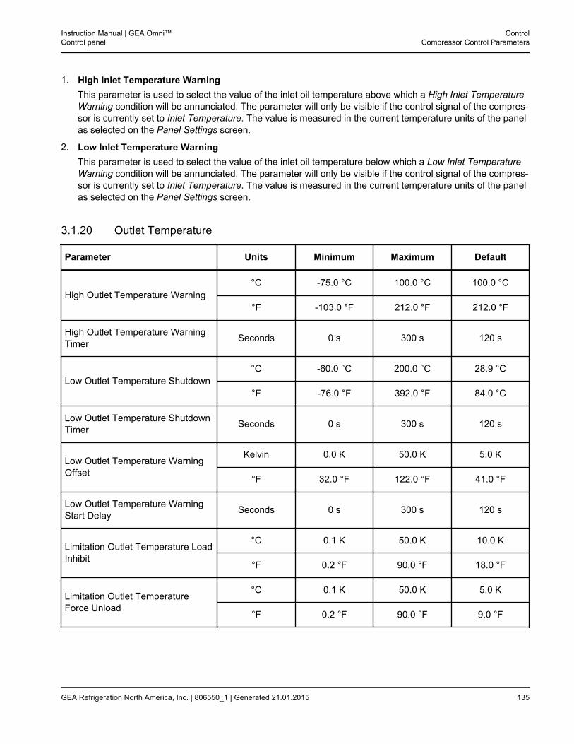
1. High Inlet Temperature WarningThis parameter is used to select the value of the inlet oil temperature above which a High Inlet TemperatureWarning condition will be annunciated. The parameter will only be visible if the control signal of the compres-sor is currently set to Inlet Temperature. The value is measured in the current temperature units of the panelas selected on the Panel Settings screen.
2. Low Inlet Temperature WarningThis parameter is used to select the value of the inlet oil temperature below which a Low Inlet TemperatureWarning condition will be annunciated. The parameter will only be visible if the control signal of the compres-sor is currently set to Inlet Temperature. The value is measured in the current temperature units of the panelas selected on the Panel Settings screen.
3.1.20 Outlet Temperature
Parameter Units Minimum Maximum Default
High Outlet Temperature Warning°C -75.0 °C 100.0 °C 100.0 °C
°F -103.0 °F 212.0 °F 212.0 °F
High Outlet Temperature WarningTimer Seconds 0 s 300 s 120 s
Low Outlet Temperature Shutdown°C -60.0 °C 200.0 °C 28.9 °C
°F -76.0 °F 392.0 °F 84.0 °C
Low Outlet Temperature ShutdownTimer Seconds 0 s 300 s 120 s
Low Outlet Temperature WarningOffset
Kelvin 0.0 K 50.0 K 5.0 K
°F 32.0 °F 122.0 °F 41.0 °F
Low Outlet Temperature WarningStart Delay Seconds 0 s 300 s 120 s
Limitation Outlet Temperature LoadInhibit
°C 0.1 K 50.0 K 10.0 K
°F 0.2 °F 90.0 °F 18.0 °F
Limitation Outlet TemperatureForce Unload
°C 0.1 K 50.0 K 5.0 K
°F 0.2 °F 90.0 °F 9.0 °F
Instruction Manual | GEA Omni™Control panel
ControlCompressor Control Parameters
GEA Refrigeration North America, Inc. | 806550_1 | Generated 21.01.2015 135
1. High Outlet Temperature WarningThis parameter is used to select the value of the inlet oil temperature above which a High Outlet Tempera-ture Warning condition will be annunciated. The parameter will only be visible if the control signal of the com-pressor is currently set to Outlet Temperature. The value is measured in the current temperature units of thepanel as selected on the Panel Settings screen.
2. High Outlet Temperature Warning TimerThis parameter is used to select the period of time that the Outlet Temperature must exceed the value of theHigh Outlet Temperature Warning parameter before the warning will be annunciated. The parameter will onlybe visible if the control signal of the compressor is currently set to Outlet Temperature. The value is meas-ured in seconds.
3. Low Outlet Temperature ShutdownThis parameter is used to select the value of the inlet oil temperature below which a Low Outlet TemperatureShutdown condition will be annunciated. The parameter will only be visible if the control signal of the com-pressor is currently set to Outlet Temperature. The value is measured in the current temperature units of thepanel as selected on the Panel Settings screen.
4. Low Outlet Temperature Shutdown TimerThis parameter is used to select the period of time that the Outlet Temperature must remain below the valueof the Low Outlet Temperature Shutdown parameter before the shutdown will be annunciated. The parame-ter will only be visible if the control signal of the compressor is currently set to Outlet Temperature. The valueis measured in seconds.
5. Low Outlet Temperature Warning OffsetThis parameter is used to set an offset added to the Low Outlet Temperature Shutdown parameter. If theoutlet temperature falls below this calculated value, a Low Outlet Temperature Warning will be annunciated.The warning will only be issued if the compressor is running. The parameter will only be visible if the controlsignal of the compressor is currently set to Outlet Temperature. The value is measured in the panel tempera-ture units as selected on the Panel Settings screen.
6. Low Outlet Temperature Warning Start DelayThis parameter is used to select the amount of time the compressor will be permitted to run after startingbefore a Low Outlet Temperature Warning condition will be annunciated. The parameter will only be visible ifthe control signal of the compressor is currently set to Outlet Temperature. The value is measured in sec-onds.
7. Limitation Outlet Temperature Load InhibitThis parameter is used to set an offset value added to the Low Outlet Temperature Shutdown parameter. Ifthe Outlet Temperature falls below this calculated value, the compressor will be prevented from loading. Theparameter will only be visible if the control signal of the compressor is currently set to Outlet Temperature.The value is measured in the panel temperature units as selected on the Panel Settings screen.
8. Limitation Outlet Temperature Force UnloadThis parameter is used to set an offset value added to the Low Outlet Temperature Shutdown parameter. Ifthe outlet temperature falls below this calculated value, the compressor will be forced to unload. The param-eter will only be visible if the control signal of the compressor is currently set to Outlet Temperature. Thevalue is measured in the panel temperature units as selected on the Panel Settings screen.
ControlCompressor Control Parameters
Instruction Manual | GEA Omni™Control panel
136 GEA Refrigeration North America, Inc. | 806550_1 | Generated 21.01.2015
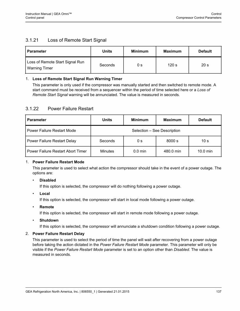
3.1.21 Loss of Remote Start Signal
Parameter Units Minimum Maximum Default
Loss of Remote Start Signal RunWarning Timer
Seconds 0 s 120 s 20 s
1. Loss of Remote Start Signal Run Warning TimerThis parameter is only used if the compressor was manually started and then switched to remote mode. Astart command must be received from a sequencer within the period of time selected here or a Loss ofRemote Start Signal warning will be annunciated. The value is measured in seconds.
3.1.22 Power Failure Restart
Parameter Units Minimum Maximum Default
Power Failure Restart Mode Selection – See Description
Power Failure Restart Delay Seconds 0 s 8000 s 10 s
Power Failure Restart Abort Timer Minutes 0.0 min 480.0 min 10.0 min
1. Power Failure Restart ModeThis parameter is used to select what action the compressor should take in the event of a power outage. Theoptions are:
• DisabledIf this option is selected, the compressor will do nothing following a power outage.
• LocalIf this option is selected, the compressor will start in local mode following a power outage.
• RemoteIf this option is selected, the compressor will start in remote mode following a power outage.
• ShutdownIf this option is selected, the compressor will annunciate a shutdown condition following a power outage.
2. Power Failure Restart DelayThis parameter is used to select the period of time the panel will wait after recovering from a power outagebefore taking the action dictated in the Power Failure Restart Mode parameter. This parameter will only bevisible if the Power Failure Restart Mode parameter is set to an option other than Disabled. The value ismeasured in seconds.
Instruction Manual | GEA Omni™Control panel
ControlCompressor Control Parameters
GEA Refrigeration North America, Inc. | 806550_1 | Generated 21.01.2015 137
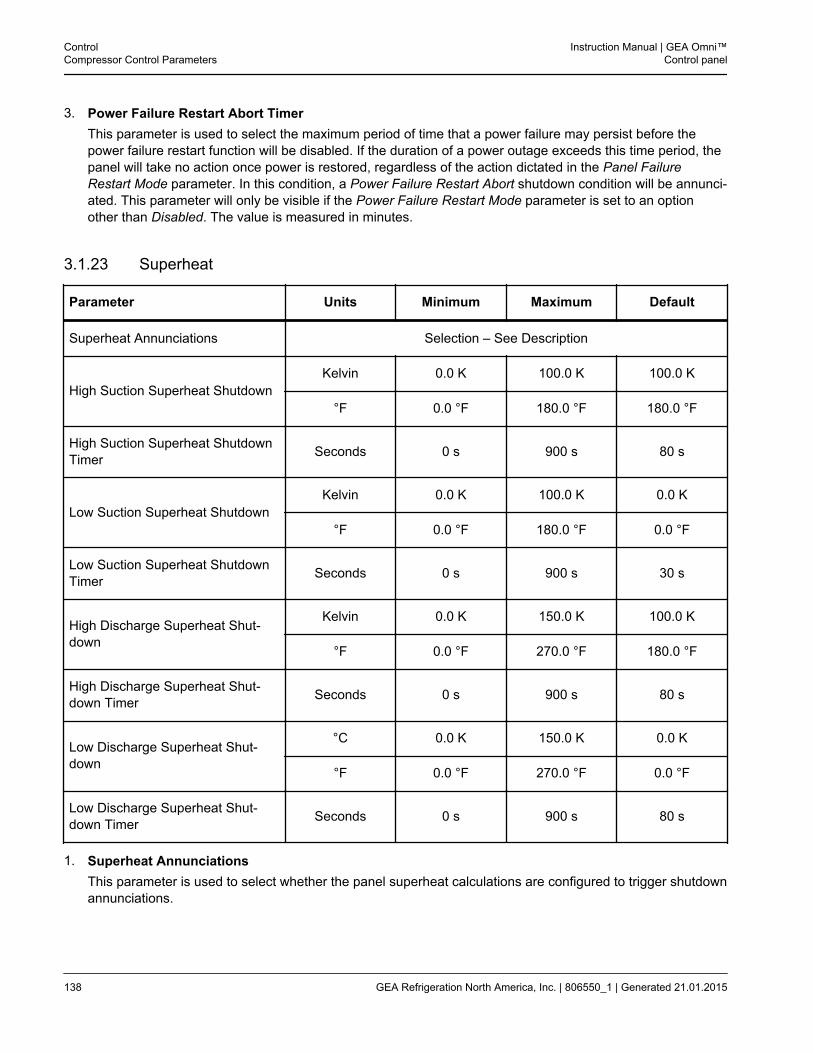
3. Power Failure Restart Abort TimerThis parameter is used to select the maximum period of time that a power failure may persist before thepower failure restart function will be disabled. If the duration of a power outage exceeds this time period, thepanel will take no action once power is restored, regardless of the action dictated in the Panel FailureRestart Mode parameter. In this condition, a Power Failure Restart Abort shutdown condition will be annunci-ated. This parameter will only be visible if the Power Failure Restart Mode parameter is set to an optionother than Disabled. The value is measured in minutes.
3.1.23 Superheat
Parameter Units Minimum Maximum Default
Superheat Annunciations Selection – See Description
High Suction Superheat ShutdownKelvin 0.0 K 100.0 K 100.0 K
°F 0.0 °F 180.0 °F 180.0 °F
High Suction Superheat ShutdownTimer Seconds 0 s 900 s 80 s
Low Suction Superheat ShutdownKelvin 0.0 K 100.0 K 0.0 K
°F 0.0 °F 180.0 °F 0.0 °F
Low Suction Superheat ShutdownTimer Seconds 0 s 900 s 30 s
High Discharge Superheat Shut-down
Kelvin 0.0 K 150.0 K 100.0 K
°F 0.0 °F 270.0 °F 180.0 °F
High Discharge Superheat Shut-down Timer Seconds 0 s 900 s 80 s
Low Discharge Superheat Shut-down
°C 0.0 K 150.0 K 0.0 K
°F 0.0 °F 270.0 °F 0.0 °F
Low Discharge Superheat Shut-down Timer Seconds 0 s 900 s 80 s
1. Superheat AnnunciationsThis parameter is used to select whether the panel superheat calculations are configured to trigger shutdownannunciations.
ControlCompressor Control Parameters
Instruction Manual | GEA Omni™Control panel
138 GEA Refrigeration North America, Inc. | 806550_1 | Generated 21.01.2015
2. High Suction Superheat ShutdownThis parameter is used to select the Suction Superheat temperature above which a High Suction SuperheatShutdown will be annunciated. This parameter will only be visible if the Superheat Annunciations parameterhas been set to Enabled. The shutdown will only be issued if the compressor is starting or running. Thevalue is measured in the panel temperature units as selected on the Panel Settings screen.
3. High Suction Superheat Shutdown TimerThis parameter is used to select the period of time that the Suction Superheat value must remain above thevalue of the High Suction Superheat parameter before a High Suction Superheat Shutdown is annunciated.This parameter will only be visible if the Superheat Annunciations parameter has been set to Enabled. Thevalue is measured in seconds.
4. Low Suction Superheat ShutdownThis parameter is used to select the Suction Superheat temperature below which a Low Suction SuperheatShutdown will be annunciated. This parameter will only be visible if the Superheat Annunciations parameterhas been set to Enabled. The shutdown will only be issued if the compressor is starting or running. Thevalue is measured in the panel temperature units as selected on the Panel Settings screen.
5. Low Suction Superheat Shutdown TimerThis parameter is used to select the period of time that the Suction Superheat value must remain below thevalue of the Low Suction Superheat parameter before a Low Suction Superheat Shutdown is annunciated.This parameter will only be visible if the Superheat Annunciations parameter has been set to Enabled. Thevalue is measured in seconds.
6. High Discharge Superheat ShutdownThis parameter is used to select the Discharge Superheat temperature above which a High DischargeSuperheat Shutdown will be annunciated. This parameter will only be visible if the Superheat Annunciationsparameter has been set to Enabled. The shutdown will only be issued if the compressor is starting or run-ning. The value is measured in the panel temperature units as selected on the Panel Settings screen.
7. High Discharge Superheat Shutdown TimerThis parameter is used to select the period of time that the Discharge Superheat value must remain abovethe value of the High Discharge Superheat parameter before a High Discharge Superheat Shutdown isannunciated. This parameter will only be visible if the Superheat Annunciations parameter has been set toEnabled. The value is measured in seconds.
8. Low Discharge Superheat ShutdownThis parameter is used to select the Discharge Superheat temperature below which a Low Discharge Super-heat Shutdown will be annunciated. This parameter will only be visible if the Superheat Annunciationsparameter has been set to Enabled. The shutdown will only be issued if the compressor is starting or run-ning. The value is measured in the panel temperature units as selected on the Panel Settings screen.
9. Low Discharge Superheat Shutdown TimerThis parameter is used to select the period of time that the Discharge Superheat value must remain belowthe value of the Low Discharge Superheat parameter before a Low Discharge Superheat Shutdown isannunciated. This parameter will only be visible if the Superheat Annunciations parameter has been set toEnabled. The value is measured in seconds.
Instruction Manual | GEA Omni™Control panel
ControlCompressor Control Parameters
GEA Refrigeration North America, Inc. | 806550_1 | Generated 21.01.2015 139
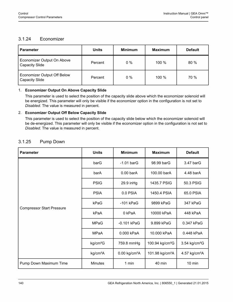
3.1.24 Economizer
Parameter Units Minimum Maximum Default
Economizer Output On AboveCapacity Slide Percent 0 % 100 % 80 %
Economizer Output Off BelowCapacity Slide Percent 0 % 100 % 70 %
1. Economizer Output On Above Capacity SlideThis parameter is used to select the position of the capacity slide above which the economizer solenoid willbe energized. This parameter will only be visible if the economizer option in the configuration is not set toDisabled. The value is measured in percent.
2. Economizer Output Off Below Capacity SlideThis parameter is used to select the position of the capacity slide below which the economizer solenoid willbe de-energized. This parameter will only be visible if the economizer option in the configuration is not set toDisabled. The value is measured in percent.
3.1.25 Pump Down
Parameter Units Minimum Maximum Default
Compressor Start Pressure
barG -1.01 barG 98.99 barG 3.47 barG
barA 0.00 barA 100.00 barA 4.48 barA
PSIG 29.9 inHg 1435.7 PSIG 50.3 PSIG
PSIA 0.0 PSIA 1450.4 PSIA 65.0 PSIA
kPaG -101 kPaG 9899 kPaG 347 kPaG
kPaA 0 kPaA 10000 kPaA 448 kPaA
MPaG -0.101 kPaG 9.899 kPaG 0.347 kPaG
MPaA 0.000 kPaA 10.000 kPaA 0.448 kPaA
kg/cm²G 759.8 mmHg 100.94 kg/cm²G 3.54 kg/cm²G
kg/cm²A 0.00 kg/cm²A 101.98 kg/cm²A 4.57 kg/cm²A
Pump Down Maximum Time Minutes 1 min 40 min 10 min
ControlCompressor Control Parameters
Instruction Manual | GEA Omni™Control panel
140 GEA Refrigeration North America, Inc. | 806550_1 | Generated 21.01.2015
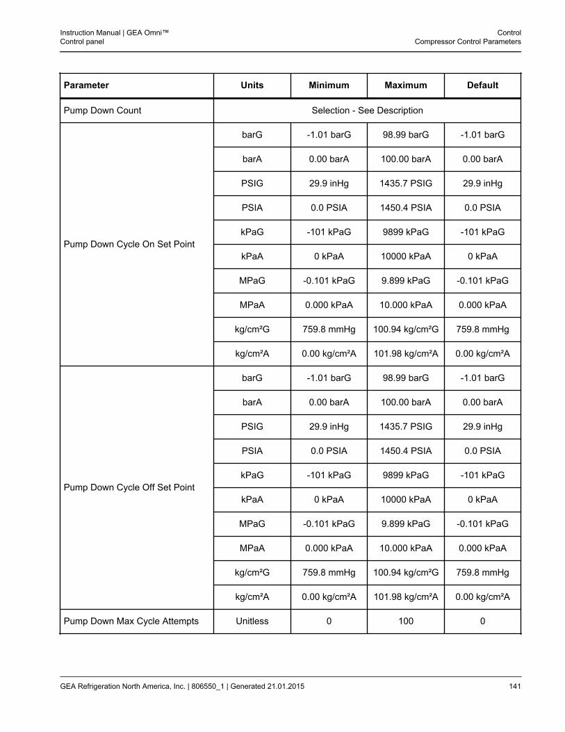
Parameter Units Minimum Maximum Default
Pump Down Count Selection - See Description
Pump Down Cycle On Set Point
barG -1.01 barG 98.99 barG -1.01 barG
barA 0.00 barA 100.00 barA 0.00 barA
PSIG 29.9 inHg 1435.7 PSIG 29.9 inHg
PSIA 0.0 PSIA 1450.4 PSIA 0.0 PSIA
kPaG -101 kPaG 9899 kPaG -101 kPaG
kPaA 0 kPaA 10000 kPaA 0 kPaA
MPaG -0.101 kPaG 9.899 kPaG -0.101 kPaG
MPaA 0.000 kPaA 10.000 kPaA 0.000 kPaA
kg/cm²G 759.8 mmHg 100.94 kg/cm²G 759.8 mmHg
kg/cm²A 0.00 kg/cm²A 101.98 kg/cm²A 0.00 kg/cm²A
Pump Down Cycle Off Set Point
barG -1.01 barG 98.99 barG -1.01 barG
barA 0.00 barA 100.00 barA 0.00 barA
PSIG 29.9 inHg 1435.7 PSIG 29.9 inHg
PSIA 0.0 PSIA 1450.4 PSIA 0.0 PSIA
kPaG -101 kPaG 9899 kPaG -101 kPaG
kPaA 0 kPaA 10000 kPaA 0 kPaA
MPaG -0.101 kPaG 9.899 kPaG -0.101 kPaG
MPaA 0.000 kPaA 10.000 kPaA 0.000 kPaA
kg/cm²G 759.8 mmHg 100.94 kg/cm²G 759.8 mmHg
kg/cm²A 0.00 kg/cm²A 101.98 kg/cm²A 0.00 kg/cm²A
Pump Down Max Cycle Attempts Unitless 0 100 0
Instruction Manual | GEA Omni™Control panel
ControlCompressor Control Parameters
GEA Refrigeration North America, Inc. | 806550_1 | Generated 21.01.2015 141
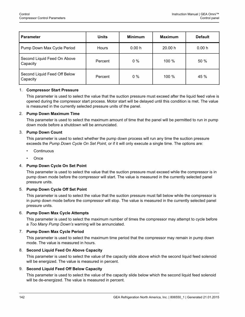
Parameter Units Minimum Maximum Default
Pump Down Max Cycle Period Hours 0.00 h 20.00 h 0.00 h
Second Liquid Feed On AboveCapacity Percent 0 % 100 % 50 %
Second Liquid Feed Off BelowCapacity Percent 0 % 100 % 45 %
1. Compressor Start PressureThis parameter is used to select the value that the suction pressure must exceed after the liquid feed valve isopened during the compressor start process. Motor start will be delayed until this condition is met. The valueis measured in the currently selected pressure units of the panel.
2. Pump Down Maximum TimeThis parameter is used to select the maximum amount of time that the panel will be permitted to run in pumpdown mode before a shutdown will be annunciated.
3. Pump Down CountThis parameter is used to select whether the pump down process will run any time the suction pressureexceeds the Pump Down Cycle On Set Point, or if it will only execute a single time. The options are:
• Continuous
• Once
4. Pump Down Cycle On Set PointThis parameter is used to select the value that the suction pressure must exceed while the compressor is inpump down mode before the compressor will start. The value is measured in the currently selected panelpressure units.
5. Pump Down Cycle Off Set PointThis parameter is used to select the value that the suction pressure must fall below while the compressor isin pump down mode before the compressor will stop. The value is measured in the currently selected panelpressure units.
6. Pump Down Max Cycle AttemptsThis parameter is used to select the maximum number of times the compressor may attempt to cycle beforea Too Many Pump Down’s warning will be annunciated.
7. Pump Down Max Cycle PeriodThis parameter is used to select the maximum time period that the compressor may remain in pump downmode. The value is measured in hours.
8. Second Liquid Feed On Above CapacityThis parameter is used to select the value of the capacity slide above which the second liquid feed solenoidwill be energized. The value is measured in percent.
9. Second Liquid Feed Off Below CapacityThis parameter is used to select the value of the capacity slide below which the second liquid feed solenoidwill be de-energized. The value is measured in percent.
ControlCompressor Control Parameters
Instruction Manual | GEA Omni™Control panel
142 GEA Refrigeration North America, Inc. | 806550_1 | Generated 21.01.2015
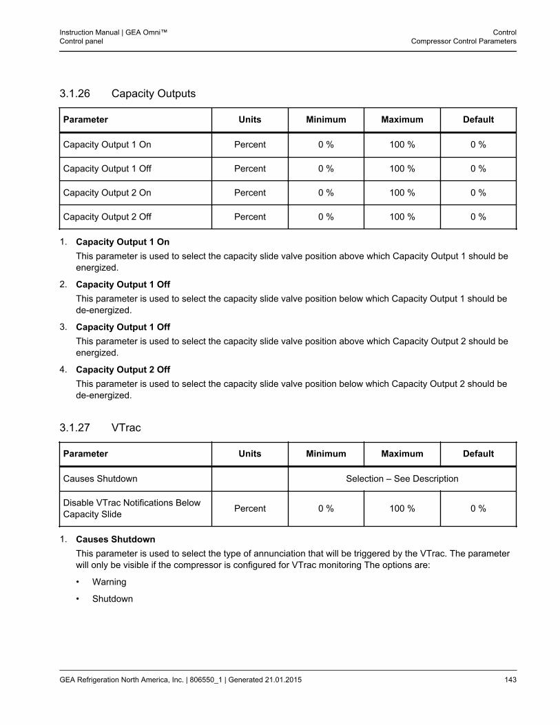
3.1.26 Capacity Outputs
Parameter Units Minimum Maximum Default
Capacity Output 1 On Percent 0 % 100 % 0 %
Capacity Output 1 Off Percent 0 % 100 % 0 %
Capacity Output 2 On Percent 0 % 100 % 0 %
Capacity Output 2 Off Percent 0 % 100 % 0 %
1. Capacity Output 1 OnThis parameter is used to select the capacity slide valve position above which Capacity Output 1 should beenergized.
2. Capacity Output 1 OffThis parameter is used to select the capacity slide valve position below which Capacity Output 1 should bede-energized.
3. Capacity Output 1 OffThis parameter is used to select the capacity slide valve position above which Capacity Output 2 should beenergized.
4. Capacity Output 2 OffThis parameter is used to select the capacity slide valve position below which Capacity Output 2 should bede-energized.
3.1.27 VTrac
Parameter Units Minimum Maximum Default
Causes Shutdown Selection – See Description
Disable VTrac Notifications BelowCapacity Slide Percent 0 % 100 % 0 %
1. Causes ShutdownThis parameter is used to select the type of annunciation that will be triggered by the VTrac. The parameterwill only be visible if the compressor is configured for VTrac monitoring The options are:
• Warning
• Shutdown
Instruction Manual | GEA Omni™Control panel
ControlCompressor Control Parameters
GEA Refrigeration North America, Inc. | 806550_1 | Generated 21.01.2015 143
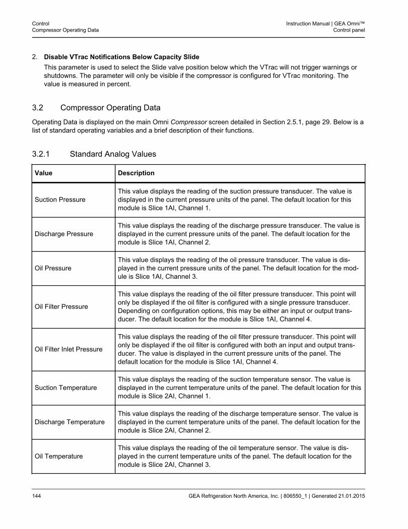
2. Disable VTrac Notifications Below Capacity SlideThis parameter is used to select the Slide valve position below which the VTrac will not trigger warnings orshutdowns. The parameter will only be visible if the compressor is configured for VTrac monitoring. Thevalue is measured in percent.
3.2 Compressor Operating Data
Operating Data is displayed on the main Omni Compressor screen detailed in Section 2.5.1, page 29. Below is alist of standard operating variables and a brief description of their functions.
3.2.1 Standard Analog Values
Value Description
Suction PressureThis value displays the reading of the suction pressure transducer. The value isdisplayed in the current pressure units of the panel. The default location for thismodule is Slice 1AI, Channel 1.
Discharge PressureThis value displays the reading of the discharge pressure transducer. The value isdisplayed in the current pressure units of the panel. The default location for themodule is Slice 1AI, Channel 2.
Oil PressureThis value displays the reading of the oil pressure transducer. The value is dis-played in the current pressure units of the panel. The default location for the mod-ule is Slice 1AI, Channel 3.
Oil Filter Pressure
This value displays the reading of the oil filter pressure transducer. This point willonly be displayed if the oil filter is configured with a single pressure transducer.Depending on configuration options, this may be either an input or output trans-ducer. The default location for the module is Slice 1AI, Channel 4.
Oil Filter Inlet Pressure
This value displays the reading of the oil filter pressure transducer. This point willonly be displayed if the oil filter is configured with both an input and output trans-ducer. The value is displayed in the current pressure units of the panel. Thedefault location for the module is Slice 1AI, Channel 4.
Suction TemperatureThis value displays the reading of the suction temperature sensor. The value isdisplayed in the current temperature units of the panel. The default location for thismodule is Slice 2AI, Channel 1.
Discharge TemperatureThis value displays the reading of the discharge temperature sensor. The value isdisplayed in the current temperature units of the panel. The default location for themodule is Slice 2AI, Channel 2.
Oil TemperatureThis value displays the reading of the oil temperature sensor. The value is dis-played in the current temperature units of the panel. The default location for themodule is Slice 2AI, Channel 3.
ControlCompressor Operating Data
Instruction Manual | GEA Omni™Control panel
144 GEA Refrigeration North America, Inc. | 806550_1 | Generated 21.01.2015
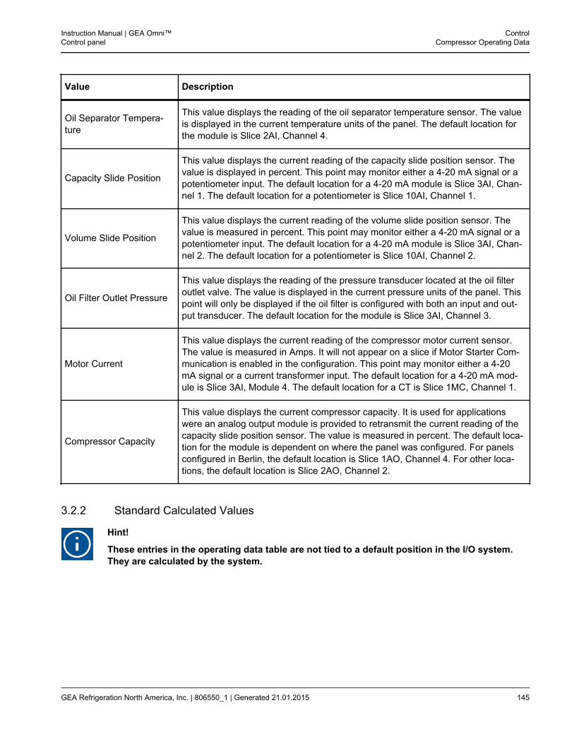
Value Description
Oil Separator Tempera-ture
This value displays the reading of the oil separator temperature sensor. The valueis displayed in the current temperature units of the panel. The default location forthe module is Slice 2AI, Channel 4.
Capacity Slide Position
This value displays the current reading of the capacity slide position sensor. Thevalue is displayed in percent. This point may monitor either a 4-20 mA signal or apotentiometer input. The default location for a 4-20 mA module is Slice 3AI, Chan-nel 1. The default location for a potentiometer is Slice 10AI, Channel 1.
Volume Slide Position
This value displays the current reading of the volume slide position sensor. Thevalue is measured in percent. This point may monitor either a 4-20 mA signal or apotentiometer input. The default location for a 4-20 mA module is Slice 3AI, Chan-nel 2. The default location for a potentiometer is Slice 10AI, Channel 2.
Oil Filter Outlet Pressure
This value displays the reading of the pressure transducer located at the oil filteroutlet valve. The value is displayed in the current pressure units of the panel. Thispoint will only be displayed if the oil filter is configured with both an input and out-put transducer. The default location for the module is Slice 3AI, Channel 3.
Motor Current
This value displays the current reading of the compressor motor current sensor.The value is measured in Amps. It will not appear on a slice if Motor Starter Com-munication is enabled in the configuration. This point may monitor either a 4-20mA signal or a current transformer input. The default location for a 4-20 mA mod-ule is Slice 3AI, Module 4. The default location for a CT is Slice 1MC, Channel 1.
Compressor Capacity
This value displays the current compressor capacity. It is used for applicationswere an analog output module is provided to retransmit the current reading of thecapacity slide position sensor. The value is measured in percent. The default loca-tion for the module is dependent on where the panel was configured. For panelsconfigured in Berlin, the default location is Slice 1AO, Channel 4. For other loca-tions, the default location is Slice 2AO, Channel 2.
3.2.2 Standard Calculated Values
Hint!
These entries in the operating data table are not tied to a default position in the I/O system.They are calculated by the system.
Instruction Manual | GEA Omni™Control panel
ControlCompressor Operating Data
GEA Refrigeration North America, Inc. | 806550_1 | Generated 21.01.2015 145
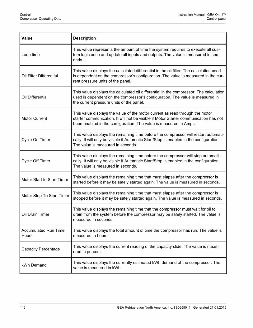
Value Description
Loop timeThis value represents the amount of time the system requires to execute all cus-tom logic once and update all inputs and outputs. The value is measured in sec-onds.
Oil Filter DifferentialThis value displays the calculated differential in the oil filter. The calculation usedis dependent on the compressor’s configuration. The value is measured in the cur-rent pressure units of the panel.
Oil DifferentialThis value displays the calculated oil differential in the compressor. The calculationused is dependent on the compressor’s configuration. The value is measured inthe current pressure units of the panel.
Motor CurrentThis value displays the value of the motor current as read through the motorstarter communication. It will not be visible if Motor Starter communication has notbeen enabled in the configuration. The value is measured in Amps.
Cycle On TimerThis value displays the remaining time before the compressor will restart automati-cally. It will only be visible if Automatic Start/Stop is enabled in the configuration.The value is measured in seconds.
Cycle Off TimerThis value displays the remaining time before the compressor will stop automati-cally. It will only be visible if Automatic Start/Stop is enabled in the configuration.The value is measured in seconds.
Motor Start to Start Timer This value displays the remaining time that must elapse after the compressor isstarted before it may be safely started again. The value is measured in seconds.
Motor Stop To Start Timer This value displays the remaining time that must elapse after the compressor isstopped before it may be safely started again. The value is measured in seconds.
Oil Drain TimerThis value displays the remaining time that the compressor must wait for oil todrain from the system before the compressor may be safely started. The value ismeasured in seconds.
Accumulated Run TimeHours
This value displays the total amount of time the compressor has run. The value ismeasured in hours.
Capacity Percentage This value displays the current reading of the capacity slide. The value is meas-ured in percent.
kWh Demand This value displays the currently estimated kWh demand of the compressor. Thevalue is measured in kWh.
ControlCompressor Operating Data
Instruction Manual | GEA Omni™Control panel
146 GEA Refrigeration North America, Inc. | 806550_1 | Generated 21.01.2015
3.2.3 Standard Digital Values
Value Description
Emergency Stop
This data point monitors the status of the Emergency Stop switch. It will be ener-gized for normal panel operation. If this point ever becomes de-energized, anEmergency Stop shutdown will be triggered. The states are On and Off. Thedefault location of this module is Slice 1DI, Channel 1.
Compressor Interlock
This data point monitors the status of the compressor run feedback module. It willbe energized while the compressor is running, and de-energized while the com-pressor is stopped. If this point ever becomes de-energized while the compressoris running, or energized while the compressor is stopped, an interlock alarm condi-tion will be triggered. The states are On and Off. The default location of this mod-ule is Slice 1DI, Channel 2.
Oil Pump Interlock
This data point monitors the status of the oil pump run feedback module. It will beenergized while the oil pump is running, and de-energized while the oil pump isstopped. If this point ever becomes de-energized while the oil pump is running, orenergized while the oil pump is stopped, an interlock alarm condition will be trig-gered. The states are On and Off. The default location of this module is Slice 1DI,Channel 3.
External Unload
This data point monitors the status of a remote compressor control device. Thismodule will only be used if the panel is operating in Remote Mode. It will be ener-gized to remotely instruct the compressor to load, and de-energized at all othertimes. The states are On and Off. The default location of this module is Slice 1DI,Channel 4.
External Load
This data point monitors the status of a remote compressor control device. Thismodule will only be used if the panel is operating in Remote Mode. It will be ener-gized to remotely instruct the compressor to unload, and de-energized at all othertimes. The states are On and Off. The default location of this module is Slice 1DI,Channel 5.
External Start/Stop
This data point monitors the status of a remote compressor control device. Thismodule will only be used if the panel is operating in Remote Mode. It will be ener-gized to remotely instruct the compressor to start, and de-energized to instruct it tostop. The states are On and Off. The default location of this module is Slice 1DI,Channel 6.
Start Permissive
This data point monitors whether the compressor is currently allowed to start. Aslong as it is energized, the compressor may start normally, otherwise any instruc-tion to start will be ignored. The states are On and Off. The default location of thismodule is Slice 1DI, Channel 7.
Instruction Manual | GEA Omni™Control panel
ControlCompressor Operating Data
GEA Refrigeration North America, Inc. | 806550_1 | Generated 21.01.2015 147
Value Description
Low Oil Level
This data point monitors an oil level float switch. It will be energized for normaloperation of the panel, and will only de-energize if the liquid level falls below thelevel of the switch. The states are On and Off. The default location of this moduleis Slice 1DI, Channel 8.
Aux Shutdown
This data point monitors a miscellaneous shutdown condition for the compressor.It will be energized for normal panel operation. If this point ever becomes de-ener-gized, a shutdown annunciation will be triggered. The states are On and Off. Thedefault location of this module is Slice 2DI, Channel 1.
Aux Warning
This data point monitors a miscellaneous warning condition for the compressor. Itwill be energized for normal panel operation. If this point ever becomes de-ener-gized, a warning annunciation will be triggered. The states are On and Off. Thedefault location of this module is Slice 2DI, Channel 2.
Set Point Select
This data point is used to control which set point is currently being used. This mod-ule will only be enabled if the compressor is configured for multiple set points. Setpoint 1 will be enabled if the module is energized, and set point 2 will be enabled ifit is de-energized. The states are On and Off. The default location of this module isSlice 2DI, Channel 5.
Auxiliary Shutdown #2
This data point monitors a miscellaneous shutdown condition for the compressor.It will be energized for normal panel operation. If this point ever becomes de-ener-gized, a shutdown annunciation will be triggered. The states are On and Off. Thedefault location of this module is Slice 2DI, Channel 6.
Aux Warning #2
This data point monitors a miscellaneous warning condition for the compressor. Itwill be energized for normal panel operation. If this point ever becomes de-ener-gized, a warning annunciation will be triggered. The states are On and Off. Thedefault location of this module is Slice 2DI, Channel 7.
Compressor Motor Start
This data point controls the starter for the compressor motor. It will energize fortwo seconds when the compressor is instructed to start, and will be de-energizedat all other times. The states are On and Off. The default location of this module isSlice 1DO, Channel 1
Oil Pump Motor Start
This data point controls the starter for the oil pump motor. It will be energizedwhenever the oil pump is instructed to run, and will be de-energized at all othertimes. The states are On and Off. The default location of this module is Slice 1DO,Channel 2.
Unload Solenoid
This data point controls the compressor unload solenoid. It will be energized when-ever the compressor is unloading the solenoid, and will be de-energized at allother times. The states are On and Off. The default location of this module is Slice1DO, Channel 3.
ControlCompressor Operating Data
Instruction Manual | GEA Omni™Control panel
148 GEA Refrigeration North America, Inc. | 806550_1 | Generated 21.01.2015
Value Description
Load Solenoid
This data point controls the compressor load solenoid. It will be energized when-ever the compressor is loading the solenoid, and will be de-energized at all othertimes. The states are On and Off. The default location of this module is Slice 1DO,Channel 4.
Shutdown Status
This data point displays whether the panel has entered a shutdown state. It will beenergized for normal panel operation and will de-energize any time a shutdowncondition is annunciated. The states are On and Off. The default location of thismodule is Slice 1DO, Channel 7.
Ready For Remote
This data point controls whether the compressor is currently permitted to run viaexternal control from a remote device. It will be energized when remote mode ispermitted and disabled at all other times. The states are On and Off. The defaultlocation of this module is Slice 1DO, Channel 8.
Oil Cooling
This data point controls the oil cooing solenoid. It will be energized whenever theoil cooling should be energized as determined by the type of oil cooling system,and de-energized at any other time. The states are On and Off. The default loca-tion of this module is Slice 2DO, Channel 1.
Unloaded StartThis data point displays whether the compressor has initiated the unload cycle.The states are On and Off. The default location of this module is Slice 2DO, Chan-nel 5.
Oil Separator HeaterThis data point displays the current status of the heater for the oil separator. It willbe energized The states are On and Off. The default location of this module isSlice 2DO, Channel 7.
Warning Status
This data point displays whether the panel has entered a warning state. It will beenergized for normal panel operation and will de-energize any time a warning con-dition is annunciated. The states are On and Off. The default location of this mod-ule is Slice 2DO, Channel 8.
Motor Start To Start TimerActive
This data point displays whether the motor start to start timer is currently active. Itwill be energized while the timer is running and de-energized at all other times.The states are On and Off. The default location of this module is Slice 3DO, Chan-nel 1.
Green/White Lamp
This data point displays the green or white lamp on the panel light stack. If thepanel is running and no annunciations have been triggered, this point will be ener-gized. Otherwise, it will be de-energized. The states are On and Off. The defaultlocation of this module is Slice 3DO, Channel 6.
Instruction Manual | GEA Omni™Control panel
ControlCompressor Operating Data
GEA Refrigeration North America, Inc. | 806550_1 | Generated 21.01.2015 149
Value Description
Yellow Lamp
This data point displays the status of the yellow lamp on the panel light stack. If thepanel has annunciated a warning condition, this point will be energized. Otherwise,it will be de-energized. The states are On and Off. The default location of this mod-ule is Slice 3DO, Channel 7.
Red Lamp
This data point displays the status of the yellow lamp on the panel light stack. If thepanel has annunciated a shutdown condition, this point will be energized. Other-wise, it will be de-energized. The states are On and Off. The default location of thismodule is Slice 3DO, Channel 8.
ControlCompressor Operating Data
Instruction Manual | GEA Omni™Control panel
150 GEA Refrigeration North America, Inc. | 806550_1 | Generated 21.01.2015
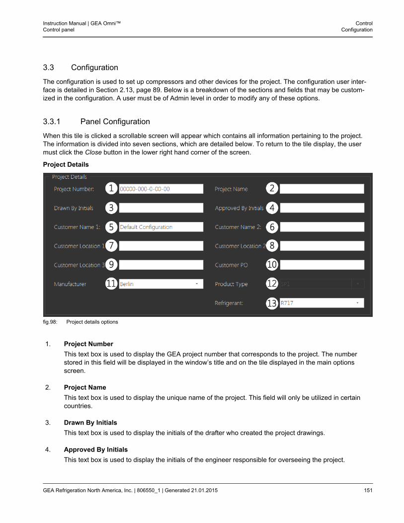
3.3 Configuration
The configuration is used to set up compressors and other devices for the project. The configuration user inter-face is detailed in Section 2.13, page 89. Below is a breakdown of the sections and fields that may be custom-ized in the configuration. A user must be of Admin level in order to modify any of these options.
3.3.1 Panel Configuration
When this tile is clicked a scrollable screen will appear which contains all information pertaining to the project.The information is divided into seven sections, which are detailed below. To return to the tile display, the usermust click the Close button in the lower right hand corner of the screen.
Project Details
fig.98: Project details options
1. Project NumberThis text box is used to display the GEA project number that corresponds to the project. The numberstored in this field will be displayed in the window’s title and on the tile displayed in the main optionsscreen.
2. Project NameThis text box is used to display the unique name of the project. This field will only be utilized in certaincountries.
3. Drawn By InitialsThis text box is used to display the initials of the drafter who created the project drawings.
4. Approved By InitialsThis text box is used to display the initials of the engineer responsible for overseeing the project.
Instruction Manual | GEA Omni™Control panel
ControlConfiguration
GEA Refrigeration North America, Inc. | 806550_1 | Generated 21.01.2015 151
5. Customer Name 1This text box is used to display the primary name of the organization that is to receive the product. Thecontents of this field will be displayed in the window’s title and on the tile displayed in the main optionsscreen.
6 Customer Name 2This text box is used to display supplemental information regarding the name of the customer may befilled in here. This information will not appear in the title bar.
7. Customer Location 1This text box is used to display basic information regarding the location of the customer to receive theproduct.
8. Customer Location 2This text box is used to display supplemental information regarding the location of the customer may beentered here.
9. Customer Location 3This text box is used to display supplemental information regarding the location of the customer may beentered here.
10. Customer POThis text box is used to display customer provided purchase order information.
11. ManufacturerThis drop down list is used to select the location where the panel was constructed. The options are:
• York
• Suzhou
• Berlin
12. Product TypeThis drop down list is used to select the type of package controlled by the panel. This option may not bemodified in the field. Some common options include:
• SP1
• SP2
• SPduo
ControlConfiguration
Instruction Manual | GEA Omni™Control panel
152 GEA Refrigeration North America, Inc. | 806550_1 | Generated 21.01.2015
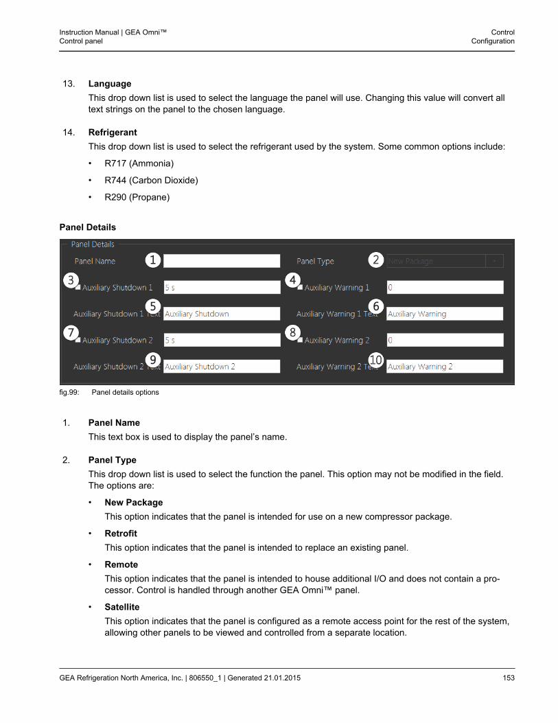
13. LanguageThis drop down list is used to select the language the panel will use. Changing this value will convert alltext strings on the panel to the chosen language.
14. RefrigerantThis drop down list is used to select the refrigerant used by the system. Some common options include:
• R717 (Ammonia)
• R744 (Carbon Dioxide)
• R290 (Propane)
Panel Details
fig.99: Panel details options
1. Panel NameThis text box is used to display the panel’s name.
2. Panel TypeThis drop down list is used to select the function the panel. This option may not be modified in the field.The options are:
• New PackageThis option indicates that the panel is intended for use on a new compressor package.
• RetrofitThis option indicates that the panel is intended to replace an existing panel.
• RemoteThis option indicates that the panel is intended to house additional I/O and does not contain a pro-cessor. Control is handled through another GEA Omni™ panel.
• SatelliteThis option indicates that the panel is configured as a remote access point for the rest of the system,allowing other panels to be viewed and controlled from a separate location.
Instruction Manual | GEA Omni™Control panel
ControlConfiguration
GEA Refrigeration North America, Inc. | 806550_1 | Generated 21.01.2015 153
3. Auxiliary ShutdownThis check box is used to select if the panel will be equipped with a custom I/O shutdown point. The textbox displayed to the right of the check box displays the delay that will elapse before the annunciation istriggered.
4. Auxiliary WarningThis check box is used to select if the panel will be equipped with a custom I/O warning point. The textbox displayed to the right of the check box displays the delay that will elapse before the annunciation istriggered.
5. Auxiliary Shutdown TextThis is used to display the text string that will appear whenever the Auxiliary Shutdown is triggered.
6. Auxiliary Warning TextThis is used to display the text string that will appear whenever the Auxiliary Warning is triggered.
ControlConfiguration
Instruction Manual | GEA Omni™Control panel
154 GEA Refrigeration North America, Inc. | 806550_1 | Generated 21.01.2015
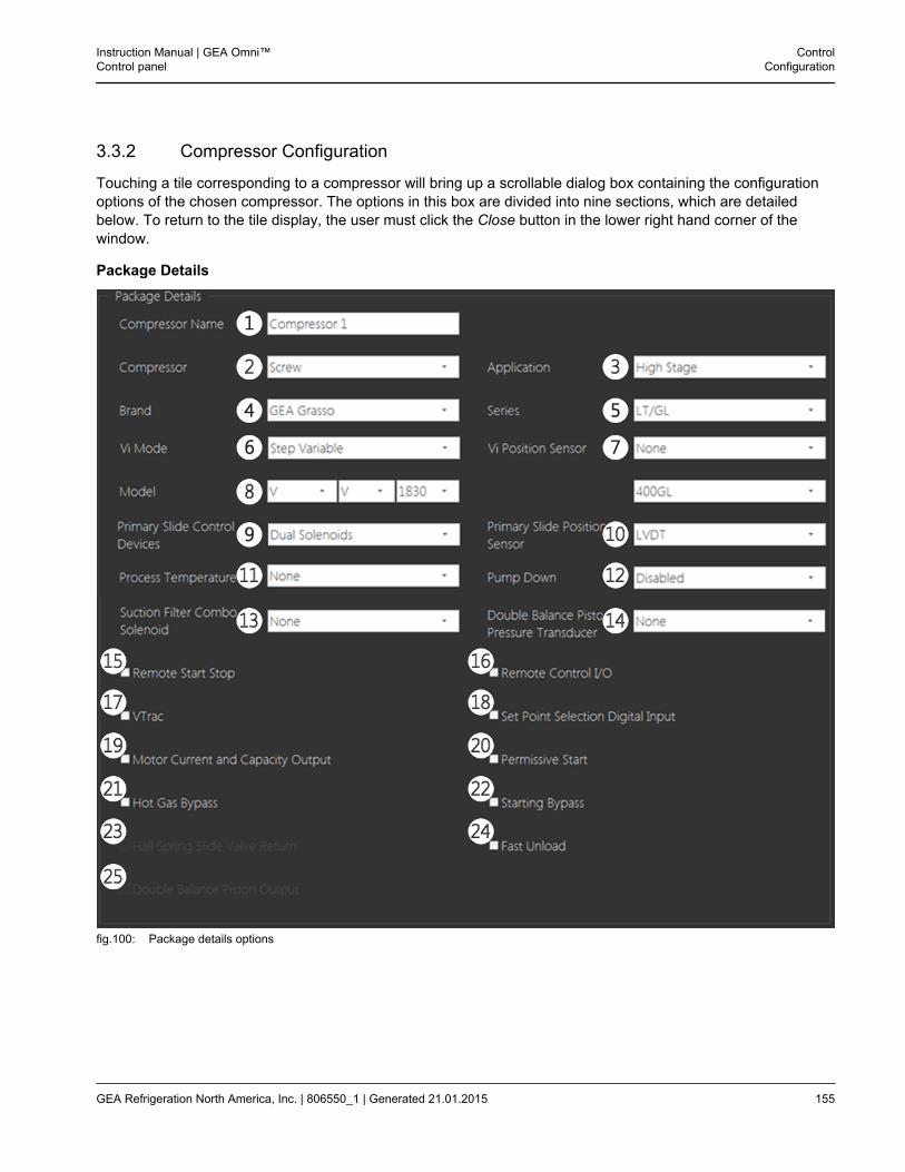
3.3.2 Compressor Configuration
Touching a tile corresponding to a compressor will bring up a scrollable dialog box containing the configurationoptions of the chosen compressor. The options in this box are divided into nine sections, which are detailedbelow. To return to the tile display, the user must click the Close button in the lower right hand corner of thewindow.
Package Details
fig.100: Package details options
Instruction Manual | GEA Omni™Control panel
ControlConfiguration
GEA Refrigeration North America, Inc. | 806550_1 | Generated 21.01.2015 155
1. Compressor NameThis text box is used as the name of the compressor. The name in this field will be displayed on the com-pressor tile on the main options screen.
2. CompressorThis drop down list is used to select the type of compressor the package contains. The options are:
• Screw
• Recip
• Centrifugal
3. ApplicationThis drop down list is used to select the function of the compressor. The options are:
• Standard / High Stage
• Booster / Low Stage
• Swing
• Heat Pump
4. BrandThis drop down list is used to select the compressor’s manufacturer information.
5. SeriesThis drop down list is used to select the series of the compressor. The options that will appear in this boxare dependent on the selected manufacturer.
6. Vi ModeThis drop down list is used to select the type of variable Vi control of the compressor. The options are:
• Fixed
• Continuous Variable
• Step Variable
7. Vi Position SensorThis drop down list is used to select the type of position sensor for monitoring the position of the VI, Vol-ume or Secondary Slide. If the compressor is fixed Vi, the only available option will be None. This optionmay not be modified in the field.
8. ModelThis drop down list is used to select the specific model number associated with the compressor. Theoptions that will appear in this box are dependent on the selected series and manufacturer.Furthermore, if the selected manufacturer is Grasso, the field will be split into three separate drop-downlists instead of one and a second drop down list will appear in the right column which. In this situation,changes in any drop down list will trigger a matching change in the other list.This option may only be modified in the field for certain compressor brands and series.
ControlConfiguration
Instruction Manual | GEA Omni™Control panel
156 GEA Refrigeration North America, Inc. | 806550_1 | Generated 21.01.2015
9. Primary Slide Control DevicesThis drop down list is used to select the type of device that will control the package’s primary capacityslide valve. This option may only be modified in the field for certain compressor brands and series. Theoptions are:
• Dual Solenoids
• Single Solenoids
10. Primary Slide Position SensorThis drop down list is used to select the type of sensor that monitors the current position of the capacityslide valve. The options are dependent on the brand and series of the compressor.
11. Process TemperatureThis drop down list is used to select where the compressor is equipped with process temperature sen-sors. The options are:
• None
• Inlet Temperature
• Outlet Temperature
• Both
12. Pump DownThis drop down list is used to select when the compressor will enter Pump Down mode. In Pump Downmode the compressor will be used to evacuate refrigerant from a chiller. The options are:
• Disabled
• Manual
• Auto
13. Suction Filter Combo SolenoidThis drop down list is used to enable control of the suction filter combo solenoid. Most GEA compressorswill use this control. The options are:
• None
• Normally Open
• Normally Closed
14. Double Balance Piston Pressure TransducerThis drop down list is used to select the range of the pressure transducer associated with the doublebalance piston.
15. Remote Start StopThis check box is used to select if the panel is equipped with an input to remotely start or stop the com-pressor.
Instruction Manual | GEA Omni™Control panel
ControlConfiguration
GEA Refrigeration North America, Inc. | 806550_1 | Generated 21.01.2015 157
16. Remote Control I/OThis check box is used to select if the panel is equipped with digital modules for remote control of thecompressor.
17. VTracThis check box is used to select whether the package is equipped with a VTrac Vibration monitor.
18. Set Point Selection Digital InputThis check box is used to select if the panel is equipped with a digital input to control the current controlset point remotely.
19. Motor Current and Capacity OutputThis check box is used to select if the panel is equipped with analog outputs to retransmit the compres-sor motor current and capacity.
20. Permissive StartThis check box is used to select if the panel is equipped with a digital input which must be energized toallow the compressor to start.
21. Hot Gas BypassThis check box is used to enable control of the Hot Gas Bypass solenoid, which is typically used to keepthe machine running under low load conditions.
22. Starting BypassThis check box is used to enable control of a suction to discharge bypass solenoid so as to reduce thetorque required to start the compressor.
23. Hall Spring Slide Valve ReturnThis check box is used to select if the compressor is equipped with a spring to force the slide valve backto zero if the compressor is stopped without unloading. This option is only enabled for Hall compressorretrofit applications.
24. Fast UnloadThis check box is used to enable control of the fast unload solenoid for retrofit applications.
25. Double Balance Piston OutputThis check box is used to enable control of a double balance piston solenoid. This option is only used forHE series compressors. This option may not be modified in the field.
ControlConfiguration
Instruction Manual | GEA Omni™Control panel
158 GEA Refrigeration North America, Inc. | 806550_1 | Generated 21.01.2015
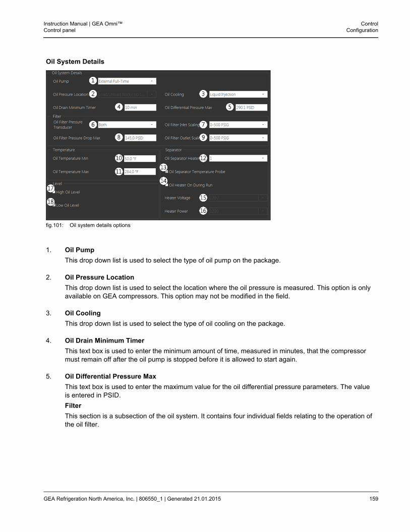
Oil System Details
fig.101: Oil system details options
1. Oil PumpThis drop down list is used to select the type of oil pump on the package.
2. Oil Pressure LocationThis drop down list is used to select the location where the oil pressure is measured. This option is onlyavailable on GEA compressors. This option may not be modified in the field.
3. Oil CoolingThis drop down list is used to select the type of oil cooling on the package.
4. Oil Drain Minimum TimerThis text box is used to enter the minimum amount of time, measured in minutes, that the compressormust remain off after the oil pump is stopped before it is allowed to start again.
5. Oil Differential Pressure MaxThis text box is used to enter the maximum value for the oil differential pressure parameters. The valueis entered in PSID.FilterThis section is a subsection of the oil system. It contains four individual fields relating to the operation ofthe oil filter.
Instruction Manual | GEA Omni™Control panel
ControlConfiguration
GEA Refrigeration North America, Inc. | 806550_1 | Generated 21.01.2015 159
6. Oil Filter Pressure TransducerThis drop down list is used to select whether the filter is equipped with pressure transducers and wherethey are located. The options are:
• None
• Inlet
• Outlet
• Both
7. Oil Filter Inlet ScalingThis drop down list is used to select the range of the pressure transducer at the oil filter inlet. This fieldwill be disabled if no inlet oil pressure transducer is present.
8. Oil Filter Pressure Drop MaxThis text box is used to enter the maximum value for the oil filter pressure parameters. The value isentered in PSID.
9. Oil Filter Outlet ScalingThis drop down list is used to select the range of the pressure transducer at the oil filter outlet. This fieldwill be disabled if no outlet oil pressure transducer is present.
TemperatureThis section is a subsection of the oil system. It contains two fields relating to temperature monitoring in the oilpump system.
10. Oil Temperature MinThis text box is used to set the minimum value which may be assigned to the oil temperature parame-ters. The value is measured in degrees Fahrenheit.
11. Oil Temperature MaxThis text box is used to set the maximum value which may be assigned to the oil temperature parame-ters. The value is measured in degrees Fahrenheit.
SeparatorThis section is a subsection of the oil system. It contains five fields relating to the operation of the oil separator.
12. Oil Separator HeatersThis drop down list is used to set the number of heaters that installed on the oil separator.
13. Oil Separator Temperature ProbeThis check box is used to select whether the oil separator is equipped with a dedicated temperature sen-sor or not.
ControlConfiguration
Instruction Manual | GEA Omni™Control panel
160 GEA Refrigeration North America, Inc. | 806550_1 | Generated 21.01.2015
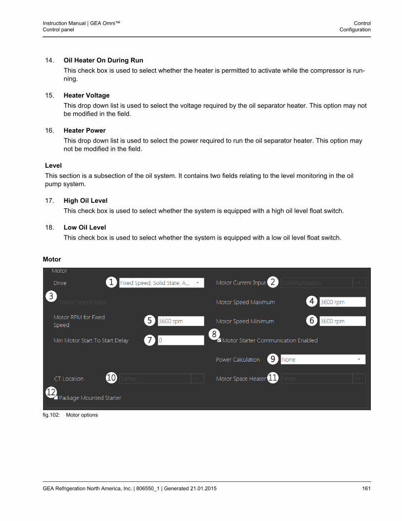
14. Oil Heater On During RunThis check box is used to select whether the heater is permitted to activate while the compressor is run-ning.
15. Heater VoltageThis drop down list is used to select the voltage required by the oil separator heater. This option may notbe modified in the field.
16. Heater PowerThis drop down list is used to select the power required to run the oil separator heater. This option maynot be modified in the field.
LevelThis section is a subsection of the oil system. It contains two fields relating to the level monitoring in the oilpump system.
17. High Oil LevelThis check box is used to select whether the system is equipped with a high oil level float switch.
18. Low Oil LevelThis check box is used to select whether the system is equipped with a low oil level float switch.
Motor
fig.102: Motor options
Instruction Manual | GEA Omni™Control panel
ControlConfiguration
GEA Refrigeration North America, Inc. | 806550_1 | Generated 21.01.2015 161
1. DriveThis drop down list is used to select the type of motor used in the package.
2. Motor Current InputThis drop down list is used to select the type of the current input for the motor
3. Motor Speed InputThis check box is used to select if the panel is equipped with an input to control motor spe
4. Motor Speed MaximumThis text box is used to enter the maximum allowable speed for the compressor motor. This option isonly used if the compressor is equipped with a variable speed motor. The value is entered in rpm.
5. Motor RPM for Fixed SpeedThis text box is used to enter the desired speed for the compressor motor. This option is only used if thecompressor is equipped with a fixed speed motor. The value is entered in rpm.
6. Motor Speed MinimumThis text box is used to enter the minimum allowable speed for the compressor motor. This option is onlyused if the compressor is equipped with a variable speed motor. The value is entered in rpm.
7. Min Motor Start To Start DelayThis text box is used to set the minimum amount of time after it has started, measured in minutes, thatthe motor must wait before starting again.
8. Motor Starter Communication EnabledThis check box is used to enable the direct control of a Benshaw motor starter using serial Modbus.
9. Power CalculationThis drop down list is used to select how the motor’s power is calculated. The options are:
• None
• Motor Current Input
• Direct Analog Input
10. CT LocationThis drop down list is used to select where on the package the current transformer is located. This optionmay not be modified in the field.
11. Motor Space HeaterThis is used to select the voltage required by the motor heater, if available. This option may not be modi-fied in the field.
12. Package Mounted StarterThis is used to select whether a motor starter is mounted on the package.
ControlConfiguration
Instruction Manual | GEA Omni™Control panel
162 GEA Refrigeration North America, Inc. | 806550_1 | Generated 21.01.2015
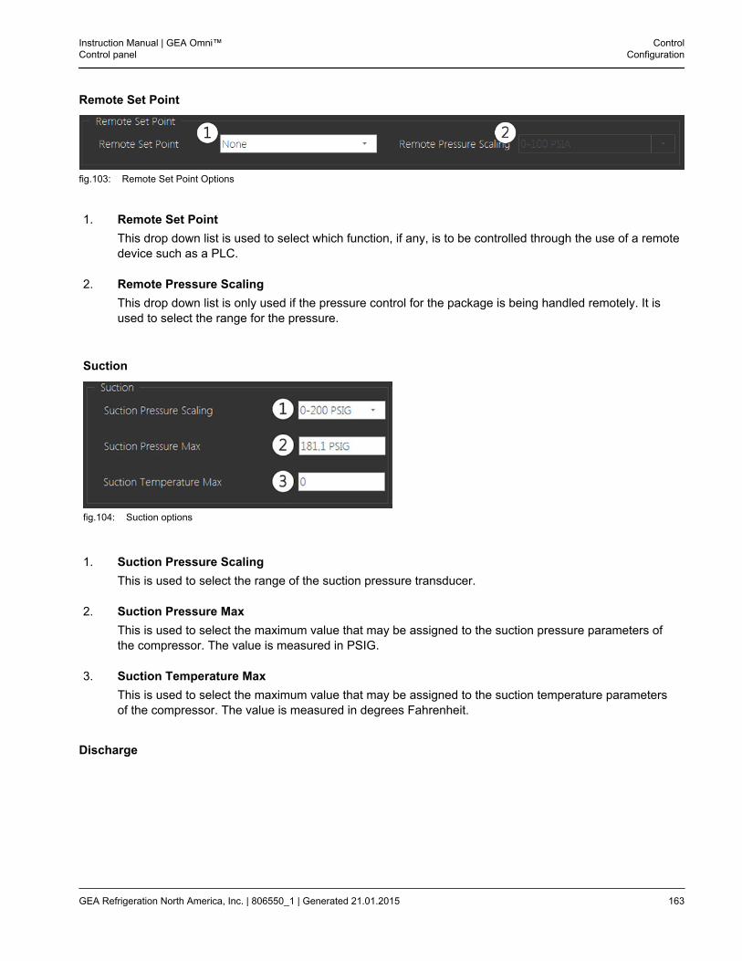
Remote Set Point
fig.103: Remote Set Point Options
1. Remote Set PointThis drop down list is used to select which function, if any, is to be controlled through the use of a remotedevice such as a PLC.
2. Remote Pressure ScalingThis drop down list is only used if the pressure control for the package is being handled remotely. It isused to select the range for the pressure.
Suction
fig.104: Suction options
1. Suction Pressure ScalingThis is used to select the range of the suction pressure transducer.
2. Suction Pressure MaxThis is used to select the maximum value that may be assigned to the suction pressure parameters ofthe compressor. The value is measured in PSIG.
3. Suction Temperature MaxThis is used to select the maximum value that may be assigned to the suction temperature parametersof the compressor. The value is measured in degrees Fahrenheit.
Discharge
Instruction Manual | GEA Omni™Control panel
ControlConfiguration
GEA Refrigeration North America, Inc. | 806550_1 | Generated 21.01.2015 163
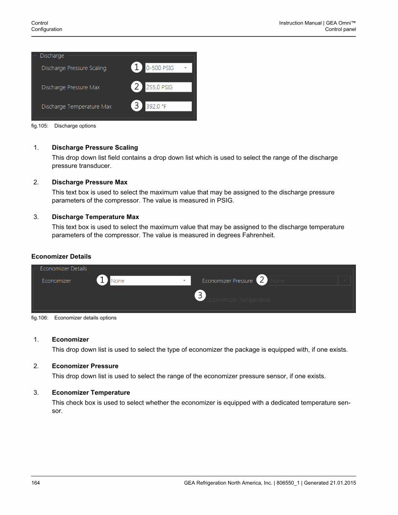
fig.105: Discharge options
1. Discharge Pressure ScalingThis drop down list field contains a drop down list which is used to select the range of the dischargepressure transducer.
2. Discharge Pressure MaxThis text box is used to select the maximum value that may be assigned to the discharge pressureparameters of the compressor. The value is measured in PSIG.
3. Discharge Temperature MaxThis text box is used to select the maximum value that may be assigned to the discharge temperatureparameters of the compressor. The value is measured in degrees Fahrenheit.
Economizer Details
fig.106: Economizer details options
1. EconomizerThis drop down list is used to select the type of economizer the package is equipped with, if one exists.
2. Economizer PressureThis drop down list is used to select the range of the economizer pressure sensor, if one exists.
3. Economizer TemperatureThis check box is used to select whether the economizer is equipped with a dedicated temperature sen-sor.
ControlConfiguration
Instruction Manual | GEA Omni™Control panel
164 GEA Refrigeration North America, Inc. | 806550_1 | Generated 21.01.2015
3.4 Normal Operating States
This section details the four normal compressor states which the compressor may be in while a shutdown condi-tion has not been annunciated.
3.4.1 Stopped Description
This mode of operation indicates that the compressor is not running and automatic start is disabled. While thepanel is in this mode, the red STOP button will be solidly illuminated.
3.4.2 Starting Description
This mode of operation indicates that the compressor is in the process of starting. During this period, the com-pressor will unload to its minimum position. The compressor will remain in this mode as long as the conditionsrequired for the compressor to start are not met and the compressor has not entered a shutdown condition.While the panel is in this mode, the START button will be blinking.The starting sequence follows the steps displayed below:
1. Check Oil Pump CirculationDuring this step, the panel will check that the oil temperature is greater than or equal to the value of the OilPump Circulation Temperature Set Point. If the oil temperature does not meet this condition, the oil pump willrun to attempt to bring the temperature reading up to the appropriate value. If the temperature has notreached the selected value after a period of time specified in the Oil Pump Circulation Shutdown Timerparameter, a shutdown will be annunciated. This step will only be displayed if the Oil Pump Circulation Modeparameter is set to Temperature.
2. Check Drive ConditionsDuring this step, the panel will check that the time periods specified in the Motor Start To Start Timer andMotor Stop To Start Timer parameters have elapsed.
3. Check Oil Drain TimerDuring this step, the panel will check whether the compressor must be drained of oil before being permittedto start. If the oil must be drained, the compressor will wait until the time period specified in the Oil DrainTimer parameter has elapsed.
4. Check Control Signal CyclingDuring this step, the panel will check the conditions of the compressor to ensure that the control value is in avalid state to start. This step will only be displayed if the Automatic Start Stop parameter is set to Enabled.
5. Check Permissive StartDuring this step, the panel will wait for the permissive start signal to become energized.
6. Check Pump Down Build To PressureDuring this step, the compressor will wait until the compressor suction pressure has risen to an acceptablevalue. This step will only be displayed if the Pump Down Mode is set to Automatic in the configuration.
7. Check Discharge Check ValveDuring this step, the panel will check to ensure that the motorized discharge check valve, if applicable, hasopened within an acceptable period of time.
Instruction Manual | GEA Omni™Control panel
ControlNormal Operating States
GEA Refrigeration North America, Inc. | 806550_1 | Generated 21.01.2015 165
8. Check Slide PositionDuring this step, the panel will ensure that the position of the capacity slide is below the value of theCapacity Slide Allowed To Start parameter.
9. Retrofit Oil Drain Input EnergizedDuring this step, the panel will wait for the compressor Oil Drain Input to become energized. This step willonly be displayed if the compressor Brand is set to a Hall with Internal/No Pump in the configuration.
10. Check Prelube TimerDuring this step, the oil pump will be run for a period of time specified in the Oil Pump Prelube Timer param-eter. This step will not be displayed if the compressor is set to a Grasso in the configuration.
11. Check Oil DifferentialDuring this step, the panel will check to ensure that the oil differential pressure is at an acceptable value.
12. Send Motor Start SignalDuring this step, the panel will energize the compressor motor starter output.
13. Check InterlockDuring this step, the panel will check to ensure that the motor starter interlock has become energized withinan appropriate amount of time and that the motor current reading is at an acceptable value.
3.4.3 Running Description
This mode of operation indicates that the compressor has successfully started. As long as it remains in thismode, the compressor will operate normally as dictated by the capacity control parameters. While in this mode,the green START button will be solidly illuminated.
3.4.4 Stopping Description
This mode of operation indicates that the compressor is in the process of stopping. During this period, the com-pressor will unload to its minimum position before stopping the compressor. While the panel is in this mode, theSTOP button will be blinking.The stopping sequence follows the steps displayed below:
1. Check Slide PositionDuring this step, the panel will ensure that the position of the capacity slide is below the value of theCapacity Slide Allowed To Start parameter.
2. Send Motor Stop SignalDuring this step, the panel will send the command to stop the compressor.
3. Check InterlockDuring this step, the panel will check to ensure that the motor starter interlock has become de-energizedwithin an appropriate amount of time and that the motor current reading is at an acceptable value.
3.5 Additional Operating States
This section details additional compressor states which may occur during operation.
• Illegally Started
ControlAdditional Operating States
Instruction Manual | GEA Omni™Control panel
166 GEA Refrigeration North America, Inc. | 806550_1 | Generated 21.01.2015
This state will occur if the compressor interlock is energized or motor current is received while the compres-sor should be stopped.
• ShutdownThis state will occur if a shutdown annunciation associated with the compressor in question is triggered. Formore information of specific shutdown annunciations, refer to Section 4.1, page 177.
• WarningThis state will occur if a warning annunciation associated with the compressor in question is triggered. Formore information of specific warning annunciations, refer to Section 4.2, page 182.
Instruction Manual | GEA Omni™Control panel
ControlAdditional Operating States
GEA Refrigeration North America, Inc. | 806550_1 | Generated 21.01.2015 167
3.6 Capacity Control
Movement of the compressor slide valve and the resulting change in capacity is done via a time-proportioningscheme.The Control Signal Parameter determines which variable the compressor uses to control capacity. The capacitycontrol parameters also allow the operator to select between multiple set points and set values for the associ-ated dead bands, and proportional bands.The capacity control algorithms determine the proper load or unload pulse width. The sum of the dead band andproportional band defines a range above and below the set point outside of which load and unload pulses will becontinuous. If the control signal falls within this range but remains outside the range above and below the setpoint defined by the dead band, then the duration of the capacity control pulses will begin to decrease. As longas the control signal remains within the range defined by the dead band, all capacity control pulses will stop.
3.6.1 Forward and Reverse
Capacity Control may be either forward or reverse acting, as described below. Which type of control is used isdependent on the application of the compressor. Typically, if the compressor is controlled on discharge pressureor slide valve position, the logic will be reversed. In all other applications, the logic will be forward acting.The graphs below display a visual representation of both types of capacity control.
ForwardForward acting capacity control manages the compressor control pulses via a time-proportioning scheme, asillustrated below.
ControlCapacity Control
Instruction Manual | GEA Omni™Control panel
168 GEA Refrigeration North America, Inc. | 806550_1 | Generated 21.01.2015
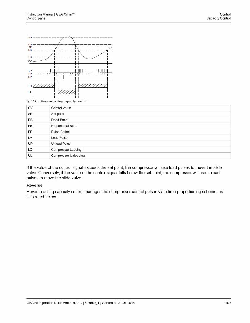
fig.107: Forward acting capacity control
CV Control Value
SP Set point
DB Dead Band
PB Proportional Band
PP Pulse Period
LP Load Pulse
UP Unload Pulse
LD Compressor Loading
UL Compressor Unloading
If the value of the control signal exceeds the set point, the compressor will use load pulses to move the slidevalve. Conversely, if the value of the control signal falls below the set point, the compressor will use unloadpulses to move the slide valve.
ReverseReverse acting capacity control manages the compressor control pulses via a time-proportioning scheme, asillustrated below.
Instruction Manual | GEA Omni™Control panel
ControlCapacity Control
GEA Refrigeration North America, Inc. | 806550_1 | Generated 21.01.2015 169
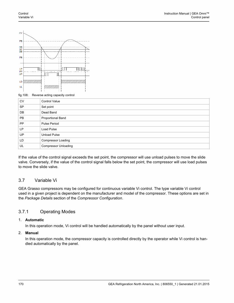
fig.108: Reverse acting capacity control
CV Control Value
SP Set point
DB Dead Band
PB Proportional Band
PP Pulse Period
LP Load Pulse
UP Unload Pulse
LD Compressor Loading
UL Compressor Unloading
If the value of the control signal exceeds the set point, the compressor will use unload pulses to move the slidevalve. Conversely, if the value of the control signal falls below the set point, the compressor will use load pulsesto move the slide valve.
3.7 Variable Vi
GEA Grasso compressors may be configured for continuous variable Vi control. The type variable Vi controlused in a given project is dependent on the manufacturer and model of the compressor. These options are set inthe Package Details section of the Compressor Configuration.
3.7.1 Operating Modes
1. AutomaticIn this operation mode, Vi control will be handled automatically by the panel without user input.
2. ManualIn this operation mode, the compressor capacity is controlled directly by the operator while Vi control is han-dled automatically by the panel.
ControlVariable Vi
Instruction Manual | GEA Omni™Control panel
170 GEA Refrigeration North America, Inc. | 806550_1 | Generated 21.01.2015
3.7.2 Types of Vi Control Systems
GEA Grasso Compressors use one of two different systems for combined Vi partial load control. All GEA Vi sys-tems utilize an optimum Vi slide position which is calculated based on the type of refrigerant in use, the operatingmode of the compressor and the current Capacity Slide Position using a proprietary formula.
1. Parallel Slide (PS) SystemThis type of control is used by compressors in the SH family (types C, D, E and G) and the MC family (typesH, L, M and N). It utilizes a pair of valves, the capacity slide and the Vi slide. These valves are placed inparallel with each other and may be adjusted independently. SH family compressors are equipped with a sin-gle position sensor which is used to monitor the capacity slide, while MC family compressors utilize a pair ofposition sensors to monitor both the capacity slide and the Vi slide.
2. Tandem Slide (TS) SystemThis type of control is used for compressors in the LT family (types P, R, S, T, V, W, Y, Z, XA, XB, XC, XD,XE and XF) and the new M family (types HM, LM, MM and NM). It utilizes a pair of slide valves, a primaryslide and a secondary slide, which are placed one in front of the other in the same cavity. To change theswept volume for the compressor, the primary slide will first load up to a maximum of the calculated optimumposition, after which the secondary slide will be varied to control the swept volume. Once the maximumswept volume is reached, both valves will move together to control the Vi. The compressor is equipped witha single position sensor on the primary slide. A second position sensor on the secondary slide is optional.
3. Vi Slide only with speed controlThis type of control is used for compressors in the MC family (types H, L, M and N) that have no parallelslide installed. It utilizes a pair of valves and the Vi slide which are placed on the compressor housingdirectly. These compressors are equipped with a single position sensor which is used to monitor the Vi slide.
Instruction Manual | GEA Omni™Control panel
ControlVariable Vi
GEA Refrigeration North America, Inc. | 806550_1 | Generated 21.01.2015 171
3.7.3 Combined Vi Partial Load Control
GEA Grasso compressors may be configured for continuous variable Vi control. The type variable Vi controlused in a given project is dependent on the manufacturer and model of the compressor. These options are set inthe Package Details section of the Compressor Configuration.
1. SH FamilyThe Vi control of the SH Family of compressors is accomplished using a series of two parallel slides that areoperated independently to maintain the desired Vi and capacity of the compressor.The capacity slide is used to adjust the capacity of the compressor to maintain the desired control value setpoint and is completely independent of the Vi slide.The Vi slide is used to maintain the optimum Vi for the current operating conditions. The Vi slide is loaded orunloaded based upon a calculated value that is a function of the current optimum Vi setting and high and lowVi limits of the compressor. This calculated optimum Vi is displayed on the compressor tile in the form X.XVi. If the optimum Vi for the compressor is below the midpoint of the Vi range, the Vi slide is loaded. Con-versely, if the optimum Vi is above the midpoint of the Vi range, the Vi slide is unloaded.The Vi slide isloaded or unload in this manner when the compressor is running. There is no positional feedback from the Vislide, subsequently, there is no value displayed value for the Vi slide valve on SH Family compressors.
2. MC FamilyThe Vi control of MC Family compressors is accomplished using a series of two parallel slides that are oper-ated simultaneously maintain the desired Vi and capacity of the compressor. Each slide operates independ-ently and has its own position indicator and proportional controller mechanism.The capacity slide is used to adjust the capacity of the compressor to maintain the desired control value setpoint and is completely independent of the Vi slide.The Vi Slide is used to maintain the optimum Vi for the current operating conditions. The optimum position ofthe Vi Slide is a calculated value that is a function of the current optimum Vi setting and the current primaryslide valve reading. The physical position of the Vi slide is displayed as Volume Slide Position, whichappears on the Operating Data table as a percent. The GEA Omni™ is programmed to proportionally load orunload the Volume slide as needed until its percentage falls within a range of the calculated optimum Vi per-centage defined by the Vi Deadband parameter, at which point the compresor is considered to be operatingat the optimum Vi Setting.
ControlVariable Vi
Instruction Manual | GEA Omni™Control panel
172 GEA Refrigeration North America, Inc. | 806550_1 | Generated 21.01.2015

3. LT FamilyThe Vi control LT Series compressors is accomplished using two slides that operate in tandem with oneanother to simultaneously maintain the desired Vi and capacity of the compressor. To achieve the desired Visetting, the primary slide is moved initially, with adjustments to the secondary slide being carried out after-ward to maintain the optimal Vi setting.There are three Vi Modes for LT Family compressors. The current mode the compressor is operating indetermines which slide will be moved to control capacity and which slide will be used to achieve the desiredVi setting. The calculated optimum Vi is displayed on the Compressor tile.
• Mode #1In this Vi mode, the primary slide is moved to control the capacity of the machine and the secondaryslide is kept unloaded. The secondary of the compressor in Mode #1 is therefore a function of the move-ment of the primary slide in order to maintain the desired suction pressure or process temperature set-point. The primary slide is used to control the capacity of the machine from completely unloaded up to aposition where the optimum Vi for the operating conditions is located. If the machine is attempting to loadand the primary slide reading exceeds the calculated primary slide position for the optimum Vi, the com-pressor will transtion from Mode #1 to Mode #2.
• Mode #2While in Mode #2, the primary slide will only be moved to correct for changes in the calculated primaryslide position. Adjustments in capacity will be handled by the secondary slide. The optimum Vi is con-stantly recalculated based on the current operating conditions. There is typically no positional feedbackfrom the Vi slide; subsequently, there is no value for the secondary slide valve position for LT Familycompressors.When the machine is attempting to load and has initially entered Mode #2 from Mode #1, a thirty secondload timer is started. Continous load signals will transition from Mode #2 to Mode #3 in thirty seconds.Short load pulses will take a proportionally longer time to transition because the timer is only permitted toadvance for the duration of each pulse. The primary slide reading will increase proportionally over thisthirty second period. With this method, the accumulating load signals are used to alter the displayedslide valve reading from the value of the optimum Vi position to 100%. The primary slide reading will beapproaching 100% at the same time as the equivalent of thirty seconds of loading elapse. When thetimer has accumulated the full thirty seconds, the Vi Mode will transition from Mode #2 to Mode #3, lock-ing the machine at 100%.An unload signal that interrupts the thirty second transition period from Mode #2 to Mode #3 will auto-matically set a new transition period for the compressor to move from Mode #2 back to Mode #1. Thistransition timer will be set to a period of time equal to the amount of time that the compressor had beenloading while in Mode #2. This method allows the panel to determine a relative position for the secon-dary slide based on the duration of load pulses. For example, if the compressor has accumulated twelveseconds of Load pulses in Mode #2 and begins unloading, twelve seconds of unload pulses must accu-mulate prior to returning to Mode #1.Similarly, if the machine is attempting to unload and has initially entered Mode #2 from Mode #3, a thirtysecond unload timer is started. If a request to unload the compressor continues for a total of thirty sec-onds, the Vi Mode will transition to Mode #1. A load signal that interrupts the thirty second Mode #2 toMode #1 transition timer will automatically set a new transition period for the compressor to move fromMode #2 back to Mode #3. This transition timer will be set to a period of time equal to the amount of timethat the compressor had been unloading while in Mode #2. This method allows the panel to determine arelative position for the secondary slide based on the duration of unload pulses. For example, if the com-pressor has accumulated 18 seconds of Unload pulses in Vi Mode #2 and begins loading, 18 seconds ofload pulses must accumulate prior to returning to Vi Mode #3.
Instruction Manual | GEA Omni™Control panel
ControlVariable Vi
GEA Refrigeration North America, Inc. | 806550_1 | Generated 21.01.2015 173
• Mode #3In this mode, the primary slide continues to track the value of the optimum Vi and the secondary slide isplaced in load to force the compressor to maximum capacity. This ensures the maximum capacity fromthe compressor while maintaining the optimum Vi setting for the current operating conditions. Thecapacity slide of the compressor will always be displayed as 100% while operating in Mode #3. While thecompressor is in this mode, any unload signal will cause the Vi Mode #3 to transition back to Mode #2.
ControlVariable Vi
Instruction Manual | GEA Omni™Control panel
174 GEA Refrigeration North America, Inc. | 806550_1 | Generated 21.01.2015
3.8 Lubrication System
3.8.1 Full Time
For this type of lubrication system, when the compressor is instructed to start, the oil pump will start and run forthe period of time defined by the Prelube Timer if applicable. During this prelube period, the oil pump mustdevelop adequate oil pressure so that the oil differential pressure falls within the range defined by the Low OilDifferential Pressure Shutdown and the High Oil Differential Shutdown parameters. In addition, if the capacityslide position is above the Maximum Capacity Slide Allow to Start parameter, the panel will attempt to unload thecompressor to a capacity slide position below this parameter. Both of these conditions must be satisfied prior tothe panel issuing a compressor start command. The oil pump will stop if the compressor fails to start, but willotherwise run continuously for as long as the compressor is in the running state. Once the compressor is stop-ped, either normally or due to a shutdown condition, the oil pump will continue to run until the capacity slide hasreturned to its minimum position. If the compressor was stopped normally, the oil pump will continue to run for aperiod of time defined by the Oil Pump Postlube Timer if applicable.
3.8.2 Full Time with No Prelube
For this type of lubrication system, when the compressor is instructed to start, the oil pump will start and run todevelop a minimum pressure differential. The pressure differential used in this type of system is not user adjusta-ble. Additionally, if the capacity slide position is higher than the value of the Maximum Capacity Slide to AllowStart parameter, the compressor will attempt to unload the capacity slide until the reading falls below the value ofthe parameter. Once both conditions have been met, the compressor will be permitted to issue a start command.The oil pump will stop if the compressor fails to start, but will otherwise run continuously for as long as the com-pressor is in the running state. Once the compressor is stopped, either normally or due to a shutdown condition,the oil pump will continue to run until the capacity slide has returned to its minimum position. If the compressorwas stopped normally, the oil pump will continue to run for a period of time defined by the Oil Pump PostlubeTimer if applicable.
3.8.3 Startup
For this type of lubrication system, when the compressor is instructed to start, the oil pump will start and run forthe period of time defined by the Prelube Timer, if applicable. During this prelube period, the oil pump mustdevelop adequate oil pressure so that the oil differential pressure falls within the range defined by the Low OilDifferential Pressure Shutdown and the High Oil Differential Shutdown parameters. In addition, if the capacityslide position is above the Maximum Capacity Slide to Allow Start parameter, the panel will attempt to unload thecompressor to a capacity slide position below this parameter. Both of these conditions must be satisfied prior tothe panel issuing a compressor start command. Once the compressor enters the running state, the oil pump willbe stopped.
3.8.4 No Pump
This option is selected if the compressor is not equipped with an external oil pump. In this situation, the oil pres-sure differential is maintained by the compressor.
Instruction Manual | GEA Omni™Control panel
ControlLubrication System
GEA Refrigeration North America, Inc. | 806550_1 | Generated 21.01.2015 175
3.9 IntelliSOC
An electronic modulating valve is provided to control the oil cooling. The position of the valve is based on thedischarge or oil temperature. The desired temperature is an operator-adjustable parameter. The modulatingvalve is held closed for two seconds after the shutoff solenoid is energized to allow pressure to build against thecontrol valve.The modulating valve will calibrate itself every time the compressor is successfully stopped from the runningstate. While calibrating, the valve will be set to 4mA and fully close to its 0% position. It will remain in this statefor a period of time as defined in the Calibrate Time Before Bleed parameter. Following the delay, the valve willremain at its minimum position until the compressor is started. At its minimum position, the valve is permitted toopen slightly to prevent liquid from becoming trapped between the valve and the shutoff solenoid.
ControlIntelliSOC
Instruction Manual | GEA Omni™Control panel
176 GEA Refrigeration North America, Inc. | 806550_1 | Generated 21.01.2015
4 ANNUNCIATIONS
4.1 Shutdowns
Shutdown annunciations are triggered when a condition occurs that requires the system to be disabled to protectone or more of its components. Once a shutdown is annunciated, the user may acknowledge it at any time. Anacknowledged shutdown will clear if the issue that triggered it is resolved, but a shutdown that has not beenacknowledged will persist until a user marks it as acknowledged.
List and Description of Shutdowns
Shutdown Explanation
Loss of Communications I/ONetwork
This annunciation will be triggered if the panel loses its connection to an I/OBus Coupler.
Watchdog IO Network This annunciation will be triggered if the panel is connected properly to anI/O Bus Coupler, but one or more of the connected slices are not functioningproperly.
High Motor Current Shutdown This annunciation will be triggered if the compressor motor current exceedsthe value entered in the High Motor Current Shutdown parameter for a periodof time defined in the High Motor Current Shutdown Timer parameter.
Sensor Failure Shutdown This annunciation will be triggered if the reading of a sensor is outside itsdefined range. This annunciation will only be triggered if the failed sensor iscritical to the safe operation of the compressor.
High Motor Speed Shutdown This annunciation will be triggered if the compressor motor speed exceedsthe value entered in the High Motor Speed Shutdown parameter.
Low Motor Speed Shutdown This annunciation will be triggered if the compressor motor speed falls belowthe value entered in the Low Motor Speed Shutdown’ parameter.
Low Motor Current Shutdown This annunciation will be triggered if the compressor motor current fallsbelow the value entered in the Low Motor Current Shutdown parameter for aperiod of time defined in the Low Motor Current Shutdown Timer parameter.
Capacity Slide Failed ToUnload
This annunciation will be triggered if, either before starting or after stopping,the compressor has not unloaded to its minimum position for a time period inexcess of the value selected in the Capacity Slide Failed To Unload Shut-down Timer parameter.
Low Suction Pressure Shut-down
This annunciation will be triggered if the suction pressure reading of the com-pressor drops below the value entered in the Low Suction Pressure Shut-down parameter.
Instruction Manual | GEA Omni™Control panel
AnnunciationsShutdowns
GEA Refrigeration North America, Inc. | 806550_1 | Generated 21.01.2015 177
List and Description of Shutdowns
Shutdown Explanation
High Discharge TemperatureShutdown
This annunciation will be triggered if the discharge temperature reading ofthe compressor exceeds the value entered in the High Discharge Tempera-ture Shutdown parameter.
High Discharge Pressure Shut-down
This annunciation will be triggered if the discharge pressure reading of thecompressor exceeds the value entered in the High Discharge Pressure Shut-down parameter.
High Oil Separator Tempera-ture Shutdown
This annunciation will be triggered if the oil separator temperature readingexceeds the value of the High Oil Separator Temperature Shutdown parame-ter. This shutdown will only be annunciated if the compressor is in the start-ing or running states.
Low Oil Separator TemperatureShutdown
This annunciation will be triggered if the oil separator temperature readingfalls below the value of the Low Oil Separator Temperature Shutdownparameter. This shutdown will only be annunciated if the compressor is in thestarting or running states.
Low Oil Level Shutdown This annunciation will be triggered if the Low Oil Level Input becomes de-energized for a period of time in excess of the value entered in the Low OilLevel Shutdown Timer.
High Oil Temperature Shut-down
This annunciation will be triggered if the oil temperature reading exceeds thevalue of the High Oil Temperature Shutdown parameter. This shutdown willonly be annunciated if the compressor is in the starting or running states.
Low Oil Temperature Shutdown This annunciation will be triggered if the oil temperature reading falls belowthe value of the Low Oil Temperature Shutdown parameter. This shutdownwill only be annunciated if the compressor is in the starting or running states.
High Oil Differential PressureShutdown
This annunciation will be triggered if the oil differential pressure readingexceeds the value of the High Oil Differential Pressure Shutdown parameter.This shutdown will only be annunciated if the compressor is in the starting orrunning states.
Low Oil Differential PressureShutdown
This annunciation will be triggered if the oil differential pressure reading fallsbelow the value of the Low Oil Differential Pressure Shutdown parameter.This shutdown will only be annunciated if the compressor is in the starting orrunning states.
High Oil Filter Differential Shut-down
This annunciation will be triggered if the oil filter differential pressure readingexceeds the value of the High Oil Filter Differential Pressure Shutdownparameter. This shutdown will only be annunciated if the compressor is in thestarting or running states.
AnnunciationsShutdowns
Instruction Manual | GEA Omni™Control panel
178 GEA Refrigeration North America, Inc. | 806550_1 | Generated 21.01.2015
List and Description of Shutdowns
Shutdown Explanation
Oil Pump Illegal Interlock Shut-down
This annunciation will be triggered if the oil pump interlock input becomesenergized while the oil pump start output is de-energized..
Oil Pump 1 Illegal InterlockShutdown
This annunciation will be triggered if the interlock input of the lead oil pump ina dual pump system becomes energized while the lead pump start output isde-energized. This annunciation will only be enabled if the compressor isconfigured with dual oil pumps.
Oil Pump 2 Illegal InterlockShutdown
This annunciation will be triggered if the interlock input of the lag oil pump ina dual pump system becomes energized while the lag pump start output isde-energized. This annunciation will only be enabled if the compressor isconfigured with dual oil pumps.
Oil Pump Loss of InterlockShutdown
This annunciation will be triggered if the oil pump interlock input becomes de-energized while the oil pump start output is energized.
High Oil Separator Level Shut-down
This annunciation will be triggered if the level in the oil separator remainsabove the high level float switch for a period of time greater than the High OilSeparator Shutdown Timer parameter.
Compressor Illegal InterlockShutdown
This annunciation will be triggered if the compressor run status inputbecomes energized while the compressor start output is de-energized.
Illegal Compressor Motor Cur-rent Shutdown
This annunciation will be triggered if the motor current of the compressor ishigher than the percentage of the motor FLA as indicated by the value of theIllegal Compressor Motor Current Shutdown while compressor should bestopped.
Compressor Loss of Compres-sor Interlock
This annunciation will be triggered if the compressor run status inputbecomes de-energized while the compressor start output is energized.
Analog Input Count MismatchShutdown
This annunciation will be triggered if the number of Analog Input slicesdetected by the panel is different from the number called for in the configura-tion.
Analog Output Count MismatchShutdown
This annunciation will be triggered if the number of Analog Output slicesdetected by the panel is different from the number called for in the configura-tion.
Digital Input Count MismatchShutdown
This annunciation will be triggered if the number of Digital Input slicesdetected by the panel is different from the number called for in the configura-tion.
Instruction Manual | GEA Omni™Control panel
AnnunciationsShutdowns
GEA Refrigeration North America, Inc. | 806550_1 | Generated 21.01.2015 179
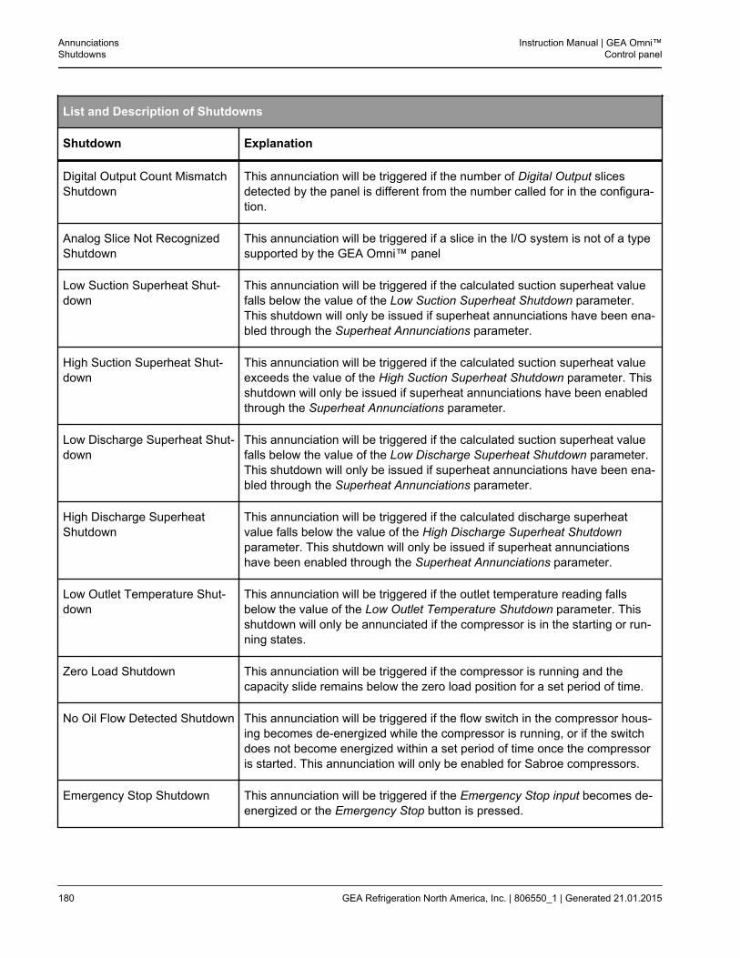
List and Description of Shutdowns
Shutdown Explanation
Digital Output Count MismatchShutdown
This annunciation will be triggered if the number of Digital Output slicesdetected by the panel is different from the number called for in the configura-tion.
Analog Slice Not RecognizedShutdown
This annunciation will be triggered if a slice in the I/O system is not of a typesupported by the GEA Omni™ panel
Low Suction Superheat Shut-down
This annunciation will be triggered if the calculated suction superheat valuefalls below the value of the Low Suction Superheat Shutdown parameter.This shutdown will only be issued if superheat annunciations have been ena-bled through the Superheat Annunciations parameter.
High Suction Superheat Shut-down
This annunciation will be triggered if the calculated suction superheat valueexceeds the value of the High Suction Superheat Shutdown parameter. Thisshutdown will only be issued if superheat annunciations have been enabledthrough the Superheat Annunciations parameter.
Low Discharge Superheat Shut-down
This annunciation will be triggered if the calculated suction superheat valuefalls below the value of the Low Discharge Superheat Shutdown parameter.This shutdown will only be issued if superheat annunciations have been ena-bled through the Superheat Annunciations parameter.
High Discharge SuperheatShutdown
This annunciation will be triggered if the calculated discharge superheatvalue falls below the value of the High Discharge Superheat Shutdownparameter. This shutdown will only be issued if superheat annunciationshave been enabled through the Superheat Annunciations parameter.
Low Outlet Temperature Shut-down
This annunciation will be triggered if the outlet temperature reading fallsbelow the value of the Low Outlet Temperature Shutdown parameter. Thisshutdown will only be annunciated if the compressor is in the starting or run-ning states.
Zero Load Shutdown This annunciation will be triggered if the compressor is running and thecapacity slide remains below the zero load position for a set period of time.
No Oil Flow Detected Shutdown This annunciation will be triggered if the flow switch in the compressor hous-ing becomes de-energized while the compressor is running, or if the switchdoes not become energized within a set period of time once the compressoris started. This annunciation will only be enabled for Sabroe compressors.
Emergency Stop Shutdown This annunciation will be triggered if the Emergency Stop input becomes de-energized or the Emergency Stop button is pressed.
AnnunciationsShutdowns
Instruction Manual | GEA Omni™Control panel
180 GEA Refrigeration North America, Inc. | 806550_1 | Generated 21.01.2015
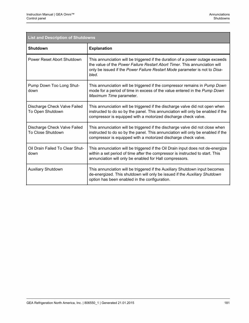
List and Description of Shutdowns
Shutdown Explanation
Power Reset Abort Shutdown This annunciation will be triggered if the duration of a power outage exceedsthe value of the Power Failure Restart Abort Timer. This annunciation willonly be issued if the Power Failure Restart Mode parameter is not to Disa-bled.
Pump Down Too Long Shut-down
This annunciation will be triggered if the compressor remains in Pump Downmode for a period of time in excess of the value entered in the Pump DownMaximum Time parameter.
Discharge Check Valve FailedTo Open Shutdown
This annunciation will be triggered if the discharge valve did not open wheninstructed to do so by the panel. This annunciation will only be enabled if thecompressor is equipped with a motorized discharge check valve.
Discharge Check Valve FailedTo Close Shutdown
This annunciation will be triggered if the discharge valve did not close wheninstructed to do so by the panel. This annunciation will only be enabled if thecompressor is equipped with a motorized discharge check valve.
Oil Drain Failed To Clear Shut-down
This annunciation will be triggered if the Oil Drain input does not de-energizewithin a set period of time after the compressor is instructed to start. Thisannunciation will only be enabled for Hall compressors.
Auxiliary Shutdown This annunciation will be triggered if the Auxiliary Shutdown input becomesde-energized. This shutdown will only be issued if the Auxiliary Shutdownoption has been enabled in the configuration.
Instruction Manual | GEA Omni™Control panel
AnnunciationsShutdowns
GEA Refrigeration North America, Inc. | 806550_1 | Generated 21.01.2015 181
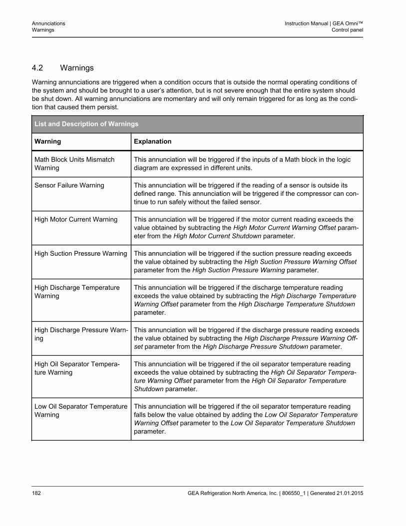
4.2 Warnings
Warning annunciations are triggered when a condition occurs that is outside the normal operating conditions ofthe system and should be brought to a user’s attention, but is not severe enough that the entire system shouldbe shut down. All warning annunciations are momentary and will only remain triggered for as long as the condi-tion that caused them persist.
List and Description of Warnings
Warning Explanation
Math Block Units MismatchWarning
This annunciation will be triggered if the inputs of a Math block in the logicdiagram are expressed in different units.
Sensor Failure Warning This annunciation will be triggered if the reading of a sensor is outside itsdefined range. This annunciation will be triggered if the compressor can con-tinue to run safely without the failed sensor.
High Motor Current Warning This annunciation will be triggered if the motor current reading exceeds thevalue obtained by subtracting the High Motor Current Warning Offset param-eter from the High Motor Current Shutdown parameter.
High Suction Pressure Warning This annunciation will be triggered if the suction pressure reading exceedsthe value obtained by subtracting the High Suction Pressure Warning Offsetparameter from the High Suction Pressure Warning parameter.
High Discharge TemperatureWarning
This annunciation will be triggered if the discharge temperature readingexceeds the value obtained by subtracting the High Discharge TemperatureWarning Offset parameter from the High Discharge Temperature Shutdownparameter.
High Discharge Pressure Warn-ing
This annunciation will be triggered if the discharge pressure reading exceedsthe value obtained by subtracting the High Discharge Pressure Warning Off-set parameter from the High Discharge Pressure Shutdown parameter.
High Oil Separator Tempera-ture Warning
This annunciation will be triggered if the oil separator temperature readingexceeds the value obtained by subtracting the High Oil Separator Tempera-ture Warning Offset parameter from the High Oil Separator TemperatureShutdown parameter.
Low Oil Separator TemperatureWarning
This annunciation will be triggered if the oil separator temperature readingfalls below the value obtained by adding the Low Oil Separator TemperatureWarning Offset parameter to the Low Oil Separator Temperature Shutdownparameter.
AnnunciationsWarnings
Instruction Manual | GEA Omni™Control panel
182 GEA Refrigeration North America, Inc. | 806550_1 | Generated 21.01.2015
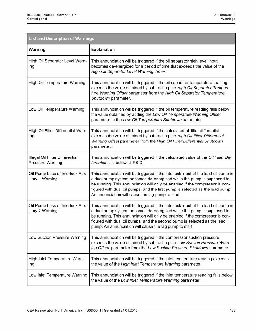
List and Description of Warnings
Warning Explanation
High Oil Separator Level Warn-ing
This annunciation will be triggered if the oil separator high level inputbecomes de-energized for a period of time that exceeds the value of theHigh Oil Separator Level Warning Timer.
High Oil Temperature Warning This annunciation will be triggered if the oil separator temperature readingexceeds the value obtained by subtracting the High Oil Separator Tempera-ture Warning Offset parameter from the High Oil Separator TemperatureShutdown parameter.
Low Oil Temperature Warning This annunciation will be triggered if the oil temperature reading falls belowthe value obtained by adding the Low Oil Temperature Warning Offsetparameter to the Low Oil Temperature Shutdown parameter.
High Oil Filter Differential Warn-ing
This annunciation will be triggered if the calculated oil filter differentialexceeds the value obtained by subtracting the High Oil Filter DifferentialWarning Offset parameter from the High Oil Filter Differential Shutdownparameter.
Illegal Oil Filter DifferentialPressure Warning
This annunciation will be triggered if the calculated value of the Oil Filter Dif-ferential falls below -2 PSID.
Oil Pump Loss of Interlock Aux-iliary 1 Warning
This annunciation will be triggered if the interlock input of the lead oil pump ina dual pump system becomes de-energized while the pump is supposed tobe running. This annunciation will only be enabled if the compressor is con-figured with dual oil pumps, and the first pump is selected as the lead pump.An annunciation will cause the lag pump to start.
Oil Pump Loss of Interlock Aux-iliary 2 Warning
This annunciation will be triggered if the interlock input of the lead oil pump ina dual pump system becomes de-energized while the pump is supposed tobe running. This annunciation will only be enabled if the compressor is con-figured with dual oil pumps, and the second pump is selected as the leadpump. An annunciation will cause the lag pump to start.
Low Suction Pressure Warning This annunciation will be triggered if the compressor suction pressureexceeds the value obtained by subtracting the Low Suction Pressure Warn-ing Offset’ parameter from the Low Suction Pressure Shutdown parameter.
High Inlet Temperature Warn-ing
This annunciation will be triggered if the inlet temperature reading exceedsthe value of the High Inlet Temperature Warning parameter.
Low Inlet Temperature Warning This annunciation will be triggered if the inlet temperature reading falls belowthe value of the Low Inlet Temperature Warning parameter.
Instruction Manual | GEA Omni™Control panel
AnnunciationsWarnings
GEA Refrigeration North America, Inc. | 806550_1 | Generated 21.01.2015 183
List and Description of Warnings
Warning Explanation
High Outlet Temperature Warn-ing
This annunciation will be triggered if the outlet temperature reading exceedsthe value of the High Outlet Temperature Warning parameter.
Low Outlet Temperature Warn-ing
This annunciation will be triggered if the outlet temperature reading fallsbelow the value of the Low Outlet Temperature Warning parameter.
High Oil Differential PressureWarning
This annunciation will be triggered if the calculated oil differential pressureexceeds the value obtained by subtracting the High Oil Differential PressureWarning Offset parameter from the High Oil Differential Pressure Shutdownparameter.
Low Oil Differential PressureWarning
This annunciation will be triggered if the calculated oil differential pressurefalls below the value obtained by adding the Low Oil Differential PressureWarning Offset parameter to the Low Oil Differential Pressure Shutdownparameter.
Low Oil Differential PressureRunning Dual Pump Warning
This annunciation will be triggered if the calculated oil differential pressurefalls below the value obtained by adding the Low Oil Differential PressureWarning Offset parameter to the Low Oil Differential Pressure Shutdownparameter. This annunciation will only be triggered if the compressor is con-figured with dual oil pumps and the compressor is in the running state. Anannunciation will cause the lag pump to start.
Low Oil Differential PressureStarting Dual Pump Warning
This annunciation will be triggered if the calculated oil differential pressurefalls below the value obtained by adding the Low Oil Differential PressureWarning Offset’ parameter to the Low Oil Differential Pressure Shutdownparameter. This annunciation will only be triggered if the compressor is con-figured with dual oil pumps and the compressor is starting. An annunciationwill cause the lag pump to start.
Lost Communication WithSequencer
This annunciation will be triggered if the panel loses its connection to thesequencer after a valid connection has been established.
Loss Of Remote Start Signal This annunciation will be triggered if the compressor is unable to find a validremote start signal when it is switched to remote mode after being manuallystarted.
Auxiliary Warning This annunciation will be triggered if the auxiliary warning input becomes de-energized. This warning will only be issued if the Auxiliary Warning optionhas been enabled in the configuration.
AnnunciationsWarnings
Instruction Manual | GEA Omni™Control panel
184 GEA Refrigeration North America, Inc. | 806550_1 | Generated 21.01.2015
4.3 Notifications
List and Description of Notifications
Notifications Explanation
Need Updated Drawings This annunciation will be triggered if any change is made to the panel or con-figuration that will necessitate a change to the electrical drawings.
Upcoming Service RequiredNotification
This annunciation will be triggered if the panel is scheduled for maintenancewithin one hundred hours, as entered on the Maintenance chart in the Serv-ice screen. This annunciation will only trigger if the compressor has beenrunning for at least five hundred hours. This notification will not be annunci-ated if service notifications have been disabled.
Past Due Service RequiredNotification
This annunciation will be triggered if the current service interval has not beenmarked as complete and one hundred hours have passed since the intervalin question came due. If this notification is cleared, the panel will wait for thecompressor to run for another one hundred hours and, if the service intervalstill has not been completed, will annunciate the notification again. The notifi-cation will continue to be annunciated in one hundred hour increments untilthe service interval is marked as completed. This notification will not beannunciated if service notifications have been disabled.
Service Required Notification This annunciation will be triggered once the runtime of the panel has reachedthe next required service interval, as entered on the Maintenance chart in theService screen. This notification will not be annunciated if service notifica-tions have been disabled.
Instruction Manual | GEA Omni™Control panel
AnnunciationsNotifications
GEA Refrigeration North America, Inc. | 806550_1 | Generated 21.01.2015 185
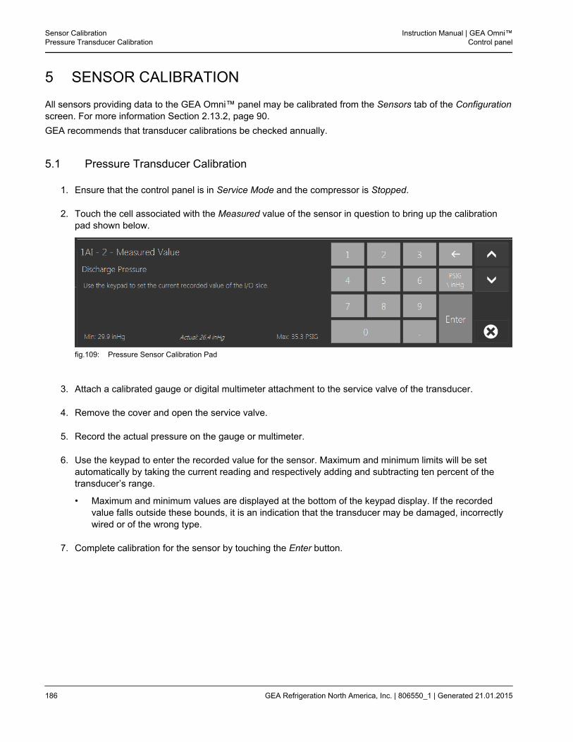
5 SENSOR CALIBRATION
All sensors providing data to the GEA Omni™ panel may be calibrated from the Sensors tab of the Configurationscreen. For more information Section 2.13.2, page 90.GEA recommends that transducer calibrations be checked annually.
5.1 Pressure Transducer Calibration
1. Ensure that the control panel is in Service Mode and the compressor is Stopped.
2. Touch the cell associated with the Measured value of the sensor in question to bring up the calibrationpad shown below.
fig.109: Pressure Sensor Calibration Pad
3. Attach a calibrated gauge or digital multimeter attachment to the service valve of the transducer.
4. Remove the cover and open the service valve.
5. Record the actual pressure on the gauge or multimeter.
6. Use the keypad to enter the recorded value for the sensor. Maximum and minimum limits will be setautomatically by taking the current reading and respectively adding and subtracting ten percent of thetransducer’s range.
• Maximum and minimum values are displayed at the bottom of the keypad display. If the recordedvalue falls outside these bounds, it is an indication that the transducer may be damaged, incorrectlywired or of the wrong type.
7. Complete calibration for the sensor by touching the Enter button.
Sensor CalibrationPressure Transducer Calibration
Instruction Manual | GEA Omni™Control panel
186 GEA Refrigeration North America, Inc. | 806550_1 | Generated 21.01.2015
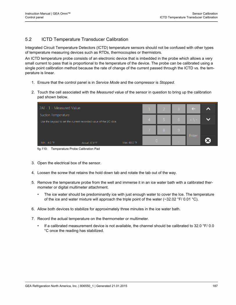
5.2 ICTD Temperature Transducer Calibration
Integrated Circuit Temperature Detectors (ICTD) temperature sensors should not be confused with other typesof temperature measuring devices such as RTDs, thermocouples or thermistors.An ICTD temperature probe consists of an electronic device that is imbedded in the probe which allows a verysmall current to pass that is proportional to the temperature of the device. The probe can be calibrated using asingle point calibration method because the rate of change of the current passed through the ICTD vs. the tem-perature is linear.
1. Ensure that the control panel is in Service Mode and the compressor is Stopped.
2. Touch the cell associated with the Measured value of the sensor in question to bring up the calibrationpad shown below.
fig.110: Temperature Probe Calibration Pad
3. Open the electrical box of the sensor.
4. Loosen the screw that retains the hold down tab and rotate the tab out of the way.
5. Remove the temperature probe from the well and immerse it in an ice water bath with a calibrated ther-mometer or digital multimeter attachment.
• The ice water should be predominantly ice with just enough water to cover the Ice. The temperatureof the ice and water mixture will approach the triple point of the water (~32.02 °F/ 0.01 °C).
6. Allow both devices to stabilize for approximately three minutes in the ice water bath.
7. Record the actual temperature on the thermometer or multimeter.
• If a calibrated measurement device is not available, the channel should be calibrated to 32.0 °F/ 0.0°C once the reading has stabilized.
Instruction Manual | GEA Omni™Control panel
Sensor CalibrationICTD Temperature Transducer Calibration
GEA Refrigeration North America, Inc. | 806550_1 | Generated 21.01.2015 187
8. Use the keypad to enter the recorded value for the sensor. Maximum and minimum limits will be setautomatically by taking the current reading and respectively adding and subtracting ten percent of thesensor´s range.
• Maximum and minimum values are displayed at the bottom of the keypad display. If the recordedvalue falls outside these bounds, it is an indication that the transducer may be damaged, incorrectlywired or of the wrong type.
9. Complete calibration for the sensor by touching the Enter button.
Sensor CalibrationICTD Temperature Transducer Calibration
Instruction Manual | GEA Omni™Control panel
188 GEA Refrigeration North America, Inc. | 806550_1 | Generated 21.01.2015
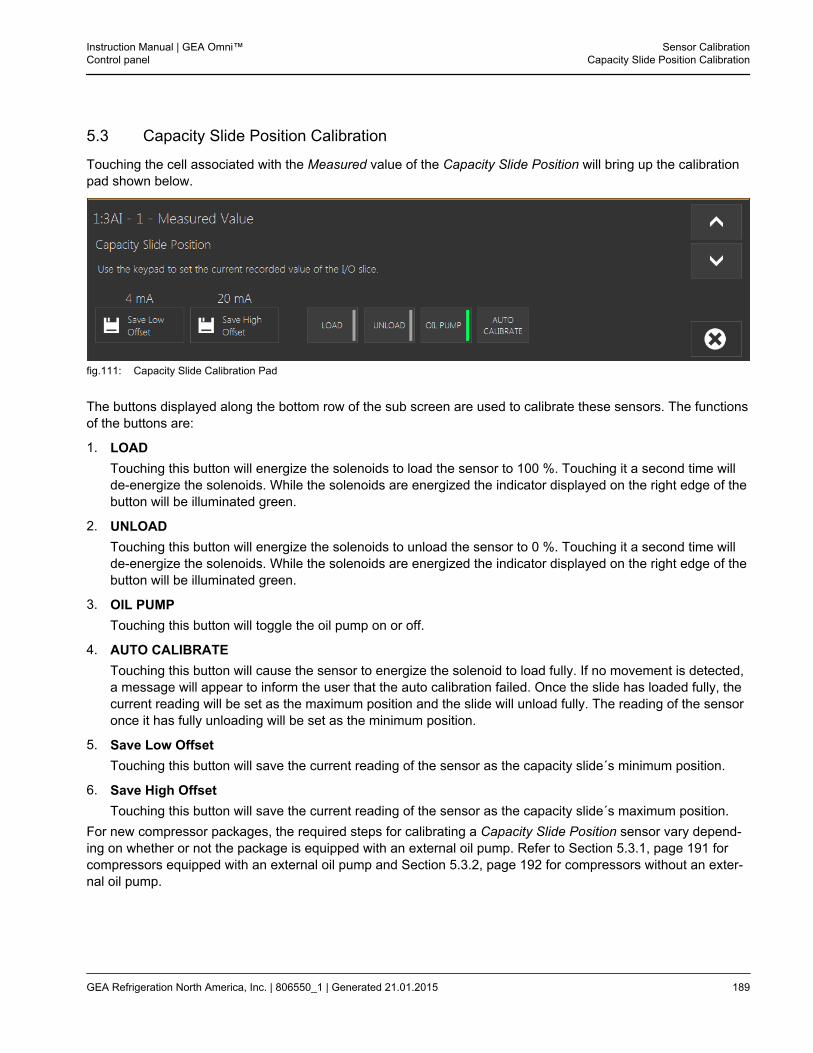
5.3 Capacity Slide Position Calibration
Touching the cell associated with the Measured value of the Capacity Slide Position will bring up the calibrationpad shown below.
fig.111: Capacity Slide Calibration Pad
The buttons displayed along the bottom row of the sub screen are used to calibrate these sensors. The functionsof the buttons are:
1. LOADTouching this button will energize the solenoids to load the sensor to 100 %. Touching it a second time willde-energize the solenoids. While the solenoids are energized the indicator displayed on the right edge of thebutton will be illuminated green.
2. UNLOADTouching this button will energize the solenoids to unload the sensor to 0 %. Touching it a second time willde-energize the solenoids. While the solenoids are energized the indicator displayed on the right edge of thebutton will be illuminated green.
3. OIL PUMPTouching this button will toggle the oil pump on or off.
4. AUTO CALIBRATETouching this button will cause the sensor to energize the solenoid to load fully. If no movement is detected,a message will appear to inform the user that the auto calibration failed. Once the slide has loaded fully, thecurrent reading will be set as the maximum position and the slide will unload fully. The reading of the sensoronce it has fully unloading will be set as the minimum position.
5. Save Low OffsetTouching this button will save the current reading of the sensor as the capacity slide´s minimum position.
6. Save High OffsetTouching this button will save the current reading of the sensor as the capacity slide´s maximum position.
For new compressor packages, the required steps for calibrating a Capacity Slide Position sensor vary depend-ing on whether or not the package is equipped with an external oil pump. Refer to Section 5.3.1, page 191 forcompressors equipped with an external oil pump and Section 5.3.2, page 192 for compressors without an exter-nal oil pump.
Instruction Manual | GEA Omni™Control panel
Sensor CalibrationCapacity Slide Position Calibration
GEA Refrigeration North America, Inc. | 806550_1 | Generated 21.01.2015 189
Hint!
Step variable Vi compressors manufactured by Mycom, Frick or Kobe will require a differentprocedure, which is detailed in Section 5.3.3, page 193.
Sensor CalibrationCapacity Slide Position Calibration
Instruction Manual | GEA Omni™Control panel
190 GEA Refrigeration North America, Inc. | 806550_1 | Generated 21.01.2015
5.3.1 Compressor Capacity Slide Input Calibration with External Oil Pump
1. Ensure that the control panel is in Service Mode and the compressor is Stopped.
2. Touch the Capacity Slide Position entry in the Sensor Calibration display to bring up the calibration pad.
3. Touch the OIL PUMP button. The indicator on the right edge of the button will be illuminated green toindicate that the oil pump is running. This step may be skipped for Vilter compressors.
4. Touch the UNLOAD button. Wait until the slide valve reaches the fully unloaded position, at which pointthe value in the Raw Signal column should stabilize. The value that the signal will stabilize to is deter-mined by the type of sensor being used.
Hint!
Certain Compressors will use reverse acting capacity sensors, which will stabilize to ahigh value at the low offset.
5. Touch the Save Low Offset button. The corresponding slide valve position sensor output has beenrecorded as the fully unloaded position.
6. Touch the LOAD button. Wait until the slide valve reaches the fully loaded position, at which point thevalue in the Raw Signal column should stabilize. The value that the signal will stabilize to is determinedby the type of sensor being used.
7. Touch the Save High Offset button, the corresponding slide valve position sensor output has beenrecorded as the fully loaded position.
8. Touch the UNLOAD button again. The compressor should fully unload and the indicated Capacity SlidePosition should track with it. Touch the LOAD button to fully load the compressor and observe theCapacity Slide Position.
9. If the Capacity Slide Position appears to track the Raw Signal, the calibration is complete. Turn off the oilpump by touching the OIL PUMP button a second time.
10. Otherwise, repeat the procedure from step #1. Ensure that the slide position indicator reading changessmoothly between full unload and full load.
11. Exit the calibration pad by touching the X button.
12. The compressor must remain stopped for a period of time determined by the Oil Drain Timer.
Instruction Manual | GEA Omni™Control panel
Sensor CalibrationCapacity Slide Position Calibration
GEA Refrigeration North America, Inc. | 806550_1 | Generated 21.01.2015 191
5.3.2 Compressor Capacity Slide Input Calibration without External Oil Pump
1. Ensure that the control panel is in Service Mode and the compressor is Stopped.
2. Touch the Capacity Slide Position entry in the Sensor Calibration display to bring up the calibration pad.
3. Verify that the compressor is physically fully unloaded. The GEA Omni™ will allow the compressor tostart if it has a slide valve reading less than 70 %. Otherwise, the slide valve mechanism must bemechanically adjusted to less than 70 % to allow the compressor to be initially started.
4. Start the compressor and wait until the compressor is Running and oil pressure has been established.
5 Touch the UNLOAD button. Wait until the slide valve reaches the fully unloaded position, at which pointthe value in the Raw Signal column should stabilize. The value that the signal will stabilize to is deter-mined by the type of sensor being used.
6. Touch the Save Low Offset button. The corresponding slide valve position sensor output has beenrecorded as the fully unloaded position.
7. Touch the LOAD button. Wait until the slide valve reaches the fully loaded position, at which point thevalue in the Raw Signal column should stabilize. The value that the signal will stabilize to is determinedby the type of sensor being used.
8. Touch the Save High Offset button, the corresponding slide valve position sensor output has beenrecorded as the fully loaded position.
9. Touch the UNLOAD button again. The compressor should fully unload and the indicated Capacity SlidePosition should track with it. Touch the LOAD button to fully load the compressor and observe theCapacity Slide Position.
10. If the Capacity Slide Position appears to track the Raw Signal and appears to track with the mechanicalindication (if equipped with this feature), calibration is complete.
11. Exit the calibration pad by touching the X button.
12. If desired, the compressor may be Stopped at this point.
Sensor CalibrationCapacity Slide Position Calibration
Instruction Manual | GEA Omni™Control panel
192 GEA Refrigeration North America, Inc. | 806550_1 | Generated 21.01.2015
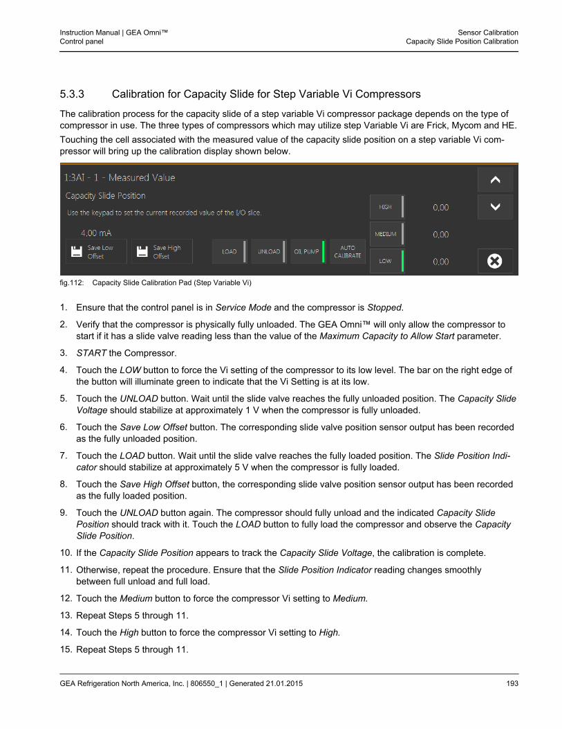
5.3.3 Calibration for Capacity Slide for Step Variable Vi Compressors
The calibration process for the capacity slide of a step variable Vi compressor package depends on the type ofcompressor in use. The three types of compressors which may utilize step Variable Vi are Frick, Mycom and HE.Touching the cell associated with the measured value of the capacity slide position on a step variable Vi com-pressor will bring up the calibration display shown below.
fig.112: Capacity Slide Calibration Pad (Step Variable Vi)
1. Ensure that the control panel is in Service Mode and the compressor is Stopped.
2. Verify that the compressor is physically fully unloaded. The GEA Omni™ will only allow the compressor tostart if it has a slide valve reading less than the value of the Maximum Capacity to Allow Start parameter.
3. START the Compressor.
4. Touch the LOW button to force the Vi setting of the compressor to its low level. The bar on the right edge ofthe button will illuminate green to indicate that the Vi Setting is at its low.
5. Touch the UNLOAD button. Wait until the slide valve reaches the fully unloaded position. The Capacity SlideVoltage should stabilize at approximately 1 V when the compressor is fully unloaded.
6. Touch the Save Low Offset button. The corresponding slide valve position sensor output has been recordedas the fully unloaded position.
7. Touch the LOAD button. Wait until the slide valve reaches the fully loaded position. The Slide Position Indi-cator should stabilize at approximately 5 V when the compressor is fully loaded.
8. Touch the Save High Offset button, the corresponding slide valve position sensor output has been recordedas the fully loaded position.
9. Touch the UNLOAD button again. The compressor should fully unload and the indicated Capacity SlidePosition should track with it. Touch the LOAD button to fully load the compressor and observe the CapacitySlide Position.
10. If the Capacity Slide Position appears to track the Capacity Slide Voltage, the calibration is complete.
11. Otherwise, repeat the procedure. Ensure that the Slide Position Indicator reading changes smoothlybetween full unload and full load.
12. Touch the Medium button to force the compressor Vi setting to Medium.
13. Repeat Steps 5 through 11.
14. Touch the High button to force the compressor Vi setting to High.
15. Repeat Steps 5 through 11.
Instruction Manual | GEA Omni™Control panel
Sensor CalibrationCapacity Slide Position Calibration
GEA Refrigeration North America, Inc. | 806550_1 | Generated 21.01.2015 193

16. The compressor may be taken out of Service mode and stopped if desired.
Sensor CalibrationCapacity Slide Position Calibration
Instruction Manual | GEA Omni™Control panel
194 GEA Refrigeration North America, Inc. | 806550_1 | Generated 21.01.2015
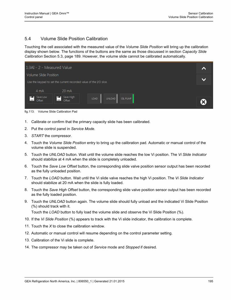
5.4 Volume Slide Position Calibration
Touching the cell associated with the measured value of the Volume Slide Position will bring up the calibrationdisplay shown below. The functions of the buttons are the same as those discussed in section Capacity SlideCalibration Section 5.3, page 189. However, the volume slide cannot be calibrated automatically.
fig.113: Volume Slide Calibration Pad
1. Calibrate or confirm that the primary capacity slide has been calibrated.
2. Put the control panel in Service Mode.
3. START the compressor.
4. Touch the Volume Slide Position entry to bring up the calibration pad. Automatic or manual control of thevolume slide is suspended.
5. Touch the UNLOAD button. Wait until the volume slide reaches the low Vi position. The Vi Slide Indicatorshould stabilize at 4 mA when the slide is completely unloaded.
6. Touch the Save Low Offset button, the corresponding slide valve position sensor output has been recordedas the fully unloaded position.
7. Touch the LOAD button. Wait until the Vi slide valve reaches the high Vi position. The Vi Slide Indicatorshould stabilize at 20 mA when the slide is fully loaded.
8. Touch the Save High Offset button, the corresponding slide valve position sensor output has been recordedas the fully loaded position.
9. Touch the UNLOAD button again. The volume slide should fully unload and the indicated Vi Slide Position(%) should track with it.Touch the LOAD button to fully load the volume slide and observe the Vi Slide Position (%).
10. If the Vi Slide Position (%) appears to track with the Vi slide indicator, the calibration is complete.
11. Touch the X to close the calibration window.
12. Automatic or manual control will resume depending on the control parameter setting.
13. Calibration of the Vi slide is complete.
14. The compressor may be taken out of Service mode and Stopped if desired.
Instruction Manual | GEA Omni™Control panel
Sensor CalibrationVolume Slide Position Calibration
GEA Refrigeration North America, Inc. | 806550_1 | Generated 21.01.2015 195
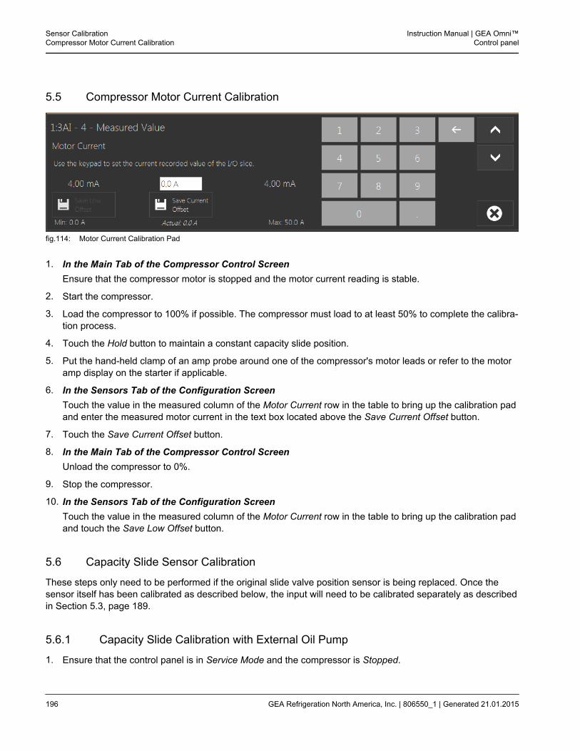
5.5 Compressor Motor Current Calibration
fig.114: Motor Current Calibration Pad
1. In the Main Tab of the Compressor Control ScreenEnsure that the compressor motor is stopped and the motor current reading is stable.
2. Start the compressor.
3. Load the compressor to 100% if possible. The compressor must load to at least 50% to complete the calibra-tion process.
4. Touch the Hold button to maintain a constant capacity slide position.
5. Put the hand-held clamp of an amp probe around one of the compressor's motor leads or refer to the motoramp display on the starter if applicable.
6. In the Sensors Tab of the Configuration ScreenTouch the value in the measured column of the Motor Current row in the table to bring up the calibration padand enter the measured motor current in the text box located above the Save Current Offset button.
7. Touch the Save Current Offset button.
8. In the Main Tab of the Compressor Control ScreenUnload the compressor to 0%.
9. Stop the compressor.
10. In the Sensors Tab of the Configuration ScreenTouch the value in the measured column of the Motor Current row in the table to bring up the calibration padand touch the Save Low Offset button.
5.6 Capacity Slide Sensor Calibration
These steps only need to be performed if the original slide valve position sensor is being replaced. Once thesensor itself has been calibrated as described below, the input will need to be calibrated separately as describedin Section 5.3, page 189.
5.6.1 Capacity Slide Calibration with External Oil Pump
1. Ensure that the control panel is in Service Mode and the compressor is Stopped.
Sensor CalibrationCompressor Motor Current Calibration
Instruction Manual | GEA Omni™Control panel
196 GEA Refrigeration North America, Inc. | 806550_1 | Generated 21.01.2015
2. Loosen the setscrews on the sides of the transducer and turn the device so the small cover is readily visible.An inspection mirror may be used in lieu of rotating the transducer.
3. Remove the small round cover from the transducer.
4. Before proceeding the transducer must have been powered for at least one minute.
5. The red LED should be flashing at about a ½ second rate if the indicator is functional. Ignore any green LEDactivity until the calibration is complete.
6. Initiate Oil Pump Test by touching theOIL PUMP button.
7. Touch the UNLOAD button and wait about 90 seconds for the slide valve to fully unload. Smaller machinesmay not require the full 90 seconds to unload.
8. The calibration button on the transducer is positioned between the two LEDs. Push and hold the calibrationbutton for five seconds, both LEDs should be off.
9. Press the pushbutton one time and release it. The red LED will now turn On, and remain On, for approxi-mately 3 seconds while the zero calibration point is stored. DO NOT move the slide valve until the red LEDturns off.
10. Touch the LOAD button and wait about 90 seconds for the slide valve to fully load. Smaller machines maynot require the full 90 seconds to load.
• This process must be completed quickly because the indicator will abandon the calibration after a periodof time. Please note the red LED will flash approximately ¼ second every 5 seconds indicating the indi-cator is active and that the calibration has not been fully completed.
11. Once the compressor is fully loaded, push the calibration button twice, and the red LED will flash rapidly forapproximately 3 seconds. Do not attempt to move slide valve until red LED turns Off. When the red LEDstops flashing the loaded position is set.
12. At this time the sensor will have an output of 20 mA. This can be verified on the Operating Data screen.
13. UNLOAD and LOAD the machine to confirm calibration. Refer to the Compressor Capacity on the OperatingData display. It should track the slide valve between 4 mA and 20 mA.
14. Exit oil pump test by touching the OIL PUMP button.
15. Reinstall the cover.
16. If the transducer was rotated, restore it to the original orientation and tighten the setscrews.
17. Return load/unload needle valves to their original positions to ensure proper slide valve movement.
5.6.2 Capacity Slide Calibration without External Oil Pump
1. Ensure that the control panel is in Service mode and the compressor is Stopped.
2. Loosen the setscrews on the sides of the transducer and turn the device so the small cover is readily visible.An inspection mirror may be used in lieu of rotating the transducer.
3. Remove the small round cover from the transducer.
4. Before proceeding the transducer must have been powered for at least one minute.
5. The red LED should be flashing at about a ½ second rate if the indicator is functional. Ignore any green LEDactivity until the calibration is complete.
Instruction Manual | GEA Omni™Control panel
Sensor CalibrationCapacity Slide Sensor Calibration
GEA Refrigeration North America, Inc. | 806550_1 | Generated 21.01.2015 197
6. Verify that the compressor is physically fully unloaded. The GEA Omni™ will prevent the compressor fromstarting if the slide valve position displayed is greater than 70 %. The Slide Valve Position may need to betemporarily recalibrated to 0 % to allow the machine to start.
7. Start the compressor and wait until the compressor is running and oil pressure has been established.
8. Touch the UNLOAD button and wait about 90 seconds for the slide valve to fully unload. Smaller machinesmay not require the full 90 seconds to unload.
9. The calibration button on the transducer is positioned between the two LEDs. Push and hold the calibrationbutton for five seconds, both LEDs should be off.
10. Press the pushbutton one time and release it. The red LED will now turn On, and remain On, for approxi-mately 3 seconds while the zero calibration point is stored. DO NOT move the slide valve until the red LEDturns off.
11. Touch the LOAD button and wait about 90 seconds for the slide valve to fully load. Smaller machines maynot require the full 90 seconds to load.
• This process must be completed quickly because the indicator will abandon the calibration after a periodof time. Please note the red LED will flash approximately ¼ second every 5 seconds indicating the indi-cator is active and that the calibration has not been fully completed.
12. Once the compressor is fully loaded, push the calibration button twice, and the red LED will flash rapidly forapproximately 3 seconds. Do not attempt to move slide valve until red LED turns Off. When the red LEDstops flashing the loaded position is set.
13. At this time the sensor will have an output of 20 mA. This can be verified on the Operating Data screen.
14. UNLOAD and LOAD the machine to confirm calibration. Refer to the Compressor Capacity on the OperatingData screen. It should track the slide valve between 4 mA and 20 mA.
15. Stop the compressor by touching STOP.
16. Reinstall the cover.
17. If the transducer was rotated, restore it to the original orientation and tighten the setscrews.
18. Return load/unload needle valves to their original positions to ensure proper slide valve movement.
Sensor Calibration
Instruction Manual | GEA Omni™Control panel
198 GEA Refrigeration North America, Inc. | 806550_1 | Generated 21.01.2015
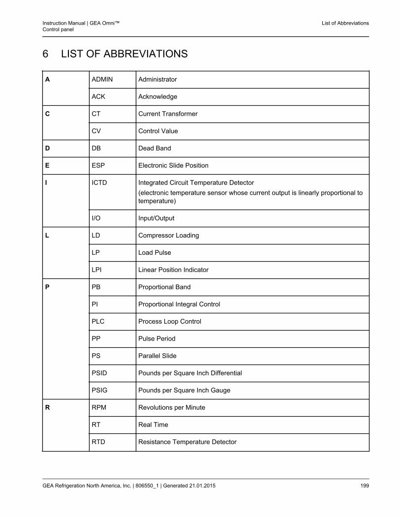
6 LIST OF ABBREVIATIONS
A ADMIN Administrator
ACK Acknowledge
C CT Current Transformer
CV Control Value
D DB Dead Band
E ESP Electronic Slide Position
I ICTD Integrated Circuit Temperature Detector(electronic temperature sensor whose current output is linearly proportional totemperature)
I/O Input/Output
L LD Compressor Loading
LP Load Pulse
LPI Linear Position Indicator
P PB Proportional Band
PI Proportional Integral Control
PLC Process Loop Control
PP Pulse Period
PS Parallel Slide
PSID Pounds per Square Inch Differential
PSIG Pounds per Square Inch Gauge
R RPM Revolutions per Minute
RT Real Time
RTD Resistance Temperature Detector
Instruction Manual | GEA Omni™Control panel
List of Abbreviations
GEA Refrigeration North America, Inc. | 806550_1 | Generated 21.01.2015 199
RTU Real Time Automation
S SP Set Point
T TS Tandem Slide
U UI User Interface
UL Compressor Unloading
UP Unload Pulse
V VI Volume Index
VNC Virtual Network Computing
List of Abbreviations
Instruction Manual | GEA Omni™Control panel
200 GEA Refrigeration North America, Inc. | 806550_1 | Generated 21.01.2015

Instruction Manual | GEA Omni™Control panel
List of Abbreviations
GEA Refrigeration North America, Inc. | 806550_1 | Generated 21.01.2015 201