Embed Size (px)
Citation preview

Doc. No. OSA 008U-09
GREASE LUBRICATOR SKR- 55 MODEL No.880870
WARNING Prior to operating this pump, be sure to read this operation manual for safety. After reading the manual, please keep it at hand any time for your quick reference.
INSTRUCTION

1 / 3
- Preface
Thank you very much for purchasing Yamada Pump. This machine is a portable type lubricator that is indispensable
for grease lubrication for machines and vehicles. This lubricator cannot be used for oil lubrication. The applicable
grease is limited to a type of NLGI No.0 or less in the normal operating conditions. If the lubricator is used in an
extremely cold or low-temperature environment, the discharge volume will be remarkably lowered. Silicone grease is
not applicable.
- For Safe Operation
This document describes the items that are important for the user to operate this product safety, correctly, and
efficiently. Before operating this product, read this manual thoroughly, in particular, “Warnings and Cautions” at the
beginning of this manual, with a good understanding of its contents. Keep this manual carefully in an easy-to-access
place so that the user may refer to it whenever necessary.
- Warnings and Cautions
To use this product safely, be sure to observe the contents of the following description. In this manual, warnings and
cautions are indicated by using symbols. These symbols are intended to prevent death or serious injury that may be
caused to the operator or those who are around the product and damage that may be caused to the articles that are
around the product, as well as to use the product safely and correctly. Each symbol is indicated and has a meaning as
shown below. Read the description with a good understanding of its contents.
WARNING : This indicates the existence of potential hazard which, if not avoided, will result in death or serious injury.
CAUTION : This indicates the existence of potential hazard which, if not avoided, may result in bodily injury or in physical damage.
To indicate the contents of danger and damage, the following symbols are used together with the above indications.
This symbol indicates an act that is prohibited (prohibition). The concrete contents of prohibition are indicated by the side of the indication.
This symbol indicates the contents that must be observed. The concrete contents of observance are indicated by the side of the indication.

2 / 3
- Precautions on Use
The following warnings and cautions are very important. Be sure to observe them.
WARNING - Keep your face away from the exhaust and discharge ports. Material may suddenly come out. There is
a possibility of losing eyesight if it strikes eyes.
- Keep your face and hands away from the outlet when handling the check valve. Air-containing material may suddenly come out. There is a possibility of losing eyesight and injuring the hand.
- Do not aim exhalation part of this product at any person. Residual pressure may be left inside the gun even when the pump is not in operation. There is a possibility of losing eyesight if it strikes eyes.
- Gasoline is a high volatile fuel. Do not use it to clean the pump in any case, otherwise ignition or explosion may be caused.
- Modification of this pump may lead to death, bodily injury, or a failure. Do not modify it in any case because it involves a risk.
- The operator and maintenance engineer should read the operation manual thoroughly before operating this product and performing maintenance in respect of this product.
- Always wear proper safety equipments (facemask, ear plugs, and safety shoes, etc.) when installing, operating, and disassembling this product.
- Lock caster's stopper during and after the work, so that this product should not move unexpectedly. Also, do not use or leave this product in a slope or any unstable locations. This product moves freely when the caster is not locked and the damage only accident and the facilities pollution, etc. might occur. Such a secondary disaster becomes a responsibility on the user side.
- Make ground connection when working with flammable material or in explosive atmosphere. Rapid pumping of material can result in static electrical charge. Also, be sure to provide proper ventilation where a flammable atmosphere may exist.
- Execute the daily checkup.
- Use this product according to the product specification.
- Attach a valve (for stop in emergency) or regulator to the air supply pipe to keep supply air pressure under 0.7MPa.
- Be careful not to drop the cabinet when lifting it up to replace a pail. Catching a falling cabinet may cause hand injury by its edge.
- Turn off the air supply to stop pump operation when removing the pump from a pail. Being caught in a shovel, the lowest part of the pump, can cause hand injury and malfunction of the pump.
- Discontinue it when you feel a hazard or abnormality during the work. And correspond according to the troubleshooting.
- Stop pump operation immediately when a drum becomes empty. Running the pump dry will cause excessive vibration, resulting in reduction of pump life and damage to other equipment.
- Be very careful not to drop the grease gun. It may become damaged, resulting in leakage and malfunction.

3 / 3
WARNING - Before maintenance operation, be sure to stop air from being supplied to the pump, and release the
internal pressure (both air and material) of the pump. There is danger such as spouting of the material when the maintenance work is done with air supplied.
- Do not discharge material directly onto the ground. Dispose of harmful materials according to the requirements specified in MSDS or local regulations. Also, dispose of this product according to the local regulations after removing residual material from inside this product. (Please contact industrial waste disposal service.)
CAUTION - Keep hands and fingers away from this product during operation to avoid injury from moving parts.
- Use this product for the material suitable for the specification. Parts may be corroded and material leak from the damaged parts can lead to environmental pollution. Also, follow handling notes (MSDS) of the manufacturer about the handling of the material used.
- Take protective measures against rainwater and dust. It is likely to lead to the pollution of the material.
- Watch your step around this product to avoid tripping over the base and casters.
- Be careful about your hands when mounting/dismounting the cabinet or installing a pail. The edges of the cabinet and pail may cause hand injury. Also, be careful about your posture when moving the pump or lifting the cabinet to avoid back injury.
- Material remaining inside or on the surface of the pump may spill out by inserting or removing the pump into/from a pail. Be very careful not to get your clothing dirty.
- Do not touch the surfaces of the pump and the hose when pumping high-temperature material. Risk of burns exists.
- Be careful when handling the grease gun. Avoid finger injury from being caught between the lever and gun. The finger might be injured.
- Stop the air supply source after the end of work when not using this pump for a long time such as nighttimes and holidays. Also, open the valve of the exhalation port and liberate pressure in the pump and the hose. There is a possibility of polluting facilities because of the damage of the hose and the leakage of the valve. Such a secondary disaster becomes a responsibility on the user side.
Table of Contents
- Preface
- For Safe Operation
- Warnings and Cautions
- Precautions on Use
- Table of Contents
1. Name of Parts 1.1 Name of parts ...................................................................................................................... 1 1.2 Contents of package............................................................................................................ 1
2. Preparations before Operation 2.1 Function of the Air Motor ..................................................................................................... 2 2.2 Function of the Lower Pump................................................................................................ 2
3. Preparations before Operation ........................................................................................... 3
4. How to Operate the Machine ............................................................................................... 4
5. Maintenance and Inspection 5.1 Troubleshooting and corrective measures........................................................................... 5 5.2 Maintenance and inspection ................................................................................................ 5 5.3 Disassembly and assembly ................................................................................................. 6
6. Parts Disassembly Drawing and Parts List 6.1 880870 SKR-55 .................................................................................................................. 7 6.2 852498 Pump assembly ..................................................................................................... 7 6.3 802630 Air motor ................................................................................................................ 8 6.4 851985 Grease gun ............................................................................................................ 9
7. Specification ............................................................................................................................ 10
8. Trouble Information Fax Form ............................................................................................ 11
9. Limited Warranty .................................................................................................................... 12

1
1. Names of Parts
1.1 Names of parts
1.2 Contents of package
The main devices and the accessories are packed in different cases.
Open the top part of the corrugated fiberboard case and check if the devices is not damaged and if accessories are
all contained in the package.

2
2. Principle of Operation
The YAMADA Air-powered Pump is a reciprocating type pump that is driven by compressed air. This pump consists of
an air motor to drive the pump and a lower pump to draw up the liquid material as shown in the figure.
2.1 Function of the Air Motor
1) In the status shown in the figure at right, the air piston reaches the
upper limit and is now about to go down.
2) The compressed air fed from the air supply port is applied to the
chamber A through the air passage tube from the path provided in the
lower part of the slide valve. The air pressure of the chamber B is
discharged out through the slide valve.
3) As a result, the air piston starts to go down.
4) When the air piston collides with the trip shoe, the slide valve is
momentarily tripped downward by the function of the trip mechanism.
5) As a result, the air supply is conducted to the chamber B and the
chamber A is conducted to the exhaust port, so that the air piston is
changed to go up.
6) Thus, the air motor continues its reciprocating motion automatically as
long as the supply air is fed to it.
2.2 Function of the Lower Pump
1) The lower pump integrated with the air motor traces the reciprocating
motion of the air motor.
2) The shovel performs mixing so that grease may be easily sucked into
the pump, and squeezes it into the foot valve.
3) Because the chamber D has a sectional area difference of the booster
piston, it sucks the grease from the shovel at the ascending motion. At
the descending motion, the foot valve is closed, so that the grease of
the chamber D is fed out to the chamber C.
4) Because the chamber C leads to the discharge port, the grease is
intermittently discharged to the delivery side.
5) This reciprocating motion is automatically continued until the delivery
side is closed and the material compressive force of the chamber C
and chamber D is completely balanced with the pressure of the air
motor.

3
3. Preparations before Operation
1) First loosen the pan-head screw and take out the pump from the cabinet.
Remove the rubber cap at the bottom of the pump assembly, insert the
pump into the cabinet, and fix it with a pan-head screw.
<Assembly of Equipment> indicated on the top surface of the corrugated
fiberboard case. (Fig. 1)
2) Loosen the two clamping nuts at the bottom of the cabinet (turn them
counterclockwise), and remove the cabinet from the base frame. (Fig. 2)
3) Place a pail in the middle of the base frame and install the cabinet as it
was. Tighten the clamping nuts on both sides equally.
4) Connect the attached high-pressure hose and grease gun to the discharge
port of the pump.
5) When the air coupler is connected to the pump, the pump and hose will be
filled with grease. After that, the pump operation will stop.
6) The first applied grease includes the internal air of the pump. This is not a
good condition. Obtain a perfect condition by the next operation.
First open the check valve and operate the pump until grease is
discharged from a small hole under the check valve. (Fig. 3)
At this time, spread paper so that grease may not come into touch with the
hand, and dispose of the discharged grease.
<NOTE>
・ The grease in which air is mixed is cloudy in white.
Fig. 1
Fig. 3
Fig. 2
4
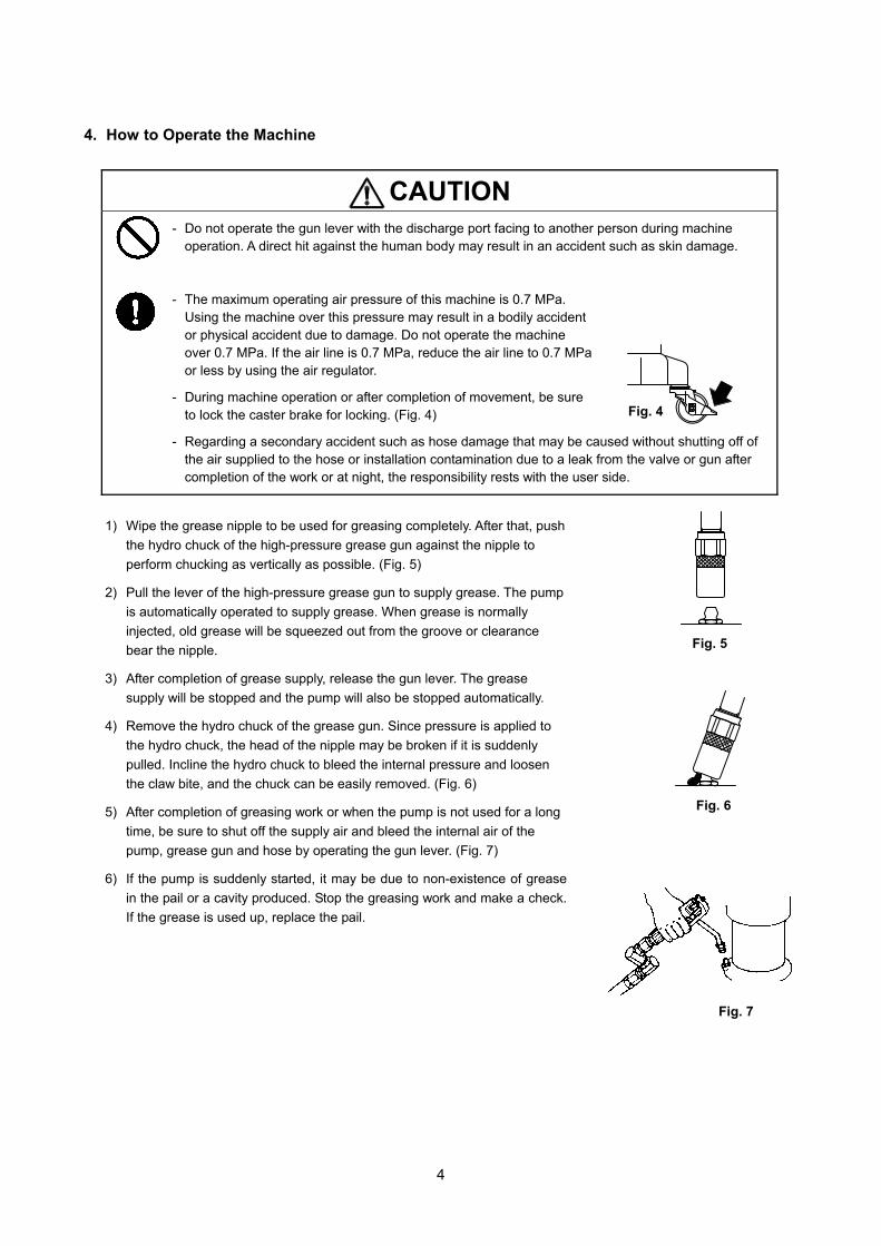
4. How to Operate the Machine
CAUTION - Do not operate the gun lever with the discharge port facing to another person during machine
operation. A direct hit against the human body may result in an accident such as skin damage.
- The maximum operating air pressure of this machine is 0.7 MPa. Using the machine over this pressure may result in a bodily accident or physical accident due to damage. Do not operate the machine over 0.7 MPa. If the air line is 0.7 MPa, reduce the air line to 0.7 MPa or less by using the air regulator.
- During machine operation or after completion of movement, be sure to lock the caster brake for locking. (Fig. 4)
- Regarding a secondary accident such as hose damage that may be caused without shutting off of the air supplied to the hose or installation contamination due to a leak from the valve or gun after completion of the work or at night, the responsibility rests with the user side.
1) Wipe the grease nipple to be used for greasing completely. After that, push
the hydro chuck of the high-pressure grease gun against the nipple to
perform chucking as vertically as possible. (Fig. 5)
2) Pull the lever of the high-pressure grease gun to supply grease. The pump
is automatically operated to supply grease. When grease is normally
injected, old grease will be squeezed out from the groove or clearance
bear the nipple.
3) After completion of grease supply, release the gun lever. The grease
supply will be stopped and the pump will also be stopped automatically.
4) Remove the hydro chuck of the grease gun. Since pressure is applied to
the hydro chuck, the head of the nipple may be broken if it is suddenly
pulled. Incline the hydro chuck to bleed the internal pressure and loosen
the claw bite, and the chuck can be easily removed. (Fig. 6)
5) After completion of greasing work or when the pump is not used for a long
time, be sure to shut off the supply air and bleed the internal air of the
pump, grease gun and hose by operating the gun lever. (Fig. 7)
6) If the pump is suddenly started, it may be due to non-existence of grease
in the pail or a cavity produced. Stop the greasing work and make a check.
If the grease is used up, replace the pail.
Fig. 4
Fig. 5
Fig. 6
Fig. 7

5
5. Maintenance and Inspection
5.1 Troubleshooting and corrective measures
5.2 Maintenance and inspection
■Oiling
For lubrication of the pump, perform oiling with a lubricant once every 10 days. Apply the lubricant as follows.
1) Remove the air regulator.
2) Inject several drops (approx. 0.5ml) of lubricant to the air supply port as shown in
the figure at right. (Fig. 8)
Use turbine oil first class ISO(VG-32) as the lubricant.
■Inspection
・ The hose is a consumable part. Check it periodically. If any blemish or leakage is
found, replace the hose little earlier.
・ The packing and slide portion parts of the pump are worn away. Check and
replace them once a year.
Fig. 8
Symptom CauseContents of inspection
and corrective measure.Check if the supply air pressure is normal. Adjust the supply air pressure
between 0.3 and 0.7 MPa.
↓(Operate the pumpwith the discharge-side hose removed.)
→ If the pump is operated,
the outlet valve of the hose is clogged.
→ If the pump is not operated, the pump is defective.
Ask the dealer to repair it.
Check if grease is in the pail. Supply grease.Check if a cavity is produced in the suction tube. Gather grease toward the middle.The lower pump is defective. Ask the dealer to repair it.Check if the supply air pressure is lowered. Check the supply air pressure.The lower pump is defective. Ask the dealer to repair it.Check the discharge-side hoseand connecting section for leakage.
Check the hoseand the connecting section.
Check if the grease in the pail has been used up. Supply or replace grease.The lower pump is defective. Ask the dealer to repair it.
The pump cannot be operated.
Grease comes outbut the flow rate is low.The pump is continuouslyoperated without stop.(even if the outlet valveis closed)
The pump is operatedbut no grease comes out.

6
5.3 Disassembly and assembly
WARNING - Gasoline is a high-volatility material. Do not use gasoline to clean the pump in any case, otherwise it
may cause ignition or explosion.
- When washing parts, do not use such a liquid as corrodes aluminum, copper alloy, iron, etc.
- When disassembling and checking the pump, be sure to stop the supply air and open the outlet valve to release the internal pressure of the pump beforehand.
- Some types of grease may contain a carcinogenic material. Read the cautions for handling grease given by the grease maker carefully when handling the grease.
※ When the pump operation becomes defective or stops, do not disassemble
the pump thoughtlessly but judge the condition carefully by referring to the
item pertaining to <Troubleshooting and Corrective Measures>.
※ If the foot valve is clogged with dust or the like, perform disassembling,
washing and inspection according to the following procedure.
※ For disassembling parts other than the foot valve and the air motor, ask
the dealer for disassembly
[Disassembling the foot valve]
1) Bleed the internal pressure of the pump and hose and remove the air
chuck and high-pressure hose form the pump.
2) Unscrew the pan-head screw of the body supporter that fixes the pump.
Pull out the pump from above. (Fig. 9)
3) Fix the main body of the pump on the vise and set a spanner on the valve
adapter. Set a pipe wrench on the tube and unscrew the tube.
4) Pull out the split pin that fixes the plate and unscrew the nut. The plate can
be removed. (Fig.10)
5) Set a spanner on the valve adapter and unscrew it. The valve seat, foot
valve and washer can be taken out from the suction tube.
6) If they are hard to take out, set a pipe wrench on the knurling of the suction
tube and unscrew the suction tube.
7) Pull apart the suction tube a little, and the union connecting between the
air motor and the rod becomes visible. Pull out the pin and unscrew it for
removal. (Fig.11)
8) The air motor is separated from the lower pump. The valve seat, foot valve
and washer can be taken out from the inside of the suction tube. (Fig.12)
9) Wash and check each part. If any blemish or wear is found, replace the
part with a new one. In particular, pay attention to filter clogging in valve
adapter.
10) For assembling, reverse the disassembling procedure. At this time,
perform inspection taking care about the directions of the valve seat
and foot valve.
Fig. 9
Fig.10
Fig.11
Fig.12

7
NO. PARTS NO. DESCRIPTION Q'TY
1 681170 Silencer 12 802630 Air motor 13 803358 Lower pump -
3-1 702971 Pin 33-2 706091 Union 13-3 702985 Suction tube 13-4 702986 Rod 13-5 702975 Union 13-6 702974 Stop washer 13-7 702976 Spring 13-8 630313 Ball 13-9 803355 Cylinder assembly 13-10 702977 Washer 23-11 632754 Spring pin 13-12 706072 Foot tube 13-13 702980 Valve ring 13-14 706399 Plunger rod 13-15 771404 Foot valve 13-16 702982 Valve seat 13-17 830407 Valve adapter assembly 13-18 702983 Tube 13-19 702984 Plate 13-20 627010 Nut 13-21 632019 Cotter pin 1
4 770409 Packing 15 711650 Out tube 1
NO. PARTS NO. DESCRIPTION Q'TY
1 852498 Pump assembly 12 800766 Check valve 13 695034 High-pressure hose 14 851985 Grease gun 15 680743 Air coupler 16 830138 Gun holder 17 705841 Handle 18 702779 Grease nipple 19 631013 Plain washer 2
10 682276 Nut 211 706076 Cabinet 112 602296 Pan-head screw 113 704570 Clamping nut 214 831098 Base frame 115 681767 Caster (with brake) 216 680136 Caster 2
6. Parts Disassembly Drawing and Parts List
6.1 880870 SKR-55
■Parts List
6.2 852498 Pump assembly
■Parts List

8
NO. PARTS NO. DESCRIPTION Q'TY NO. PARTS NO. DESCRIPTION Q'TY
1 701768 Elbow 2 18 704893 Spring holder 12 708523 Pipe 1 19 710672 Cap 13 708311 Bonnet 1 20 701825 Spring 14 701811 Cap nut 1 21 705661 Trip shoe guide 15 701815 Washer 1 22 682976 O ring 16 770180 Packing 2 23 710949 Washer 17 701810 Washer 1 24 771405 Back up ring 18 701823 Block 1 25 771418 Packing 19 770181 Packing 1 26 711384 Collar 1
10 701822 Valve seat 1 27 701816 Valve supporter 111 705659 Trip shoe 1 28 681768 Screw (w/spring) 212 710950 Body 1 29 590085 Guide plate 113 706068 Spindle 1 30 701766 Tube gland 214 706067 Bushing 1 31 701765 Sleeve 215 640012 O ring 1 32 702582 Washer 216 706066 Gland housing 1 33 683629 O ring 1
17 770182 O ring 1
6.3 802630 Air motor
■Parts List
<NOTE>
- If disassembly is required, ask the dealer to disassemble the air motor.
- As for the specialist of the dissolution, refer to the instruction manual.
(Separately APP006U: Instruction for Grease Pump)

9
NO. PARTS NO. DESCRIPTION Q'TY
1 627641 Nut 12 711750 Bolt 13 711354 Lever 14 711444 Retaining nut 15 772160 Packing 26 713638 Washer 17 711357 Rod 18 711352 Body 19 711351 Link 1
10 683201 Rivet 211 804911 Nozzle 112 685728 Cap 113 630314 Ball 114 711445 Spring retainer 115 711446 Spring 116 640011 O ring 117 710971 Union 118 802910 Swivel joint assembly 1
6.4 851985 Grease gun
■Parts List
★No.3, 8, 9 and No.10 are undissolution.

10
7. Specification
■Engineering Data
■Performance Curve(only the pump) ■Dimensions
NOTE The continuous pump operation should be avoided if the desired delivery is in the range shaded in the figure below.
SKR-5588087055 x 1
MATERIAL CONNECTION DISCHARGE PORT High Pressure Grease Gun
AIR CONNECTION SUPPLY PORT Coupler Plug PS-20PM
0.2 ~ 0.7 MPaA-WEIGHTED SOUNDPRESSURE LEVEL *1
86 dB
A-WEIGHTED SOUNDPOWER LEVEL *2
96 dB
ENV. TEMPERATURE 0 ~ 60 ℃MATERIAL TEMP. 0 ~ 80 ℃
13.5 kg695034 High Pressure Hose 1/4×2.5m851985 High Pressure Grease Gun680743 Air Coupler(PS-20PM)
*1 Measurement method of A-weighted sound pressure level is based on ISO 1996.
*2 Measurement method of A-weighted sound power level is based on ISO 3744.
ACCESSORIES
AMB. TEMP. RANGE
OPERATING AIR PRESSURE
MAXIMUMOPERATING NOISE
TYPEMODEL No.PUMP RATIO (NOMINAL)
WEIGHT

11
8. Trouble Information Fax Form
Complete necessary information in the following fax form since your information is necessary to find the cause of the trouble or failure and it enriches our repair services. After filling it, send it to us.
Trouble Information Fax Form
Company name
Name
Department name
Address
Contact information
Tel. ( ) -
Fax. ( ) -
Product name
Model
Duration of use 20 year month to year month
SERIAL No. (LOT No.)
Operation frequency □Continuous
□Intermittent hour/day/week/month
Purchase date Sales outlet
Machine conditions (descriptions of the trouble)

12
9. Limited Warranty
If an abnormality occurs during normal operation in accordance with the operating instructions and other operating
cautions within the warranty period (12 months after date of purchase) that can be attributed to a manufacturing
defect, the defective parts of this product will be serviced or the product will be replaced free of charge. However,
this warranty will not cover compensation for incidental damage or any malfunction listed below.
1. Warranty period
This warranty will be valid for a period of 12 months after the date of purchase.
2. Warranty
If, during the warranty period, any of the material of the genuine parts of this product or the workmanship of this
product is found defective, and is so verified by our company, the servicing cost will be fully born by our company.
3. Exclusion
Even during the warranty period, this warranty does not cover the following:
1) Malfunction arising from use of parts other than manufacturer-specified genuine parts
2) Malfunction arising from misuse or operating errors, or lack of storage or maintenance care
3) Malfunction arising from use with a fluid that may cause corrosion, inflation or dissolution of the component
parts of the product
4) Irregularity arising from repair made by other than by our firm, our regional office, dealer or authorized service
personnel
5) Malfunction arising from modification of the product by other than authorized service personnel
6) Wear and tear of parts that must be regularly replaced in the course of normal operation, such as packings,
O-rings, balls, and valve seats
7) Malfunction and/or damage due to transportation, moving or droppage of the product after purchase
8) Malfunction and/or damage due to fire, earthquake, flood or other force majeure
9) Malfunction arising from use of compressed air that contains impurities or excessive moisture, or use of
gases or fluids other than the specified compressed air
10) Malfunction arising from use with a fluid that causes excessive abrasion or use of lubricating oil other than
that specified for this product
Furthermore, this warranty does not cover the rubber parts, or other parts that are subject to wear in normal
operation, used in this product and its accessories.
4. Parts
Parts for this product will be kept available for 5 years after discontinuation of production. Once 5 years have
elapsed after close of production, availability of parts for this product cannot be guaranteed.

201109 OSA008U
Manufactured by YAMADA CORPORATION
INTERNATIONAL DEPARTMENT No.1-3, 1-Chome, Mimami-Magome, Ohta-Ku, Tokyo, 143-8504, Japan
PHONE : +81-(0)3-3777-0241
FAX : +81-(0)3-3777-0584
YAMADA EUROPE B.V.
Aquamarijnstraat 50, 7554 NS Hengelo (0), The Netherlands
PHONE : 31(0) 74-2422032
FAX : 31(0) 74-2421055

![RETROFIT for ALPHA LUBRICATOR - Bosung221]20071120173954.pdf · PUMP STATION Build up oil pressure(40-50 bar) LUBRICATOR UNIT Oil Injection ALCU (Alpha Lubricator Cont. Unit) Master](https://img.pdfslide.us/doc/110x75/5aa2423d7f8b9ab4208ccd74/retrofit-for-alpha-lubricator-22120071120173954pdfpump-station-build-up-oil.jpg)