Embed Size (px)
Citation preview
Part No. D26120-025-0
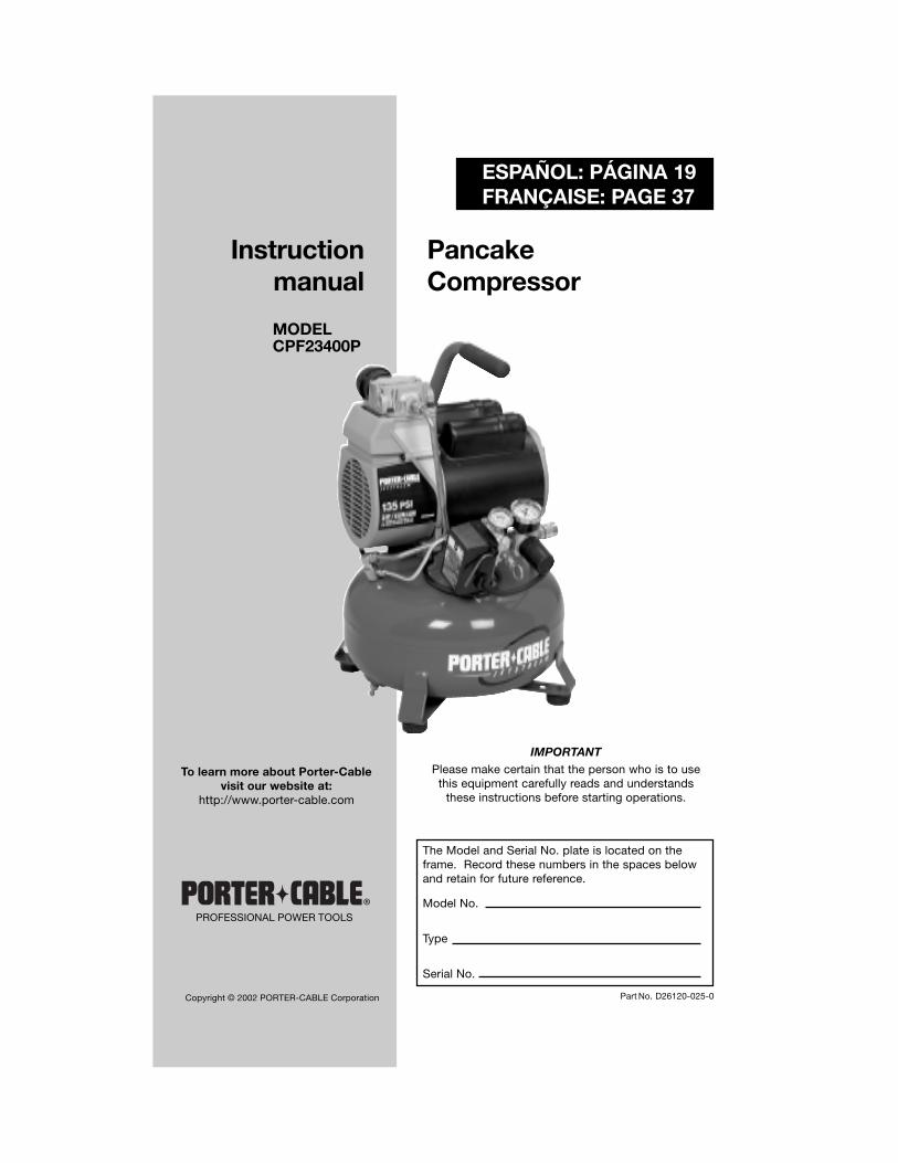
PancakeCompressor
Instructionmanual
To learn more about Porter-Cablevisit our website at:
http://www.porter-cable.com
The Model and Serial No. plate is located on theframe. Record these numbers in the spaces belowand retain for future reference.
Model No.
Type
Serial No.
ESPAÑOL: PÁGINA 19FRANÇAISE: PAGE 37
IMPORTANTPlease make certain that the person who is to usethis equipment carefully reads and understands
these instructions before starting operations.
PROFESSIONAL POWER TOOLS
Copyright © 2002 PORTER-CABLE Corporation
MODELCPF23400P
2-ENG
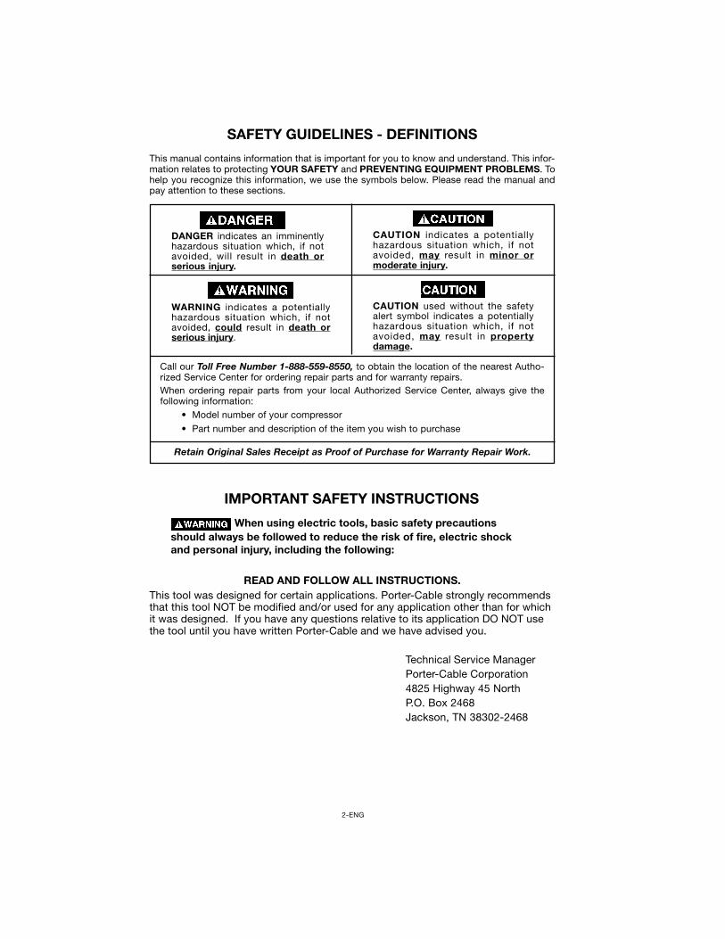
CAUTION indicates a potentiallyhazardous situation which, if notavoided, may result in minor ormoderate injury.
This manual contains information that is important for you to know and understand. This infor-mation relates to protecting YOUR SAFETY and PREVENTING EQUIPMENT PROBLEMS. Tohelp you recognize this information, we use the symbols below. Please read the manual andpay attention to these sections.
DANGER indicates an imminentlyhazardous situation which, if notavoided, will result in death orserious injury.
CAUTION used without the safetyalert symbol indicates a potentiallyhazardous situation which, if notavoided, may result in propertydamage.
WARNING indicates a potentiallyhazardous situation which, if notavoided, could result in death orserious injury.
Call our Toll Free Number 1-888-559-8550, to obtain the location of the nearest Autho-rized Service Center for ordering repair parts and for warranty repairs.When ordering repair parts from your local Authorized Service Center, always give thefollowing information:
• Model number of your compressor
• Part number and description of the item you wish to purchase
Retain Original Sales Receipt as Proof of Purchase for Warranty Repair Work.
SAFETY GUIDELINES - DEFINITIONS
IMPORTANT SAFETY INSTRUCTIONS
When using electric tools, basic safety precautionsshould always be followed to reduce the risk of fire, electric shockand personal injury, including the following:
READ AND FOLLOW ALL INSTRUCTIONS.This tool was designed for certain applications. Porter-Cable strongly recommendsthat this tool NOT be modified and/or used for any application other than for whichit was designed. If you have any questions relative to its application DO NOT usethe tool until you have written Porter-Cable and we have advised you.
Technical Service ManagerPorter-Cable Corporation4825 Highway 45 NorthP.O. Box 2468Jackson, TN 38302-2468
3-ENG
RISK OF BURSTING
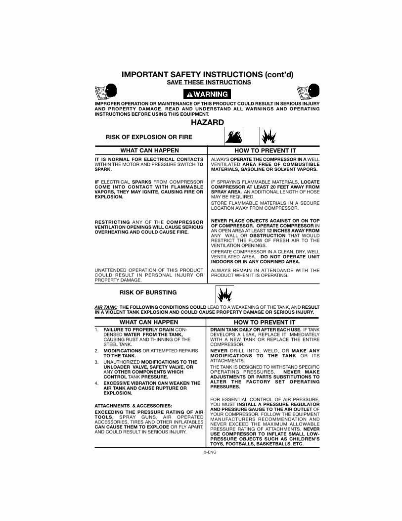
IT IS NORMAL FOR ELECTRICAL CONTACTSWITHIN THE MOTOR AND PRESSURE SWITCH TOSPARK.
IF ELECTRICAL SPARKS FROM COMPRESSORCOME INTO CONTACT WITH FLAMMABLEVAPORS, THEY MAY IGNITE, CAUSING FIRE OREXPLOSION.
RESTRICTING ANY OF THE COMPRESSORVENTILATION OPENINGS WILL CAUSE SERIOUSOVERHEATING AND COULD CAUSE FIRE.
UNATTENDED OPERATION OF THIS PRODUCTCOULD RESULT IN PERSONAL INJURY ORPROPERTY DAMAGE.
ALWAYS OPERATE THE COMPRESSOR IN A WELLVENTILATED AREA FREE OF COMBUSTIBLEMATERIALS, GASOLINE OR SOLVENT VAPORS.
IF SPRAYING FLAMMABLE MATERIALS, LOCATECOMPRESSOR AT LEAST 20 FEET AWAY FROMSPRAY AREA. AN ADDITIONAL LENGTH OF HOSEMAY BE REQUIRED.STORE FLAMMABLE MATERIALS IN A SECURELOCATION AWAY FROM COMPRESSOR.
NEVER PLACE OBJECTS AGAINST OR ON TOPOF COMPRESSOR. OPERATE COMPRESSOR INAN OPEN AREA AT LEAST 12 INCHES AWAY FROMANY WALL OR OBSTRUCTION THAT WOULDRESTRICT THE FLOW OF FRESH AIR TO THEVENTILATION OPENINGS.OPERATE COMPRESSOR IN A CLEAN, DRY, WELLVENTILATED AREA. DO NOT OPERATE UNITINDOORS OR IN ANY CONFINED AREA.
ALWAYS REMAIN IN ATTENDANCE WITH THEPRODUCT WHEN IT IS OPERATING.
SAVE THESE INSTRUCTIONS
IMPROPER OPERATION OR MAINTENANCE OF THIS PRODUCT COULD RESULT IN SERIOUS INJURYAND PROPERTY DAMAGE. READ AND UNDERSTAND ALL WARNINGS AND OPERATINGINSTRUCTIONS BEFORE USING THIS EQUIPMENT.
RISK OF EXPLOSION OR FIRE
AIR TANK: THE FOLLOWING CONDITIONS COULD LEAD TO A WEAKENING OF THE TANK, AND RESULTIN A VIOLENT TANK EXPLOSION AND COULD CAUSE PROPERTY DAMAGE OR SERIOUS INJURY.
HAZARD
WHAT CAN HAPPEN HOW TO PREVENT IT
IMPORTANT SAFETY INSTRUCTIONS (cont’d)
DRAIN TANK DAILY OR AFTER EACH USE. IF TANKDEVELOPS A LEAK, REPLACE IT IMMEDIATELYWITH A NEW TANK OR REPLACE THE ENTIRECOMPRESSOR.NEVER DRILL INTO, WELD, OR MAKE ANYMODIFICATIONS TO THE TANK OR ITSATTACHMENTS.THE TANK IS DESIGNED TO WITHSTAND SPECIFICOPERATING PRESSURES. NEVER MAKEADJUSTMENTS OR PARTS SUBSTITUTIONS TOALTER THE FACTORY SET OPERATINGPRESSURES.
FOR ESSENTIAL CONTROL OF AIR PRESSURE,YOU MUST INSTALL A PRESSURE REGULATORAND PRESSURE GAUGE TO THE AIR OUTLET OFYOUR COMPRESSOR. FOLLOW THE EQUIPMENTMANUFACTURERS RECOMMENDATION ANDNEVER EXCEED THE MAXIMUM ALLOWABLEPRESSURE RATING OF ATTACHMENTS. NEVERUSE COMPRESSOR TO INFLATE SMALL LOW-PRESSURE OBJECTS SUCH AS CHILDREN’STOYS, FOOTBALLS, BASKETBALLS. ETC.
1. FAILURE TO PROPERLY DRAIN CON-DENSED WATER FROM THE TANK,CAUSING RUST AND THINNING OF THESTEEL TANK.
2. MODIFICATIONS OR ATTEMPTED REPAIRSTO THE TANK.
3. UNAUTHORIZED MODIFICATIONS TO THEUNLOADER VALVE, SAFETY VALVE, ORANY OTHER COMPONENTS WHICHCONTROL TANK PRESSURE.
4. EXCESSIVE VIBRATION CAN WEAKEN THEAIR TANK AND CAUSE RUPTURE OREXPLOSION.
ATTACHMENTS & ACCESSORIES:EXCEEDING THE PRESSURE RATING OF AIRTOOLS, SPRAY GUNS, AIR OPERATEDACCESSORIES, TIRES AND OTHER INFLATABLESCAN CAUSE THEM TO EXPLODE OR FLY APART,AND COULD RESULT IN SERIOUS INJURY.
WHAT CAN HAPPEN HOW TO PREVENT IT
4-ENG
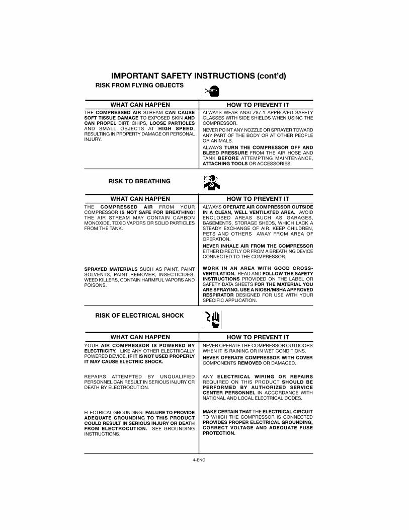
RISK FROM FLYING OBJECTSIMPORTANT SAFETY INSTRUCTIONS (cont’d)
THE COMPRESSED AIR STREAM CAN CAUSESOFT TISSUE DAMAGE TO EXPOSED SKIN ANDCAN PROPEL DIRT, CHIPS, LOOSE PARTICLESAND SMALL OBJECTS AT HIGH SPEED ,RESULTING IN PROPERTY DAMAGE OR PERSONALINJURY.
ALWAYS WEAR ANSI Z87.1 APPROVED SAFETYGLASSES WITH SIDE SHIELDS WHEN USING THECOMPRESSOR.NEVER POINT ANY NOZZLE OR SPRAYER TOWARDANY PART OF THE BODY OR AT OTHER PEOPLEOR ANIMALS.ALWAYS TURN THE COMPRESSOR OFF ANDBLEED PRESSURE FROM THE AIR HOSE ANDTANK BEFORE ATTEMPTING MAINTENANCE,ATTACHING TOOLS OR ACCESSORIES.
WHAT CAN HAPPEN HOW TO PREVENT IT
THE COMPRESSED AIR FROM YOURCOMPRESSOR IS NOT SAFE FOR BREATHING!THE AIR STREAM MAY CONTAIN CARBONMONOXIDE, TOXIC VAPORS OR SOLID PARTICLESFROM THE TANK.
SPRAYED MATERIALS SUCH AS PAINT, PAINTSOLVENTS, PAINT REMOVER, INSECTICIDES,WEED KILLERS, CONTAIN HARMFUL VAPORS ANDPOISONS.
ALWAYS OPERATE AIR COMPRESSOR OUTSIDEIN A CLEAN, WELL VENTILATED AREA. AVOIDENCLOSED AREAS SUCH AS GARAGES,BASEMENTS, STORAGE SHEDS, WHICH LACK ASTEADY EXCHANGE OF AIR. KEEP CHILDREN,PETS AND OTHERS AWAY FROM AREA OFOPERATION.NEVER INHALE AIR FROM THE COMPRESSOREITHER DIRECTLY OR FROM A BREATHING DEVICECONNECTED TO THE COMPRESSOR.
WORK IN AN AREA WITH GOOD CROSS-VENTILATION. READ AND FOLLOW THE SAFETYINSTRUCTIONS PROVIDED ON THE LABEL ORSAFETY DATA SHEETS FOR THE MATERIAL YOUARE SPRAYING. USE A NIOSH/MSHA APPROVEDRESPIRATOR DESIGNED FOR USE WITH YOURSPECIFIC APPLICATION.
RISK TO BREATHING
WHAT CAN HAPPEN HOW TO PREVENT IT
YOUR AIR COMPRESSOR IS POWERED BYELECTRICITY. LIKE ANY OTHER ELECTRICALLYPOWERED DEVICE, IF IT IS NOT USED PROPERLYIT MAY CAUSE ELECTRIC SHOCK.
REPAIRS ATTEMPTED BY UNQUALIFIEDPERSONNEL CAN RESULT IN SERIOUS INJURY ORDEATH BY ELECTROCUTION.
ELECTRICAL GROUNDING: FAILURE TO PROVIDEADEQUATE GROUNDING TO THIS PRODUCTCOULD RESULT IN SERIOUS INJURY OR DEATHFROM ELECTROCUTION. SEE GROUNDINGINSTRUCTIONS.
NEVER OPERATE THE COMPRESSOR OUTDOORSWHEN IT IS RAINING OR IN WET CONDITIONS.NEVER OPERATE COMPRESSOR WITH COVERCOMPONENTS REMOVED OR DAMAGED.
ANY ELECTRICAL WIRING OR REPAIRSREQUIRED ON THIS PRODUCT SHOULD BEPERFORMED BY AUTHORIZED SERVICECENTER PERSONNEL IN ACCORDANCE WITHNATIONAL AND LOCAL ELECTRICAL CODES.
MAKE CERTAIN THAT THE ELECTRICAL CIRCUITTO WHICH THE COMPRESSOR IS CONNECTEDPROVIDES PROPER ELECTRICAL GROUNDING,CORRECT VOLTAGE AND ADEQUATE FUSEPROTECTION.
RISK OF ELECTRICAL SHOCK
WHAT CAN HAPPEN HOW TO PREVENT IT
5-ENG
RISK FROM MOVING PARTS
RISK OF BURNS
RISK OF FALLING
IMPORTANT SAFETY INSTRUCTIONS (cont’d)
WHAT CAN HAPPEN HOW TO PREVENT IT
WHAT CAN HAPPEN HOW TO PREVENT IT
WHAT CAN HAPPEN HOW TO PREVENT IT
MOVING PARTS SUCH AS THE PULLEY,FLYWHEEL, AND BELT CAN CAUSE SERIOUSINJURY IF THEY COME INTO CONTACT WITH YOUOR YOUR CLOTHING.
ATTEMPTING TO OPERATE COMPRESSOR WITHDAMAGED OR MISSING PARTS OR ATTEMPTINGTO REPAIR COMPRESSOR WITH PROTECTIVESHROUDS REMOVED CAN EXPOSE YOU TOMOVING PARTS AND CAN RESULT IN SERIOUSINJURY.
TOUCHING EXPOSED METAL SUCH AS THECOMPRESSOR HEAD OR OUTLET TUBES, CANRESULT IN SERIOUS BURNS.
NEVER OPERATE THE COMPRESSOR WITHGUARDS OR COVERS WHICH ARE DAMAGED ORREMOVED.
ANY REPAIRS REQUIRED ON THIS PRODUCTSHOULD BE PERFORMED BY AUTHORIZEDSERVICE CENTER PERSONNEL.
NEVER TOUCH ANY EXPOSED METAL PARTS ONCOMPRESSOR DURING OR IMMEDIATELY AFTEROPERATION. COMPRESSOR WILL REMAIN HOTFOR SEVERAL MINUTES AFTER OPERATION.DO NOT REACH AROUND PROTECTIVE SHROUDSOR ATTEMPT MAINTENANCE UNTIL UNIT HASBEEN ALLOWED TO COOL.
A PORTABLE COMPRESSOR CAN FALL FROM ATABLE, WORKBENCH OR ROOF CAUSINGDAMAGE TO THE COMPRESSOR AND COULDRESULT IN SERIOUS INJURY OR DEATH TO THEOPERATOR OR BYSTANDERS.
ALWAYS OPERATE COMPRESSOR IN A STABLESECURE POSITION TO PREVENT ACCIDENTALMOVEMENT OF THE UNIT. NEVER OPERATECOMPRESSOR ON A ROOF OR OTHER ELEVATEDPOSITION. USE ADDITIONAL AIR HOSE TOREACH HIGH LOCATIONS.
WHAT CAN HAPPEN HOW TO PREVENT IT
RISK OF PROPERTY DAMAGE WHENTRANSPORTING COMPRESSOR
(Fire, Inhalation, Damageto Vehicle Surfaces)
OIL CAN LEAK OR SPILL AND COULD RESULTIN FIRE OR BREATHING HAZARD, SERIOUSINJURY OR DEATH CAN RESULT. OIL LEAKS WILLDAMAGE CARPET, PAINT OR OTHER SURFACESIN VEHICLES OR TRAILERS.
ALWAYS PLACE COMPRESSOR ON A PROTECTIVEMAT WHEN TRANSPORTING TO PROTECTAGAINST DAMAGE TO VEHICLE FROM LEAKS.REMOVE COMPRESSOR FROM VEHICLEIMMEDIATELY UPON ARRIVAL AT YOURDESTINATION.
ESWESWESWESWESW-99 — 9/26/99-99 — 9/26/99-99 — 9/26/99-99 — 9/26/99-99 — 9/26/99
6-ENG
CFM: Cubic feet per minute.SCFM: Standard cubic feet per minute; a unit of measure of air delivery.PSIG: Pounds per square inch gauge; a unit of measure of pressure.ASME: American Society of Mechanical Engineers; made, tested, inspected, andregistered to meet the standards of ASME.California Code: Unit may comply with California Code 462 (l) (2)/(M) (2).Specification/model label is on the side of the tank on units that comply withCalifornia Code.Cut-In Pressure: While the motor is off, air tank pressure drops as you continue touse your accessory or air tool. When the tank pressure drops to a certain low levelthe motor will restart automatically. The low pressure at which the motorautomatically restarts is called “cut-in pressure.”Cut-Out Pressure: When you turn on your air compressor and it begins to run, airpressure in the air tank begins to build. It builds to a certain high pressure beforethe motor automatically shuts off - protecting your air tank from pressure higherthan its capacity. The high pressure at which the motor shuts off is called “cut-outpressure.”Code Certification: Products that bear one or more of the following marks: UL,CUL, ETL, CETL, have been evaluated by OSHA certified indepenent safetylaboratories and meet the applicable Underwriters Laboratories Standards forSafety.
Porter-Cable air compressors should be operated on not more than a 50% dutycycle. This means an air compressor that pumps air more than 50% of one hour isconsidered misuse, because the air compressor is undersized for the required airdemand. Maximum compressor pumping time per hour is 30 minutes.
GLOSSARY
DUTY CYCLE
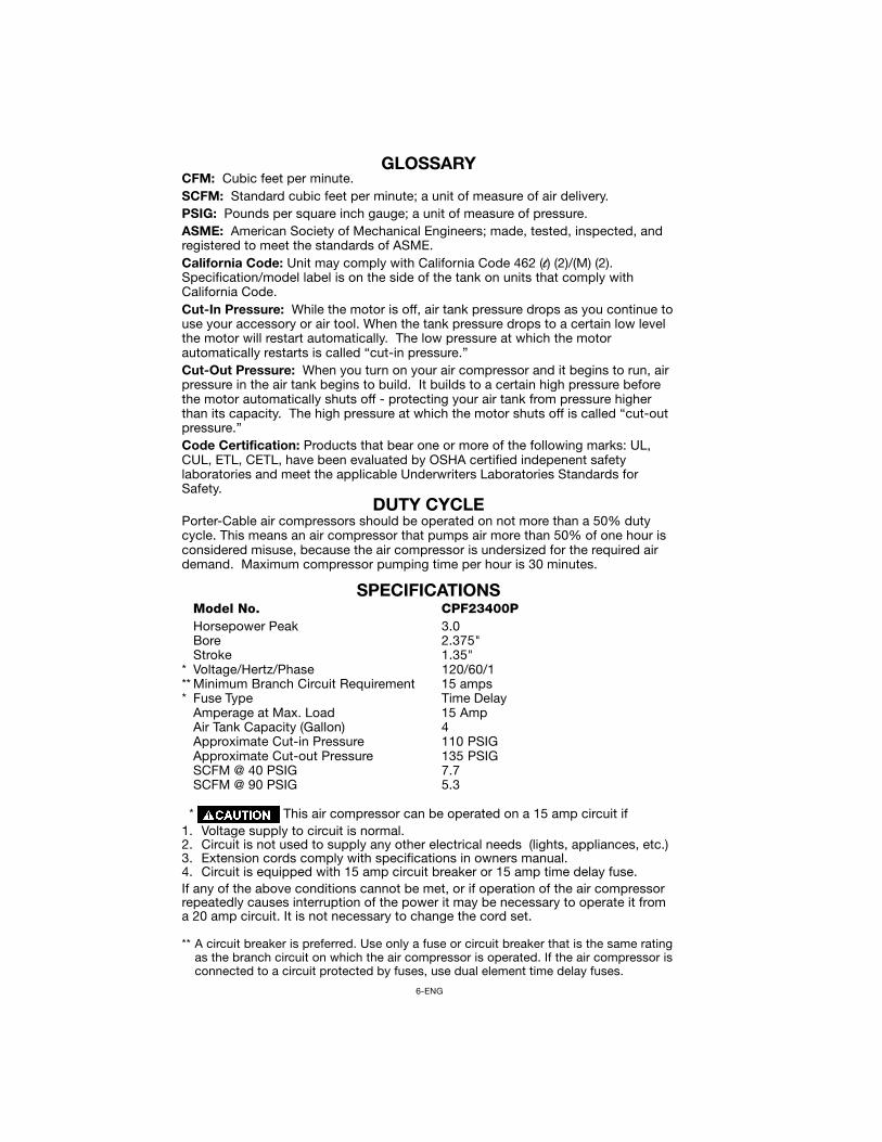
SPECIFICATIONSModel No. CPF23400PHorsepower Peak 3.0Bore 2.375"Stroke 1.35"
* Voltage/Hertz/Phase 120/60/1** Minimum Branch Circuit Requirement 15 amps* Fuse Type Time Delay
Amperage at Max. Load 15 AmpAir Tank Capacity (Gallon) 4Approximate Cut-in Pressure 110 PSIGApproximate Cut-out Pressure 135 PSIGSCFM @ 40 PSIG 7.7SCFM @ 90 PSIG 5.3
* This air compressor can be operated on a 15 amp circuit if1. Voltage supply to circuit is normal.2. Circuit is not used to supply any other electrical needs (lights, appliances, etc.)3. Extension cords comply with specifications in owners manual.4. Circuit is equipped with 15 amp circuit breaker or 15 amp time delay fuse.If any of the above conditions cannot be met, or if operation of the air compressorrepeatedly causes interruption of the power it may be necessary to operate it froma 20 amp circuit. It is not necessary to change the cord set.
** A circuit breaker is preferred. Use only a fuse or circuit breaker that is the same ratingas the branch circuit on which the air compressor is operated. If the air compressor isconnected to a circuit protected by fuses, use dual element time delay fuses.
7-ENG
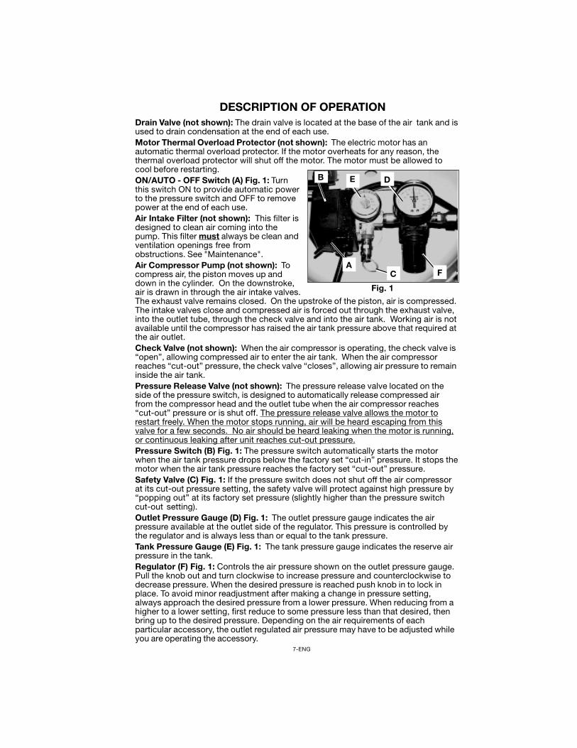
Drain Valve (not shown): The drain valve is located at the base of the air tank and isused to drain condensation at the end of each use.Motor Thermal Overload Protector (not shown): The electric motor has anautomatic thermal overload protector. If the motor overheats for any reason, thethermal overload protector will shut off the motor. The motor must be allowed tocool before restarting.ON/AUTO - OFF Switch (A) Fig. 1: Turnthis switch ON to provide automatic powerto the pressure switch and OFF to removepower at the end of each use.Air Intake Filter (not shown): This filter isdesigned to clean air coming into thepump. This filter must always be clean andventilation openings free fromobstructions. See "Maintenance".Air Compressor Pump (not shown): Tocompress air, the piston moves up anddown in the cylinder. On the downstroke,air is drawn in through the air intake valves.The exhaust valve remains closed. On the upstroke of the piston, air is compressed.The intake valves close and compressed air is forced out through the exhaust valve,into the outlet tube, through the check valve and into the air tank. Working air is notavailable until the compressor has raised the air tank pressure above that required atthe air outlet.Check Valve (not shown): When the air compressor is operating, the check valve is“open”, allowing compressed air to enter the air tank. When the air compressorreaches “cut-out” pressure, the check valve “closes”, allowing air pressure to remaininside the air tank.Pressure Release Valve (not shown): The pressure release valve located on theside of the pressure switch, is designed to automatically release compressed airfrom the compressor head and the outlet tube when the air compressor reaches“cut-out” pressure or is shut off. The pressure release valve allows the motor torestart freely. When the motor stops running, air will be heard escaping from thisvalve for a few seconds. No air should be heard leaking when the motor is running,or continuous leaking after unit reaches cut-out pressure.Pressure Switch (B) Fig. 1: The pressure switch automatically starts the motorwhen the air tank pressure drops below the factory set “cut-in” pressure. It stops themotor when the air tank pressure reaches the factory set “cut-out” pressure.Safety Valve (C) Fig. 1: If the pressure switch does not shut off the air compressorat its cut-out pressure setting, the safety valve will protect against high pressure by“popping out” at its factory set pressure (slightly higher than the pressure switchcut-out setting).Outlet Pressure Gauge (D) Fig. 1: The outlet pressure gauge indicates the airpressure available at the outlet side of the regulator. This pressure is controlled bythe regulator and is always less than or equal to the tank pressure.Tank Pressure Gauge (E) Fig. 1: The tank pressure gauge indicates the reserve airpressure in the tank.Regulator (F) Fig. 1: Controls the air pressure shown on the outlet pressure gauge.Pull the knob out and turn clockwise to increase pressure and counterclockwise todecrease pressure. When the desired pressure is reached push knob in to lock inplace. To avoid minor readjustment after making a change in pressure setting,always approach the desired pressure from a lower pressure. When reducing from ahigher to a lower setting, first reduce to some pressure less than that desired, thenbring up to the desired pressure. Depending on the air requirements of eachparticular accessory, the outlet regulated air pressure may have to be adjusted whileyou are operating the accessory.
DESCRIPTION OF OPERATION
Fig. 1
B
A
E D
FC
8-ENG
Location of the Air CompressorLocate the air compressor in a clean, dry, and well-ventilated area. The air filtermust be kept clear of obstructions which could reduce air flow to the aircompressor. The air compressor should be located at least 12" away from the wallor other obstructions that will interfere with the flow of air. The air compressor headand shroud are designed to allow for proper cooling. If humidity is high, an air filtercan be installed on the air outlet adapter to remove excessive moisture. Follow theinstructions packaged with the air filter for proper installation.
Lubrication and OilThis unit needs no lubrication or oiling.
Extension CordsTo avoid voltage drop, power loss, and overheating to the motor, use extra air hoseinstead of an extension cord. Low voltage can cause damage to the motor.If an extension cord must be used:• use only a 3-wire extension cord that has a 3-blade grounding plug and a 3-slot
receptacle that will accept the plug on the extension cord.• make sure the extension cord is in good condition.• the extension cord should be no longer than 50 feet.• the minimum wire size is 12 gauge (AWG). (Wire size increases as gauge
number decreases. 10 AWG and 8 AWG may also be used. DO NOT USE 14AWG or 16 AWG.)
Voltage and Circuit ProtectionRefer to the specification chart for voltage and circuit protection requirements ofyour compressor. Use only a fuse or circuit breaker that is the same rating as thebranch circuit on which the air compressor is operated. If the compressor isconnected to a circuit protected by fuses, use only dual element time delay fuses.
9-ENG
GROUNDING INSTRUCTIONS
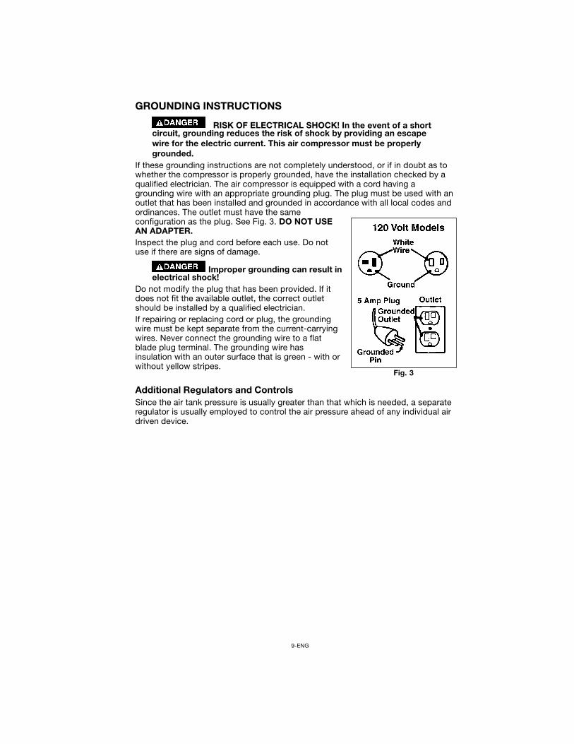
RISK OF ELECTRICAL SHOCK! In the event of a shortcircuit, grounding reduces the risk of shock by providing an escapewire for the electric current. This air compressor must be properlygrounded.
If these grounding instructions are not completely understood, or if in doubt as towhether the compressor is properly grounded, have the installation checked by aqualified electrician. The air compressor is equipped with a cord having agrounding wire with an appropriate grounding plug. The plug must be used with anoutlet that has been installed and grounded in accordance with all local codes andordinances. The outlet must have the sameconfiguration as the plug. See Fig. 3. DO NOT USEAN ADAPTER.Inspect the plug and cord before each use. Do notuse if there are signs of damage.
Improper grounding can result inelectrical shock!
Do not modify the plug that has been provided. If itdoes not fit the available outlet, the correct outletshould be installed by a qualified electrician.If repairing or replacing cord or plug, the groundingwire must be kept separate from the current-carryingwires. Never connect the grounding wire to a flatblade plug terminal. The grounding wire hasinsulation with an outer surface that is green - with orwithout yellow stripes.
Additional Regulators and ControlsSince the air tank pressure is usually greater than that which is needed, a separateregulator is usually employed to control the air pressure ahead of any individual airdriven device.
Fig. 3
10-ENG
OPERATING PROCEDURESDaily Start-Up Checklist1. Before attaching air hose or accessories, make sure the ON/AUTO lever is set to
“OFF” and the air regulator is closed.2. Attach hose and accessories.
TOO MUCH AIR PRESSURE CAUSES A HAZARDOUSRISK OF BURSTING. CHECK THE MANUFACTURER'S MAXIMUMPRESSURE RATING FOR AIR TOOLS AND ACCESSORIES. THEREGULATOR OUTLET PRESSURE MUST NEVER EXCEED THEMAXIMUM PRESSURE RATING.
3. Turn the ON/AUTO lever to “AUTO” and allow tank pressure to build. Motor willstop when tank pressure reaches “cut-out” pressure.
4. Open the regulator by turning it clockwise. Adjust the regulator to the correctpressure setting. Your compressor is ready for use.
5. Always operate the air compressor in well-ventilated areas free of gasoline orother combustible vapors. If the compressoris being used to operate a sprayerDO NOT use near the spray area.
When you are finished:6. Set the “ON/AUTO” lever to “OFF”.7. Turn the regulator counterclockwise and set the outlet pressure to zero.8. Remove the air tool or accessory.9. Pull ring on safety valve allowing air to bleed from the tank until tank pressure is
approximately 20 psi. Release safety valve ring.10.Drain water from air tank by opening drain cock valve on bottom of tank.
WATER WILL CONDENSE IN THE AIR TANK. IF NOTDRAINED, WATER WILL CORRODE AND WEAKEN THE AIR TANKCAUSING A RISK OF AIR TANK RUPTURE.
11.After the water has been drained, close the drain cock or drain valve. The aircompressor can now be stored.
NOTEIf drain cock valve is plugged, release all air pressure. The valve can thenbe removed, cleaned, then reinstalled.
BREAK-IN PROCEDURES
Serious damage may result if the following break-ininstructions are not closely followed.
This procedure is required before the air compressor is put into service. (before thehose is installed), the check valve is replaced, or a complete compressor pump isreplaced.The procedure:1. Make sure the pressure switch lever is in the "OFF" position.2. Plug the power cord into the correct branch circuit receptacle.3. Open the drain valve fully to permit air to escape and prevent air pressure build
up in the air tank during the break-in period.4. Move the pressure switch lever to "ON/AUTO". The compressor will start.5. Run the compressor for 15 minutes. Make sure the drain valve is open and
there is minimal air pressure build-up in tank.6. After 15 minutes, close the drain valve.7. Move the pressure switch lever to "ON/AUTO". The air receiver will fill to cut-
out pressure and the motor will stop. The compressor is now ready for use.
11-ENG
SERVICE INSTRUCTIONSAir Filter - Inspection and Replacement
Keep the air filter clean at all times. Do not operate the compressor with the airfilter removed. A dirty air filter will not allow the compressor to operate at fullcapacity. Before you use the compressor, check the air filter to be sure it is clean.If it is dirty replace it.
Safety Valve - Inspection
IF THE SAFETY VALVE DOES NOT WORK PROPERLY,OVER-PRESSURIZATION MAY OCCUR, CAUSING AIR TANKRUPTURE OR AN EXPLOSION. DAILY PULL THE RING ON THESAFETY VALVE TO MAKE SURE THAT THE SAFETY VALVE OPERATESFREELY. IF THE VALVE IS STUCK OR DOES NOT OPERATESMOOTHLY, IT MUST BE REPLACED WITH THE SAME TYPE OFVALVE.
Check Valve Replacement1. Release all air pressure from air tank and unplug unit.2. Loosen the top and bottom nuts and remove the outlet tube.3. Remove the pressure release tube and fitting.4. Unscrew the check valve using a socket wrench.
MAINTENANCE Unit cycles automatically when power is on. During
maintenance, you could be exposed to voltage sources, compressedair, moving parts, or hot surfaces. Personal injuries can occur. Unplugthe unit and bleed off all air tank pressure and allow unit to coolbefore doing any maintenance or repair. Never operate the unit withthe belt guard removed.
To ensure efficient operation and longer life of the air compressor unit, a routinemaintenance schedule should be prepared and followed. The following routinemaintenance schedule is geared to an unit in a normal working environmentoperating on a daily basis. If necessary, the schedule should be modified to suit theconditions under which your compressor is used. The modifications will dependupon the hours of operation and the working environment. Compressor units in anextremely dirty and/or hostile environment will require a greater frequency of allmaintenance checks.
ROUTINE MAINTENANCE SCHEDULEDaily:1. Pull ring on safety valve allowing air to bleed from the tank until tank pressure is
approximately 20 psi. Release safety valve ring.2. Drain water from the air tank, any moisture separators, or transformers.3. Check for any unusual noise and/or vibration.4. Manually check safety valve to make sure of proper operation.5. Inspect air filter and replace if necessary.6. Inspect air lines and fittings for leaks and correct as necessary.Each Year of Operation or if a Problem is Suspected:Check condition of air compressor pump intake and exhaust valves. Replace ifdamaged or worn out.
12-ENG
5. Check that the valve disc moves freely inside the check valve and that thespring holds the disc in the upper, closed position. The check valve may becleaned with a strong solvent.
6. Apply sealant to the check valve threads. Reinstall the check valve.7. Replace the pressure release tube and fitting.8. Replace the outlet tube and tighten top and bottom nuts.
MotorThe motor has an automatic reset thermal overload protector. If the motoroverheats for any reason, the overload protector will shut off the motor. The motormust be allowed to cool down before restarting. The air compressor willautomatically restart after the motor cools.If the overload protector shuts the motor off frequently, check for a possible voltageproblem. Low voltage can also be suspected when:1. The motor does not get up to full power or speed.2. Fuses blow out when starting the motor; lights dim and remain dim when motor
is started and/or is running.
Motor - Wiring DiagramThe motor connection diagram is located on the side of motor.
STORAGEBefore you store the air compressor, make sure you do the following:1. Review the "Maintenance" section on the preceding pages and perform sched-
uled maintenance as necessary.2. Set the “ON/AUTO” lever to “OFF”.3. Turn the regulator counterclockwise and set the outlet pressure to zero.4. Remove the air tool or accessory.5. Pull ring on safety valve allowing air to bleed from the tank until tank pressure is
approximately 20 psi. Release safety valve ring.6. Drain water from air tank by opening drain cock valve on bottom of tank.
WATER WILL CONDENSE IN THE AIR TANK. IF NOTDRAINED, WATER WILL CORRODE AND WEAKEN THE AIR TANKCAUSING A RISK OF AIR TANK RUPTURE.
7. After the water has been drained, close the drain cock or drain valve.NOTE
If drain cock valve is plugged, release all air pressure. The valve can thenbe removed, cleaned, then reinstalled.
8. Protect the electrical cord and air hose from damage (such as being stepped onor run over). Wind them loosely around the compressor handle. (If so equipped)
Store the air compressor in a clean and dry location.
13-ENG
CAUSE
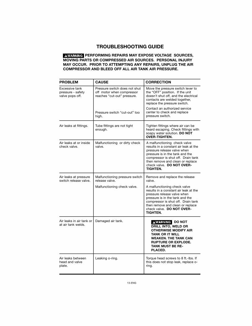
PERFORMING REPAIRS MAY EXPOSE VOLTAGE SOURCES,MOVING PARTS OR COMPRESSED AIR SOURCES. PERSONAL INJURYMAY OCCUR. PRIOR TO ATTEMPTING ANY REPAIRS, UNPLUG THE AIRCOMPRESSOR AND BLEED OFF ALL AIR TANK AIR PRESSURE.
PROBLEM CORRECTION
TROUBLESHOOTING GUIDE
Excessive tankpressure - safetyvalve pops off.
Pressure switch does not shutoff motor when compressorreaches “cut-out” pressure.
Pressure switch “cut-out” toohigh.
Move the pressure switch lever tothe “OFF” position. If the unitdoesn’t shut off, and the electricalcontacts are welded together,replace the pressure switch.
Contact an authorized servicecenter to check and replacepressure switch.
Air leaks at fittings. Tube fittings are not tightenough.
Tighten fittings where air can beheard escaping. Check fittings withsoapy water solution. DO NOTOVER-TIGHTEN.
Air leaks at or insidecheck valve.
Malfunctioning or dirty checkvalve.
A malfunctioning check valveresults in a constant air leak at thepressure release valve whenpressure is in the tank and thecompressor is shut off. Drain tankthen remove and clean or replacecheck valve. DO NOT OVER-TIGHTEN.
Air leaks at pressureswitch release valve.
Malfunctioning pressure switchrelease valve.
Malfunctioning check valve.
Remove and replace the releasevalve.
A malfunctioning check valveresults in a constant air leak at thepressure release valve whenpressure is in the tank and thecompressor is shut off. Drain tankthen remove and clean or replacecheck valve. DO NOT OVER-TIGHTEN.
Damaged air tank. DO NOTDRILL INTO, WELD OROTHERWISE MODIFY AIRTANK OR IT WILLWEAKEN. THE TANK CANRUPTURE OR EXPLODE.TANK MUST BE RE-PLACED.
Air leaks betweenhead and valveplate.
Leaking o-ring. Torque head screws to 8 ft.-lbs. Ifthis does not stop leak, replace o-ring.
Air leaks in air tank orat air tank welds.
14-ENG
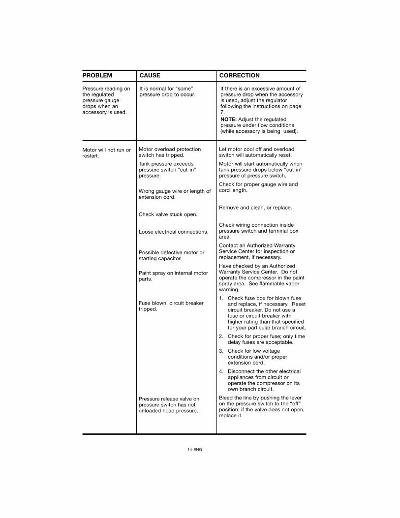
CAUSEPROBLEM CORRECTION
Motor will not run orrestart.
Motor overload protectionswitch has tripped.
Tank pressure exceedspressure switch “cut-in”pressure.
Wrong gauge wire or length ofextension cord.
Check valve stuck open.
Loose electrical connections.
Possible defective motor orstarting capacitor.
Paint spray on internal motorparts.
Fuse blown, circuit breakertripped.
Pressure release valve onpressure switch has notunloaded head pressure.
Let motor cool off and overloadswitch will automatically reset.
Motor will start automatically whentank pressure drops below “cut-in”pressure of pressure switch.
Check for proper gauge wire andcord length.
Remove and clean, or replace.
Check wiring connection insidepressure switch and terminal boxarea.
Contact an Authorized WarrantyService Center for inspection orreplacement, if necessary.
Have checked by an AuthorizedWarranty Service Center. Do notoperate the compressor in the paintspray area. See flammable vaporwarning.
1. Check fuse box for blown fuseand replace, if necessary. Resetcircuit breaker. Do not use afuse or circuit breaker withhigher rating than that specifiedfor your particular branch circuit.
2. Check for proper fuse; only timedelay fuses are acceptable.
3. Check for low voltageconditions and/or properextension cord.
4. Disconnect the other electricalappliances from circuit oroperate the compressor on itsown branch circuit.
Bleed the line by pushing the leveron the pressure switch to the “off”position; if the valve does not open,replace it.
Pressure reading onthe regulatedpressure gaugedrops when anaccessory is used.
It is normal for “some”pressure drop to occur.
If there is an excessive amount ofpressure drop when the accessoryis used, adjust the regulatorfollowing the instructions on page7.NOTE: Adjust the regulatedpressure under flow conditions(while accessory is being used).
15-ENG
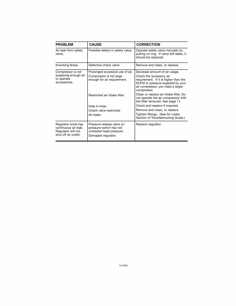
Operate safety valve manually bypulling on ring. If valve still leaks, itshould be replaced.
Possible defect in safety valve.Air leak from safetyvalve.
CAUSEPROBLEM CORRECTION
Knocking Noise. Defective check valve. Remove and clean, or replace.
Compressor is notsupplying enough airto operateaccessories.
Prolonged excessive use of air.Compressor is not largeenough for air requirement.
Restricted air intake filter.
Hole in hose.Check valve restricted.Air leaks.
Decrease amount of air usage.Check the accessory airrequirement. If it is higher than theSCFM or pressure supplied by yourair compressor, you need a largercompressor.Clean or replace air intake filter. Donot operate the air compressor withthe filter removed. See page 11.Check and replace if required.Remove and clean, or replace.Tighten fittings. (See Air LeaksSection of Troubleshooting Guide.)
Regulator knob hascontinuous air leak.Regulator will notshut off air outlet.
Pressure release valve onpressure switch has notunloaded head pressure.Damaged regulator.
Replace regulator.
16-ENG
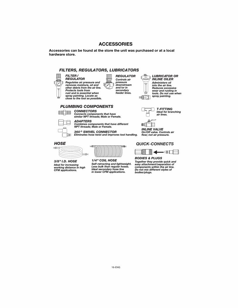
ACCESSORIESAccessories can be found at the store the unit was purchased or at a localhardware store.
PLUMBING COMPONENTSCONNECTORSConnects components that havesimilar NPT threads; Male or Female.
360 O SWIVEL CONNECTOR Eliminates hose twist and improves tool handling.
ADAPTERSCombines components that have different NPT threads; Male or Female.
T-FITTING Ideal for branching air lines.
INLINE VALVE On/Off valve. Controls air flow; not air pressure.
QUICK-CONNECTS
BODIES & PLUGSTogether they provide quick and easy attachment/separation of components within the air line. Do not mix different styles of bodies/plugs.
HOSE
3/8" I.D. HOSEIdeal for increasingworking distance in high CFM applications.
1/4" COIL HOSESelf-retracting and lightweight. Less bulk than regular hoses.Ideal secondary hose linein lower CFM applications.
FILTERS, REGULATORS, LUBRICATORSFILTER /REGULATORRegulates air pressure and removes moisture, oil and other debris from the air line. Protects tools from rust and is essential when spray painting. Locate as close to the tool as possible.
REGULATORControls air pressure downstream and /or in secondary feeder lines.
LUBRICATOR ORINLINE OILERAdministers oil into the air line. Reduces excessive wear and rusting in tools. Do not use when spray painting.

17-ENG
NOTES
LIMITED WARRANTYPORTER-CABLE CORPORATION warrants to the original purchaser that all products covered under thiswarranty are free from defects in material and workmanship. Products covered under this warranty include aircompressors, air tools, service parts, pressure washers, and generators, which have the following warrantyperiods:
3 YEARS - Limited warranty on 2-stage oil-free air compressor pumps that operate at 1725 RPM.2 YEARS - Limited warranty on oil-lubricated air compressor pumps. 1 YEAR - Limited warranty on all other air compressor components.2 YEARS - Limited warranty on electric generator alternators.1 YEAR - Limited warranty on other generator components.2 YEARS - Limited warranty on pneumatic air tools as described in Porter-Cable general catalog.1 YEAR - Limited warranty on pressure washers used in consumer applications (i.e. personal residentialhousehold usage only).90 DAY - Pressure washers used for commercial applications (income producing) and service parts.1 YEAR - Limited warranty on all accessories.
Porter-Cable will repair or replace, at Porter-Cable's option, products or components which have failed with-in the warranty period. Service will be scheduled according to the normal work flow and business hoursat the service center location, and the availability of replacement parts. All decisions of Porter-CableCorporation with regard to this limited warranty shall be final.This warranty gives you specific legal rights, and you may also have other rights which vary from state tostate.RESPONSIBILITY OF ORIGINAL PURCHASER (initial User):• To process a warranty claim on this product, DO NOT return it to the retailer. The product must be evaluat-
ed by an Porter-Cable Authorized Warranty Service Center. For the location of the nearest Porter-CableAuthorized Warranty Service Center call 1-888-559-8550, 24 hours a day, 7 days a week.Retain original cash register sales receipt as proof of purchase for warranty work.Use reasonable care in the operation and maintenance of the product as described in the OwnersManual(s).Deliver or ship the product to the nearest Porter-Cable Authorized Warranty Service Center. Freight costs,if any, must be paid by the purchaser.Air compressors with 60 and 80 gallon tanks will be inspected at the site of installation. Contact the near-est Porter-Cable Authorized Warranty Service Center that provides on-site service calls, for service callarrangements.If the purchaser does not receive satisfactory results from the Porter-Cable Authorized Warranty ServiceCenter, the purchaser should contact Porter-Cable.
THIS WARRANTY DOES NOT COVER:Merchandise sold as reconditioned, used as rental equipment, and floor or display models.Merchandise that has become damaged or inoperative because of ordinary wear, misuse*, cold, heat, rain,excessive humidity, freeze damage, use of improper chemicals, negligence, accident, failure to operatethe product in accordance with the instructions provided in the Owners Manual(s) supplied with the prod-uct, improper maintenance, the use of accessories or attachments not recommended by Porter-Cable, orunauthorized repair or alterations. * An air compressor that pumps air more than 50% during a one hour period is considered misusebecause the air compressor is undersized for the required air demand. Repair and transportation costs of merchandise determined not to be defective.Costs associated with assembly, required oil, adjustments or other installation and start-up costs.Expendable parts or accessories supplied with the product which are expected to become inoperative orunuseable after a reasonable period of use, including but not limited to sanding disks or pads, saw andshear blades, grinding stones, springs, chisels, nozzles, o-rings, air jets, washers and similar accessories.Merchandise sold by Porter-Cable which has been manufactured by and identified as the product ofanother company, such as gasoline engines. The product manufacturer's warranty, if any, will apply. ANY INCIDENTAL, INDIRECT OR CONSEQUENTIAL LOSS, DAMAGE, OR EXPENSE THAT MAYRESULT FROM ANY DEFECT, FAILURE OR MALFUNCTION OF THE PRODUCT IS NOT COVERED BYTHIS WARRANTY. Some states do not allow the exclusion or limitation of incidental or consequentialdamages, so the above limitation or exclusion may not apply to you.IMPLIED WARRANTIES, INCLUDING THOSE OF MERCHANTABILITY OR FITNESS FOR A PARTICU-LAR PURPOSE, ARE LIMITED TO ONE YEAR FROM THE DATE OF ORIGINAL PURCHASE. Somestates do not allow limitations on how long an implied warranty lasts, so the above limitations may notapply to you.
Porter-Cable CorporationJackson, TN USA1-888-559-8550
•
•
•
•
••
•
•••
•
•
•