Embed Size (px)
Citation preview

INS
TRU
CTIO
NM
AN
UA
LDC-580 20" Planer
(Model 22-450, Three Phase)(Model 22-451, Single Phase)
PART NO. 1349960 - 06-02-05Copyright © 2005 Delta Machinery
To learn more about DELTA MACHINERY visit our website at: www.deltamachinery.com.For Parts, Service, Warranty or other Assistance,
please call 1-800-223-7278 (In Canada call 1-800-463-3582).

2
TABLE OF CONTENTS
Read and understand all warnings and operating instructions before using any tool or equipment. Whenusing tools or equipment, basic safety precautions should always be followed to reduce the risk of personal injury.Improper operation, maintenance or modification of tools or equipment could result in serious injury and propertydamage. There are certain applications for which tools and equipment are designed. Delta Machinery stronglyrecommends that this product NOT be modified and/or used for any application other than for which it was designed.
If you have any questions relative to its application DO NOT use the product until you have written Delta Machineryand we have advised you.
Online contact form at www.deltamachinery.com
Postal Mail: Technical Service ManagerDelta Machinery4825 Highway 45 NorthJackson, TN 38305(IN CANADA: 125 Mural St. Suite 300, Richmond Hill, ON, L4B 1M4)
Information regarding the safe and proper operation of this tool is available from the following sources:
Power Tool Institute1300 Sumner Avenue, Cleveland, OH 44115-2851www.powertoolinstitute.org
National Safety Council1121 Spring Lake Drive, Itasca, IL 60143-3201
American National Standards Institute, 25 West 43rd Street, 4 floor, New York, NY 10036 www.ansi.orgANSI 01.1Safety Requirements for Woodworking Machines, and
the U.S. Department of Labor regulations www.osha.gov
IMPORTANT SAFETY INSTRUCTIONS
SAVE THESE INSTRUCTIONS!
IMPORTANT SAFETY INSTRUCTIONS . . . . . . . . . . . . . . . . . . . . . . . . . . . . . . . . . . . . . . . . . . . . . . . . . . . . . . . . . . .2SAFETY GUIDELINES . . . . . . . . . . . . . . . . . . . . . . . . . . . . . . . . . . . . . . . . . . . . . . . . . . . . . . . . . . . . . . . . . . . . . . . .3GENERAL SAFETY RULES . . . . . . . . . . . . . . . . . . . . . . . . . . . . . . . . . . . . . . . . . . . . . . . . . . . . . . . . . . . . . . . . . . . .4ADDITIONAL SPECIFIC SAFETY RULES . . . . . . . . . . . . . . . . . . . . . . . . . . . . . . . . . . . . . . . . . . . . . . . . . . . . . . . . .5FUNCTIONAL DESCRIPTION . . . . . . . . . . . . . . . . . . . . . . . . . . . . . . . . . . . . . . . . . . . . . . . . . . . . . . . . . . . . . . . . . .6CARTON CONTENTS . . . . . . . . . . . . . . . . . . . . . . . . . . . . . . . . . . . . . . . . . . . . . . . . . . . . . . . . . . . . . . . . . . . . . . . . .7ASSEMBLY . . . . . . . . . . . . . . . . . . . . . . . . . . . . . . . . . . . . . . . . . . . . . . . . . . . . . . . . . . . . . . . . . . . . . . . . . . . . . . . . .7OPERATION . . . . . . . . . . . . . . . . . . . . . . . . . . . . . . . . . . . . . . . . . . . . . . . . . . . . . . . . . . . . . . . . . . . . . . . . . . . . . . .11TROUBLESHOOTING . . . . . . . . . . . . . . . . . . . . . . . . . . . . . . . . . . . . . . . . . . . . . . . . . . . . . . . . . . . . . . . . . . . . . . .22MAINTENANCE . . . . . . . . . . . . . . . . . . . . . . . . . . . . . . . . . . . . . . . . . . . . . . . . . . . . . . . . . . . . . . . . . . . . . . . . . . . . .22SERVICE . . . . . . . . . . . . . . . . . . . . . . . . . . . . . . . . . . . . . . . . . . . . . . . . . . . . . . . . . . . . . . . . . . . . . . . . . . . . . . . . . .23ACCESSORIES . . . . . . . . . . . . . . . . . . . . . . . . . . . . . . . . . . . . . . . . . . . . . . . . . . . . . . . . . . . . . . . . . . . . . . . . . . . .23WARRANTY . . . . . . . . . . . . . . . . . . . . . . . . . . . . . . . . . . . . . . . . . . . . . . . . . . . . . . . . . . . . . . . . . . . . . . . . . . . . . . . .23SERVICE CENTER LOCATIONS . . . . . . . . . . . . . . . . . . . . . . . . . . . . . . . . . . . . . . . . . . . . . . . . . . . . . . . .back cover

3
Indicates an imminently hazardous situation which, if not avoided, will result in death or serious injury.
Indicates a potentially hazardous situation which, if not avoided, could result in death or serious injury.
Indicates a potentially hazardous situation which, if not avoided, may result in minor or moderate injury.
Used without the safety alert symbol indicates potentially hazardous situation which, if not avoided, mayresult in property damage.
It is important for you to read and understand this manual. The information it contains relates to protectingYOUR SAFETY and PREVENTING PROBLEMS. The symbols below are used to help you recognize thisinformation.
SAFETY GUIDELINES - DEFINITIONS
SOME DUST CREATED BY POWER SANDING, SAWING, GRINDING, DRILLING, AND OTHERCONSTRUCTION ACTIVITIES contains chemicals known to cause cancer, birth defects or other reproductive harm.Some examples of these chemicals are:· lead from lead-based paints,· crystalline silica from bricks and cement and other masonry products, and· arsenic and chromium from chemically-treated lumber. Your risk from these exposures varies, depending on how often you do this type of work. To reduce your exposure tothese chemicals: work in a well ventilated area, and work with approved safety equipment, always wear NIOSH/OSHAapproved, properly fitting face mask or respirator when using such tools.
CALIFORNIA PROPOSITION 65
4
GENERAL SAFETY RULES
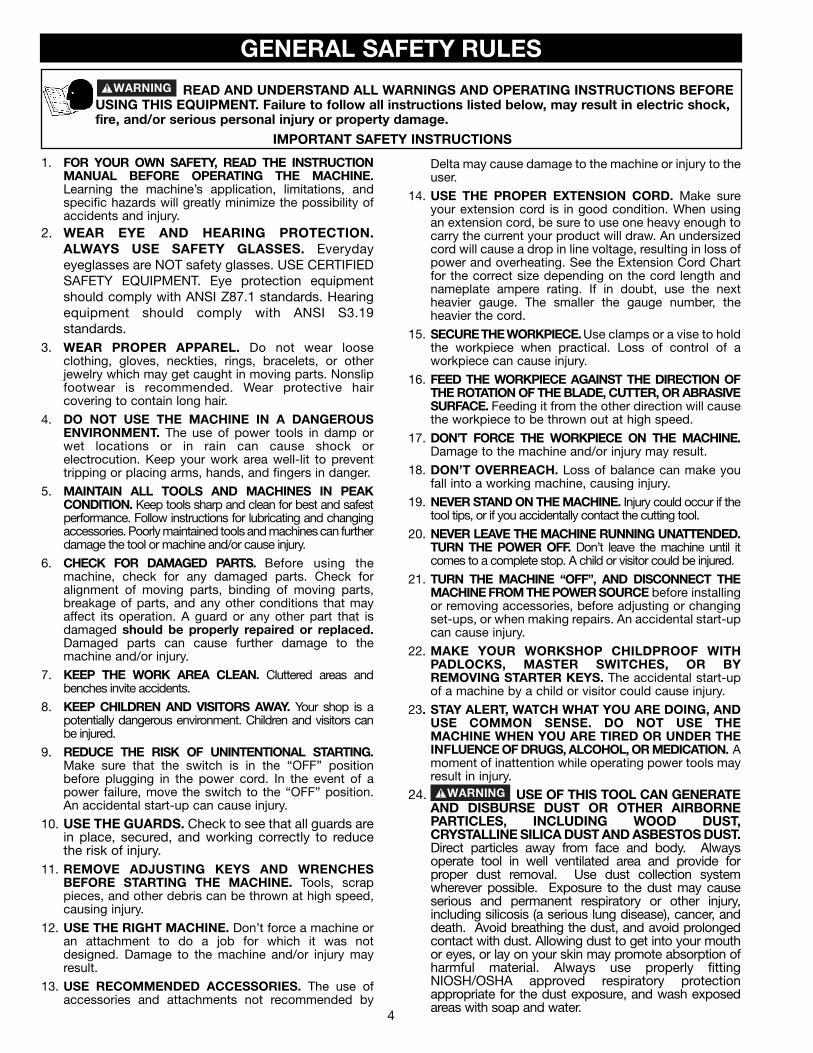
READ AND UNDERSTAND ALL WARNINGS AND OPERATING INSTRUCTIONS BEFOREUSING THIS EQUIPMENT. Failure to follow all instructions listed below, may result in electric shock,fire, and/or serious personal injury or property damage.
IMPORTANT SAFETY INSTRUCTIONS
1. FOR YOUR OWN SAFETY, READ THE INSTRUCTIONMANUAL BEFORE OPERATING THE MACHINE.Learning the machine’s application, limitations, andspecific hazards will greatly minimize the possibility ofaccidents and injury.
2. WEAR EYE AND HEARING PROTECTION.ALWAYS USE SAFETY GLASSES. Everydayeyeglasses are NOT safety glasses. USE CERTIFIEDSAFETY EQUIPMENT. Eye protection equipmentshould comply with ANSI Z87.1 standards. Hearingequipment should comply with ANSI S3.19standards.
3. WEAR PROPER APPAREL. Do not wear looseclothing, gloves, neckties, rings, bracelets, or otherjewelry which may get caught in moving parts. Nonslipfootwear is recommended. Wear protective haircovering to contain long hair.
4. DO NOT USE THE MACHINE IN A DANGEROUSENVIRONMENT. The use of power tools in damp orwet locations or in rain can cause shock orelectrocution. Keep your work area well-lit to preventtripping or placing arms, hands, and fingers in danger.
5. MAINTAIN ALL TOOLS AND MACHINES IN PEAKCONDITION. Keep tools sharp and clean for best and safestperformance. Follow instructions for lubricating and changingaccessories. Poorly maintained tools and machines can furtherdamage the tool or machine and/or cause injury.
6. CHECK FOR DAMAGED PARTS. Before using themachine, check for any damaged parts. Check foralignment of moving parts, binding of moving parts,breakage of parts, and any other conditions that mayaffect its operation. A guard or any other part that isdamaged should be properly repaired or replaced.Damaged parts can cause further damage to themachine and/or injury.
7. KEEP THE WORK AREA CLEAN. Cluttered areas andbenches invite accidents.
8. KEEP CHILDREN AND VISITORS AWAY. Your shop is apotentially dangerous environment. Children and visitors canbe injured.
9. REDUCE THE RISK OF UNINTENTIONAL STARTING.Make sure that the switch is in the “OFF” positionbefore plugging in the power cord. In the event of apower failure, move the switch to the “OFF” position.An accidental start-up can cause injury.
10. USE THE GUARDS. Check to see that all guards arein place, secured, and working correctly to reducethe risk of injury.
11. REMOVE ADJUSTING KEYS AND WRENCHESBEFORE STARTING THE MACHINE. Tools, scrappieces, and other debris can be thrown at high speed,causing injury.
12. USE THE RIGHT MACHINE. Don’t force a machine oran attachment to do a job for which it was notdesigned. Damage to the machine and/or injury mayresult.
13. USE RECOMMENDED ACCESSORIES. The use ofaccessories and attachments not recommended by
Delta may cause damage to the machine or injury to theuser.
14. USE THE PROPER EXTENSION CORD. Make sureyour extension cord is in good condition. When usingan extension cord, be sure to use one heavy enough tocarry the current your product will draw. An undersizedcord will cause a drop in line voltage, resulting in loss ofpower and overheating. See the Extension Cord Chartfor the correct size depending on the cord length andnameplate ampere rating. If in doubt, use the nextheavier gauge. The smaller the gauge number, theheavier the cord.
15. SECURE THE WORKPIECE. Use clamps or a vise to holdthe workpiece when practical. Loss of control of aworkpiece can cause injury.
16. FEED THE WORKPIECE AGAINST THE DIRECTION OFTHE ROTATION OF THE BLADE, CUTTER, OR ABRASIVESURFACE. Feeding it from the other direction will causethe workpiece to be thrown out at high speed.
17. DON’T FORCE THE WORKPIECE ON THE MACHINE.Damage to the machine and/or injury may result.
18. DON’T OVERREACH. Loss of balance can make youfall into a working machine, causing injury.
19. NEVER STAND ON THE MACHINE. Injury could occur if thetool tips, or if you accidentally contact the cutting tool.
20. NEVER LEAVE THE MACHINE RUNNING UNATTENDED.TURN THE POWER OFF. Don’t leave the machine until itcomes to a complete stop. A child or visitor could be injured.
21. TURN THE MACHINE “OFF”, AND DISCONNECT THEMACHINE FROM THE POWER SOURCE before installingor removing accessories, before adjusting or changingset-ups, or when making repairs. An accidental start-upcan cause injury.
22. MAKE YOUR WORKSHOP CHILDPROOF WITHPADLOCKS, MASTER SWITCHES, OR BYREMOVING STARTER KEYS. The accidental start-upof a machine by a child or visitor could cause injury.
23. STAY ALERT, WATCH WHAT YOU ARE DOING, ANDUSE COMMON SENSE. DO NOT USE THEMACHINE WHEN YOU ARE TIRED OR UNDER THEINFLUENCE OF DRUGS, ALCOHOL, OR MEDICATION. Amoment of inattention while operating power tools mayresult in injury.
24. USE OF THIS TOOL CAN GENERATEAND DISBURSE DUST OR OTHER AIRBORNEPARTICLES, INCLUDING WOOD DUST,CRYSTALLINE SILICA DUST AND ASBESTOS DUST.Direct particles away from face and body. Alwaysoperate tool in well ventilated area and provide forproper dust removal. Use dust collection systemwherever possible. Exposure to the dust may causeserious and permanent respiratory or other injury,including silicosis (a serious lung disease), cancer, anddeath. Avoid breathing the dust, and avoid prolongedcontact with dust. Allowing dust to get into your mouthor eyes, or lay on your skin may promote absorption ofharmful material. Always use properly fittingNIOSH/OSHA approved respiratory protectionappropriate for the dust exposure, and wash exposedareas with soap and water.

ADDITIONAL SPECIFIC SAFETY RULES
SAVE THESE INSTRUCTIONS. Refer to them often and use them to instruct others.
1. DO NOT OPERATE THIS MACHINE until it iscompletely assembled and installed according tothe instructions. A machine incorrectly assembledcan cause serious injury.
2. OBTAIN ADVICE from your supervisor, instructor,or another qualified person if you are notthoroughly familiar with the operation of thismachine. Knowledge is safety.
3. FOLLOW ALL WIRING CODES and recommend-ed electrical connections to prevent shock orelectrocution.
4. KEEP KNIVES SHARP and free from rust andpitch. Dull or rusted knives work harder and cancause kickback.
5. NEVER TURN THE MACHINE “ON” before clearingthe table of all objects (tools, scraps of wood, etc.).Flying debris can cause serious injury.
6. NEVER TURN THE MACHINE “ON” with the work-piece contacting the cutterhead. Kickback canoccur.
7. SECURE THE MACHINE TO A SUPPORTING SUR-FACE to prevent the machine from sliding, walkingor tipping over.
8. PROPERLY SECURE THE KNIVES IN THE CUTTER-HEAD before turning the power “ON”. Looseblades may be thrown out at high speeds causingserious injury.
9. LOCK THE SPEED SETTING SECURELY beforefeeding the workpiece through the machine.Changing speeds while planing can cause kick-back.
10. AVOID AWKWARD OPERATIONS AND HAND POSI-TIONS. A sudden slip could cause a hand to moveinto the knives.
11. KEEP ARMS, HANDS, AND FINGERS away fromthe cutterhead, the chip exhaust opening, and thefeed rollers to prevent severe cuts.
12. NEVER REACH INTO THE CUTTERHEAD AREAwhile the machine is running. Your hands can bedrawn into the knives.
13. DO NOT STAND IN LINE OF THE WORKPIECE.Kickback can cause injury.
14. ALLOW THE CUTTERHEAD TO REACH FULL SPEEDbefore feeding a workpiece. Changing speedswhile planing can cause kickback.
15. WHEN PLANING BOWED STOCK, place the concave(cup down) side of the stock on the table and cutwith the grain to prevent kickback.
16. DO NOT FEED A WORKPIECE that is warped,contains knots, or is embedded with foreignobjects (nails, staples, etc.). Kickback can occur.
17. DO NOT FEED A SHORT, THIN, OR NARROWWORKPIECE INTO THE MACHINE. Your hands canbe drawn into the knives and/or the workpiece canbe thrown at high speeds. See the “OPERATION”section of this instruction manual for details.
18. DO NOT FEED A WORKPIECE into the outfeed end ofthe machine. The workpiece will be thrown out ofthe opposite side at high speeds.
19. REMOVE SHAVINGS ONLY with the power “OFF” toprevent serious injury.
20. PROPERLY SUPPORT LONG OR WIDE WORK-PIECES. Loss of control of the workpiece can causeserious injury.
21. NEVER PERFORM LAYOUT, ASSEMBLY or set-upwork on the table/work area when the machine isrunning. Serious injury will result.
22. TURN THE MACHINE “OFF”, DISCONNECT IT FROMTHE POWER SOURCE, and clean the table/workarea before leaving the machine. LOCK THESWITCH IN THE “OFF” POSITION to prevent un-authorized use. Someone else might accidentallystart the machine and cause injury to themselvesor others.
23. ADDITIONAL INFORMATION regarding the safeand proper operation of power tools (i.e. a safetyvideo) is available from the Power Tool Institute,1300 Sumner Avenue, Cleveland, OH 44115-2851(www.powertoolinstitute.com). Information is alsoavailable from the National Safety Council, 1121Spring Lake Drive, Itasca, IL 60143-3201. Pleaserefer to the American National Standards InstituteANSI 01.1 Safety Requirements for WoodworkingMachines and the U.S. Department of LaborRegulations.
FAILURE TO FOLLOW THESE RULES MAY RESULT IN SERIOUS INJURY.
5

66
FOREWORDFUNCTIONAL DESCRIPTION
NOTICE: THE PHOTO ON THE MANUAL COVER ILLUSTRATES THE CURRENT PRODUCTIONMODEL. ALL OTHER ILLUSTRATIONS CONTAINED IN THE MANUAL ARE REPRESENTATIVE ONLYAND MAY NOT DEPICT THE ACTUAL COLOR, LABELING OR ACCESSORIES AND ARE INTENDEDTO ILLUSTRATE TECHNIQUE ONLY.
The Delta Indusrial Model 22-450 (DC-580) 20" Planer has a 3-phase, 5HP motor with an LVC magnetic starter andautomatic reset overload protection; 3-knife cutterhead, sectional serrated infeed roll, double bed rollers andpolyurethane outfeed roller, sectional chipbreakers, dust chute, knife-setting gage, and wrench. The Delta IndustrialModel 22-451 (DC-580) 20" Planer is the same as above except with a single-phase, 5HP motor.
THIS MACHINE MUST BE GROUNDED WHILE IN USE TO PROTECT THE OPERATOR FROMELECTRIC SHOCK.
GROUNDING INSTRUCTIONS
These machines are not supplied with power cords and they are intended to be permanently connected to the building’selecrical system. All wiring must be done by a qualified electrician and conform to the National Electric Code and all local codesand ordinances. For wiring instructions, see section “ELECTRICAL CONNECTIONS” in this manual.
LVC MAGNETIC MOTOR CONTROL: If you purchased a machine that has a Low Voltage Magnetic Motor Control System,refer to its instruction manual for installation guidance.
MOTOR SPECIFICATIONSYour machine has a 5HP motor that is wired at 220 volts and 60 HZ alternating current. It may be wired for threephase or single phase operation - check the spec plate on the motor.
A separate electrical circuit should be used for your machines. This circuit should not be less than #12 wire and should beprotected with a 20 Amp time lag fuse. Before connecting the machine to the power line, make sure the switch (s) is in the“OFF” position and be sure that the electric current is of the same characteristics as indicated on the machine. All lineconnections should make good contact. Running on low voltage will damage the machine.
DO NOT EXPOSE THE MACHINE TO RAIN OR OPERATE THE MACHINE IN DAMP LOCATIONS.
POWER CONNECTIONS

77
UNPACKING AND CLEANINGCarefully unpack the machine and all loose items from the shipping container(s). Remove the protective coating fromall unpainted surfaces. This coating may be removed with a soft cloth moistened with kerosene (do not use acetone,gasoline or lacquer thinner for this purpose). After cleaning, cover the unpainted surfaces with a good quality householdfloor paste wax.
CARTON CONTENTSThe DC-580, 20" planer is shipped complete in one container mounted to a shipping skid. Remove the wooden crate from aroundthe machine. The planer is shipped with the motor, motor pulleys and belts assembled to the machine. Fig. 2, illustrates the looseitems supplied with the machine.
A
B
C
D
E
F
GH
Fig. 2
A. Cutterhead Guard
B. Dust Hood
C. M6 x 1 x 12mm Button Head Screws for fastening the cover and dust hood to the machine (13)
D. Knife setting gage
E. Handwheel handle
F. 4mm T-handle wrench
G. M6 Allen wrench
H. 10 x 14mm open end wrench
ASSEMBLYASSEMBLY TOOLS REQUIRED
ASSEMBLY TIME ESTIMATE - 1-2 hours
* M6 Allen wrench (supplied)* Flathead Screwdriver (Not Supplied* Forklift and Lifting Straps For Set-Up (Not Supplied)

8
Fig. 4
Fig. 5
Fig. 6
UNPACKING AND CLEANING
Remove the bolts that fasten the machine to theshipping skid.
Two lifting lugs are built into the machine, one of whichis shown at (E) Fig. 3. These lugs can be used tomechanically lift the machine using a forklift and liftingstraps. NOTE: The other lifting lug is located at the rearand the opposite end of the machine. Carefully removethe planer from the shipping skid.
Thread handle assembly (A) Fig. 3, into handwheel (B)and tighten locknut (C).
If it is necessary to lower the table (B) Fig. 4, to facilitatecleaning, loosen lock knob (C) and turn handwheel (D)counterclockwise until the table (B) is at the desiredheight for cleaning.
With allen wrench supplied, loosen and remove screw(E) Fig. 5, from the left top edge of the machine and raisethe top cover (F) Fig. 6 as shown, exposing thechipbreakers, and cutterhead. NOTE: The top cover ofthe machine is hinged to facilitate cleaning andperforming maintenance and adjustment procedures.
Carefully remove the protective coating from the table,table rollers, infeed roller, anti-kickback fingers,cutterhead and cutterhead knives. This protectivecoating may be removed with a soft cloth moistenedwith kerosene. (DO NOT USE GASOLINE, ACETONE,OR LACQUER THINNER FOR THIS PURPOSE).CAUTION: Extreme care should be taken whencleaning the knives as the cutterhead knives arepositioned in the cutterhead and are very sharp.
After cleaning, cover the table surface with a goodquality paste wax.
Lower top cover and replace locking screw which wasremoved in STEP 5.
B
D
C
E
F
Fig. 3
CA
B
E

9
ASSEMBLING CUTTERHEAD GUARD
Position cutterhead guard (A) Fig. 7, on top cover ofmachine. Align holes in cutterhead guard (A) Fig. 7, withholes in top cover and fasten with six M6x12mm buttonhead screws (B), five of which are shown.
Fig. 7ASSEMBLING DUST HOOD
A dust hood with a 5" opening is supplied with yourmachine and is to be used when connecting the planerto a dust collector or a central dust collection system.
Position dust hood (A) Fig. 8, against the rear of themachine and on top of cutterhead guard (B). Align theholes and fasten the dust hood (A) Fig. 9, to thecutterhead guard (B) using seven M6x12mm buttonhead screws (C), four of which are shown.
Fig. 8
Fig. 9
AB
AB
A
C
B
10
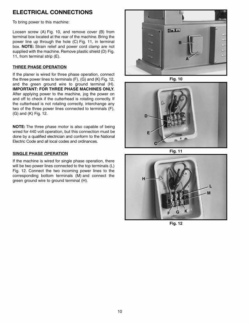
To bring power to this machine:
Loosen screw (A) Fig. 10, and remove cover (B) fromterminal box located at the rear of the machine. Bring thepower line up through the hole (C) Fig. 11, in terminalbox. NOTE: Strain relief and power cord clamp are notsupplied with the machine. Remove plastic shield (D) Fig.11, from terminal strip (E).
Fig. 12
Fig. 11
Fig. 10
THREE PHASE OPERATION
If the planer is wired for three phase operation, connectthe three power lines to terminals (F), (G) and (K) Fig. 12,and the green ground wire to ground terminal (H).IMPORTANT: FOR THREE PHASE MACHINES ONLY.After applying power to the machine, jog the power onand off to check if the cutterhead is rotating correctly. Ifthe cutterhead is not rotating correctly, interchange anytwo of the three power lines connected to terminals (F),(G) and (K) Fig. 12.
NOTE: The three phase motor is also capable of beingwired for 440 volt operation, but this connection must bedone by a qualified electrician and conform to the NationalElectric Code and all local codes and ordinances.
SINGLE PHASE OPERATION
If the machine is wired for single phase operation, therewill be two power lines connected to the top terminals (L)Fig. 12. Connect the two incoming power lines to thecorresponding bottom terminals (M) and connect thegreen ground wire to ground terminal (H).
B
A
D
E
C
GF K
H
M
L
ELECTRICAL CONNECTIONS
11
Fig. 13
Fig. 14
RAISING AND LOWERING TABLE
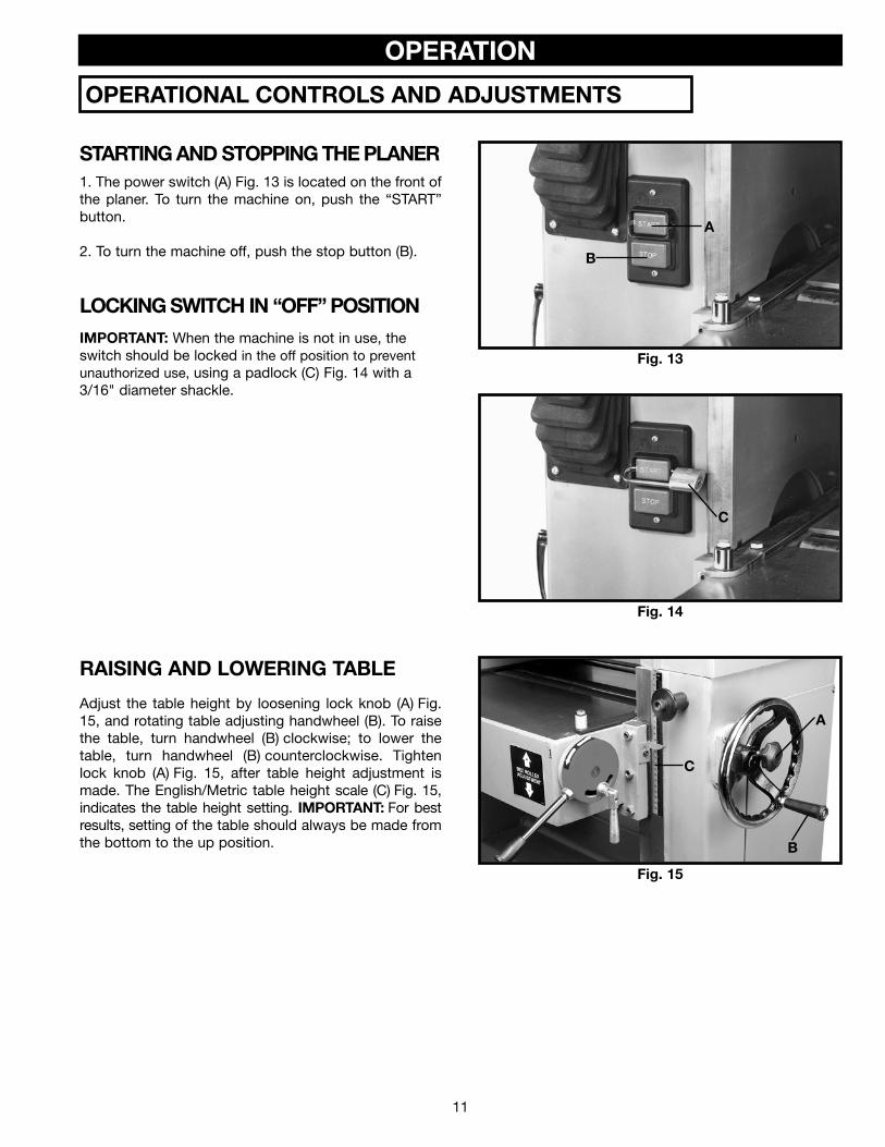
Adjust the table height by loosening lock knob (A) Fig.15, and rotating table adjusting handwheel (B). To raisethe table, turn handwheel (B) clockwise; to lower thetable, turn handwheel (B) counterclockwise. Tightenlock knob (A) Fig. 15, after table height adjustment ismade. The English/Metric table height scale (C) Fig. 15,indicates the table height setting. IMPORTANT: For bestresults, setting of the table should always be made fromthe bottom to the up position.
Fig. 15
A
B
C
C
A
B
OPERATION
OPERATIONAL CONTROLS AND ADJUSTMENTS
STARTING AND STOPPING THE PLANER1. The power switch (A) Fig. 13 is located on the front ofthe planer. To turn the machine on, push the “START”button.
2. To turn the machine off, push the stop button (B).
LOCKING SWITCH IN “OFF” POSITION
IMPORTANT: When the machine is not in use, theswitch should be locked in the off position to preventunauthorized use, using a padlock (C) Fig. 14 with a3/16" diameter shackle.

12
Fig. 17Fig. 16
Fig. 19Fig. 20
Fig. 18
FEED ROLLER SPEEDSYour planer is equipped with feed roller speeds of 20and 30 feet per minute depending on belt placementon the pulleys. As a rule, a faster feed rate is used forgeneral planing operations, while a slower feed rate(because it provides more cuts per inch of stock) givesa finer and smoother finish to the workpiece.
1. To engage the feed rollers, simultaneously pushbutton (A) Fig. 16, and pull downward on handle (B).2. To disengage the feed rollers, simultaneously pushbutton (A) Fig. 17, and move handle (B) to the raisedposition, as shown.3. To change feed roller speeds, disengage the feedrollers as explained in STEP 2.4. DISCONNECT MACHINE FROMPOWER SOURCE.5. Open two doors (C) and (D) Fig. 18, located on theleft side of the machine.6. Reposition drive belt (E) Fig. 19, on pulleys (F) and(G). When belt (E) Fig. 19, is on the smallest step ofmotor pulley (G) and the largest step of the gear boxpulley (F), the feed roller speed will be 20 feet perminute. When belt (E) Fig. 19, is on the largest step ofthe motor pulley (G) and the smallest step of gear boxpulley (F), the feed roller speed will be 30 feet perminute. A feed rate adjustment chart is located on theback of panel (C) Fig. 20, for quick reference.
A
B
A
B
C
D
F
E
G
C

13
TABLE ROLLERSYour planer is supplied with two table rollers (A) Fig. 21,which aid in feeding the stock by reducing friction be-tween the stock and the table and rotate as the stockis fed through the planer.
1. To raise the table rollers, loosen locking lever (B) Fig.21, and pull control lever (C) upward to the desiredheight setting.
2. To lower the table rollers, loosen locking lever (B) Fig.21, and push control lever (C) downward to the desiredheight setting.
3. After adjusting height of the table rollers, tightenlocking lever (B) Fig. 21.
Fig. 21
CHECKING AND ADJUSTING TABLEROLLER HEIGHT
It is not possible to give exact dimensions on the properheight setting of the table rollers because each type ofwood has different behavioral patterns. As a generalrule, when planing rough stock, the table rollers shouldbe set high (.003" to .005") above the table surface.When planing finish stock, the table rollers should be setlow (.001") above or level with the table surface.To check and adjust the height of the table rollers,proceed as follows: Fig. 22
Fig. 23
Fig. 24
1. DISCONNECT MACHINE FROMPOWER SOURCE.
2. With the table rollers in the lowest position, lay astraight edge (A) Fig. 22, across both table rollers (B) onthe left side of the table as shown.
3. With a feeler gage (B) Fig. 23, measure the gapbetween the table surface and the straight edge (A) nearthe infeed roller (C).
4. If an adjustment to the infeed table roller is necessary,loosen locknut (D) Fig. 24, which is located under the tableand below the infeed roller and rotate adjustment nuts (E)as necessary to raise or lower the height of the infeedroller. NOTE: It will be necessary to raise the table to gainaccess to the adjustment nuts. Tighten locknut (D) afteradjustment is made.
5. Check and adjust the height of the infeed table rolleron the other side of the table in the same manner.
A
B
C
AB
C B
A
D
E

14
Fig. 25
6. To check the height of the outfeed table roller, proceedas follows: with a feeler gage (B) Fig. 25, measure the gapbetween the table surface and the straight edge (A) nearthe outfeed roller (F).
Fig. 26
7. If an adjustment to the outfeed table roller isnecessary, loosen locknut (G) Fig. 26, which is locatedunder the table and below the outfeed table roller (F), androtate adjustment nuts (H) as necessary, to raise or lowerthe height of the outfeed roller (F). NOTE: It will benecessary to raise the table to gain access to theadjustment nuts. Tighten locknut (G) Fig. 26, after theadjustment is made.
8. Check and adjust the height of the outfeed table rolleron the other side of the table in the same manner.
ANTI-KICKBACK FINGERSA series of anti-kickback fingers (A) Fig. 27, are providedon the infeed end of the planer to prevent kickback of theworkpiece during planing operations. These anti-kickbackfingers operate by gravity and no adjustment is required. Itis necessary, however, to inspect them occasionally tomake sure they are free of gum and pitch and that theyoperate independently and freely.
WHEN INSPECTING AND CLEANINGTHE ANTI-KICKBACK FINGERS, MAKE CERTAINTHE MACHINE IS DISCONNECTED FROM THEPOWER SOURCE. Fig. 27
B AF
FG
H
A

15
CHECKING AND ADJUSTING DRIVE BELT TENSIONProper belt tension is when there is approximately 1/4" deflection, using light finger pressure on the drive belts (A) Fig.28, midway between pulleys. If an adjustment is necessary, proceed as follows:
Fig. 28
1. DISCONNECT MACHINE FROMPOWER SOURCE.
2. Disengage feed roller lever (B) Fig. 28.
3. Loosen and tighten two adjustment nuts (C) Fig. 29, tomove motor plate up or down as necessary to increase ordecrease drive belt tension.Tighten both adjustment nuts(C) against plate (D) Fig. 29, after adjustment is made.
4. Close both side panels.
Fig. 29
AB
C
D

16
Fig. 30
CHECKING AND ADJUSTING FEED ROLLER BELT TENSIONProper tension on the feed roller belt is obtained when there is approximately 1/2" deflection, using light finger pressureon feed roller belt (A) Fig. 30. midway between pulleys (B) and (C), with feed roller lever (D) engaged. If an adjustment isnecessary, proceed as follows:
1. DISCONNECT MACHINE FROMPOWER SOURCE.
2. Engage feed roller lever (D) Fig. 30.
3. Remove four screws (E) Fig. 31, which holdengagement lever boot (F) to the machine.
4. Raise boot (F) Fig. 32, to gain access to adjustmenthardware.
5. Loosen jam nut (G) Fig. 32, and tighten or loosen ad-justment hex nut (H) as necessary to adjust feed roller belttension.
6. Tighten jam nut (G) Fig. 32, against hex nut (H) afteradjustment is made.
7. Replace the engagement lever boot (F) Fig. 32.
Fig. 31
Fig. 32
B
C
A
E
E
F
H
G

Fig. 33
Fig. 34
Fig. 35
CHECKING, RESETTINGAND REPLACING KNIVES
When checking, resetting and replacing knives, proceedas follows:
1. DISCONNECT MACHINE FROMPOWER SOURCE.
2. Remove locking screw (E) Fig. 4, and raise top cover(A) Fig. 33, to expose cutterhead (B).
3. Carefully place knife setting gage (C) Figs. 34 and 35,so the gage is positioned on the radiused section ofcutterhead (B). When set correctly, knife (D) Figs. 34 and35, should just contact the bottom of inset section (E) Fig.35 of knife setting gage (C) which is set at .070". Check theremaining knives in the same manner.
4. If an adjustment to one or all three knives is necessary,slightly loosen the ten locking screws, one of which isshown at (F) Fig 34 and Fig. 35, just enough to relieve stressin cutterhead (B) and not disturb the knife setting.
5. With knife setting gage (C) Figs. 34 and 35 still in placeon the cutterhead, continue to adjust the knife that mustbe reset by turning the ten knife locking screwsCLOCKWISE until knife locking bar (G) becomes loose.Lifter springs (not shown) located under the knife willautomatically raise the knife until it comes in contact withthe gage (C). Then snug up the knife locking bar (G) Fig. 34and Fig. 35, by turning the ten screws (F)COUNTERCLOCKWISE. IMPORTANT: AT THIS TIME,ONLY TIGHTEN THE KNIFE LOCKING BAR (G) JUSTENOUGH TO HOLD THE KNIFE (D) IN POSITIONINSIDE THE CUTTERHEAD SLOT.
6. If other knives need adjustment, repeat STEP 5.
7. After all the knives are positioned in the cutterheadwith the knife locking screws snug, turn each of the tenlocking screws (F) Fig. 34, COUNTERCLOCKWISE UNTILTHE KNIVES ARE SECURE IN THE CUTTERHEAD.
NOTE: When tightening the knife locking screws (F),tighten the end screws first, then proceed inwardtoward the center of the cutterhead.
IF THE KNIVES ARE TO BE REMOVEDFOR SHARPENING OR REPLACEMENT, EXTREME CARESHOULD BE TAKEN AS THE KNIVES ARE VERY SHARP.TO REMOVE THE KNIVES, WEAR GLOVES ANDPROCEED AS FOLLOWS:
8. DISCONNECT MACHINE FROMPOWER SOURCE.
9. Carefully place knife setting gage (C) Fig. 34, so it ispositioned on the radiused section of the cutterhead (B)Fig. 35.
10. Loosen knife locking bar (G) Figs. 34 and 35, byturning ten knife locking screws, one of which is shown at(F) CLOCKWISE and carefully remove locking bar (G),knife (D), and springs (not shown) which are located underthe knife, from the cutterhead. Remove the remainingknives in the same manner.
11. Thoroughly clean the knife slots, locking bars, andlocking screws. Check the screws; if the threads appearworn or stripped, or if the heads are damaged, replacethem.
12. Carefully replace the springs (not shown), knives (D)Fig. 35, and locking bars (G) into the three slots in thecutterhead (B). IMPORTANT: WHEN REPLACINGLOCKING BARS (G) FIG. 35, AGAINST KNIVES (D) ASSHOWN IN THE CROSS SECTIONAL ILLUSTRATION,MAKE CERTAIN LOCKING BARS (G) ARE INSTALLEDAS SHOWN, WITH LOCKING SCREWS (F) HOLDINGKNIVES (D) PROPERLY INSIDE THE CUTTERHEADSLOTS. TURN ALL KNIFE LOCKING SCREWS,O N E O F W H I C H I S S H O W N A T ( F ) ,COUNTERCLOCK-WISE, JUST ENOUGH TO HOLDTHE KNIVES IN THE CUTTERHEAD.
13. Adjust the knives as explained in STEPS 3 through 7.
14. Replace top cover on the machine.
A
B
F
C
BDG
CROSS-SECTIONALVIEW OFCUTTERHEAD
C.070" gap
BF
G
E
D
17

18
Fig. 36
Fig. 37
Fig. 38
Fig. 39
CONSTRUCTING GAGE BLOCK
In order to check and adjust the height of the chipbreaker,pressure bar, infeed and outfeed rollers and adjust thecutter-head parallel to the table, you will need a gage blockmade of hard wood. The gage block can be constructedby following the dimensions shown in Fig. 36.
ADJUSTING CHIPBREAKERS
The chipbreakers (A) Fig. 37, are located on top of theplaner and extend downward around the front of thecutterhead. The chipbreakers will rise as stock is fedthrough the planer and “breaks or curls” the wood chips.The bottom of the chipbreakers must be parallel to theknives and set .040" below the cutting circle. To check andadjust the chipbreakers, proceed as follows:
1. DISCONNECT MACHINE FROMPOWER SOURCE.
2. Make certain the knives are adjusted properly asexplained in section “CHECKING, REPLACING AND RE-SETTING KNIVES.”
3. Place gage block (B) Fig. 38, on the table surface anddirectly under the cutterhead as shown. Using a .040"feeler gage (C) Fig. 38, placed on top of the gage block,raise the table until cutterhead knife (D) touches the feelergage when the knife is at its lowest point.
DO NOT MOVE THE TABLE ANYFURTHER UNTIL THE ADJUSTMENT HAS BEENCOMPLETED.
4. Move gage block (B) Fig. 39, directly under chipbreakers(A) as shown. The bottom of chipbreakers (A) Fig. 39, shouldjust touch gage block (B).
5. If an adjustment to the chipbreakers is necessary,loosen two hex nuts (E) Fig. 37, and turn adjustmentscrews (F) until chipbreakers (A) Fig. 39, touch gage block(B) at both sides of the table.
2" 1/2"
1 /4"
4"
3"
4"
F
E
F
E
A
C
B
D
A
B

19
Fig. 40
Fig. 41
Fig. 42
Fig. 43
ADJUSTING PRESSURE BARThe pressure bar is located directly behind the cutterheadand rides on the planed surface of the stock, pressing thestock downward on the table. The pressure bar must beparallel to the knives and tangent to the table and set .010"below the cutting circle. To check and adjust the pressurebar, proceed as follows:
1. DISCONNECT MACHINE FROMPOWER SOURCE.
2. Make certain the knives are adjusted properly asexplained in the section “CHECKING, ADJUSTING ANDREPLACING KNIVES.”
3. Place gage block (B) Fig. 40, on the table surface anddirectly under the cutterhead as shown. Using a .010"feeler gage (C) Fig. 40, placed on top of the gage block,raise the table until cutterhead knife (D) Fig. 41 touches thefeeler gage when the knife is at its lowest point. DO NOTMOVE THE TABLE ANY FURTHER UNTIL THEADJUSTMENT HAS BEEN COMPLETED.
4. Move gage block (B) Fig. 41, under pressure bar (D) asshown. The bottom of pressure bar (D) Fig. 41, should justtouch the top of gage block (B). Check the opposite endof the pressure bar in the same manner.
5. If an adjustment to the height of the pressure bar isnecessary, loosen lock nut (E) Fig. 42, and turn adjustmentscrew (F) until the bottom of pressure bar (D) Fig. 41, justtouches top of gage block (B). Repeat the adjustment atthe other end of the pressure bar in the same manner.
ADJUSTING OUTFEED ROLLERThe outfeed roller continues to feed the stock out of themachine after the planing operation has been completedand should be set at .030" below the cutting circle.
To check and adjust the setting of the outfeed roller,proceed as follows:
1. DISCONNECT MACHINE FROMPOWER SOURCE.
2. Make certain the knives are adjusted properly asexplained in section “CHECKING, ADJUSTING ANDREPLACING KNIVES.”
3. Place gage block (A) Fig. 43, on the table, directlyunder cutterhead (B). Using a .030" feeler gage (C) placedon top of gage block (A), raise the table until thecutterhead knife just touches feeler gage (A) when theknife is at its lowest point. NOTE: Do not move the tableany further until the adjustment is complete.
CB
DB
F
E
B
A
C
20
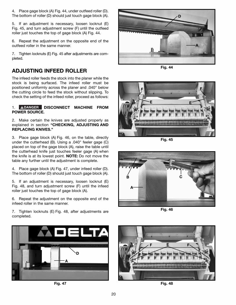
4. Place gage block (A) Fig. 44, under outfeed roller (D).The bottom of roller (D) should just touch gage block (A).
5. If an adjustment is necessary, loosen locknut (E)Fig. 45, and turn adjustment screw (F) until the outfeedroller just touches the top of gage block (A) Fig. 44.
6. Repeat the adjustment on the opposite end of theoutfeed roller in the same manner.
7. Tighten locknuts (E) Fig. 45 after adjustments are com-pleted.
Fig. 44
Fig. 45
Fig. 46
Fig. 48Fig. 47
ADJUSTING INFEED ROLLERThe infeed roller feeds the stock into the planer while thestock is being surfaced. The infeed roller must bepositioned uniformly across the planer and .040" belowthe cutting circle to feed the stock without slipping. Tocheck the setting of the infeed roller, proceed as follows:
1. DISCONNECT MACHINE FROMPOWER SOURCE.
2. Make certain the knives are adjusted properly asexplained in section “CHECKING, ADJUSTING ANDREPLACING KNIVES.”
3. Place gage block (A) Fig. 46, on the table, directlyunder the cutterhead (B). Using a .040" feeler gage (C)placed on top of the gage block (A), raise the table untilthe cutterhead knife just touches feeler gage (A) whenthe knife is at its lowest point. NOTE: Do not move thetable any further until the adjustment is complete.
4. Place gage block (A) Fig. 47, under infeed roller (D).The bottom of roller (D) should just touch gage block (A).
5. If an adjustment is necessary, loosen locknut (E)Fig. 48, and turn adjustment screw (F) until the infeedroller just touches the top of gage block (A).
6. Repeat the adjustment on the opposite end of theinfeed roller in the same manner.
7. Tighten locknuts (E) Fig. 48, after adjustments arecompleted.
D
A
F
E
F
E
CB
A
D
A
F FE

21
Fig. 49
Fig. 50
Fig. 51
Fig. 53Fig. 52
LEVELING THE TABLEThe table is set parallel to the cutterhead at the factoryand no further adjustment should be necessary. Tocheck if the table is level with the cutterhead, proceed asfollows:
1. DISCONNECT MACHINE FROMPOWER SOURCE.
2. Check to see if the cutterhead knives are setcorrectly as explained in section “CHECKING,ADJUSTING AND REPLACING KNIVES.”
3. Then check to see if the table is set parallel to thecutterhead by placing gage block (A) Fig. 49, directlyunder the cutterhead on the left hand side of the table asshown. Raise the table until gage block (A) Fig. 49, justtouches the cutterhead.
4. Carefully move gage block (A) Fig.50, to the righthand side of the table directly under the cutterhead. Thedistance from table to cutterhead should be identical.
5. If the table is not parallel to the cutterhead, lowerboot (B) Fig. 51, which is located underneath the table.NOTE: Table elevating handwheel must be unlockedwhen making this adjustment.
6. Loosen lock screw (C) Fig. 51, and with large pliers(D) turn adjustment sleeve (E) as necessary until table isparalell with the cutterhead. Tighten lock screw (C) afteradjustment is made and replace boot (B). NOTE: Thesame adjustment can also be made on the other side ofthe planer if necessary.
ADJUSTING TABLE HEIGHT SCALEThe table height scale indicates the distance the table isfrom the cutting circle (depth of cut). To check andadjust the pointer, proceed as follows:
1. Run a piece of wood through the planer and stop themachine.
2. Measure the thickness of the planed end of thestock as shown in Fig. 52. If an adjustment is necessary,loosen screw (A) Fig. 53, adjust pointer (B) and retightenscrew (A).
A
A
C
E
B
D
B
A

22
ADJUSTING TABLE GIBSIn the unlikely event of the table developing unwantedmovement during planing operations, the table can bechecked and adjusted as follows:
1. DISCONNECT MACHINE FROMPOWER SOURCE.
2. With the table in the locked position, and with afeeler gage, measure the gap between table gib (A) Fig.54 and table bracket (B). When set correctly the gapshould be .005".
3. If an adjustment is necessary, loosen three locknuts(C), and turn three adjustment screws (D) Fig. 54, asnecessary to set the correct gap.
4. Check and adjust the gap on the other side of thetable in the same manner. Tighten six locknuts, three ofwhich are shown at (C) Fig. 54, after adjustment ismade.
Fig. 54
C D
A
B
When using your machine, follow these few simple steps for achieving the best results.
1. True Up One Face – Feed one face of the board over a jointer, making thin cuts with each pass, until the entiresurface is flat.
2. Plane to Thickness – Place the side you planed in STEP 1 face down and feed the board through the planer. Planeuntil this side is flat, then plane both sides of the board until you are satisfied with the thickness. Make thin cuts,and alternate sides with each pass. If, during the planing operation, you notice the board twisting, warping, orbowing, repeat STEP 1 and true up one face.
3. When planing long stock, provide table extensions to support the infeed and outfeed end of the workpiece.
4. Plane with the grain only, and keep planer table clean. Occasionally, wax the table surface to reduce friction duringthe planing operation.
5. Cross-cut to Final Length – Cross-cut lumber to final length.
THE KNIVES ON THE PLANER WILL NOT WEAR EVENLY IF THE WOOD IS FED THROUGH THESAME SPOT ON THE TABLE EVERY TIME. FEED THE WOOD THROUGH THE PLANER ATDIFFERENT SPOTS ON THE TABLE TO HELP ELIMINATE UNEVEN WEAR OF THE KNIVES.
MACHINE USE
TROUBLESHOOTINGFor assistance with your machine, visit our website at www.deltamachinery.com for a list of service centers or callthe DELTA Machinery help line at 1-800-223-7278 (In Canada call 1-800-463-3582).
5. Raise and lower the table to its fullest range andcheck to see if the table moves up and down withoutbinding.
MAINTENANCEKEEP MACHINE CLEANPeriodically blow out all air passages with dry compressed air. All plastic parts should be cleaned with a soft damp cloth. NEVERuse solvents to clean plastic parts. They could possibly dissolve or otherwise damage the material.
Wear ANSI Z87.1 safety glasses while using compressed air.
FAILURE TO STARTShould your machine fail to start, check to make sure the prongs on the cord plug are making good contact in the outlet. Also,check for blown fuses or open circuit breakers in the line.

23
Fig. 55
B
A
LUBRICATING WORK SURFACESApply household floor paste wax to the machine table andextension table or other work surface weekly.
LUBRICATING THE FEED ROLLERSThe machine’s feed rollers must be lubricated about every 50 to 100hours of use or as needed. To lubricate the machine’s feed rollers,add a few drops of 10W Machine oil in the oil cups, two of whichare shown at (A) and (B) in Fig. 55. The other two are in the samelocation on the opposite side of the rollers.
PROTECTING CAST IRON FROM RUSTTo clean and protect cast iron tables from rust, you willneed the following materials: 1 pushblock from a jointer,1 sheet of medium Scotch-Brite™ Blending Hand Pad, 1can of WD-40®, 1 can of degreaser, 1 can of TopCote®
Aerosol. Apply the WD-40 and polish the table surface
with the Scotch-Brite pad using the pushblock as aholddown. Degrease the table, then apply the TopCote®
accordingly.
PARTS, SERVICE OR WARRANTY ASSISTANCEAll Delta Machines and accessories are manufactured to high quality standards and are serviced by a networkof Porter-Cable • Delta Factory Service Centers and Delta Authorized Service Stations. To obtain additionalinformation regarding your Delta quality product or to obtain parts, service, warranty assistance, or the locationof the nearest service outlet, please call 1-800-223-7278 (In Canada call 1-800-463-3582).
A complete line of accessories is available from your Delta Supplier, Porter-Cable • Delta Factory Service Centers,and Delta Authorized Service Stations. Please visit our Web Site www.deltamachinery.com for a catalog orfor the name of your nearest supplier.
Since accessories other than those offered by Delta have not been tested with this product, use of such accessories could be hazardous. For safest operation, only Delta recommended accessories should be used with this product.
ACCESSORIES
SERVICE
Two Year Limited New Product WarrantyDelta will repair or replace, at its expense and at its option, any new Delta machine, machine part, or machine accessorywhich in normal use has proven to be defective in workmanship or material, provided that the customer returns the productprepaid to a Delta factory service center or authorized service station with proof of purchase of the product within twoyears and provides Delta with reasonable opportunity to verify the alleged defect by inspection. For all refurbished Deltaproduct, the warranty period is 180 days. Delta may require that electric motors be returned prepaid to a motormanufacturer’s authorized station for inspection and repair or replacement. Delta will not be responsible for any asserteddefect which has resulted from normal wear, misuse, abuse or repair or alteration made or specifically authorized byanyone other than an authorized Delta service facility or representative. Under no circumstances will Delta be liable forincidental or consequential damages resulting from defective products. This warranty is Delta’s sole warranty and setsforth the customer’s exclusive remedy, with respect to defective products; all other warranties, express or implied, whetherof merchantability, fitness for purpose, or otherwise, are expressly disclaimed by Delta.
WARRANTY

The following are trademarks of PORTER-CABLE • DELTA (Las siguientes son marcas registradas de PORTER-CABLE • DELTA S.A.) (Les marquessuivantes sont des marques de fabriquant de la PORTER-CABLE • DELTA): Auto-Set®, BAMMER®, B.O.S.S.®, Builder’s Saw®, Contractor’s Saw®,Contractor’s Saw II™, Delta®, DELTACRAFT®, DELTAGRAM™, Delta Series 2000™, DURATRONIC™, Emc²™, FLEX®, Flying Chips™, FRAME SAW®,Grip Vac™, Homecraft®, INNOVATION THAT WORKS®, Jet-Lock®, JETSTREAM®, ‘kickstand®, LASERLOC®, MICRO-SET®, Micro-Set®, MIDI LATHE®,MORTEN™, NETWORK™, OMNIJIG®, POCKET CUTTER®, PORTA-BAND®, PORTA-PLANE®, PORTER-CABLE®&(design), PORTER-CABLE®PROFESSIONAL POWER TOOLS, PORTER-CABLE REDEFINING PERFORMANCE™, Posi-Matic®, Q-3®&(design), QUICKSAND®&(design),QUICKSET™, QUICKSET II®, QUICKSET PLUS™, RIPTIDE™&(design), SAFE GUARD II®, SAFE-LOC®, Sanding Center®, SANDTRAP®&(design), SAWBOSS®, Sawbuck™, Sidekick®, SPEED-BLOC®, SPEEDMATIC®, SPEEDTRONIC®, STAIR EASE®, The American Woodshop®&(design), The LumberCompany®&(design), THE PROFESSIONAL EDGE®, THE PROFESSIONAL SELECT®, THIN-LINE™, TIGER®, TIGER CUB®, TIGER SAW®,TORQBUSTER®, TORQ-BUSTER®, TRU-MATCH™, TWIN-LITE®, UNIGUARD®, Unifence®, UNIFEEDER™, Unihead®, Uniplane™, Unirip®, Unisaw®,Univise®, Versa-Feeder®, VERSA-PLANE® , WHISPER SERIES®, WOODWORKER’S CHOICE™. Trademarks noted with ™ and ® are registered in the United States Patent and Trademark Office and may also be registered in other countries. LasMarcas Registradas con el signo de ™ y ® son registradas por la Oficina de Registros y Patentes de los Estados Unidos y también pueden estarregistradas en otros países.
PORTER-CABLE • DELTA SERVICE CENTERS(CENTROS DE SERVICIO DE PORTER-CABLE • DELTA)
Parts and Repair Service for Porter-Cable • Delta Machinery are Available at These Locations(Obtenga Refaccion de Partes o Servicio para su Herramienta en los Siguientes Centros de Porter-Cable • Delta)
Authorized Service Stations are located in many large cities. Telephone 800-438-2486 or 731-541-6042 for assistance locating one.Parts and accessories for Porter-Cable·Delta products should be obtained by contacting any Porter-Cable·Delta Distributor, AuthorizedService Center, or Porter-Cable·Delta Factory Service Center. If you do not have access to any of these, call 800-223-7278 and you willbe directed to the nearest Porter-Cable·Delta Factory Service Center. Las Estaciones de Servicio Autorizadas están ubicadas en muchasgrandes ciudades. Llame al 800-438-2486 ó al 731-541-6042 para obtener asistencia a fin de localizar una. Las piezas y los accesoriospara los productos Porter-Cable·Delta deben obtenerse poniéndose en contacto con cualquier distribuidor Porter-Cable·Delta, Centrode Servicio Autorizado o Centro de Servicio de Fábrica Porter-Cable·Delta. Si no tiene acceso a ninguna de estas opciones, llame al800-223-7278 y le dirigirán al Centro de Servicio de Fábrica Porter-Cable·Delta más cercano.
ARIZONAPhoenix 85013-29064501 N. 7th Ave.Phone: (602) 279-6414Fax: (602) 279-5470
CALIFORNIAOntario 91761 (Los Angeles)3949A East Guasti RoadPhone: (909) 390-5555Fax: (909) 390-5554
San Diego 921117290 Clairemont Mesa Blvd.Phone: (858) 279-2011Fax: (858) 279-0362
San Leandro 94577 (Oakland)3039 Teagarden StreetPhone: (510) 357-9762Fax: (510) 357-7939
COLORADODenver 80223700 West Mississippi Ave.Phone: (303) 922-8325Fax: (303) 922-0245
FLORIDADavie 33314 (Miami)4343 South State Rd. 7 (441)Unit #107Phone: (954) 321-6635Fax: (954) 321-6638
Tampa 336344909 West Waters Ave.Phone: (813) 884-0434Fax: (813) 888-5997
GEORGIAForest Park 30297 (Atlanta)5442 Frontage Road,Suite 112Phone: (404) 608-0006Fax: (404) 608-1123
ILLINOISAddison 60101 (Chicago)400 South Rohlwing Rd.Phone: (630) 424-8805Fax: (630) 424-8895
KANSASOverland Park 662149201 Quivira RoadPhone: (913) 495-4330Fax: (913) 495-4378
MARYLANDElkridge 21075 (Baltimore)7397-102 Washington Blvd.Phone: (410) 799-9394Fax: (410) 799-9398
MASSACHUSETTSFranklin 02038 (Boston)Franklin Industrial Park101E Constitution Blvd.Phone: (508) 520-8802Fax: (508) 528-8089
MICHIGANMadison Heights 48071 (Detroit)30475 Stephenson HighwayPhone: (248) 597-5000Fax: (248) 597-5004
MINNESOTAEden Prairie 553449709 Valley View RoadPhone: (952) 884-9191Fax: (952) 884-3750
MISSOURISt. Louis 6314611477 Page Service DrivePhone: (314) 997-9100Fax: (314) 997-9183
NEW YORKFlushing 11365-1595 (N.Y.C.)175-25 Horace Harding Expwy.Phone: (718) 225-2040Fax: (718) 423-9619
NORTH CAROLINACharlotte 282709129 Monroe Road, Suite 115Phone: (704) 841-1176Fax: (704) 708-4625
OHIOColumbus 432291948 Schrock RoadPhone: (614) 895-3112Fax: (614) 895-3187
Parma Heights OH 441306485 Pearl RoadPhone: (440) 842-9100Fax: (440) 884-3430
OREGONPortland 9723014811 North East Airport WayPhone: (503) 255-6556Fax: (503) 255-6543
PENNSYLVANIAWillow Grove 19090(Philadelphia)520 North York RoadPhone: (215) 658-1430Fax: (215) 658-1433
TEXASCarrollton 75006 (Dallas)1300 Interstate 35 N, Suite 112Phone: (972) 446-2996Fax: (972) 446-8157
Houston 77022-2122536 East Tidwell Rd.Phone: (713) 692-7111Fax: (713) 692-1107
WASHINGTONAuburn 98001(Seattle)3320 West Valley HWY, NorthBuilding D, Suite 111Phone: (253) 333-8353Fax: (253) 333-9613
PC7.2-0105-149
CANADIAN PORTER-CABLE • DELTA SERVICE CENTERSALBERTABay 6, 2520-23rd St. N.E.Calgary, AlbertaT2E 8L2Phone: (403) 735-6166Fax: (403) 735-6144
BRITISH COLUMBIA8520 Baxter PlaceBurnaby, B.C.V5A 4T8Phone: (604) 420-0102Fax: (604) 420-3522
MANITOBA1699 Dublin AvenueWinnipeg, ManitobaR3H 0H2Phone: (204) 633-9259Fax: (204) 632-1976
ONTARIO505 Southgate DriveGuelph, OntarioN1H 6M7Phone: (519) 767-4132Fax: (519) 767-4131
QUÉBEC1515 ave.St-Jean Baptiste, Suite 160Québec, QuébecG2E 5E2Phone: (418) 877-7112Fax: (418) 877-7123
1447, BeginSt-Laurent, (Montréal),QuébecH4R 1V8Phone: (514) 336-8772Fax: (514) 336-3505