Embed Size (px)
Citation preview
Instruction Manual: SLS (Payload Fairing - CEV) Author: David Brown
1
Instruction Manual: Space Launch System Payload Fairing – Manned CEV Flights
Designer’s comments: This model has been designed without the benefit of engineering blueprints. Only publically available conceptual diagrams and illustrations have been used. As a consequence of this, a certain degree of ‘artistic licence’ has been used to create a model that exhibits at least a modicum of realism.
The assembly of a model should follow a procedure that vaguely resembles the method for cooking a meal; i.e.
• Prepare a place where you can work, without distractions. • Get all of your equipment (utensils) out and ready. • Get all of your parts for the model (ingredients) printed, cut out and ready to start. • Lastly, try to have a location for your model prepared in advance, so that when it is finished, you will
know where to place it.
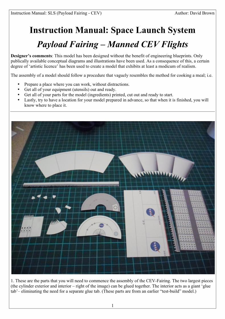
1. These are the parts that you will need to commence the assembly of the CEV-Fairing. The two largest pieces (the cylinder exterior and interior – right of the image) can be glued together. The interior acts as a giant ‘glue tab’– eliminating the need for a separate glue tab. (These parts are from an earlier “test-build” model.)
Instruction Manual: SLS (Payload Fairing - CEV) Author: David Brown
2
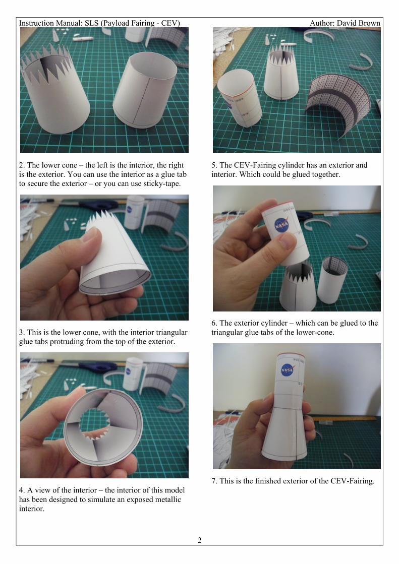
2. The lower cone – the left is the interior, the right is the exterior. You can use the interior as a glue tab to secure the exterior – or you can use sticky-tape.
3. This is the lower cone, with the interior triangular glue tabs protruding from the top of the exterior.
4. A view of the interior – the interior of this model has been designed to simulate an exposed metallic interior.
5. The CEV-Fairing cylinder has an exterior and interior. Which could be glued together.
6. The exterior cylinder – which can be glued to the triangular glue tabs of the lower-cone.
7. This is the finished exterior of the CEV-Fairing.
Instruction Manual: SLS (Payload Fairing - CEV) Author: David Brown
3
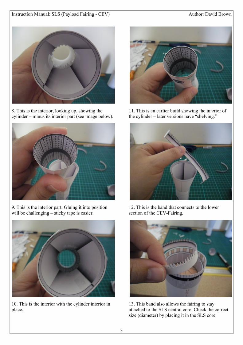
8. This is the interior, looking up, showing the cylinder – minus its interior part (see image below).
9. This is the interior part. Gluing it into position will be challenging – sticky tape is easier.
10. This is the interior with the cylinder interior in place.
11. This is an earlier build showing the interior of the cylinder – later versions have “shelving.”
12. This is the band that connects to the lower section of the CEV-Fairing.
13. This band also allows the fairing to stay attached to the SLS central core. Check the correct size (diameter) by placing it in the SLS core.
Instruction Manual: SLS (Payload Fairing - CEV) Author: David Brown
4
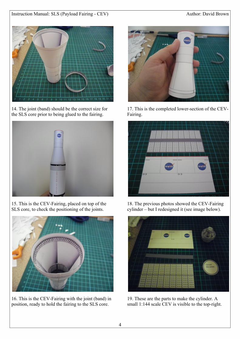
14. The joint (band) should be the correct size for the SLS core prior to being glued to the fairing.
15. This is the CEV-Fairing, placed on top of the SLS core, to check the positioning of the joints.
16. This is the CEV-Fairing with the joint (band) in position, ready to hold the fairing to the SLS core.
17. This is the completed lower-section of the CEV-Fairing.
18. The previous photos showed the CEV-Fairing cylinder – but I redesigned it (see image below).
19. These are the parts to make the cylinder. A small 1:144 scale CEV is visible to the top-right.
Instruction Manual: SLS (Payload Fairing - CEV) Author: David Brown
5
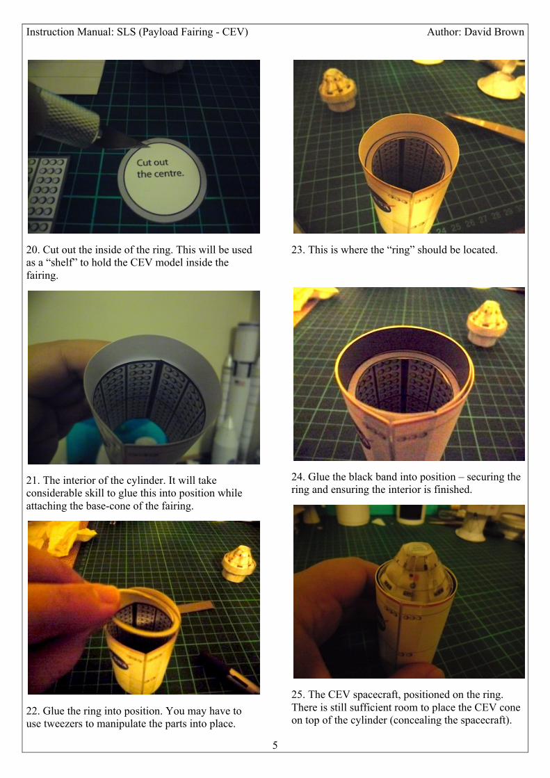
20. Cut out the inside of the ring. This will be used as a “shelf” to hold the CEV model inside the fairing.
21. The interior of the cylinder. It will take considerable skill to glue this into position while attaching the base-cone of the fairing.
22. Glue the ring into position. You may have to use tweezers to manipulate the parts into place.
23. This is where the “ring” should be located.
24. Glue the black band into position – securing the ring and ensuring the interior is finished.
25. The CEV spacecraft, positioned on the ring. There is still sufficient room to place the CEV cone on top of the cylinder (concealing the spacecraft).
Instruction Manual: SLS (Payload Fairing - CEV) Author: David Brown
6
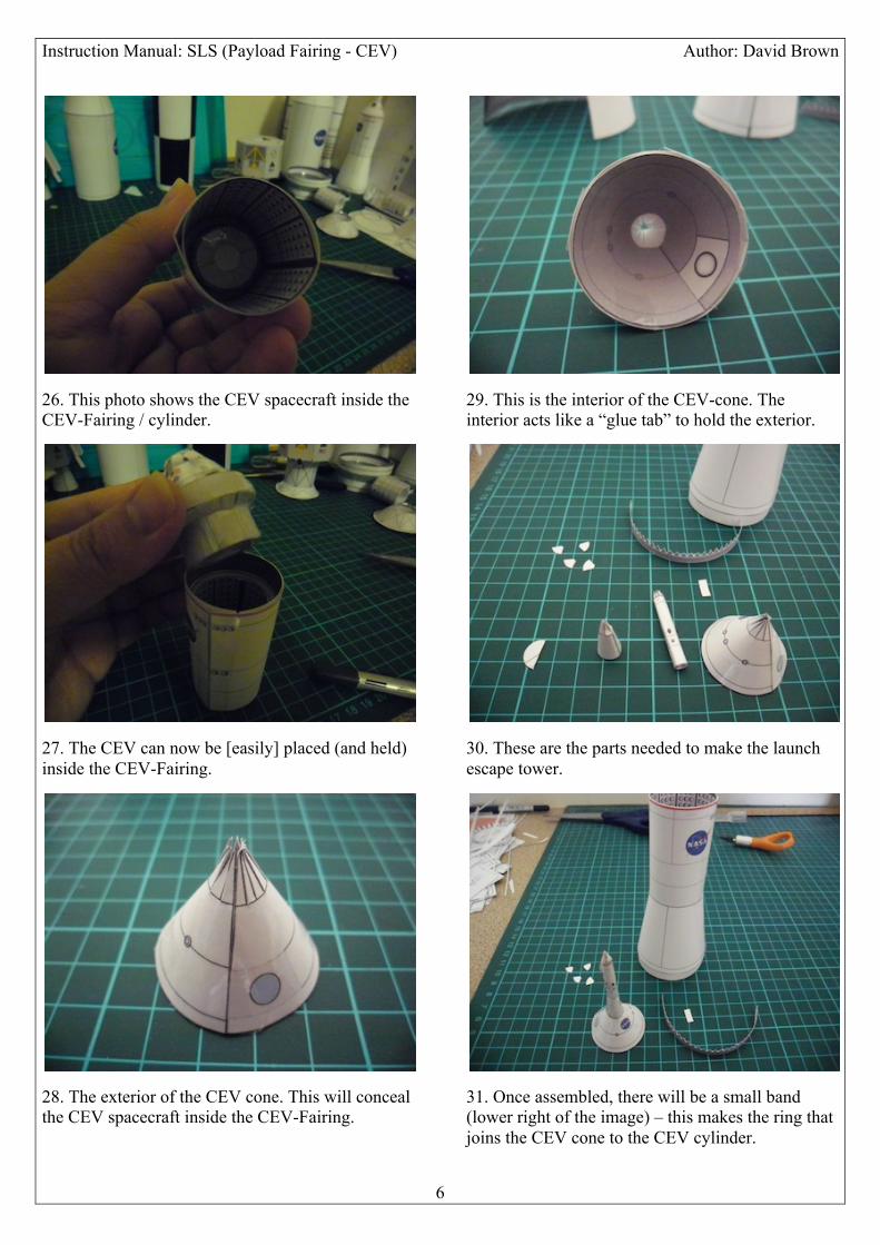
26. This photo shows the CEV spacecraft inside the CEV-Fairing / cylinder.
27. The CEV can now be [easily] placed (and held) inside the CEV-Fairing.
28. The exterior of the CEV cone. This will conceal the CEV spacecraft inside the CEV-Fairing.
29. This is the interior of the CEV-cone. The interior acts like a “glue tab” to hold the exterior.
30. These are the parts needed to make the launch escape tower.
31. Once assembled, there will be a small band (lower right of the image) – this makes the ring that joins the CEV cone to the CEV cylinder.
Instruction Manual: SLS (Payload Fairing - CEV) Author: David Brown
7
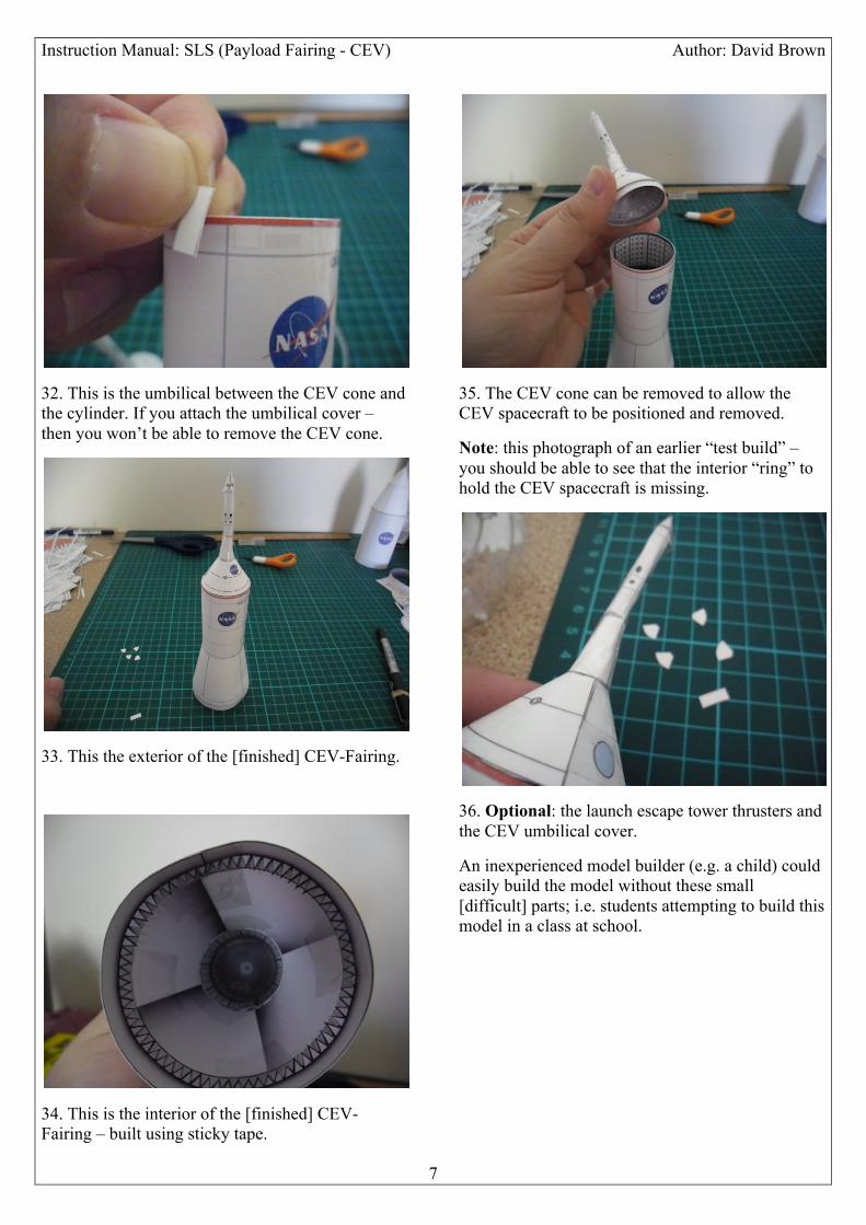
32. This is the umbilical between the CEV cone and the cylinder. If you attach the umbilical cover – then you won’t be able to remove the CEV cone.
33. This the exterior of the [finished] CEV-Fairing.
34. This is the interior of the [finished] CEV-Fairing – built using sticky tape.
35. The CEV cone can be removed to allow the CEV spacecraft to be positioned and removed.
Note: this photograph of an earlier “test build” – you should be able to see that the interior “ring” to hold the CEV spacecraft is missing.
36. Optional: the launch escape tower thrusters and the CEV umbilical cover.
An inexperienced model builder (e.g. a child) could easily build the model without these small [difficult] parts; i.e. students attempting to build this model in a class at school.