Embed Size (px)
Citation preview
1
Van
derb
ilt
Un
ivers
ity
Vibro-AcousticsLaboratory
Decentralized Structural Acoustic Control of a Launch Vehicle
Payload FairingKenneth D Frampton
Dept. of Mechanical Engineering
Vanderbilt University
Van
derb
ilt
Un
ivers
ity
Vibro-AcousticsLaboratory
Objectives Develop decentralized control systems for launch
vehicle payload fairings Control of fairing vibro-acoustic response based on
group management middleware services– Groups assigned by modal sensitivity– Groups assigned geographically
Investigate the effects of networked embedded systems constraints on control performance
Van
derb
ilt
Un
ivers
ity
Vibro-AcousticsLaboratory
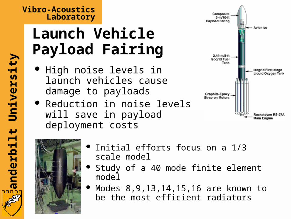
Launch Vehicle Payload Fairing
Initial efforts focus on a 1/3 scale model Study of a 40 mode finite element model Modes 8,9,13,14,15,16 are known to be
the most efficient radiators
High noise levels in launch vehicles cause damage to payloads
Reduction in noise levels will save in payload deployment costs
Van
derb
ilt
Un
ivers
ity
Vibro-AcousticsLaboratory
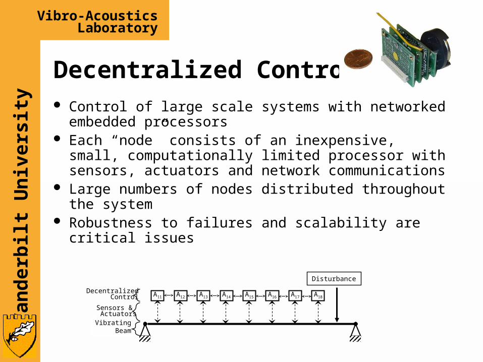
Decentralized Control Control of large scale systems with networked
embedded processors Each “node” consists of an inexpensive, small,
computationally limited processor with sensors, actuators and network communications
Large numbers of nodes distributed throughout the system
Robustness to failures and scalability are critical issues
A11 A12 A13 A14 A15 A16 A17 A18
Disturbance
VibratingBeam
Sensors & Actuators
DecentralizedControl
Van
derb
ilt
Un
ivers
ity
Vibro-AcousticsLaboratory
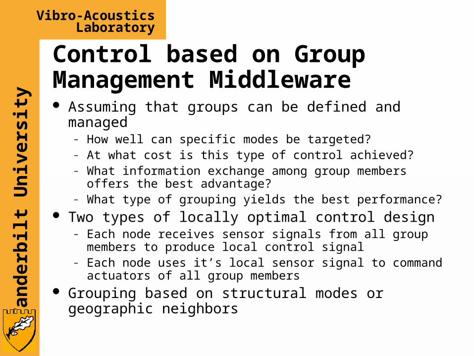
Control based on Group Management Middleware Assuming that groups can be defined and managed
– How well can specific modes be targeted?– At what cost is this type of control achieved?– What information exchange among group members offers
the best advantage?– What type of grouping yields the best performance?
Two types of locally optimal control design– Each node receives sensor signals from all group members
to produce local control signal– Each node uses it’s local sensor signal to command
actuators of all group members Grouping based on structural modes or geographic
neighbors
Van
derb
ilt
Un
ivers
ity
Vibro-AcousticsLaboratory
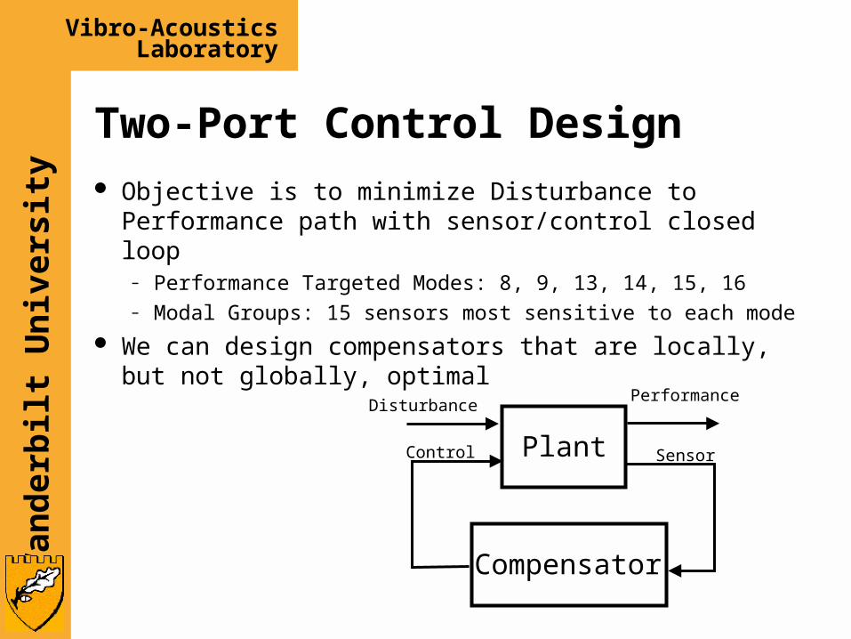
Two-Port Control Design Objective is to minimize Disturbance to Performance
path with sensor/control closed loop– Performance Targeted Modes: 8, 9, 13, 14, 15, 16– Modal Groups: 15 sensors most sensitive to each mode
We can design compensators that are locally, but not globally, optimal
Plant
Compensator
DisturbancePerformance
Control Sensor
Van
derb
ilt
Un
ivers
ity
Vibro-AcousticsLaboratory
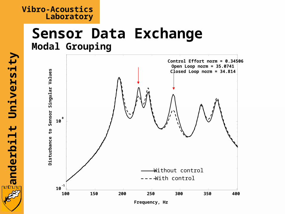
Sensor Data ExchangeModal Grouping
100 150 200 250 300 350 40010
-1
100
Control Effort norm = 0.34506Open Loop norm = 35.0741Closed Loop norm = 34.814
Without control
With control
Frequency, Hz
Dis
turb
ance
to
Sen
sor
Sin
gu
lar
Val
ues
Van
derb
ilt
Un
ivers
ity
Vibro-AcousticsLaboratory
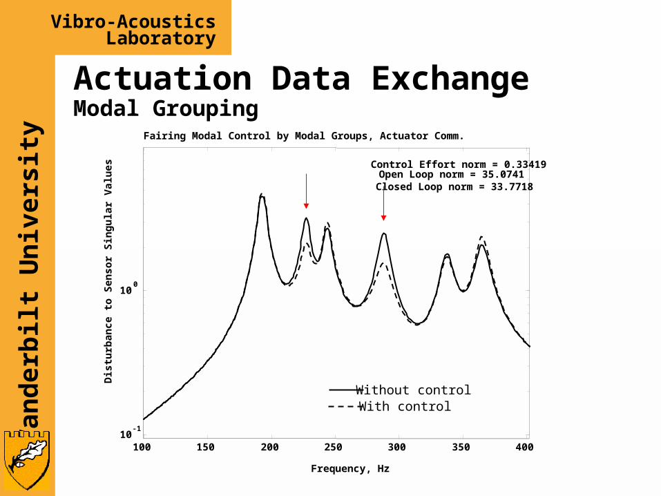
Actuation Data ExchangeModal Grouping
100 150 200 250 300 350 40010
-1
100
Control Effort norm = 0.33419Open Loop norm = 35.0741Closed Loop norm = 33.7718
Fairing Modal Control by Modal Groups, Actuator Comm.
Without controlWith control
Frequency, Hz
Dis
turb
ance
to
Sen
sor
Sin
gu
lar
Val
ues
Van
derb
ilt
Un
ivers
ity
Vibro-AcousticsLaboratory
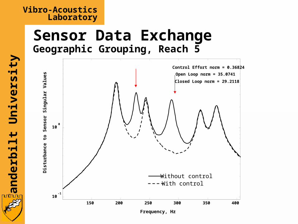
Sensor Data ExchangeGeographic Grouping, Reach 5
150 200 250 300 350 400
10-1
100
Control Effort norm = 0.36824
Open Loop norm = 35.0741
Closed Loop norm = 29.2118
Frequency, Hz
Dis
turb
ance
to
Sen
sor
Sin
gu
lar
Val
ues
Without controlWith control
Van
derb
ilt
Un
ivers
ity
Vibro-AcousticsLaboratory
Effects of Communication Delay
Effects established through SIESTA simulations of beam vibration control
Control system sampling rate of 2 kHz 100 node system Delays accumulate as signals are passed
from node to node
Van
derb
ilt
Un
ivers
ity
Vibro-AcousticsLaboratory
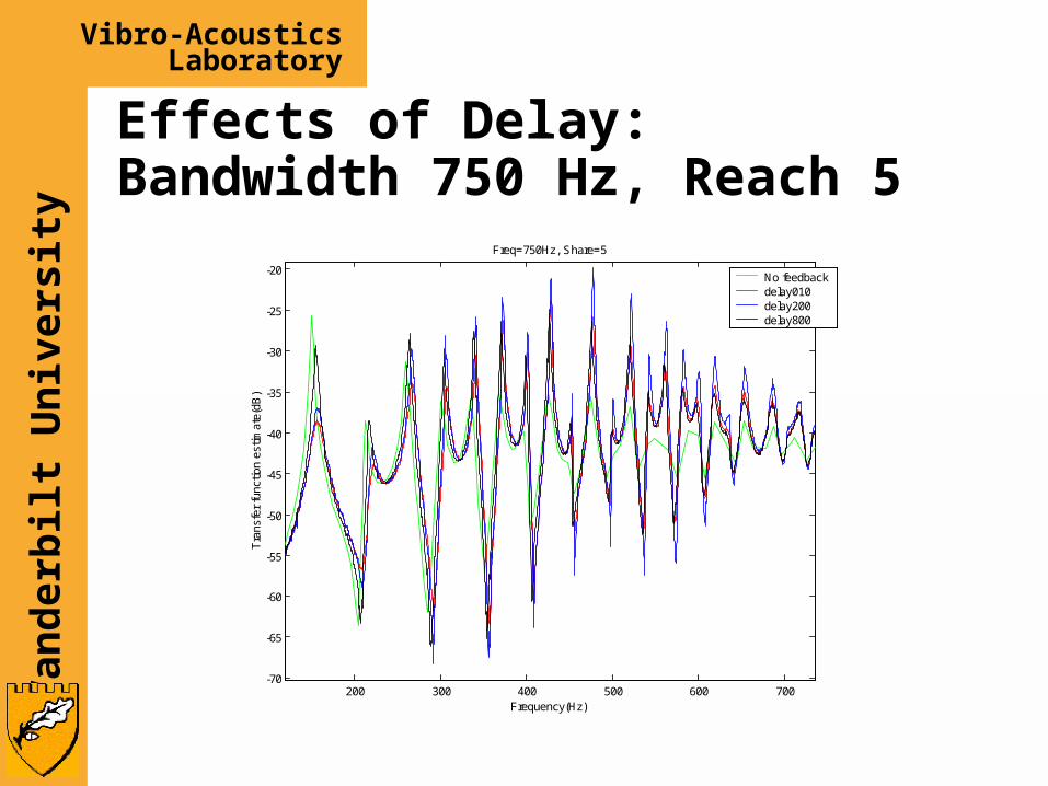
Effects of Delay:Bandwidth 750 Hz, Reach 5
200 300 400 500 600 700-70
-65
-60
-55
-50
-45
-40
-35
-30
-25
-20
Freq=750Hz, Share=5
Frequency(Hz)
Tra
nsfe
r fu
nctio
n es
timat
e(dB
)
No feedbackdelay010delay200delay800
Van
derb
ilt
Un
ivers
ity
Vibro-AcousticsLaboratory
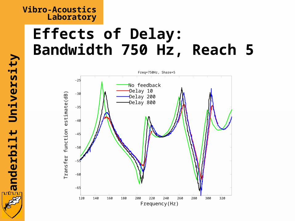
Effects of Delay:Bandwidth 750 Hz, Reach 5
120 140 160 180 200 220 240 260 280 300 320
-65
-60
-55
-50
-45
-40
-35
-30
-25
Freq=750Hz, Share=5
Frequency(Hz)
Tra
nsf
er
fun
ctio
n e
stim
ate
(dB
)
No feedbackDelay 10Delay 200Delay 800
Van
derb
ilt
Un
ivers
ity
Vibro-AcousticsLaboratory
Conclusions Fairing Control
– Specific modes can be targeted for control– Control effort and spillover are not a problem– Sensor data exchange among nodes is not necessarily the best
approach. Exchanging control signals or a mixed approach may be preferable.
– Geographic grouping may be as good as modal grouping IF you have a good model and good design tools
Effects of Delay– For a system with a bandwidth in the hundreds of Hz and a sampling
rate of 2 kHz, delays on the order of hundreds of microseconds can result in significant degradation in performance.
– The reach of the system is affects the impact due to accumulated delays