Embed Size (px)
Citation preview
D9930136, Revision B
Rosemount Aerospace Inc. became an ISO 9001certified company in July of 1999.
Rosemount Aerospace Inc. 1999, 2001
INSTRUCTION MANUALSERIES 162
STANDARD PLATINUM RESISTANCE THERMOMETERSMODELS 162CE, 162CG, 162D, 162K
Isotech North America158 Brentwood Drive, Unit 4 Colchester, VT 05446
Phone: (802) 863-8050 Fax: (802) 863-8125
[email protected] www.isotechna.com
Rosemount Aerospace Inc.D9930136, Revision B
TABLE OF CONTENTS
1. INTRODUCTION.................................................................................................................................................1
2. INSTALLATION ..................................................................................................................................................2
3. OPERATION.........................................................................................................................................................5
4. CALIBRATION ..................................................................................................................................................10
5. MAINTENANCE................................................................................................................................................12
6. RETURN OF HARDWARE ...............................................................................................................................14
7. SUGGESTED READING ...................................................................................................................................15
LIST OF FIGURES
FIGURE PAGE
1. Long-stem SPRT Mounted in Stirred Liquid Bath ........................................................................................ 32. Cryogenic or Special Purpose Metal Block Installation-Model 162D........................................................... 43. Electrical Schematics ..................................................................................................................................... 64. Typical Stem Conduction Error in Stirred Ice Bath....................................................................................... 95. Approximate Change in W(t) for Shift in R(0.01°C) Equivalent to 0.002°C, 0.005°C, and 0.010°C ......... 11
LIST OF TABLES
TABLE PAGE
1. Series 162 SPRTs........................................................................................................................................... 12. Recommended Well Diameter ....................................................................................................................... 33. Nominal Resistance versus Temperature ....................................................................................................... 74. Total Self Heating in Ice Bath or Triple Point of Water Cell......................................................................... 85. Recommended Annealing Temperature....................................................................................................... 13
LIST OF APPENDICES
APPENDIX PAGE
A. Specification Control Drawings............................................................................................................... A-1
Rosemount Aerospace Inc.D9930136, Revision B
1
1. INTRODUCTION
This manual provides information for installing, operating, and maintaining your series 162Standard Platinum Resistance Thermometer (SPRT).
1.1 Description
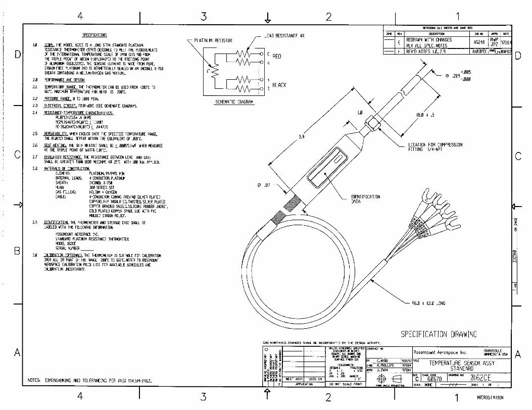
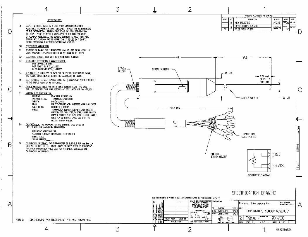
The SPRT is the defining interpolating instrument on the International Temperature Scale of1990 (ITS-90) from approximately -259°C to 962°C. This wide temperature range requiresseveral thermometer types, which are included as part of the 162 series shown in Table 1.
Table 1. Series 162 SPRTs
Model SPRT Type Range162CE Long-stem, metal-sheath,
R(0.01°C)=25.5 ohms-200°C to 661°C
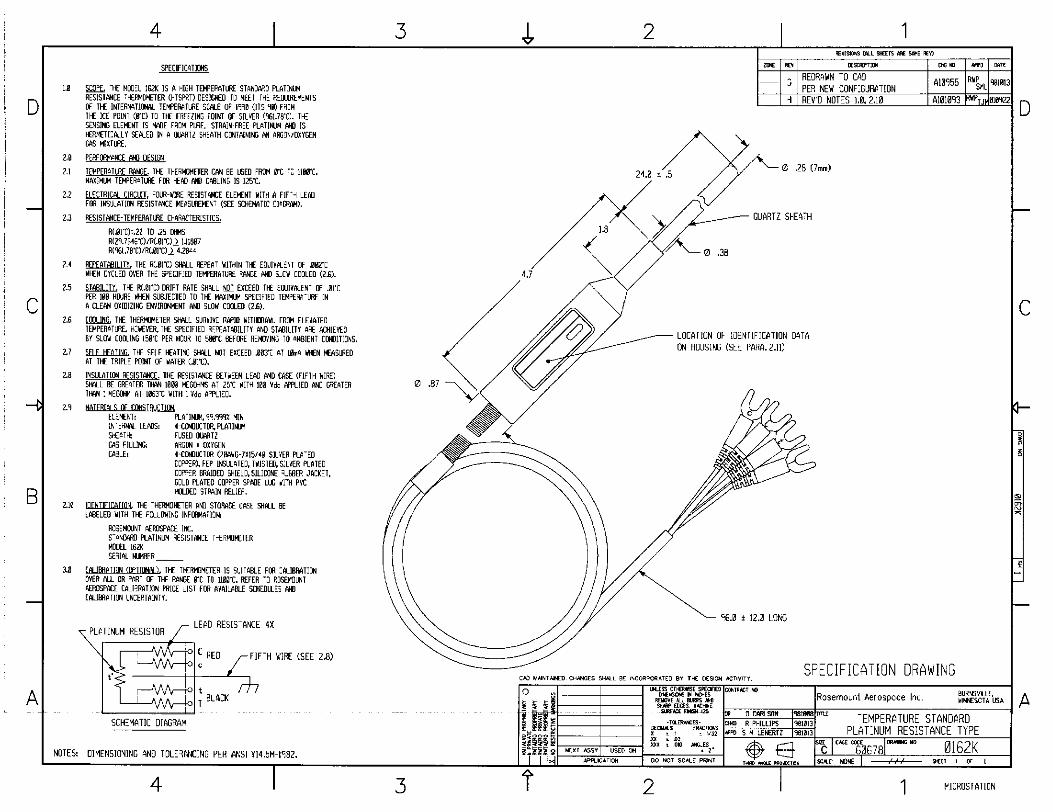
162CG Long-stem, quartz-sheath,R(0.01°C)=25.5 ohms
-200°C to 661°C
162D Capsule, metal-sheath,R(0.01°C)=25.5 ohms
-269°C to 250°C
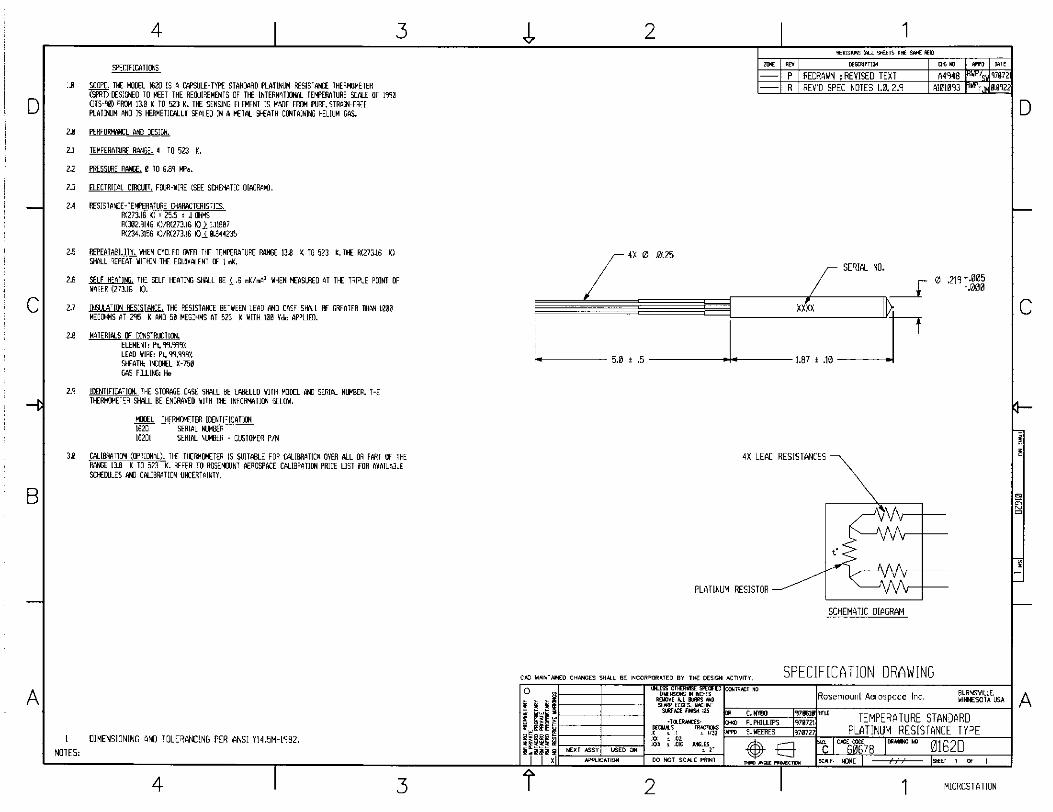
162K Long-stem, quartz-sheath,R(0.01°C)=0.25 ohms
0°C to 1100°C
The resistance-temperature characteristics are described in terms of the ratio of resistance R(t) attemperature t and the resistance R(0.01°C) at the triple point of water. The 162 SPRTs areconstructed with pure, strain-free platinum and satisfy the ITS-90 criteria:
R(29.7646°C)/R(0.01°C) ≥1.11807, andR(-38.8344°C)/R(0.01°C) ≤0.844235.
The high temperature SPRT model 162K also satisfies the criterion:
R(961.78°C)/R(0.01°C) ≥4.2844.
A more detailed description of your thermometer is included in the Specification ControlDrawing (see Appendix A).
1.2 Calibration
A SPRT must be calibrated before it can be used for accurate temperature measurement.Rosemount Aerospace provides calibration services traceable to the National Institute ofStandards and Technology (NIST) for all series 162 thermometers. Alternatively, thethermometer may be submitted directly to the NIST or other national standards laboratory.Additional information on calibration is provided in Section 4, Calibration.
Rosemount Aerospace Inc.D9930136, Revision B
2
1.3 Getting Started
Before using your thermometer, understand the capability of your SPRT and the equipment usedwith the thermometer. The following checklist includes important first steps to take towardsachieving your accuracy and cost goals.
! The application temperature is within the SPRT specification (see Appendix A).! The fluid is compatible with the thermometer (see 2.3).! The installation has low vibration and adequate clearance (see 2.3).! The thermometer is connected for a 4-wire measurement (see 3.1).! The resistance measuring equipment is appropriate for uncertainty budget (see 3.2).! The excitation current is selected to prevent appreciable self-heating error (see 3.2.1).! The immersion depth is sufficient to minimize stem conduction errors (see 3.3).! The thermometer has a valid calibration (see 4).
1.4 Technical Support
For technical assistance, contact our Metrology Products Group (phone: 651-681-8900, fax: 651-681-8909).
2. INSTALLATION
2.1 General
The calibration equipment used with the series 162 thermometers should be located in alaboratory environment conducive to precise measurements:
- Quiet, clean, and draft free- Minimal vibration- Low radio frequency, magnetic and electrical interference- Stable temperature and humidity
2.2 Handling
The series 162 thermometers are delicate instruments that must be handled carefully to maintaincalibration accuracy. Vibration or mechanical shock will strain the platinum sensing elementcausing the resistance to increase with time. Careful handling will prolong thermometer life andreduce the need for recalibration. When not in use, store the thermometer in its protective storagecase.
The quartz sheath thermometers (162CG and 162K) require special attention. Besides beingextremely fragile, surface contaminants will promote devetrification of the quartz at hightemperatures. Never touch the sheath with bare hands. If handling is necessary, disposable plastic(powder-free) gloves or finger cots are recommended. As a precaution, wipe the sheath withalcohol to remove fingerprints and other debris before exposing it to elevated temperatures.
Rosemount Aerospace Inc.D9930136, Revision B
3
2.3 Mounting
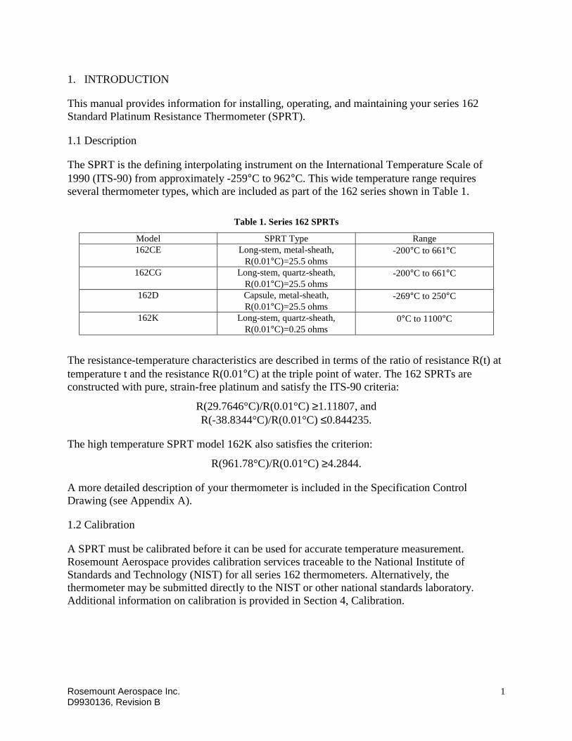
The series 162 thermometers may be mounted for either horizontal or vertical installation. Atypical installation is shown in Figure 1.
Figure 1. Long-stem SPRT Mounted in Stirred Liquid Bath
When used with a metal block or other rigid fixture, the clearance between the thermometersheath and block should be sized to promote good thermal contact and allow easy insertion andremoval. Recommended minimum well diameters are included in Table 2. For larger wells,thermal contact can be improved by using a bushing positioned over the sensing portion of thethermometer tip.
Table 2. Recommended Well Diameter
Model Recommended Minimum Well Diameter162CE, 162D 5.7 mm (0.226 inches)162CG, 162K 7.75 mm (0.295 inches)
For the long-stem thermometers, the head and external lead wires are designed to remain nearambient conditions (see Appendix A for temperature limits). The thermometer head should notbe submerged in liquid or chilled to form surface condensation since this could cause lowinsulation resistance between the lead wires. Additional mounting considerations for specificmodels are included below.
Rosemount Aerospace Inc.D9930136, Revision B
4
2.3.1 162CE
The model 162CE has a nickel-chromium alloy (Inconel X-750) sheath that is compatible withall common calibration media. A compression fitting may be installed on the 6.4 mm (0.250inch) diameter portion of the sheath (see Appendix A) to allow use under pressures up to 13.8MPa (2000 psia).
2.3.2 162D
The model 162D can be immersed directly in any nonconductive fluid compatible with thematerials of construction. Wetted surfaces include nickel-chromium alloy (Inconel X-750),platinum, glass, and silver solder alloy.
Additional wire is often needed to extend the lead wire to the readout device. Copper wire,typically 26 gage or smaller, can be joined to the platinum wire with silver solder (BAg-7). Thesolder joint should be at least 18 mm (0.7 inch) from the glass seal. A Teflon or similar sleevingshould be positioned over each lead wire to prevent a short circuit between lead wires or toground.
CAUTION: DO NOT BEND OR OVERHEAT THE PINS AND PLATINUM LEAD WIREADJACENT TO THE HOUSING.
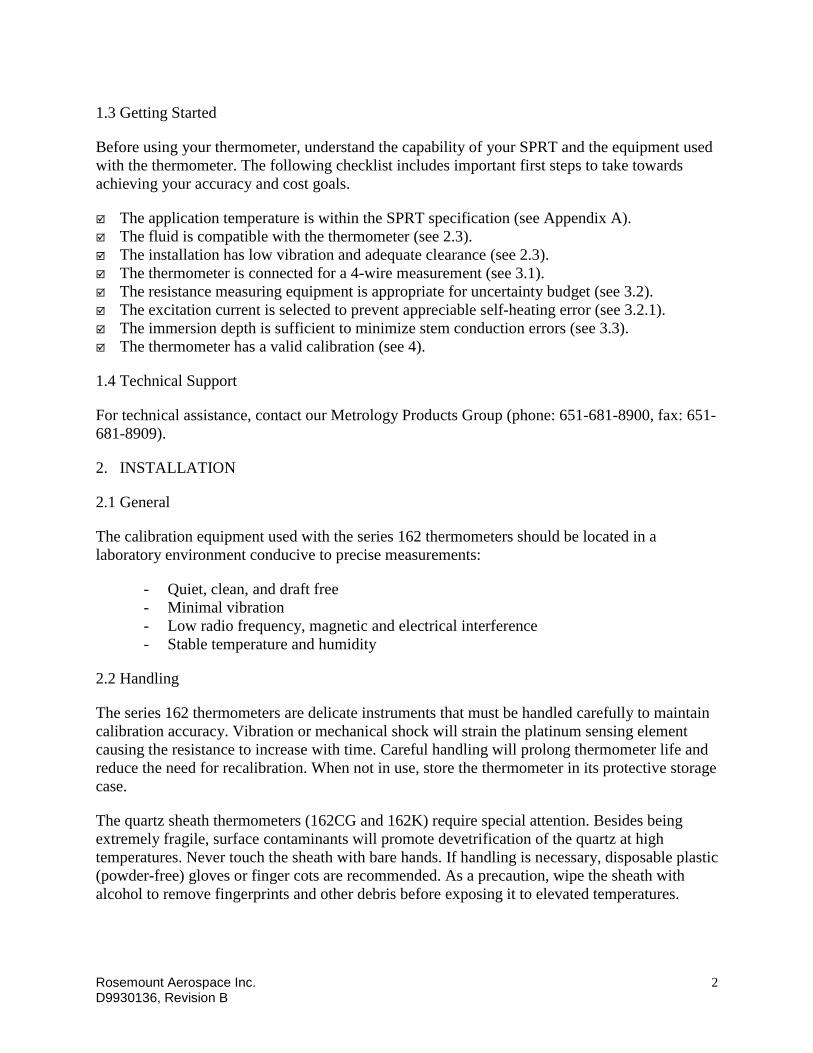
To minimize conduction errors, the thermometer and lead wire must be at approximately thesame temperature. For cryostat applications, a small diameter extension wire is used andstrapped to the calibration block as shown in Figure 2. This also provides strain relief for thedelicate lead wires.
Figure 2. Cryogenic or Special Purpose Metal Block Installation-Model 162D
Rosemount Aerospace Inc.D9930136, Revision B
5
2.3.3 162CG and 162K
Models 162CG and 162K have fused quartz (SiO2) sheaths that are compatible with mostcalibration fluids except for salts. Direct exposure to salt bath fluids will cause the sheath to spalland eventually lead to mechanical failure. For salt bath applications, the thermometer must beplaced into a protective tube made of a corrosion resistant material such as 316 stainless steel.
At temperatures above approximately 600°C, fused quartz is not impervious to elements that cancontaminate the platinum sensing element. The risk of contamination increases exponentiallywith temperature. When used in a furnace with exposed heating elements or other metal objects,the thermometer must be used with a dense protective tube compatible with quartz and platinum.Tubes made of platinum or more economical high purity aluminum oxide (99.8% min.) haveproven to be effective diffusion barriers.
3. OPERATION
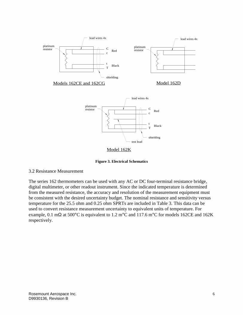
3.1 Thermometer Circuit
The series 162 thermometers include four lead wires so that lead resistances are effectivelycancelled when used with a four-terminal resistance bridge or other readout instrument (seeFigure 3). The model 162K also has a fifth lead wire that runs between the sensing element andhousing. The fifth lead is positioned equidistant from the four element lead wires and is used totest insulation resistance.
The long-stem SPRTs include a molded strain relief on each spade lug, which is color codedblack or red to identify common lead wires. The spade lugs are also stamped with the traditionaldesignations "C" and "T" for the current carrying (source) leads and "c" and "t" for the potential(sense) leads. However, all the leads are identically constructed and matched within 0.005 ohmsat the factory. Under most circumstances, it makes no difference which pair of leads is used forcurrent and potential. Contact the factory if your application requires the lead resistancestrimmed to a tighter tolerance.
The external lead wire cable is fully shielded and isolated from the thermometer head. If needed,a guard wire can be attached to the shielding at the lug end of the cable by removing a smallportion of the silicone rubber jacket.
Rosemount Aerospace Inc.D9930136, Revision B
6
Figure 3. Electrical Schematics
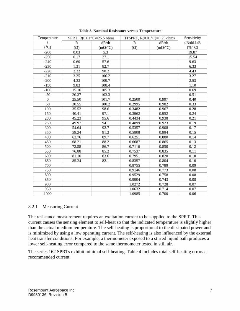
3.2 Resistance Measurement
The series 162 thermometers can be used with any AC or DC four-terminal resistance bridge,digital multimeter, or other readout instrument. Since the indicated temperature is determinedfrom the measured resistance, the accuracy and resolution of the measurement equipment mustbe consistent with the desired uncertainty budget. The nominal resistance and sensitivity versustemperature for the 25.5 ohm and 0.25 ohm SPRTs are included in Table 3. This data can beused to convert resistance measurement uncertainty to equivalent units of temperature. Forexample, 0.1 mΩ at 500°C is equivalent to 1.2 m°C and 117.6 m°C for models 162CE and 162Krespectively.
Cc
tT
Red
Black
lead wires 4x
platinumresistor
shielding
Models 162CE and 162CG
lead wires 4x
platinumresistor
Model 162D
Cc
tT
Red
Black
lead wires 4x
platinumresistor
shielding
Model 162K
test lead
Rosemount Aerospace Inc.D9930136, Revision B
7
Table 3. Nominal Resistance versus Temperature
SPRT, R(0.01°C)=25.5 ohms HTSPRT, R(0.01°C)=0.25 ohmsTemperaturet
(°C)R
(Ω)dR/dt
(mΩ/°C)R
(Ω)dR/dt
(mΩ/°C)
SensitivitydR/dt∗ 1/R
(%/°C)-260 0.03 5.3 19.87-250 0.17 27.1 15.54-240 0.60 57.6 9.63-230 1.31 82.7 6.33-220 2.22 98.2 4.43-210 3.25 106.2 3.27-200 4.33 109.7 2.53-150 9.83 108.4 1.10-100 15.16 105.3 0.69-50 20.37 103.3 0.510 25.50 101.7 0.2500 0.997 0.40
50 30.55 100.2 0.2995 0.982 0.33100 35.52 98.6 0.3482 0.967 0.28150 40.41 97.1 0.3962 0.952 0.24200 45.23 95.6 0.4434 0.938 0.21250 49.97 94.1 0.4899 0.923 0.19300 54.64 92.7 0.5357 0.908 0.17350 59.24 91.2 0.5808 0.894 0.15400 63.76 89.7 0.6251 0.880 0.14450 68.21 88.2 0.6687 0.865 0.13500 72.58 86.7 0.7116 0.850 0.12550 76.88 85.2 0.7537 0.835 0.11600 81.10 83.6 0.7951 0.820 0.10650 85.24 82.1 0.8357 0.804 0.10700 0.8755 0.789 0.09750 0.9146 0.773 0.08800 0.9529 0.758 0.08850 0.9904 0.743 0.08900 1.0272 0.728 0.07950 1.0632 0.714 0.07
1000 1.0985 0.700 0.06
3.2.1 Measuring Current
The resistance measurement requires an excitation current to be supplied to the SPRT. Thiscurrent causes the sensing element to self-heat so that the indicated temperature is slightly higherthan the actual medium temperature. The self-heating is proportional to the dissipated power andis minimized by using a low operating current. The self-heating is also influenced by the externalheat transfer conditions. For example, a thermometer exposed to a stirred liquid bath produces alower self-heating error compared to the same thermometer tested in still air.
The series 162 SPRTs exhibit minimal self-heating. Table 4 includes total self-heating errors atrecommended current.
Rosemount Aerospace Inc.D9930136, Revision B
8
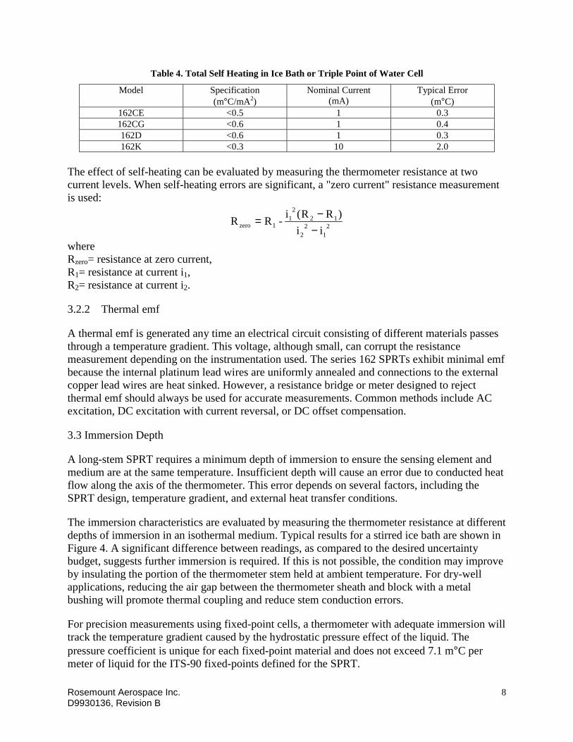
Table 4. Total Self Heating in Ice Bath or Triple Point of Water Cell
Model Specification(m°C/mA2)
Nominal Current(mA)
Typical Error(m°C)
162CE <0.5 1 0.3162CG <0.6 1 0.4162D <0.6 1 0.3162K <0.3 10 2.0
The effect of self-heating can be evaluated by measuring the thermometer resistance at twocurrent levels. When self-heating errors are significant, a "zero current" resistance measurementis used:
21
22
122
11zero ii
)RR(i-RR−−=
whereRzero= resistance at zero current,R1= resistance at current i1,R2= resistance at current i2.
3.2.2 Thermal emf
A thermal emf is generated any time an electrical circuit consisting of different materials passesthrough a temperature gradient. This voltage, although small, can corrupt the resistancemeasurement depending on the instrumentation used. The series 162 SPRTs exhibit minimal emfbecause the internal platinum lead wires are uniformly annealed and connections to the externalcopper lead wires are heat sinked. However, a resistance bridge or meter designed to rejectthermal emf should always be used for accurate measurements. Common methods include ACexcitation, DC excitation with current reversal, or DC offset compensation.
3.3 Immersion Depth
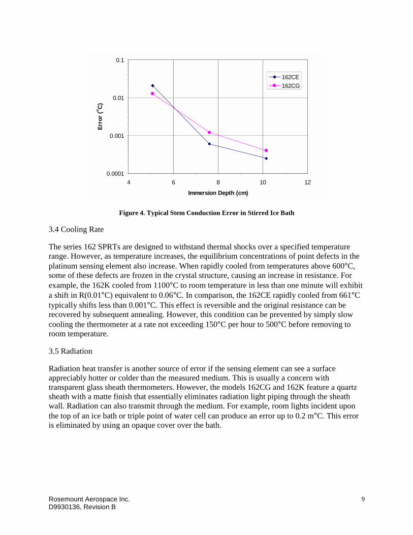
A long-stem SPRT requires a minimum depth of immersion to ensure the sensing element andmedium are at the same temperature. Insufficient depth will cause an error due to conducted heatflow along the axis of the thermometer. This error depends on several factors, including theSPRT design, temperature gradient, and external heat transfer conditions.
The immersion characteristics are evaluated by measuring the thermometer resistance at differentdepths of immersion in an isothermal medium. Typical results for a stirred ice bath are shown inFigure 4. A significant difference between readings, as compared to the desired uncertaintybudget, suggests further immersion is required. If this is not possible, the condition may improveby insulating the portion of the thermometer stem held at ambient temperature. For dry-wellapplications, reducing the air gap between the thermometer sheath and block with a metalbushing will promote thermal coupling and reduce stem conduction errors.
For precision measurements using fixed-point cells, a thermometer with adequate immersion willtrack the temperature gradient caused by the hydrostatic pressure effect of the liquid. Thepressure coefficient is unique for each fixed-point material and does not exceed 7.1 m°C permeter of liquid for the ITS-90 fixed-points defined for the SPRT.
Rosemount Aerospace Inc.D9930136, Revision B
9
Figure 4. Typical Stem Conduction Error in Stirred Ice Bath
3.4 Cooling Rate
The series 162 SPRTs are designed to withstand thermal shocks over a specified temperaturerange. However, as temperature increases, the equilibrium concentrations of point defects in theplatinum sensing element also increase. When rapidly cooled from temperatures above 600°C,some of these defects are frozen in the crystal structure, causing an increase in resistance. Forexample, the 162K cooled from 1100°C to room temperature in less than one minute will exhibita shift in R(0.01°C) equivalent to 0.06°C. In comparison, the 162CE rapidly cooled from 661°Ctypically shifts less than 0.001°C. This effect is reversible and the original resistance can berecovered by subsequent annealing. However, this condition can be prevented by simply slowcooling the thermometer at a rate not exceeding 150°C per hour to 500°C before removing toroom temperature.
3.5 Radiation
Radiation heat transfer is another source of error if the sensing element can see a surfaceappreciably hotter or colder than the measured medium. This is usually a concern withtransparent glass sheath thermometers. However, the models 162CG and 162K feature a quartzsheath with a matte finish that essentially eliminates radiation light piping through the sheathwall. Radiation can also transmit through the medium. For example, room lights incident uponthe top of an ice bath or triple point of water cell can produce an error up to 0.2 m°C. This erroris eliminated by using an opaque cover over the bath.
0.0001
0.001
0.01
0.1
4 6 8 10 12
Immersion Depth (cm)
Erro
r (o C)
162CE162CG
Rosemount Aerospace Inc.D9930136, Revision B
10
4. CALIBRATION
4.1 General
The series 162 SPRT must be calibrated before it can be used for accurate temperaturemeasurement. Calibration consists of measuring the thermometer resistance at a series of knowntemperatures and fitting the results with an interpolation equation. The calibration temperaturescan be fixed points with assigned temperature values, such as reproducible freezing points,melting points, or triple points of pure materials. Alternatively, the thermometer can becalibrated by comparison against a SPRT with a known calibration. Prior to calibration, theSPRT must be fully annealed (see 5.1).
The ITS-90 prescribes calibration points and interpolation formula for specific temperatureranges. Approximations of the ITS-90, such as using fewer or different calibration points, arecommonly used to balance cost and accuracy constraints. The laboratory performing thecalibration is responsible for providing a description of the test method and statement ofuncertainty.
4.2 Resistance Ratio
The SPRT is calibrated in terms of resistance ratio. The ITS-90 defines the resistance ratio W(t)as the ratio of resistance R(t) at temperature t and the resistance R(0.01°C) at the triple point ofwater:
W(t)=R(t)/R(0.01°C)
Using resistance ratio reduces system level errors and simplifies the calibration. For example, theW(t) is essentially independent of the ohm value if both R(t) and R(0.01°C) are measured withthe same resistance bridge. This minimizes errors caused by differences in equipment and ohmvalue maintained by the user and calibration laboratory. In addition, metallurgical changes of theplatinum wire affect the R(t) more than W(t). The superior stability of W(t) improves accuracyand extends the time interval between calibrations. Finally, SPRTs exhibit similar W(t)characteristics. The deviations between two thermometers or a reference function can bedescribed with a simple equation; the basis for the ITS-90 interpolation formula.
4.3 Triple Point of Water
The triple point of water (TPW) is a state where ice, water, and water vapor coexist in thermalequilibrium. The TPW is a defining fixed point on the ITS-90 and has an assigned temperaturevalue of 0.01°C. The R(0.01°C) is an important measurement for determining the resistance ratioW(t) and is a common benchmark for tracking the SPRT stability. Measuring the R(0.01°C)locally is the only way to take full advantage of a W(t) calibration and also provides a usefulcheck for validating measurements.
Rosemount Aerospace Inc.D9930136, Revision B
11
The best way to determine R(0.01°C) is with a TPW cell. These cells are commercially availableand typically have uncertainty less than 0.2 m°C. Alternatively, the R(0.01°C) may beapproximated from the ice-point:
C)/0.99996 R(0C) R(0.01 oo ≅
However, it is difficult to prepare and use an ice bath with uncertainty better than 2 m°C.
4.4 Interval
SPRTs are typically calibrated on intervals between six months and two years, depending onuncertainty budget and conditions of use. Thermometers used at temperatures above 500°C orsubjected to rough treatment are more susceptible to drift and usually require more frequentrecalibrations than other applications. Although a fixed calibration interval is convenient, it isgenerally more cost effective to evaluate and define an interval that meets the user's cost andaccuracy goals. Using historic calibration data provides rationale for establishing the calibrationinterval.
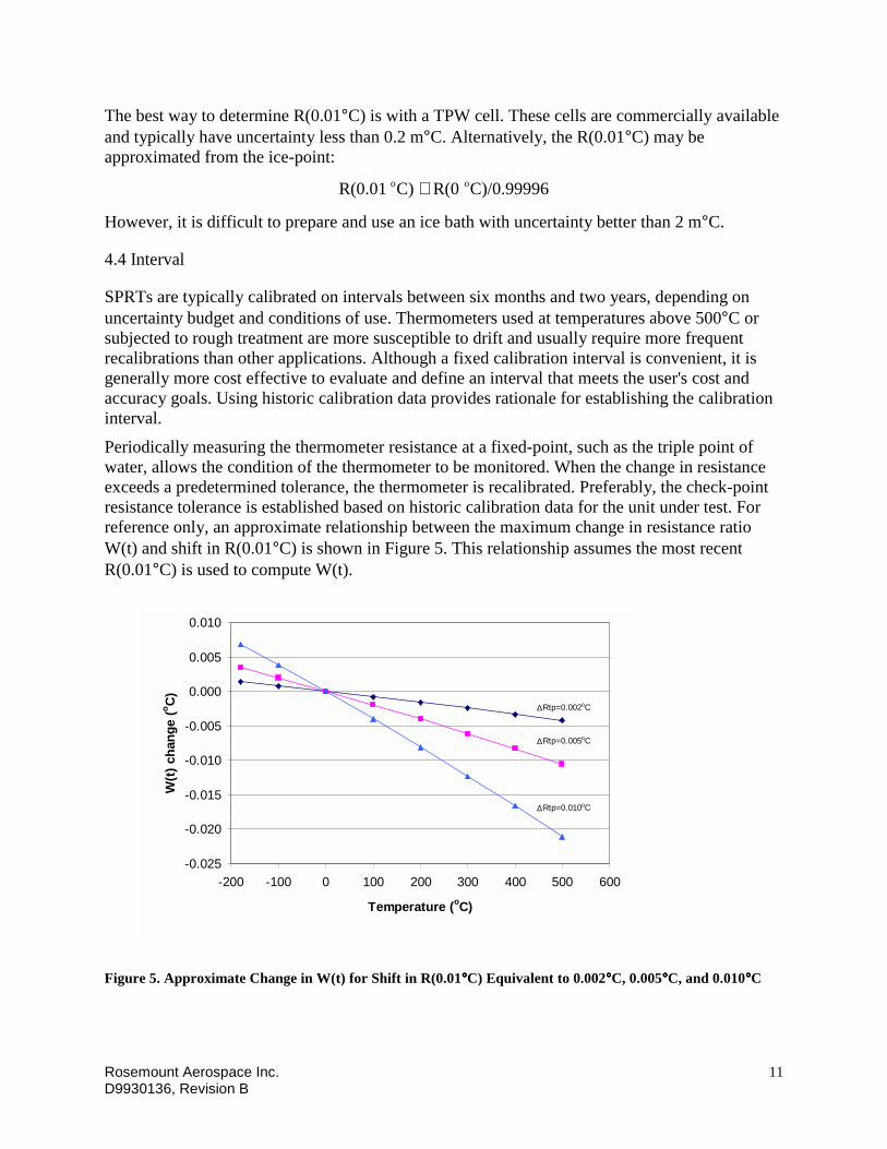
Periodically measuring the thermometer resistance at a fixed-point, such as the triple point ofwater, allows the condition of the thermometer to be monitored. When the change in resistanceexceeds a predetermined tolerance, the thermometer is recalibrated. Preferably, the check-pointresistance tolerance is established based on historic calibration data for the unit under test. Forreference only, an approximate relationship between the maximum change in resistance ratioW(t) and shift in R(0.01°C) is shown in Figure 5. This relationship assumes the most recentR(0.01°C) is used to compute W(t).
Figure 5. Approximate Change in W(t) for Shift in R(0.01°°°°C) Equivalent to 0.002°°°°C, 0.005°°°°C, and 0.010°°°°C
-0.025
-0.020
-0.015
-0.010
-0.005
0.000
0.005
0.010
-200 -100 0 100 200 300 400 500 600
Temperature (oC)
W(t)
cha
nge
(o C)
∆Rtp=0.010oC
∆Rtp=0.005oC
∆Rtp=0.002oC
Rosemount Aerospace Inc.D9930136, Revision B
12
4.5 Schedules
The thermometer is suitable for calibration over all or part of the specified temperature range.Rosemount Aerospace offers several fixed-point and comparison calibration schedules traceableto the NIST (see Price List P2710). Alternatively, the thermometer may be submitted directly tothe NIST or similar standards laboratory.
5. MAINTENANCE
5.1 Annealing
The SPRT is calibrated with the sensing element fully annealed. During transportation andhandling, the platinum wire can become strained, causing R(0.01°C) and resistance ratio W(t) tochange (see Figure 5). Subjecting the thermometer to elevated temperatures restores the platinumto a stable, strain-free state.
The annealing procedure requires a high temperature furnace and a method of checking thethermometer resistance at a fixed temperature between heat treatments. The triple point of wateror ice-point are common check temperatures. The procedure is summarized below.
- Measure resistance at check-point temperature.- Heat soak thermometer at recommended annealing temperature in Table 5 (see 2.3.3
for precautions related to quartz sheath thermometers).- Slow cool thermometer if applicable (see 3.4).- Measure resistance at check-point temperature.- Repeat procedure until the thermometer reaches desired stability and continues to
exhibit recovery (decreasing resistance).
The required annealing time varies depending on the condition of the thermometer. Limit theinitial soak to 2 to 4 hours to assess the recovery rate. Subsequent heat soak times can beextended but should not exceed 24 hours between check-point measurements.
CAUTION: PROLONGED HEATING AT MAXIMUM SPECIFIED TEMPERATURE MAYSHORTEN THE LIFE OF THE THERMOMETER. THE ANNEALING TIMESHOULD BE BASED ON ACHIEVING STABILITY, NOT A PREVIOUSLYANNEALED RESISTANCE VALUE. USUALLY ONLY A PORTION OF THERESISTANCE SHIFT IS RECOVERED SINCE STRAIN CAN CAUSE APERMANENT DIMENSIONAL CHANGE IN THE WIRE.
Because of the limited temperature capability of the capsule SPRT, the model 162D is usuallynot annealed before recalibrating. However, a severely strained element will exhibit somerecovery at maximum temperature of 250°C.
Rosemount Aerospace Inc.D9930136, Revision B
13
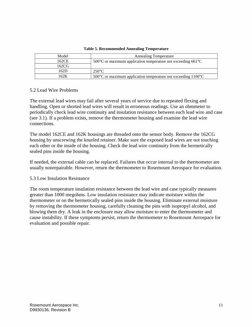
Table 5. Recommended Annealing Temperature
Model Annealing Temperature162CE162CG
500°C or maximum application temperature not exceeding 661°C
162D 250°C162K 500°C or maximum application temperature not exceeding 1100°C
5.2 Lead Wire Problems
The external lead wires may fail after several years of service due to repeated flexing andhandling. Open or shorted lead wires will result in erroneous readings. Use an ohmmeter toperiodically check lead wire continuity and insulation resistance between each lead wire and case(see 3.1). If a problem exists, remove the thermometer housing and examine the lead wireconnections.
The model 162CE and 162K housings are threaded onto the sensor body. Remove the 162CGhousing by unscrewing the knurled retainer. Make sure the exposed lead wires are not touchingeach other or the inside of the housing. Check the lead wire continuity from the hermeticallysealed pins inside the housing.
If needed, the external cable can be replaced. Failures that occur internal to the thermometer areusually nonrepairable. However, return the thermometer to Rosemount Aerospace for evaluation.
5.3 Low Insulation Resistance
The room temperature insulation resistance between the lead wire and case typically measuresgreater than 1000 megohms. Low insulation resistance may indicate moisture within thethermometer or on the hermetically sealed pins inside the housing. Eliminate external moistureby removing the thermometer housing, carefully cleaning the pins with isopropyl alcohol, andblowing them dry. A leak in the enclosure may allow moisture to enter the thermometer andcause instability. If these symptoms persist, return the thermometer to Rosemount Aerospace forevaluation and possible repair.
Rosemount Aerospace Inc.D9930136, Revision B
14
6. RETURN OF HARDWARE
The thermometer should be shipped in its protective storage case and wood crate. The storagecase should be surrounded by 8 to 10 cm (3 to 4 inches) of soft insulation to cushion thethermometer against mechanical shock. The cover of the crate should be attached with screws; anailed cover is not acceptable.
Thermometers returned for recalibration or repair, whether in or out of warranty, should beshipped prepaid to:
A letter that contains the following information should accompany the thermometer:
- Company name and address- Buyer's name and phone number- Technical contact name and phone number- Description of problem or calibration service requested- A purchase order for non-warranty service- Return shipping instructions
Fax: (802) 863-8125Phone: ( 802) 863-8050Colchester, VT 05446158 Brentwood Drive, Unit 4Isotech North America
Rosemount Aerospace Inc.D9930136, Revision B
15
7. SUGGESTED READING
The following publications contain useful information on SPRTs and related calibrations.
- H. Preston-Thomas, "The International Temperature Scale of 1990 (ITS-90),"Metrologia, Vol. 27, pp. 3-10, (1990). For errata see ibid., Vol. 27, p. 107, (1990).
- B. W. Mangum and G. T. Furukawa, "Guidelines for Realizing the InternationalTemperature Scale of 1990 (ITS-90)," NIST Technical Note 1265, (1990).
- H. Preston-Thomas, P. Bloembergen, and T. J. Quin, Supplementary Information forthe International Temperature Scale of 1990, Bureau International des Poids etMeasures, (1990).
- G. F. Strouse and W. L. Tew, "Assessment of Uncertainties of Calibration ofResistance Thermometers at the National Institute of Standards and Technology,"NISTIR 5319, (1994)
- J. L. Riddle, G. T. Furukawa, and H. H. Plumb, "Platinum Resistance Thermometry,"NBS Monograph 126, (1973).
- Temperature: Its Measurement and Control in Science and Industry, J. F. Schooley,ed., Vol. 6, American Institute of Physics, New York, (1992).
- Temperature: Its Measurement and Control in Science and Industry, J. F. Schooley,ed., Vol. 5, American Institute of Physics, New York, (1982).
- Standard Guide for Use of Water Triple Point Cells, E 1750, Annual Book of ASTMStandards, Vol. 14.03
- Standard Guide for Use of Freezing-Point Cells for Reference Temperatures, E 1502,Annual Book of ASTM Standards, Vol. 14.03
- Standard Practice for Preparation and Use of an Ice-Point Bath as a ReferenceTemperature, E 563, Annual Book of ASTM Standards, Vol. 14.03
Rosemount Aerospace Inc.D9930136, Revision B A-1
APPENDIX A
Specification Control Drawing