Embed Size (px)
Citation preview
5698 Working Standard Platinum Resistance Thermometer
2004, Rev. 1, 4/11© 2004 - 2011 Fluke Corporation. All rights reserved. Specifications subject to change without notice.
Users Guide
All product names are trademarks of their respective companies.
Limited Warranty & Limitation of LiabilityEach Fluke product is warranted to be free from defects in material and workmanship under normal use and service. The warranty period is one year and begins on the date of shipment. Parts, product repairs, and services are warranted for 90 days. This warranty extends only to the original buyer or end-user customer of a Fluke authorized reseller, and does not apply to fuses, disposable batteries, or to any product which, in Fluke’s opinion, has been misused, altered, neglected, contaminated, or damaged by accident or abnormal conditions of operation or handling. Fluke warrants that software will operate substantially in accordance with its functional specifications for 90 days and that it has been properly recorded on non-defective media. Fluke does not warrant that software will be error free or operate without interruption.
Fluke authorized resellers shall extend this warranty on new and unused products to end-user customers only but have no authority to extend a greater or different warranty on behalf of Fluke. Warranty support is available only if product is purchased through a Fluke authorized sales outlet or Buyer has paid the applicable international price. Fluke reserves the right to invoice Buyer for importation costs of repair/replacement parts when product purchased in one country is submitted for repair in another country.
Fluke’s warranty obligation is limited, at Fluke’s option, to refund of the purchase price, free of charge repair, or replacement of a defective product which is returned to a Fluke authorized service center within the warranty period.
To obtain warranty service, contact your nearest Fluke authorized service center to obtain return authorization information, then send the product to that service center, with a description of the difficulty, postage and insurance prepaid (FOB Destination). Fluke assumes no risk for damage in transit. Following warranty repair, the product will be returned to Buyer, transportation prepaid (FOB Destination). If Fluke determines that failure was caused by neglect, misuse, contamination, alteration, accident, or abnormal condition of operation or handling, including overvoltage failures caused by use outside the product’s specified rating, or normal wear and tear of mechanical components, Fluke will provide an estimate of repair costs and obtain authorization before commencing the work. Following repair, the product will be returned to the Buyer transportation prepaid and the Buyer will be billed for the repair and return transportation charges (FOB Shipping Point).
THIS WARRANTY IS BUYER’S SOLE AND EXCLUSIVE REMEDY AND IS IN LIEU OF ALL OTHER WARRANTIES, EXPRESS OR IMPLIED, INCLUDING BUT NOT LIMITED TO ANY IMPLIED WARRANTY OF MERCHANTABILITY OR FITNESS FOR A PARTICULAR PURPOSE. FLUKE SHALL NOT BE LIABLE FOR ANY SPECIAL, INDIRECT, INCIDENTAL, OR CONSEQUENTIAL DAMAGES OR LOSSES, INCLUDING LOSS OF DATA, ARISING FROM ANY CAUSE OR THEORY.
Since some countries or states do not allow limitation of the term of an implied warranty, or exclusion or limitation of incidental or consequential damages, the limitations and exclusions of this warranty may not apply to every buyer. If any provision of this Warranty is held invalid or unenforceable by a court or other decision-maker of competent jurisdiction, such holding will not affect the validity or enforceability of any other provision.
Fluke Corporation Fluke Europe B.V. P.O. Box 9090 P.O. Box 1186 Everett, WA 98206-9090 5602 BD Eindhoven U.S.A. The Netherlands
11/99
i
Table of Contents
Title Page
Introduction .........................................................................................................................1General ............................................................................................................................1Application ......................................................................................................................1Calibration ......................................................................................................................1Calibration Options .........................................................................................................1Recalibration ...................................................................................................................2
Before You Start ..................................................................................................................2Symbols Used .................................................................................................................2Safety Information ..........................................................................................................2Verifying SPRT Accuracy ...............................................................................................4How to Contact Fluke .....................................................................................................4Return Procedure ............................................................................................................5
Specifications ......................................................................................................................5Construction ....................................................................................................................5Electrical Circuit .............................................................................................................6
Installation ..........................................................................................................................6Environmental Issues ......................................................................................................6Mounting .........................................................................................................................6Lead Wire Identification .................................................................................................7
Care and Handling Guidelines ..........................................................................................10SPRT Care .....................................................................................................................10SPRT Handling Guidelines ........................................................................................... 11Metal Ion Contamination of SPRTs .............................................................................. 11Devitrification of Fused Silica Glass ............................................................................12
Operation ..........................................................................................................................12Comparison Calibration of Other Instruments ..............................................................12Measuring Current ........................................................................................................13Immersion Requirements ..............................................................................................13Thermal EMF ................................................................................................................13Cooling Rates at High Temperatures ............................................................................14
Accessories .......................................................................................................................14Case ...............................................................................................................................14

5698Users Guide
ii
SPRT Termination .........................................................................................................14 Troubleshooting ................................................................................................................15

iii
List of Tables
Table TitleTable 1. International Electrical Symbols ...............................................................................................2Table 2. Specifications ............................................................................................................................5Table 3. Suggested Drive Current .........................................................................................................13Table 4. 5698 Troubleshooting ............................................................................................................15
Page

5698Users Guide
iv
v
List of Figures
Figure Title PageFigure 1. 5698 Working Standard Platinum Resistance Thermometer ...................................................1Figure 2. Standard Dimensions ...............................................................................................................6Figure 3. Liquid Bath Installation ...........................................................................................................7Figure 4. Water Triple Point Cell in an Ice Bath Dewar .........................................................................8Figure 5. Fluke 9114 Metrology Furnace with SPRT in Fixed Point Cell ..............................................9Figure 6. SPRT Circuit Schematic ........................................................................................................10

5698Users Guide
vi
1
Introduction
GeneralThe Fluke Working Standard Platinum Resistance Thermometer (SPRT) is designed to be the best primary standard interpolating instrument converting resistance to temperature. With full calibration options, ITS-90 coefficients can be used with your 1594A/1595A Super-Thermometer, 1560 Black Stack, or the 1529 Chub-E4 Thermometer readout. With drift rate typically around ±3 mK, this SPRT gets you from –200 °C up to 670 °C.Each SPRT is carefully annealed at the appropriate temperatures and precisely tested for stability. Convection prevention discs are used to reduce stem errors caused by thermal radiation. The sensing element is fabricated using high purity platinum wire wound in a strain free design on a fused silica cross frame. A fused silica sheath is pressure sealed with a special argon/oxygen mixed gas and fitted with a terminal box handle with a strain relieved connection to the four wire cable. Gold plated spade lugs terminate the wires.
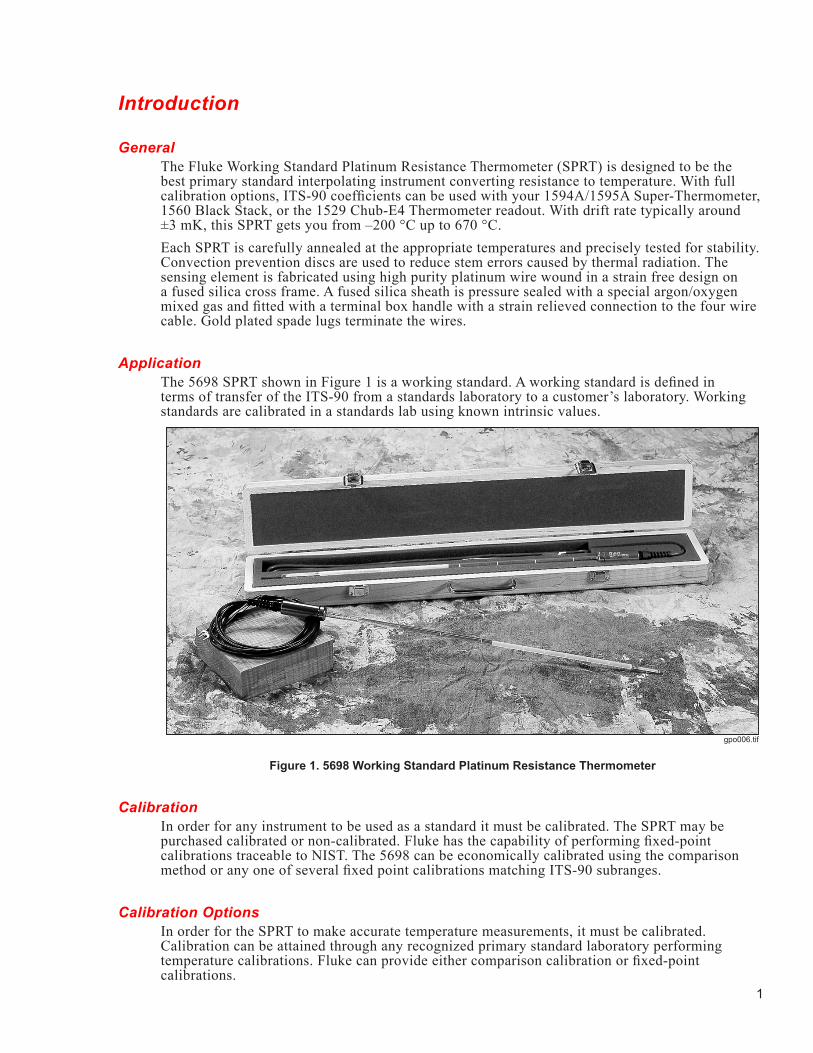
ApplicationThe 5698 SPRT shown in Figure 1 is a working standard. A working standard is defined in terms of transfer of the ITS-90 from a standards laboratory to a customer’s laboratory. Working standards are calibrated in a standards lab using known intrinsic values.
gpo006.tif
Figure 1. 5698 Working Standard Platinum Resistance Thermometer
CalibrationIn order for any instrument to be used as a standard it must be calibrated. The SPRT may be purchased calibrated or non-calibrated. Fluke has the capability of performing fixed-point calibrations traceable to NIST. The 5698 can be economically calibrated using the comparison method or any one of several fixed point calibrations matching ITS-90 subranges.
Calibration OptionsIn order for the SPRT to make accurate temperature measurements, it must be calibrated. Calibration can be attained through any recognized primary standard laboratory performing temperature calibrations. Fluke can provide either comparison calibration or fixed-point calibrations.
5698Users Guide
2
RecalibrationThe recalibration of the SPRT should be scheduled according to the user’s company Quality Assurance requirements. Generally, an SPRT is used over a specific range. The SPRT should be calibrated over the range applicable to its use. The SPRT should only be calibrated over its full temperature range if it is used over its full range. For information on recalibrating your SPRT, contact Fluke for assistance (see “How to Contact Fluke”).
Before You Start
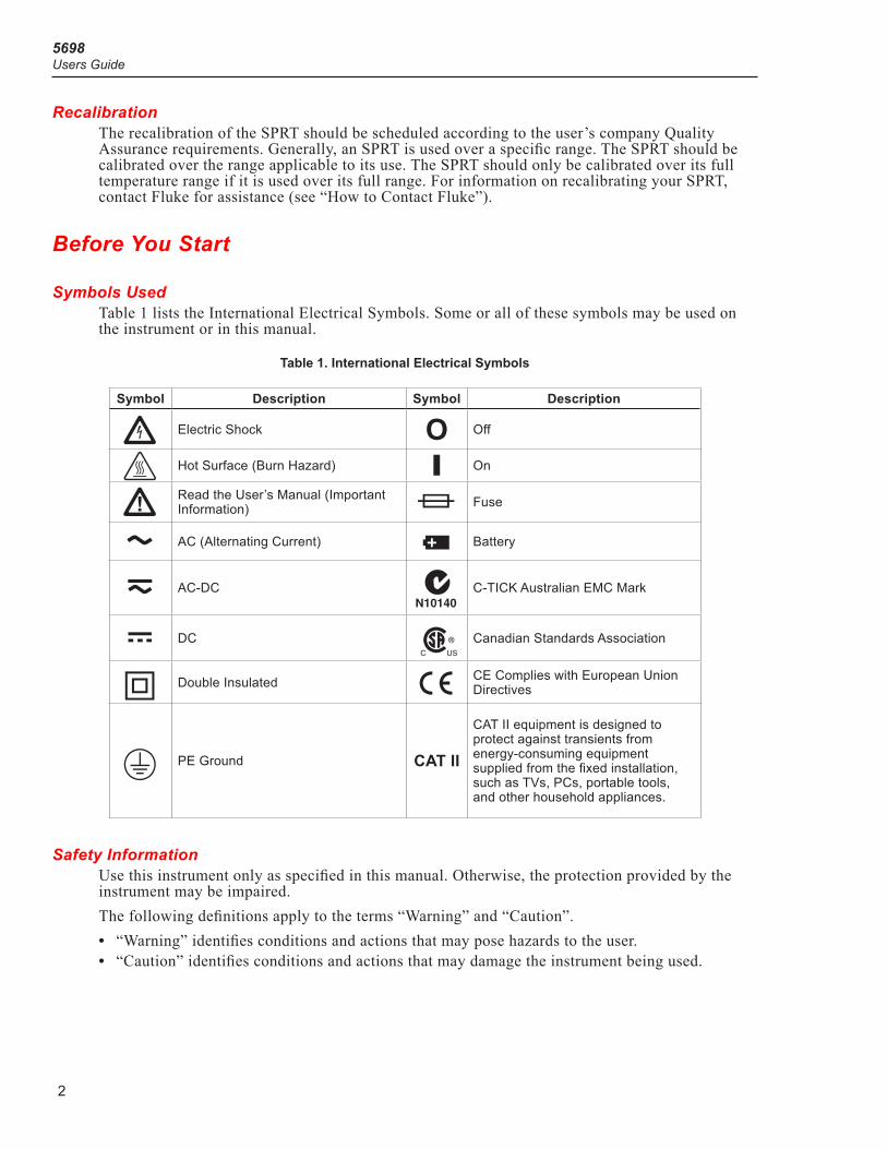
Symbols UsedTable 1 lists the International Electrical Symbols. Some or all of these symbols may be used on the instrument or in this manual.
Table 1. International Electrical Symbols
Symbol Description Symbol Description
X Electric Shock O Off
: Hot Surface (Burn Hazard) I On
W Read the User’s Manual (Important Information) I Fuse
B AC (Alternating Current) M Battery
D AC-DC ; C-TICK Australian EMC Mark
F DC ) Canadian Standards Association
T Double Insulated P CE Complies with European Union Directives
. PE Ground CAT II
CAT II equipment is designed to protect against transients from energy-consuming equipment supplied from the fixed installation, such as TVs, PCs, portable tools, and other household appliances.
Safety InformationUse this instrument only as specified in this manual. Otherwise, the protection provided by the instrument may be impaired.The following definitions apply to the terms “Warning” and “Caution”.• “Warning” identifies conditions and actions that may pose hazards to the user.• “Caution” identifies conditions and actions that may damage the instrument being used.
Working Standard Platinum Resistance ThermometerBefore You Start
3
Warning W
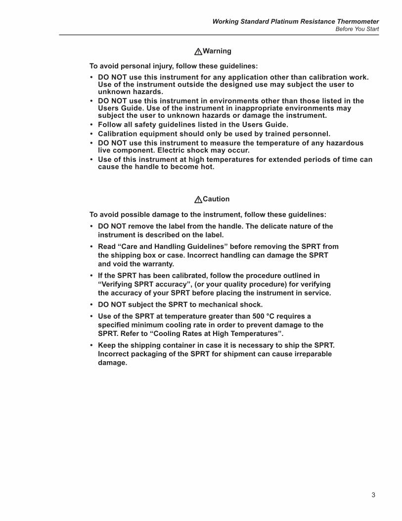
To avoid personal injury, follow these guidelines:• DO NOT use this instrument for any application other than calibration work.
Use of the instrument outside the designed use may subject the user to unknown hazards.
• DO NOT use this instrument in environments other than those listed in the Users Guide. Use of the instrument in inappropriate environments may subject the user to unknown hazards or damage the instrument.
• Follow all safety guidelines listed in the Users Guide.• Calibration equipment should only be used by trained personnel. • DO NOT use this instrument to measure the temperature of any hazardous
live component. Electric shock may occur.• Use of this instrument at high temperatures for extended periods of time can
cause the handle to become hot.
Caution W
To avoid possible damage to the instrument, follow these guidelines:• DO NOT remove the label from the handle. The delicate nature of the
instrument is described on the label.• Read “Care and Handling Guidelines” before removing the SPRT from
the shipping box or case. Incorrect handling can damage the SPRT and void the warranty.
• If the SPRT has been calibrated, follow the procedure outlined in “Verifying SPRT accuracy”, (or your quality procedure) for verifying the accuracy of your SPRT before placing the instrument in service.
• DO NOT subject the SPRT to mechanical shock.• Use of the SPRT at temperature greater than 500 °C requires a specifiedminimumcoolingrateinordertopreventdamagetotheSPRT. Refer to “Cooling Rates at High Temperatures”.
• Keep the shipping container in case it is necessary to ship the SPRT. Incorrect packaging of the SPRT for shipment can cause irreparable damage.
5698Users Guide
4
Verifying SPRT Accuracy
Caution W
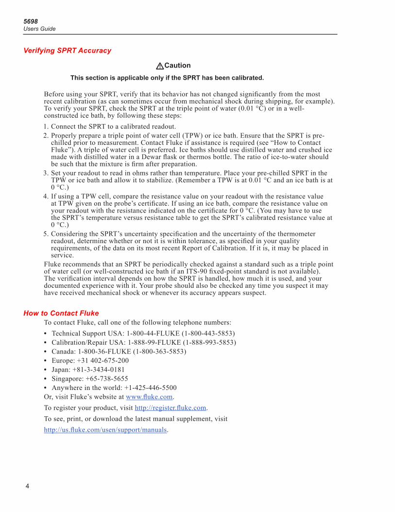
This section is applicable only if the SPRT has been calibrated.
Before using your SPRT, verify that its behavior has not changed significantly from the most recent calibration (as can sometimes occur from mechanical shock during shipping, for example). To verify your SPRT, check the SPRT at the triple point of water (0.01 °C) or in a well-constructed ice bath, by following these steps:1. Connect the SPRT to a calibrated readout.2. Properly prepare a triple point of water cell (TPW) or ice bath. Ensure that the SPRT is pre-
chilled prior to measurement. Contact Fluke if assistance is required (see “How to Contact Fluke”). A triple of water cell is preferred. Ice baths should use distilled water and crushed ice made with distilled water in a Dewar flask or thermos bottle. The ratio of ice-to-water should be such that the mixture is firm after preparation.
3. Set your readout to read in ohms rather than temperature. Place your pre-chilled SPRT in the TPW or ice bath and allow it to stabilize. (Remember a TPW is at 0.01 °C and an ice bath is at 0 °C.)
4. If using a TPW cell, compare the resistance value on your readout with the resistance value at TPW given on the probe’s certificate. If using an ice bath, compare the resistance value on your readout with the resistance indicated on the certificate for 0 °C. (You may have to use the SPRT’s temperature versus resistance table to get the SPRT’s calibrated resistance value at 0 °C.)
5. Considering the SPRT’s uncertainty specification and the uncertainty of the thermometer readout, determine whether or not it is within tolerance, as specified in your quality requirements, of the data on its most recent Report of Calibration. If it is, it may be placed in service.
Fluke recommends that an SPRT be periodically checked against a standard such as a triple point of water cell (or well-constructed ice bath if an ITS-90 fixed-point standard is not available). The verification interval depends on how the SPRT is handled, how much it is used, and your documented experience with it. Your probe should also be checked any time you suspect it may have received mechanical shock or whenever its accuracy appears suspect.
How to Contact FlukeTo contact Fluke, call one of the following telephone numbers:• Technical Support USA: 1-800-44-FLUKE (1-800-443-5853)• Calibration/Repair USA: 1-888-99-FLUKE (1-888-993-5853)• Canada: 1-800-36-FLUKE (1-800-363-5853)• Europe: +31 402-675-200• Japan: +81-3-3434-0181• Singapore: +65-738-5655• Anywhere in the world: +1-425-446-5500Or, visit Fluke’s website at www.fluke.com.To register your product, visit http://register.fluke.com.To see, print, or download the latest manual supplement, visithttp://us.fluke.com/usen/support/manuals.
Working Standard Platinum Resistance ThermometerSpecifications
5
Return Procedure�Not�
Call Flukt fNr a rtourn auohNrizaoiNn priNr oN shipping oht SPRT.
We recommend that a good TPW measurement be made before returning the SPRT to ensure stability. Extreme care must be taken when shipping an SPRT. Place the SPRT in the factory provided protective storage case. Be sure the case is latched securely. Place the protective case in the original manufacturer’s wooden shipping crate or wooden crate with similar dimensions (44.5 in x 11.75 in x 11.75 in). Place soft insulation on all sides of the crate to cushion the SPRT against mechanical shock. The cover of the crate should be attached with screws. We recommend that you label the crate as extremely fragile. Whether the SPRT is returned for repair or warranty, please include a letter containing the following information:• Description of the faulty operation and circumstances of failure.• Complete shipping instructions for the return of the thermometer to the customer.
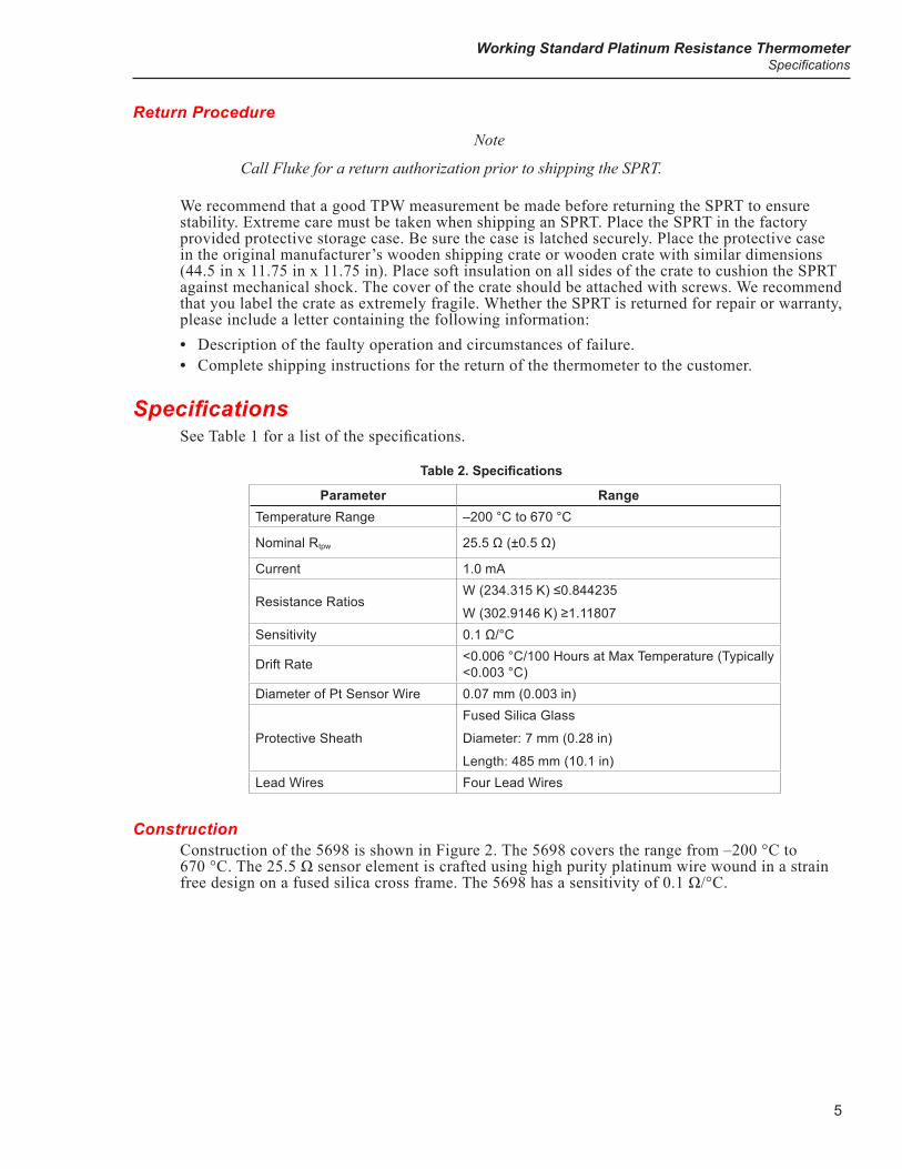
SpecificationsSee Table 1 for a list of the specifications.
Table 2. Specifications
Parameter RangeTemperature Range –200 °C to 670 °C
Nominal Rtpw 25.5 Ω (±0.5 Ω)
Current 1.0 mA
Resistance RatiosW (234.315 K) ≤0.844235
W (302.9146 K) ≥1.11807Sensitivity 0.1 Ω/°C
Drift Rate <0.006 °C/100 Hours at Max Temperature (Typically <0.003 °C)
Diameter of Pt Sensor Wire 0.07 mm (0.003 in)
Protective Sheath
Fused Silica Glass
Diameter: 7 mm (0.28 in)
Length: 485 mm (10.1 in)Lead Wires Four Lead Wires
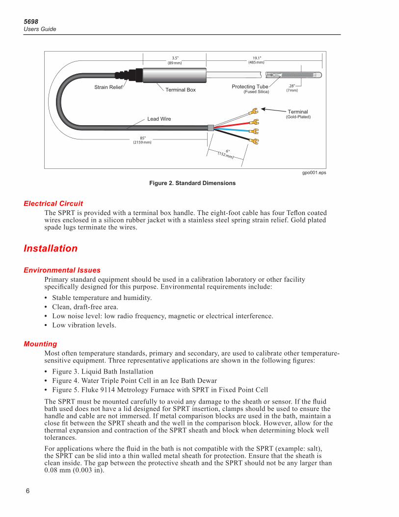
ConstructionConstruction of the 5698 is shown in Figure 2. The 5698 covers the range from –200 °C to 670 °C. The 25.5 Ω sensor element is crafted using high purity platinum wire wound in a strain free design on a fused silica cross frame. The 5698 has a sensitivity of 0.1 Ω/°C.
5698Users Guide
6
Terminal(Gold-Plated)
T erminal Box Protecting Tube(Fused Silica)
.28"(7mm)
85"(2159 mm)
Strain Relief
Lead Wire
19.1"(485 mm)
6"(152 mm)
3.5"(89 mm)
gpo001.eps
Figure 2. Standard Dimensions
Electrical CircuitThe SPRT is provided with a terminal box handle. The eight-foot cable has four Teflon coated wires enclosed in a silicon rubber jacket with a stainless steel spring strain relief. Gold plated spade lugs terminate the wires.
Installation
Environmental IssuesPrimary standard equipment should be used in a calibration laboratory or other facility specifically designed for this purpose. Environmental requirements include:• Stable temperature and humidity.• Clean, draft-free area.• Low noise level: low radio frequency, magnetic or electrical interference.• Low vibration levels.
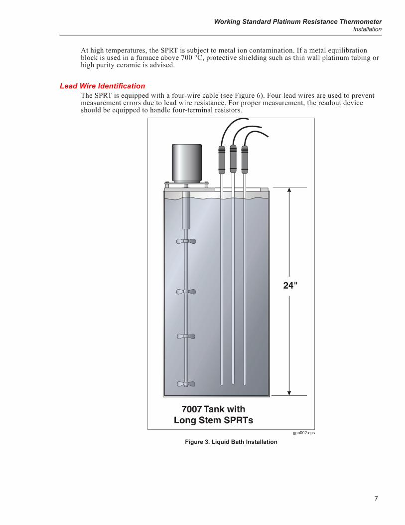
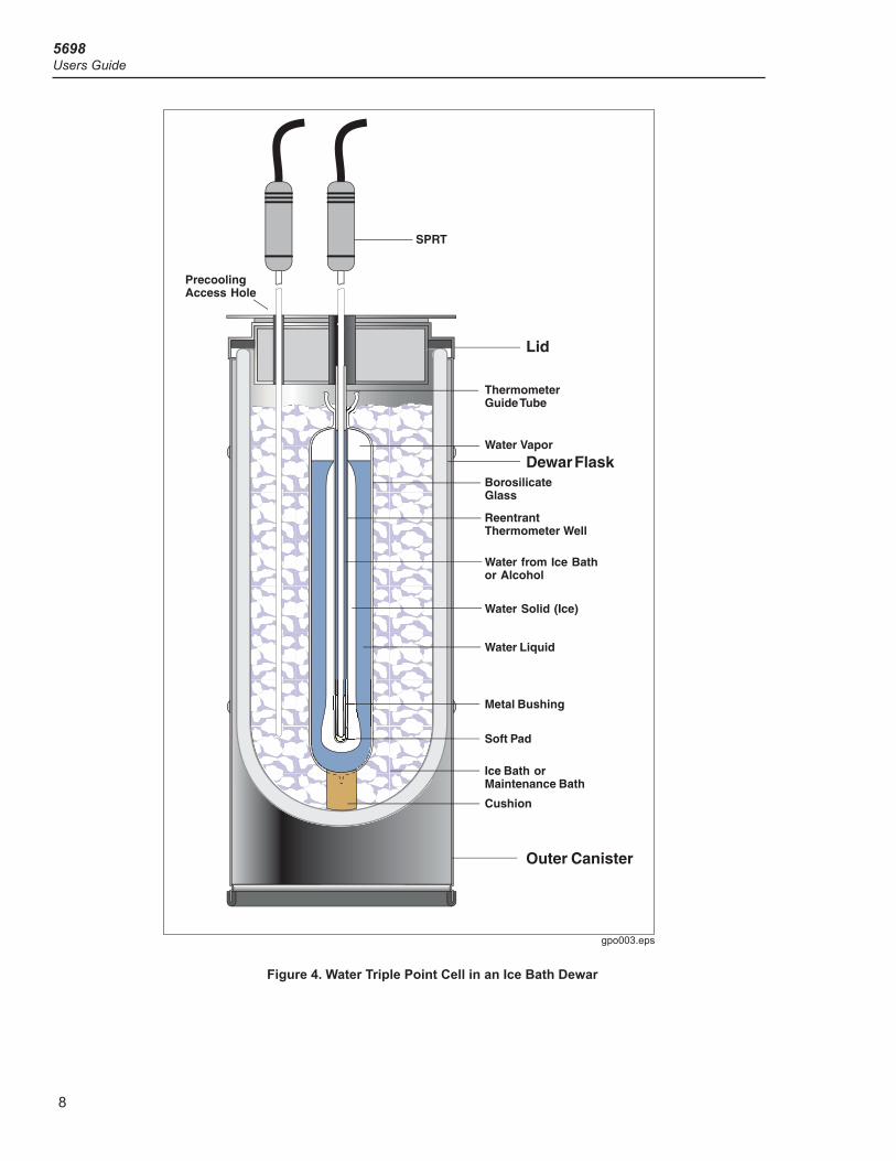
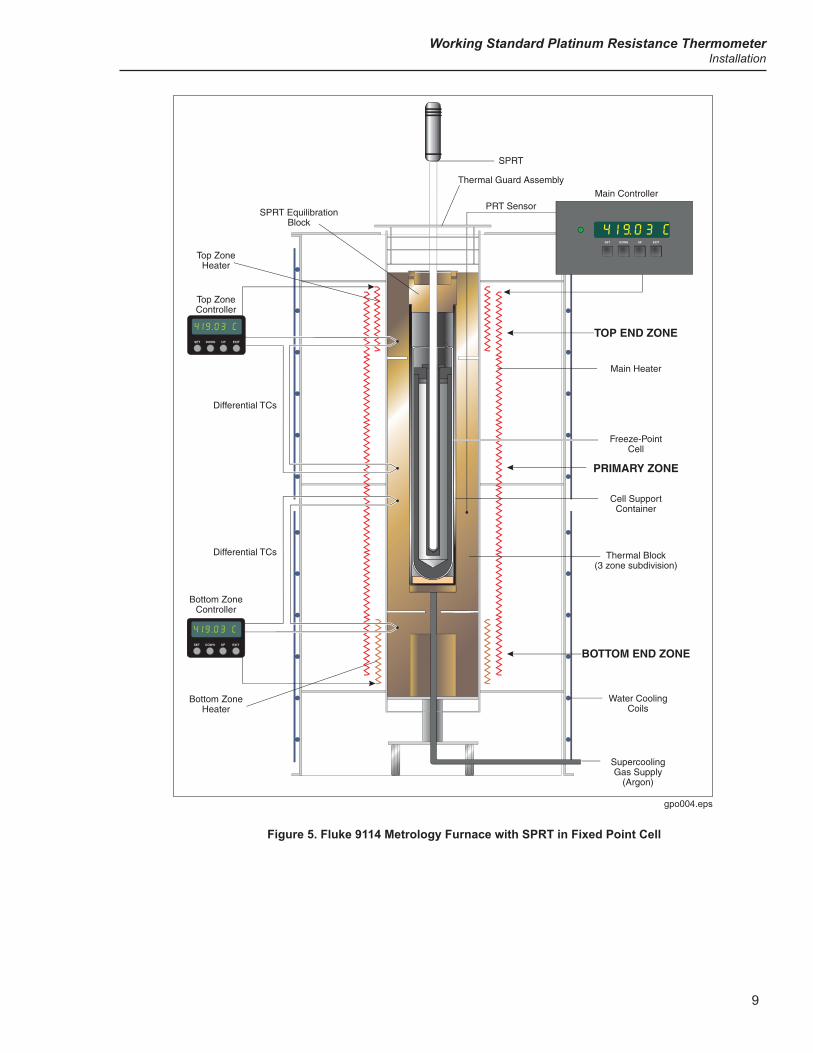
MountingMost often temperature standards, primary and secondary, are used to calibrate other temperature-sensitive equipment. Three representative applications are shown in the following figures:• Figure 3. Liquid Bath Installation• Figure 4. Water Triple Point Cell in an Ice Bath Dewar• Figure 5. Fluke 9114 Metrology Furnace with SPRT in Fixed Point CellThe SPRT must be mounted carefully to avoid any damage to the sheath or sensor. If the fluid bath used does not have a lid designed for SPRT insertion, clamps should be used to ensure the handle and cable are not immersed. If metal comparison blocks are used in the bath, maintain a close fit between the SPRT sheath and the well in the comparison block. However, allow for the thermal expansion and contraction of the SPRT sheath and block when determining block well tolerances.For applications where the fluid in the bath is not compatible with the SPRT (example: salt), the SPRT can be slid into a thin walled metal sheath for protection. Ensure that the sheath is clean inside. The gap between the protective sheath and the SPRT should not be any larger than 0.08 mm (0.003 in).
Working Standard Platinum Resistance ThermometerInstallation
7
At high temperatures, the SPRT is subject to metal ion contamination. If a metal equilibration block is used in a furnace above 700 °C, protective shielding such as thin wall platinum tubing or high purity ceramic is advised.
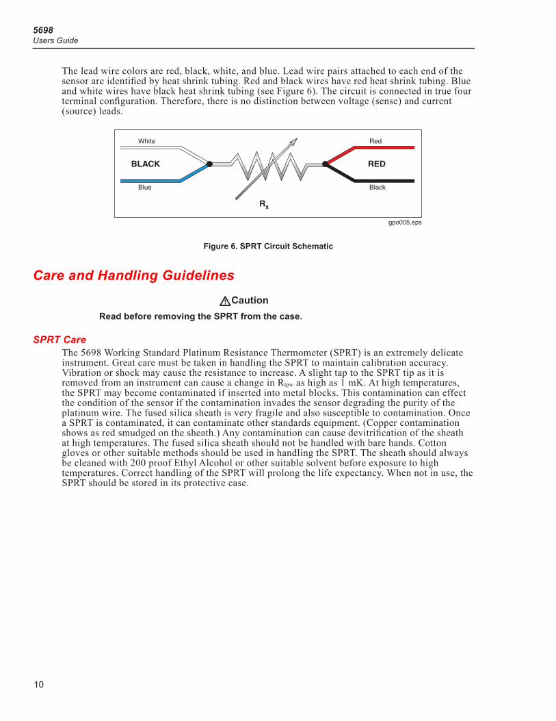
Lead Wire IdentificationThe SPRT is equipped with a four-wire cable (see Figure 6). Four lead wires are used to prevent measurement errors due to lead wire resistance. For proper measurement, the readout device should be equipped to handle four-terminal resistors.
gpo002.eps
Figure 3. Liquid Bath Installation
5698Users Guide
8
gpo003.eps
Figure 4. Water Triple Point Cell in an Ice Bath Dewar
Working Standard Platinum Resistance ThermometerInstallation
9
gpo004.eps
Figure 5. Fluke 9114 Metrology Furnace with SPRT in Fixed Point Cell
5698Users Guide
10
The lead wire colors are red, black, white, and blue. Lead wire pairs attached to each end of the sensor are identified by heat shrink tubing. Red and black wires have red heat shrink tubing. Blue and white wires have black heat shrink tubing (see Figure 6). The circuit is connected in true four terminal configuration. Therefore, there is no distinction between voltage (sense) and current (source) leads.
gpo005.eps
Figure 6. SPRT Circuit Schematic
Care and Handling GuidelinesCaution W
Read before removing the SPRT from the case.
SPRT CareThe 5698 Working Standard Platinum Resistance Thermometer (SPRT) is an extremely delicate instrument. Great care must be taken in handling the SPRT to maintain calibration accuracy. Vibration or shock may cause the resistance to increase. A slight tap to the SPRT tip as it is removed from an instrument can cause a change in Rtpw as high as 1 mK. At high temperatures, the SPRT may become contaminated if inserted into metal blocks. This contamination can effect the condition of the sensor if the contamination invades the sensor degrading the purity of the platinum wire. The fused silica sheath is very fragile and also susceptible to contamination. Once a SPRT is contaminated, it can contaminate other standards equipment. (Copper contamination shows as red smudged on the sheath.) Any contamination can cause devitrification of the sheath at high temperatures. The fused silica sheath should not be handled with bare hands. Cotton gloves or other suitable methods should be used in handling the SPRT. The sheath should always be cleaned with 200 proof Ethyl Alcohol or other suitable solvent before exposure to high temperatures. Correct handling of the SPRT will prolong the life expectancy. When not in use, the SPRT should be stored in its protective case.
Working Standard Platinum Resistance ThermometerCare and Handling Guidelines
11
SPRT Handling Guidelines1. Keep the SPRT as clean as possible. Always remove any fluid from the sheath as soon as
possible after taking the SPRT from a bath. Ensure that the fluid and SPRT have cooled sufficiently to prevent a safety hazard. To remove any possible contaminants, always wipe the sheath with ethyl alcohol or other solvent before submitting the SPRT to high temperatures.
2. Immerse the SPRT in the appropriate liquid for the temperature range. If a dry block is used, the well diameter should allow the SPRT to comfortably slip in and out without excess movement. For best results, immerse the SPRT as deep as possible to avoid “stem effect” (the temperature error caused by the conduction of heat away from the sensor). Do not submerge the handles.
3. Allow sufficient time for the SPRT to stabilize before making measurements. This allows for the best accuracy.
4. Use the correct drive current with the SPRT to prevent error in temperature or resistance.5. Anneal the SPRT at a temperature slightly higher than the maximum temperature at which the
thermometer will be used when it has been subjected to mechanical or temperature shock. The SPRT should also be annealed before calibration. The SPRT should be annealed at 675 °C.
6. Use the protective case provided or other protection when the thermometer is not in use.7. DO NOT subject the thermometer to any physical shock or vibration.8. DO NOT subject the thermometer to temperatures above the highest specified operating
temperature.9. DO NOT expose the thermometer’s handle or cables to extreme temperatures.
10. DO NOT submerge the handle or cable in liquids.
Metal Ion Contamination of SPRTsSince the acceptance of ITS-90, information has been accumulating about contamination of SPRTs. ITS-90 extended the range of the SPRT as an interpolation device and new problems manifested themselves. Metal ion contamination is one of the new problems and can start at approximately 700 °C.At high temperatures the lattice structure of most metals becomes open. This allows energetic metal ions to come off the surface, analogous to steam rising from hot water. Since the molecular activity increases with temperature, so does the amount of ion loss and the risk of contamination. Ion transfer occurs at different temperatures for different metals. Copper, nickel, iron, and manganese are metals that have been attributed to causing contamination. In addition, the fused silica lattice structure also becomes open at these high temperatures. This allows the fused silica to become transparent to these metal ions permitting the transfer of these ions from adjacent metal surfaces to the pure platinum wire of the SPRT sensor. The contaminated platinum behaves unpredictably, resulting in a loss of stability and calibration.Contamination can be spread by an “infected” SPRT to other primary standards analogous to a virus. Therefore, it is very important to avoid contamination as much as possible to ensure the longevity of the SPRT itself and to decrease the spread to other standards.Isolation of sensitive materials can prevent contamination. Pure platinum foil is being used by some experts to intercept the ions before they reach the SPRT. Silicon carbide is also used by some experts to shield the SPRT because it is less expensive than platinum foil. Information on contamination effects and prevention is still being gathered by experts in the field.
5698Users Guide
12
Devitrification of Fused Silica GlassDevitrification is a natural process with quartz materials. The fused silica is utilized in a glass (non-crystalline) state. The most stable state for fused silica is crystalline. Therefore, devitrification is the tendency of the fused silica to return to its most stable state. If the fused silica is kept extremely clean and free of contamination, devitrification occurs only at high temperatures. The process occurs more rapidly and at lower temperatures when the glass is contaminated by alkaline metals (Na, K, Mg, and Ca). The alkalis found in normal tap water can trigger the process.Removal of the devitrification is not practical as it requires drastic measures and is potentially dangerous to the instrument and/or the user.Devitrification starts with a dulling or opacity of the fused silica sheath. It develops into a rough and crumbling surface. Devitrification ultimately weakens the fused silica until it breaks or is otherwise no longer useful.The best cure for contamination and devitrification is prevention. Being aware of the causes and signs of contamination can help the user take the steps necessary to control contamination of the SPRT. Keep your SPRT clean and avoid contact with metals at temperatures above 700 °C.
OperationFor best results, be familiar with the operation of the calibration bath or furnace and the readout instrument. Be sure to follow the manufacturer’s instructions for the readout instrument and the calibration bath or furnace.
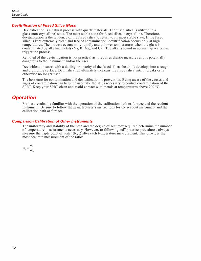
Comparison Calibration of Other InstrumentsThe uniformity and stability of the bath and the degree of accuracy required determine the number of temperature measurements necessary. However, to follow “good” practice procedures, always measure the triple point of water (Rtpw) after each temperature measurement. This provides the most accurate measurement of the ratio:
Wt = Rt Rtp
Working Standard Platinum Resistance ThermometerOperation
13
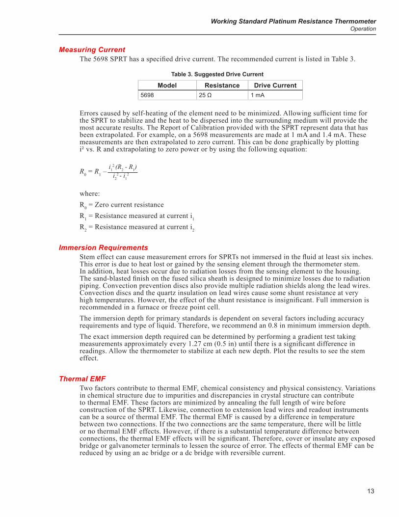
Measuring CurrentThe 5698 SPRT has a specified drive current. The recommended current is listed in Table 3.
Table 3. Suggested Drive Current
Model Resistance Drive Current5698 25 Ω 1 mA
Errors caused by self-heating of the element need to be minimized. Allowing sufficient time for the SPRT to stabilize and the heat to be dispersed into the surrounding medium will provide the most accurate results. The Report of Calibration provided with the SPRT represent data that has been extrapolated. For example, on a 5698 measurements are made at 1 mA and 1.4 mA. These measurements are then extrapolated to zero current. This can be done graphically by plotting i² vs. R and extrapolating to zero power or by using the following equation:
R0 = R1 – i12 (R2 - R1)i2
2 - i12
where:R0 = Zero current resistanceR1 = Resistance measured at current i1
R2 = Resistance measured at current i2
Immersion RequirementsStem effect can cause measurement errors for SPRTs not immersed in the fluid at least six inches. This error is due to heat lost or gained by the sensing element through the thermometer stem. In addition, heat losses occur due to radiation losses from the sensing element to the housing. The sand-blasted finish on the fused silica sheath is designed to minimize losses due to radiation piping. Convection prevention discs also provide multiple radiation shields along the lead wires. Convection discs and the quartz insulation on lead wires cause some shunt resistance at very high temperatures. However, the effect of the shunt resistance is insignificant. Full immersion is recommended in a furnace or freeze point cell.The immersion depth for primary standards is dependent on several factors including accuracy requirements and type of liquid. Therefore, we recommend an 0.8 in minimum immersion depth. The exact immersion depth required can be determined by performing a gradient test taking measurements approximately every 1.27 cm (0.5 in) until there is a significant difference in readings. Allow the thermometer to stabilize at each new depth. Plot the results to see the stem effect.
Thermal EMFTwo factors contribute to thermal EMF, chemical consistency and physical consistency. Variations in chemical structure due to impurities and discrepancies in crystal structure can contribute to thermal EMF. These factors are minimized by annealing the full length of wire before construction of the SPRT. Likewise, connection to extension lead wires and readout instruments can be a source of thermal EMF. The thermal EMF is caused by a difference in temperature between two connections. If the two connections are the same temperature, there will be little or no thermal EMF effects. However, if there is a substantial temperature difference between connections, the thermal EMF effects will be significant. Therefore, cover or insulate any exposed bridge or galvanometer terminals to lessen the source of error. The effects of thermal EMF can be reduced by using an ac bridge or a dc bridge with reversible current.
5698Users Guide
14
Cooling Rates at High TemperaturesThe equilibrium concentration of point defects in the pure platinum wire increase exponentially at higher temperatures. If a high cooling rate (example: removing a SPRT from a high temperature and cooling it to room temperature in less than a minute) occurs above 500 °C, some of the point defects in the platinum wire become trapped in the crystalline structure causing a slight increase in resistance. This slight increase in resistance can be reversed by annealing the SPRT. To avoid this problem, slowly cool the SPRT at a rate of roughly 150 °C/hour above 500 °C before removing to room temperature. The SPRT can be safely removed from an instrument at 500 °C or less and cooled to room temperature without concern for the cooling rate.
Accessories
CaseThe SPRTS are shipped in a protective case. The SPRT should be stored in this case when not in use. The SPRT should be shipped in this case when returning (see “Return Procedure”).
SPRT TerminationThe 5698 SPRT is terminated with gold plated lugs.
Working Standard Platinum Resistance ThermometerTroubleshooting
15
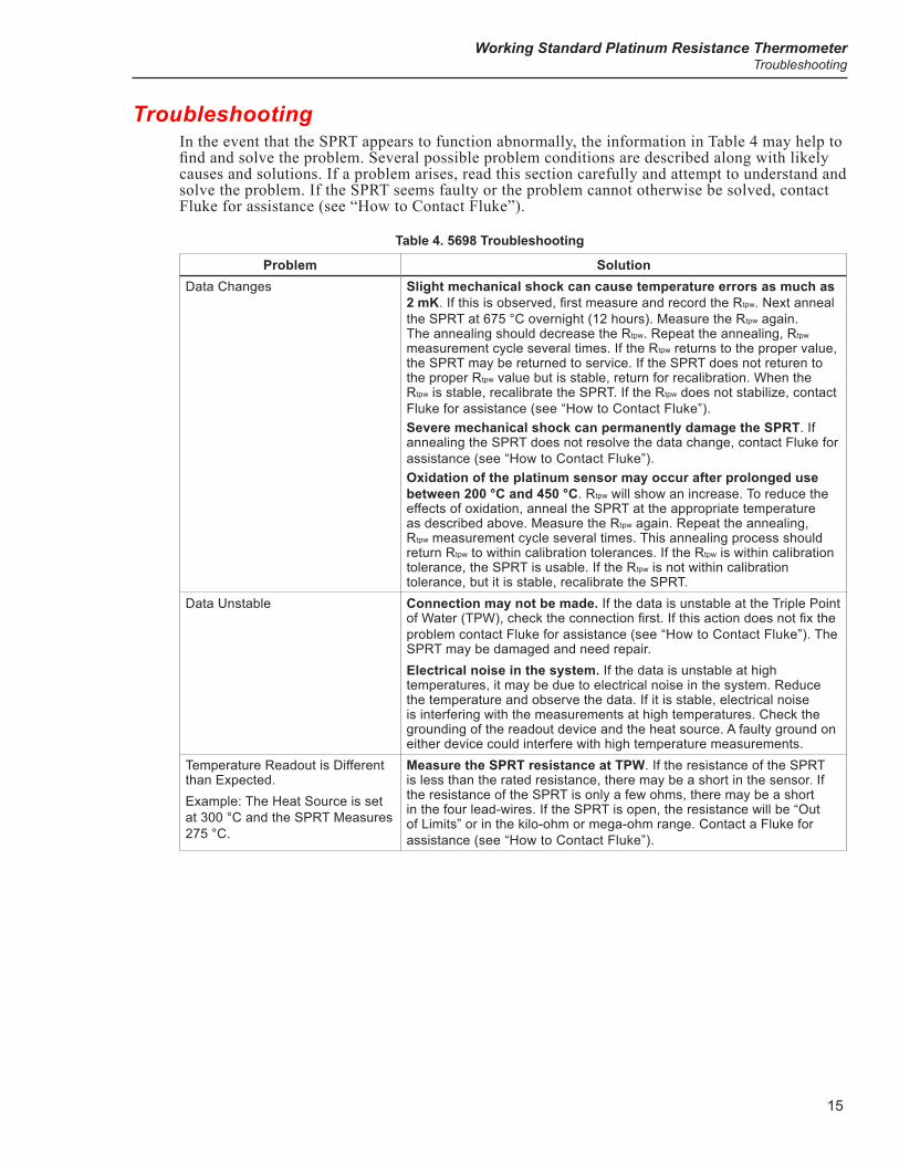
TroubleshootingIn the event that the SPRT appears to function abnormally, the information in Table 4 may help to find and solve the problem. Several possible problem conditions are described along with likely causes and solutions. If a problem arises, read this section carefully and attempt to understand and solve the problem. If the SPRT seems faulty or the problem cannot otherwise be solved, contact Fluke for assistance (see “How to Contact Fluke”).
Table 4. 5698 Troubleshooting
Problem SolutionData Changes Slight mechanical shock can cause temperature errors as much as
2 mK. If this is observed, first measure and record the Rtpw. Next anneal the SPRT at 675 °C overnight (12 hours). Measure the Rtpw again. The annealing should decrease the Rtpw. Repeat the annealing, Rtpw measurement cycle several times. If the Rtpw returns to the proper value, the SPRT may be returned to service. If the SPRT does not returen to the proper Rtpw value but is stable, return for recalibration. When the Rtpw is stable, recalibrate the SPRT. If the Rtpw does not stabilize, contact Fluke for assistance (see “How to Contact Fluke”).Severe mechanical shock can permanently damage the SPRT. If annealing the SPRT does not resolve the data change, contact Fluke for assistance (see “How to Contact Fluke”).Oxidation of the platinum sensor may occur after prolonged use between 200 °C and 450 °C. Rtpw will show an increase. To reduce the effects of oxidation, anneal the SPRT at the appropriate temperature as described above. Measure the Rtpw again. Repeat the annealing, Rtpw measurement cycle several times. This annealing process should return Rtpw to within calibration tolerances. If the Rtpw is within calibration tolerance, the SPRT is usable. If the Rtpw is not within calibration tolerance, but it is stable, recalibrate the SPRT.
Data Unstable Connection may not be made. If the data is unstable at the Triple Point of Water (TPW), check the connection first. If this action does not fix the problem contact Fluke for assistance (see “How to Contact Fluke”). The SPRT may be damaged and need repair.Electrical noise in the system. If the data is unstable at high temperatures, it may be due to electrical noise in the system. Reduce the temperature and observe the data. If it is stable, electrical noise is interfering with the measurements at high temperatures. Check the grounding of the readout device and the heat source. A faulty ground on either device could interfere with high temperature measurements.
Temperature Readout is Different than Expected. Example: The Heat Source is set at 300 °C and the SPRT Measures 275 °C.
Measure the SPRT resistance at TPW. If the resistance of the SPRT is less than the rated resistance, there may be a short in the sensor. If the resistance of the SPRT is only a few ohms, there may be a short in the four lead-wires. If the SPRT is open, the resistance will be “Out of Limits” or in the kilo-ohm or mega-ohm range. Contact a Fluke for assistance (see “How to Contact Fluke”).

5698Users Guide
16