Embed Size (px)
Citation preview

Design, Development, Manufacture, Installation and Servicing for Gas-Leak Alarm
Human Technology & Future
INSTRUCTION MANUAL
MODEL : GTD-2000Ex
FFoorr pprrooppeerr uussee,, pplleeaassee rreeaadd tthhiiss mmaannuuaall ccaarreeffuullllyy!!
Contact Information
http://www.gastech.com.au
24 Baretta RdWangara Western Australia 6065
GasTech Australia Pty Ltd
Fax 1800 999 903 Tel 1800 999 902
GTD-2000Ex
2
For correct operation of a gas detector, checking and calibration must be carried out once three months with a calibration gas. Without periodic checking and calibration, part change time can be missed to lead to disorder of the system. Please contact our technical service or e-mial about a check and a
calibration of the gas detector. For safe use, operation and disassembly of a gas detector are prohibited except by permitted person or a person in charge of Gastron
Thank you very much for purchasing our product.
Our company, Gastron Co., Ltd specializes in gas detectors and gas-monitoring systems, which
earns a reputation for high quality and convenience to use from customers.
We are making constant efforts to satisfy customer’s needs and to develop more satisfactory gas
detectors.
From now on, we will work out a solution to all your concerns about gas detectors. We promise to
give you full satisfaction.
This manual describes how to install, operate, and maintain the GTD-2000Ex series gas detector.
Read carefully this manual and keep it for future reference.
When you have any trouble about this product, contact us:
75-10, Palgog 2-Dong, Sangnok-Gu, Ansan-City, Kyunggi-Do, Korea
Tel: +82-31-4900-800
Fax: +82-31-4900-801
E-mail: [email protected]
Website: www.gastron.com
CAUTION
GTD-2000Ex
4
A TABLE OF CONTENTS
1. INTRODUCTION --------------------------------------------------------------- 5
2. DETECTION PRINCIPLE & STRUCTURE ----------------------- 5
3. S P E C I F I C AT I O N - - - - - - - - - - - - - - - - - - - - - - - - - - - - - - - - - - - - - - 6
4. PART’S NAME AND MAIN FUNCTIONS -------------- 8
5. WIRING DIAGRAMS --------------------------------------------------------- 11
6. APPEARANCE AND DIMENSIONS ----------------------------------- 14
7. PARAMETER PROGRAM ------------------------------------------------- 15
8. CALIBRATION AND MAINTENANCE ------------------------------ 17
9. SENSOR REPLACEMENT & MAINTENANCE ----------------- 22
10. OPTIONAL PARTLIST ---------------------------------------------------- 23
11. BEFORE INSTALLING ------------------------------------------------------ 24
GTD-2000Ex
5
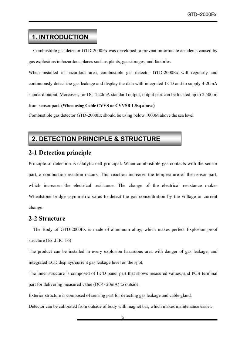
Combustible gas detector GTD-2000Ex was developed to prevent unfortunate accidents caused by
gas explosions in hazardous places such as plants, gas storages, and factories.
When installed in hazardous area, combustible gas detector GTD-2000Ex will regularly and
continuously detect the gas leakage and display the data with integrated LCD and to supply 4-20mA
standard output. Moreover, for DC 4-20mA standard output, output part can be located up to 2,500 m
from sensor part. (When using Cable CVVS or CVVSB 1.5sq above)
Combustible gas detector GTD-2000Ex should be using below 1000M above the sea level.
2-1 Detection principle Principle of detection is catalytic cell principal. When combustible gas contacts with the sensor
part, a combustion reaction occurs. This reaction increases the temperature of the sensor part,
which increases the electrical resistance. The change of the electrical resistance makes
Wheatstone bridge asymmetric so as to detect the gas concentration by the voltage or current
change.
2-2 Structure The Body of GTD-2000Ex is made of aluminum alloy, which makes perfect Explosion proof
structure (Ex d IIC T6)
The product can be installed in every explosion hazardous area with danger of gas leakage, and
integrated LCD displays current gas leakage level on the spot.
The inner structure is composed of LCD panel part that shows measured values, and PCB terminal
part for delivering measured value (DC4~20mA) to outside.
Exterior structure is composed of sensing part for detecting gas leakage and cable gland.
Detector can be calibrated from outside of body with magnet bar, which makes maintenance easier.
1. INTRODUCTION
2. DETECTION PRINCIPLE & STRUCTURE
GTD-2000Ex
6
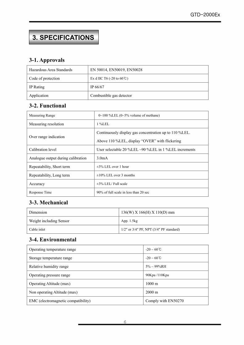
3-1. Approvals Hazardous Area Standards EN 50014, EN50019, EN50028
Code of protection Ex d IIC T6 (-20 to 60)
IP Rating IP 66/67
Application Combustible gas detector
3-2. Functional Measuring Range 0~100 %LEL (0~5% volume of methane)
Measuring resolution 1 %LEL
Over range indication Continuously display gas concentration up to 110 %LEL.
Above 110 %LEL, display “OVER” with flickering
Calibration level User selectable 20 %LEL ~90 %LEL in 1 %LEL increments
Analogue output during calibration 3.0mA
Repeatability, Short term ±3% LEL over 1 hour
Repeatability, Long term ±10% LEL over 3 months
Accuracy ±3% LEL/ Full scale
Response Time 90% of full scale in less than 20 sec
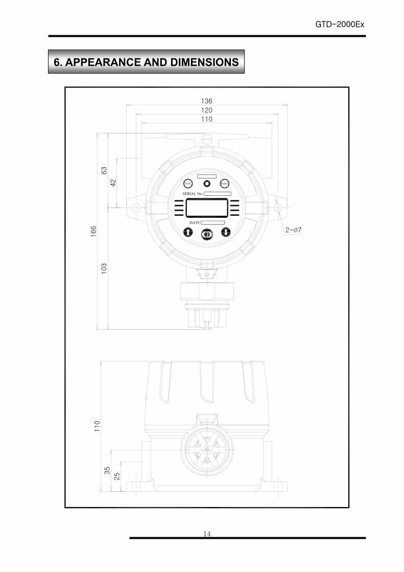
3-3. Mechanical Dimension 136(W) X 166(H) X 110(D) mm
Weight including Sensor App. 1.5kg
Cable inlet 1/2" or 3/4" PF, NPT (3/4" PF standard)
3-4. Environmental Operating temperature range -20 ~ 60
Storage temperature range -20 ~ 60
Relative humidity range 5% ~ 99%RH
Operating pressure range 90Kpa /110Kpa
Operating Altitude (max) 1000 m
Non operating Altitude (max) 2000 m
EMC (electromagnetic compatibility) Comply with EN50270
3. SPECIFICATIONS
GTD-2000Ex
7
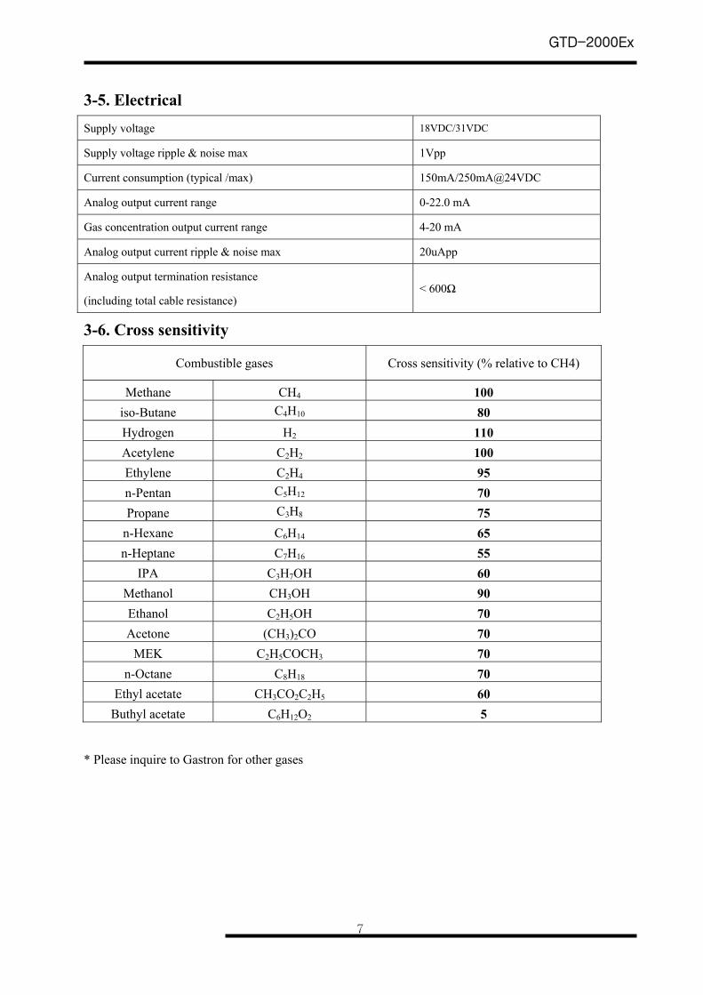
3-5. Electrical Supply voltage 18VDC/31VDC
Supply voltage ripple & noise max 1Vpp
Current consumption (typical /max) 150mA/250mA@24VDC
Analog output current range 0-22.0 mA
Gas concentration output current range 4-20 mA
Analog output current ripple & noise max 20uApp
Analog output termination resistance
(including total cable resistance) < 600Ω
3-6. Cross sensitivity
Combustible gases Cross sensitivity (% relative to CH4)
Methane CH4 100 iso-Butane C4H10 80 Hydrogen H2 110 Acetylene C2H2 100 Ethylene C2H4 95 n-Pentan C5H12 70 Propane C3H8 75
n-Hexane C6H14 65 n-Heptane C7H16 55
IPA C3H7OH 60 Methanol CH3OH 90 Ethanol C2H5OH 70 Acetone (CH3)2CO 70
MEK C2H5COCH3 70 n-Octane C8H18 70
Ethyl acetate CH3CO2C2H5 60 Buthyl acetate C6H12O2 5
* Please inquire to Gastron for other gases
GTD-2000Ex
8
G:LEDOM xE0002-DT
RO
TC
ET
ED
S RO
KNI
ED
AAE
M
AG
CO . , LTD .GAS TRON
U PTFIL
P R E S S
LU P
TFIP R E S S5
15
13
RESET
1 23 4
6
78 9
10 11
14
13
15
1216
SERIAL No.
DATE
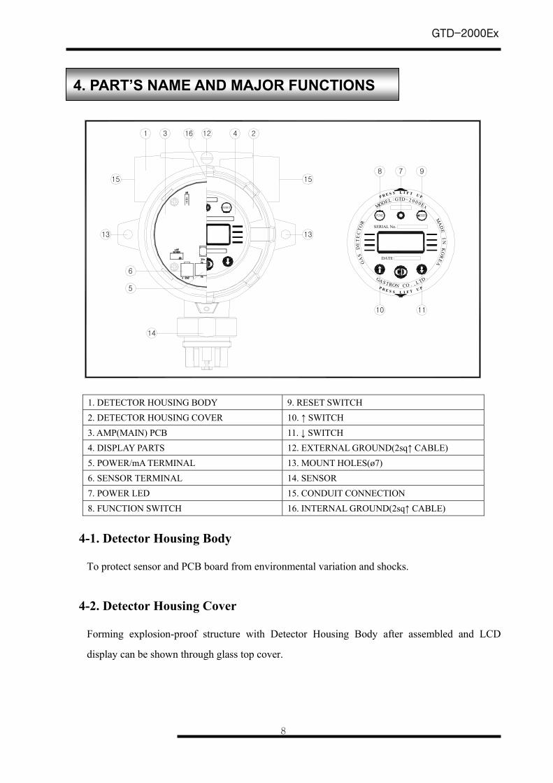
1. DETECTOR HOUSING BODY 9. RESET SWITCH 2. DETECTOR HOUSING COVER 10. ↑ SWITCH 3. AMP(MAIN) PCB 11. ↓ SWITCH 4. DISPLAY PARTS 12. EXTERNAL GROUND(2sq↑ CABLE) 5. POWER/mA TERMINAL 13. MOUNT HOLES(ø7) 6. SENSOR TERMINAL 14. SENSOR 7. POWER LED 15. CONDUIT CONNECTION 8. FUNCTION SWITCH 16. INTERNAL GROUND(2sq↑ CABLE)
4-1. Detector Housing Body
To protect sensor and PCB board from environmental variation and shocks.
4-2. Detector Housing Cover
Forming explosion-proof structure with Detector Housing Body after assembled and LCD
display can be shown through glass top cover.
4. PART’S NAME AND MAJOR FUNCTIONS
GTD-2000Ex
9
4-3. AMP PCB
Amplifies the tiny signal of sensor to transmit DC 4-20mA signal, It also sends signal data to
LCD display.
4-4. Display Parts
Converts analogue signal from AMP/Terminal (Transmitter) PCB to digital signal and feed the
converted signal to LCD. It also lights power lamp to indicate current power status.
4-5. Power/mA Terminal
CN1 is composed of connection terminal for DC 21-27V power (+, -, ET) and for 4-20mA
signal. (mA, -) .
4-6. Sensor Terminal
CN2 is connection terminal for sensor. (Red, White, Green and Blue)
4-7. Power LED
When the power is supplied, the lamp will turns on.
4-8. Function switch
- When setting parameter, the detector goes into program mode by touching this switch with
magnet bar for over 2 seconds. (Program mode, Calibration mode, Maintenance mode, Test
mode)
- Also, This switch is used for data input.
4-9. Reset switch
In order to go back to previous mode or cancel current action during setting parameters, touch this
switch with magnet bar once. (Every touch will make the detector go back to previous mode)
GTD-2000Ex
10
4-10. (↑) switch
When changing the mode or number, touch this switch with magnet bar once and the detector
will go to next stage or the number will be increased.
4-11. (↓) switch
When changing the mode or number, touch the switch with magnet bar once and the mode will
go to previous stage or the number will be decreased.
4-12. External Ground
This grounding terminal protects detector from external noises or high electric field
4-13. Mount Hole (Ф7×3ea)
These holes are used to fix the detector to wall and other places.
4-14. Sensor
Sensor detects actual gas leakage and sends electric signal to AMP PCB.
4-15. Cable inlet
There are two types of cable inlets, PF3/4" and PF or NPT 1/2". (Standard item is PF3/4”)
4-16. Internal Ground
Grounding terminal of the inside which protects the detector from external noises or high electric
field
GTD-2000Ex
11
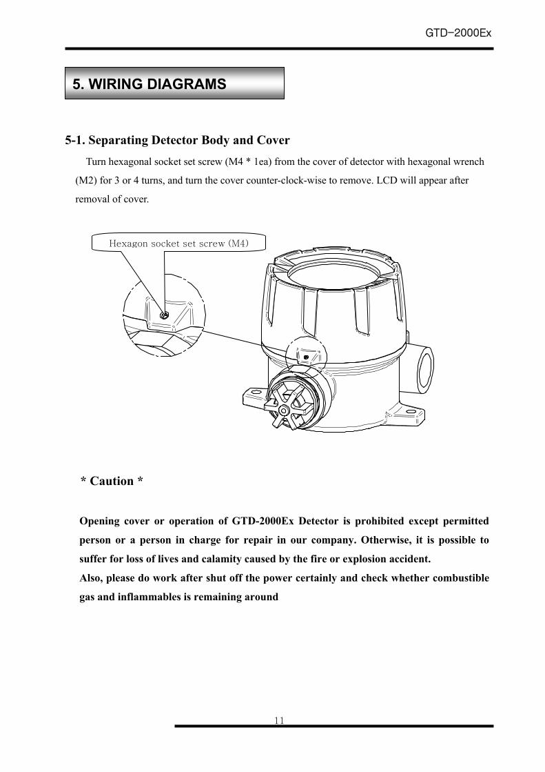
5-1. Separating Detector Body and Cover
Turn hexagonal socket set screw (M4 * 1ea) from the cover of detector with hexagonal wrench
(M2) for 3 or 4 turns, and turn the cover counter-clock-wise to remove. LCD will appear after
removal of cover.
* Caution *
Opening cover or operation of GTD-2000Ex Detector is prohibited except permitted
person or a person in charge for repair in our company. Otherwise, it is possible to
suffer for loss of lives and calamity caused by the fire or explosion accident.
Also, please do work after shut off the power certainly and check whether combustible
gas and inflammables is remaining around
5. WIRING DIAGRAMS
Hexagon socket set screw (M4)
GTD-2000Ex
12
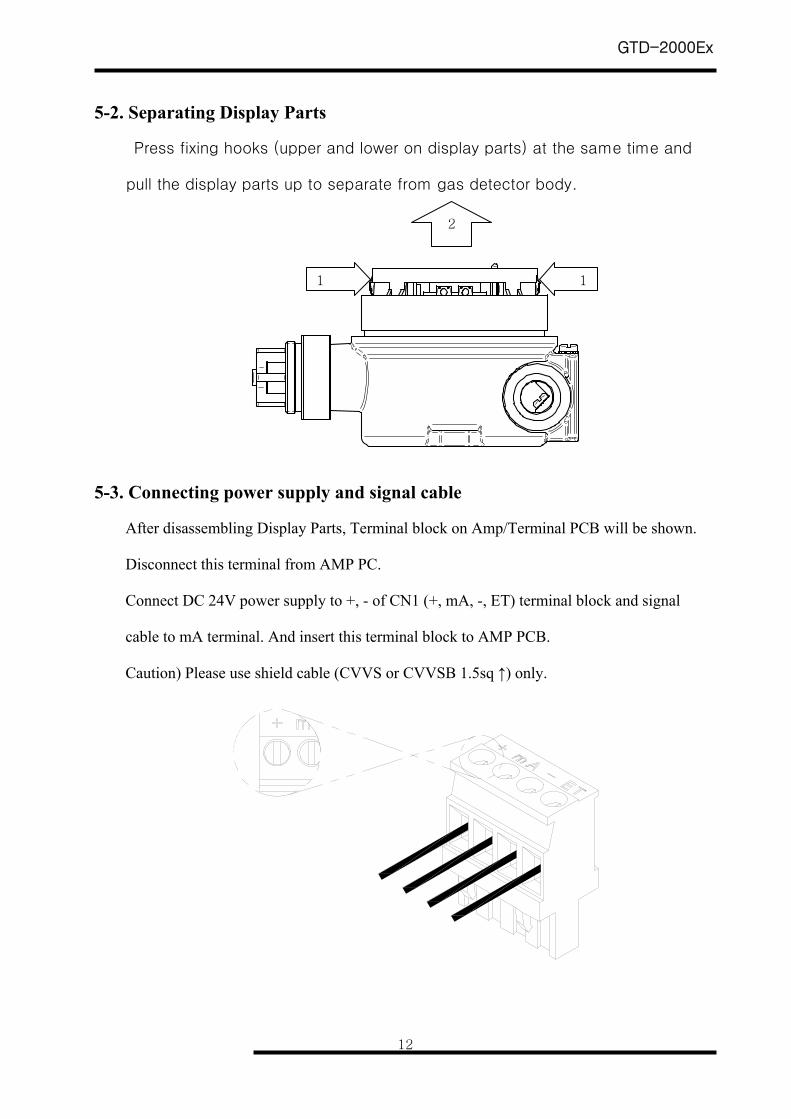
5-2. Separating Display Parts
Press fixing hooks (upper and lower on display parts) at the same time and
pull the display parts up to separate from gas detector body.
5-3. Connecting power supply and signal cable
After disassembling Display Parts, Terminal block on Amp/Terminal PCB will be shown.
Disconnect this terminal from AMP PC.
Connect DC 24V power supply to +, - of CN1 (+, mA, -, ET) terminal block and signal
cable to mA terminal. And insert this terminal block to AMP PCB.
Caution) Please use shield cable (CVVS or CVVSB 1.5sq ↑) only.
1 1
2
GTD-2000Ex
13
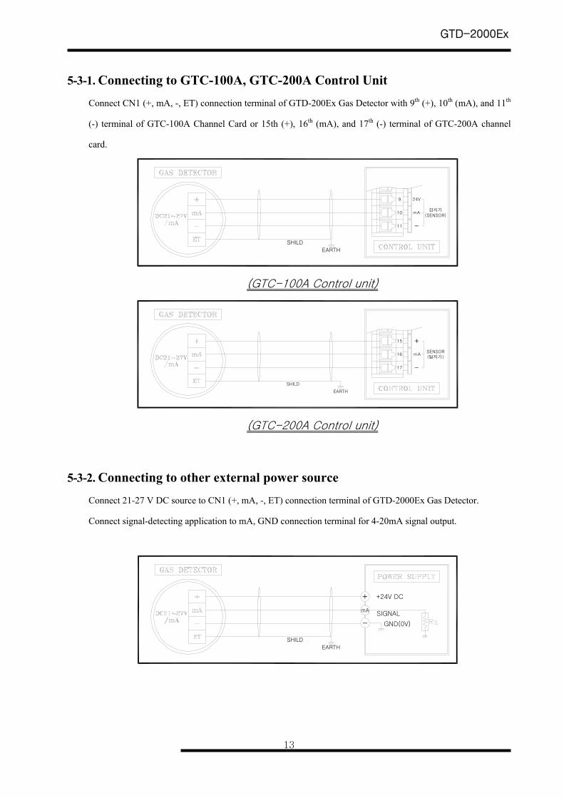
5-3-1. Connecting to GTC-100A, GTC-200A Control Unit Connect CN1 (+, mA, -, ET) connection terminal of GTD-200Ex Gas Detector with 9th (+), 10th (mA), and 11th
(-) terminal of GTC-100A Channel Card or 15th (+), 16th (mA), and 17th (-) terminal of GTC-200A channel
card.
11
10
9
mA
24V
SHILD
EARTH
감지기(SENSOR)
-
(GTC-100A Control unit)
-
mA
SHILD
EARTH
SENSOR(탐지기)
17
16
15 +
(GTC-200A Control unit)
5-3-2. Connecting to other external power source Connect 21-27 V DC source to CN1 (+, mA, -, ET) connection terminal of GTD-2000Ex Gas Detector.
Connect signal-detecting application to mA, GND connection terminal for 4-20mA signal output.
+
GND(0V)
mA
-
+24V DC
SIGNAL
SHILD
EARTH
GTD-2000Ex
14
103
253
5
110
110
120
136
42
63
166 2-Ø7
RESET
SERIAL No.
DATE
FUNC
6. APPEARANCE AND DIMENSIONS
GTD-2000Ex
15
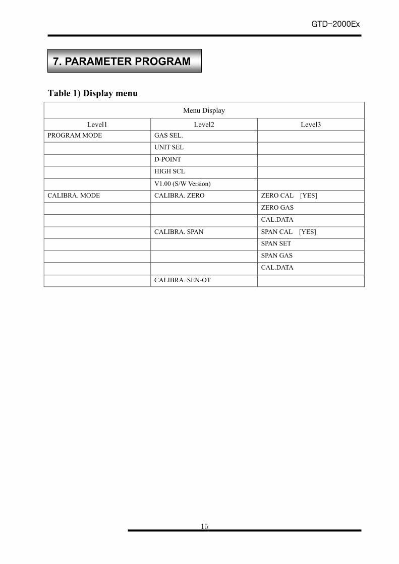
Table 1) Display menu
Menu Display
Level1 Level2 Level3 PROGRAM MODE GAS SEL.
UNIT SEL
D-POINT
HIGH SCL
V1.00 (S/W Version)
CALIBRA. MODE CALIBRA. ZERO ZERO CAL [YES]
ZERO GAS
CAL.DATA
CALIBRA. SPAN SPAN CAL [YES]
SPAN SET
SPAN GAS
CAL.DATA
CALIBRA. SEN-OT
7. PARAMETER PROGRAM
GTD-2000Ex
16
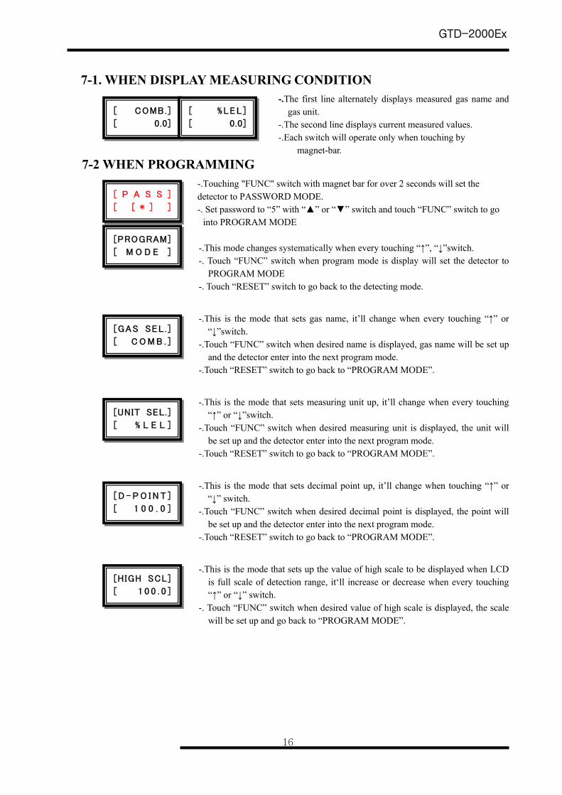
7-1. WHEN DISPLAY MEASURING CONDITION -.The first line alternately displays measured gas name and
gas unit. -.The second line displays current measured values. -.Each switch will operate only when touching by
magnet-bar. 7-2 WHEN PROGRAMMING
-.Touching "FUNC" switch with magnet bar for over 2 seconds will set the detector to PASSWORD MODE. -. Set password to “5” with “” or “” switch and touch “FUNC” switch to go
into PROGRAM MODE -.This mode changes systematically when every touching “↑”, “↓”switch. -. Touch “FUNC” switch when program mode is display will set the detector to
PROGRAM MODE -. Touch “RESET” switch to go back to the detecting mode.
-.This is the mode that sets gas name, it’ll change when every touching “↑” or “↓”switch.
-.Touch “FUNC” switch when desired name is displayed, gas name will be set up and the detector enter into the next program mode.
-.Touch “RESET” switch to go back to “PROGRAM MODE”.
-.This is the mode that sets measuring unit up, it’ll change when every touching “↑” or “↓”switch.
-.Touch “FUNC” switch when desired measuring unit is displayed, the unit will be set up and the detector enter into the next program mode.
-.Touch “RESET” switch to go back to “PROGRAM MODE”.
-.This is the mode that sets decimal point up, it’ll change when touching “↑” or “↓” switch.
-.Touch “FUNC” switch when desired decimal point is displayed, the point will be set up and the detector enter into the next program mode.
-.Touch “RESET” switch to go back to “PROGRAM MODE”.
-.This is the mode that sets up the value of high scale to be displayed when LCD is full scale of detection range, it‘ll increase or decrease when every touching “↑” or “↓” switch.
-. Touch “FUNC” switch when desired value of high scale is displayed, the scale will be set up and go back to “PROGRAM MODE”.
[ COMB.]
[ 0.0]
[ %LEL ]
[ 0.0]
[PROGRAM]
[ M O D E ]
[GAS SEL . ]
[ C O M B . ]
[HIGH SCL]
[ 1 0 0 . 0 ]
[UNIT SEL.]
[ % L E L ]
[ D - P O I N T ]
[ 1 0 0 . 0 ]
[ P A S S ]
[ [ * ] ]
GTD-2000Ex
17
8-1. Supplying Electrical Power After connecting DC 21-27V power source to CN1 terminal (+), (-) on Amp PCB, power LED will light and
LCD will operate as showing "SELF TEST".
Stabilization time of 30 minutes ※ is needed after turning on the device. After stabilization time, the detector
will operate normally.
8-2. Confirming Output of Detector Connect multimeter (DC ampere meter) to CN1 4-20mA signal terminal (mA), (V-). After stabilization time,
check LCD display and signal output. At this time, the multimeter should show 4mA when LCD is zero, and
the multimeter should read 20mA when LCD is full scale of set range.
8-3. Calibration Combustible gas detector requires 30minutes of stabilization time after power on due to properties of the sensor.
However, standards for management may vary due to field condition.
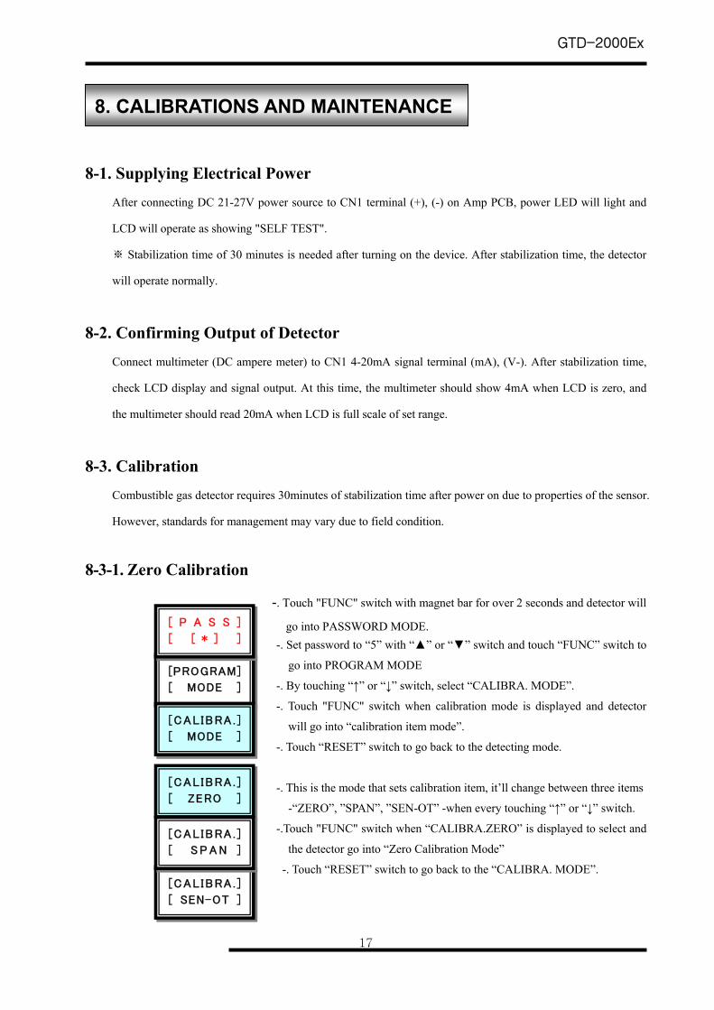
8-3-1. Zero Calibration
-. Touch "FUNC" switch with magnet bar for over 2 seconds and detector will
go into PASSWORD MODE. -. Set password to “5” with “” or “” switch and touch “FUNC” switch to
go into PROGRAM MODE
-. By touching “↑” or “↓” switch, select “CALIBRA. MODE”.
-. Touch "FUNC" switch when calibration mode is displayed and detector
will go into “calibration item mode”.
-. Touch “RESET” switch to go back to the detecting mode.
-. This is the mode that sets calibration item, it’ll change between three items
-“ZERO”, ”SPAN”, ”SEN-OT” -when every touching “↑” or “↓” switch.
-.Touch "FUNC" switch when “CALIBRA.ZERO” is displayed to select and
the detector go into “Zero Calibration Mode”
-. Touch “RESET” switch to go back to the “CALIBRA. MODE”.
8. CALIBRATIONS AND MAINTENANCE
[PROGRAM]
[ MODE ]
[CAL IBRA . ]
[ MODE ]
[CAL IBRA . ]
[ ZERO ]
[CAL IBRA . ]
[ SEN-OT ]
[CAL IBRA . ]
[ S P A N ]
[ P A S S ]
[ [ * ] ]
GTD-2000Ex
18
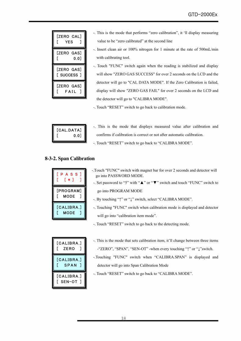
-. This is the mode that performs “zero calibration”, it ‘ll display measuring
value to be “zero calibrated” at the second line
-. Insert clean air or 100% nitrogen for 1 minute at the rate of 500mL/min
with calibrating tool.
-. Touch "FUNC" switch again when the reading is stabilized and display
will show "ZERO GAS SUCCESS" for over 2 seconds on the LCD and the
detector will go to "CAL DATA MODE". If the Zero Calibration is failed,
display will show "ZERO GAS FAIL" for over 2 seconds on the LCD and
the detector will go to "CALIBRA MODE".
-. Touch “RESET” switch to go back to calibration mode.
-. This is the mode that displays measured value after calibration and
confirms if calibration is correct or not after automatic calibration.
-. Touch “RESET” switch to go back to “CALIBRA MODE”.
8-3-2. Span Calibration
-.Touch "FUNC" switch with magnet bar for over 2 seconds and detector will go into PASSWORD MODE.
-. Set password to “5” with “” or “” switch and touch “FUNC” switch to
go into PROGRAM MODE
-. By touching “↑” or “↓” switch, select “CALIBRA MODE”.
-. Touching "FUNC" switch when calibration mode is displayed and detector
will go into “calibration item mode”.
-. Touch “RESET” switch to go back to the detecting mode.
-. This is the mode that sets calibration item, it’ll change between three items
-“ZERO”, “SPAN”, “SEN-OT” -when every touching “↑” or “↓”switch.
-.Touching "FUNC" switch when “CALIBRA.SPAN” is displayed and
detector will go into Span Calibration Mode
-. Touch “RESET” switch to go back to “CALIBRA MODE”.
[ZERO GAS]
[ 0 .0 ]
[ZERO GAS]
[ SUCCESS ]
[ZERO GAS]
[ F A I L ]
[PROGRAM]
[ MODE ]
[CAL IBRA . ]
[ MODE ]
[CAL IBRA . ]
[ ZERO ]
[CAL.DATA]
[ 0 .0 ]
[CAL IBRA . ]
[ SEN-OT ]
[CAL IBRA . ]
[ S P A N ]
[ZERO CAL]
[ YES ]
[ P A S S ]
[ [ * ] ]
GTD-2000Ex
19
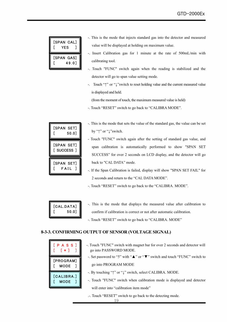
-. This is the mode that injects standard gas into the detector and measured
value will be displayed at holding on maximum value.
-. Insert Calibration gas for 1 minute at the rate of 500mL/min with
calibrating tool.
-. Touch "FUNC" switch again when the reading is stabilized and the
detector will go to span value setting mode.
-. Touch “↑” or “↓”switch to reset holding value and the current measured value
is displayed and held.
(from the moment of touch, the maximum measured value is held)
-. Touch “RESET” switch to go back to “CALIBRA MODE”.
-. This is the mode that sets the value of the standard gas, the value can be set
by “↑” or “↓”switch.
- Touch "FUNC" switch again after the setting of standard gas value, and
span calibration is automatically performed to show "SPAN SET
SUCCESS” for over 2 seconds on LCD display, and the detector will go
back to "CAL DATA” mode.
-. If the Span Calibration is failed, display will show "SPAN SET FAIL" for
2 seconds and return to the “CAL DATA MODE”.
-. Touch “RESET” switch to go back to the “CALIBRA. MODE”.
-. This is the mode that displays the measured value after calibration to
confirm if calibration is correct or not after automatic calibration.
-. Touch “RESET” switch to go back to “CALIBRA. MODE”
8-3-3. CONFIRMING OUTPUT OF SENSOR (VOLTAGE SIGNAL)
-. Touch "FUNC" switch with magnet bar for over 2 seconds and detector will go into PASSWORD MODE.
-. Set password to “5” with “” or “” switch and touch “FUNC” switch to
go into PROGRAM MODE
-. By touching “↑” or “↓” switch, select CALIBRA. MODE.
-. Touch "FUNC" switch when calibration mode is displayed and detector
will enter into “calibration item mode”
.-. Touch “RESET” switch to go back to the detecting mode.
[SPAN SET]
[ 50 .0 ]
[SPAN SET]
[ SUCCESS ]
[SPAN SET]
[ F A I L ]
[SPAN GAS]
[ 4 9 . 0 ]
[PROGRAM]
[ MODE ]
[CAL IBRA . ]
[ MODE ]
[CAL.DATA]
[ 50 .0 ]
[SPAN CAL]
[ YES ]
[ P A S S ]
[ [ * ] ]
GTD-2000Ex
20
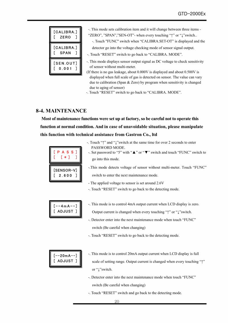
-. This mode sets calibration item and it will change between three items - “ZERO”, ”SPAN”,”SEN-OT”- when every touching “↑” or “↓”switch..
-. Touch "FUNC" switch when “CALIBRA.SET-OT” is displayed and the
detector go into the voltage checking mode of sensor signal output.
-. Touch “RESET” switch to go back to “CALIBRA. MODE”.
-. This mode displays sensor output signal as DC voltage to check sensitivity of sensor without multi-meter.
(If there is no gas leakage, about 0.000V is displayed and about 0.500V is displayed when full scale of gas is detected on sensor. The value can vary due to calibration (Span & Zero) by program when sensitivity is changed due to aging of sensor)
-. Touch “RESET” switch to go back to “CALIBRA. MODE”.
8-4. MAINTENANCE
Most of maintenance functions were set up at factory, so be careful not to operate this
function at normal condition. And in case of unavoidable situation, please manipulate
this function with technical assistance from Gastron Co., ltd
-. Touch “↑” and “↓”switch at the same time for over 2 seconds to enter PASSWORD MODE.
-. Set password to “5” with “” or “” switch and touch “FUNC” switch to
go into this mode.
-.This mode detects voltage of sensor without multi-meter. Touch “FUNC”
switch to enter the next maintenance mode.
- The applied voltage to sensor is set around 2.6V -. Touch “RESET” switch to go back to the detecting mode.
-. This mode is to control 4mA output current when LCD display is zero.
Output current is changed when every touching “↑” or “↓”switch.
-. Detector enter into the next maintenance mode when touch “FUNC”
switch (Be careful when changing)
-. Touch “RESET” switch to go back to the detecting mode.
-. This mode is to control 20mA output current when LCD display is full
scale of setting range. Output current is changed when every touching “↑”
or “↓”switch.
-. Detector enter into the next maintenance mode when touch “FUNC”
switch (Be careful when changing)
-. Touch “RESET” switch and go back to the detecting mode.
[CAL IBRA . ]
[ ZERO ]
[CAL IBRA . ]
[ SPAN ]
[ S E N . O U T ]
[ 0 . 0 0 1 ]
[ - - 4 m A - - ]
[ ADJUST ]
[--20mA--]
[ ADJUST ]
[SENSOR-V]
[ 2 . 6 0 0 ]
[ P A S S ]
[ [ * ] ]
GTD-2000Ex
21
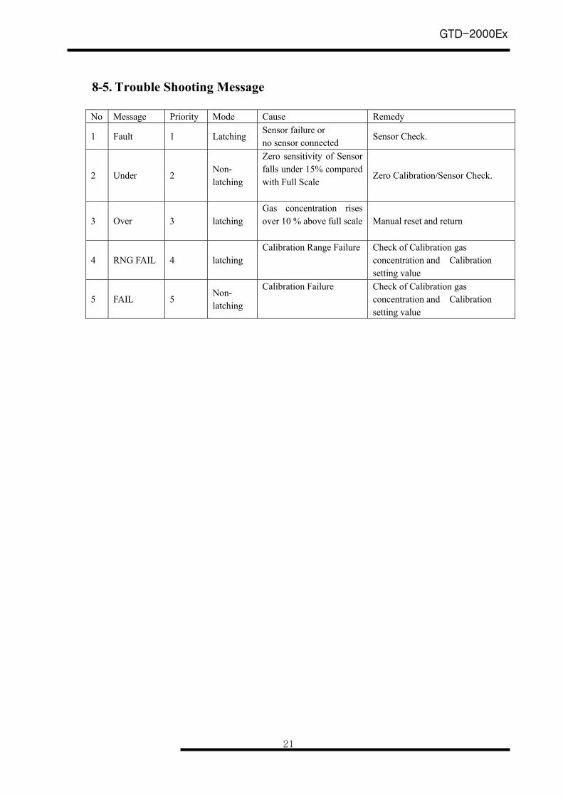
8-5. Trouble Shooting Message No Message Priority Mode Cause Remedy
1 Fault 1 Latching Sensor failure or no sensor connected
Sensor Check.
2 Under 2 Non- latching
Zero sensitivity of Sensor falls under 15% compared with Full Scale
Zero Calibration/Sensor Check.
3 Over 3 latching Gas concentration rises over 10 % above full scale
Manual reset and return
4 RNG FAIL 4 latching Calibration Range Failure Check of Calibration gas
concentration and Calibration setting value
5 FAIL 5 Non- latching
Calibration Failure Check of Calibration gas concentration and Calibration setting value
GTD-2000Ex
22
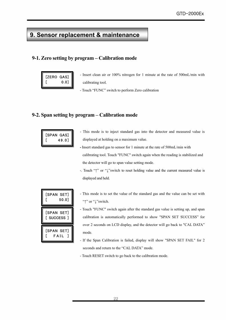
9-1. Zero setting by program – Calibration mode
- Insert clean air or 100% nitrogen for 1 minute at the rate of 500mL/min with
calibrating tool.
- Touch “FUNC” switch to perform Zero calibration
9-2. Span setting by program – Calibration mode
- This mode is to inject standard gas into the detector and measured value is
displayed at holding on a maximum value. - Insert standard gas to sensor for 1 minute at the rate of 500mL/min with
calibrating tool. Touch "FUNC" switch again when the reading is stabilized and
the detector will go to span value setting mode.
-. Touch “↑” or “↓”switch to reset holding value and the current measured value is
displayed and held.
- This mode is to set the value of the standard gas and the value can be set with
“↑” or “↓”switch.
- Touch "FUNC" switch again after the standard gas value is setting up, and span
calibration is automatically performed to show "SPAN SET SUCCESS” for
over 2 seconds on LCD display, and the detector will go back to "CAL DATA”
mode.
- If the Span Calibration is failed, display will show "SPAN SET FAIL" for 2
seconds and return to the “CAL DATA” mode.
- Touch RESET switch to go back to the calibration mode.
9. Sensor replacement & maintenance
[ZERO GAS]
[ 0 .0 ]
[SPAN SET]
[ 50 .0 ]
[SPAN SET]
[ SUCCESS ]
[SPAN GAS]
[ 4 9 . 0 ]
[SPAN SET]
[ F A I L ]
GTD-2000Ex
23
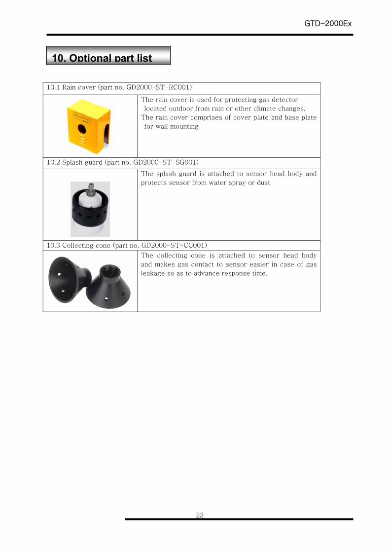
10.1 Rain cover (part no. GD2000-ST-RC001)
The rain cover is used for protecting gas detector
located outdoor from rain or other climate changes.
The rain cover comprises of cover plate and base plate
for wall mounting
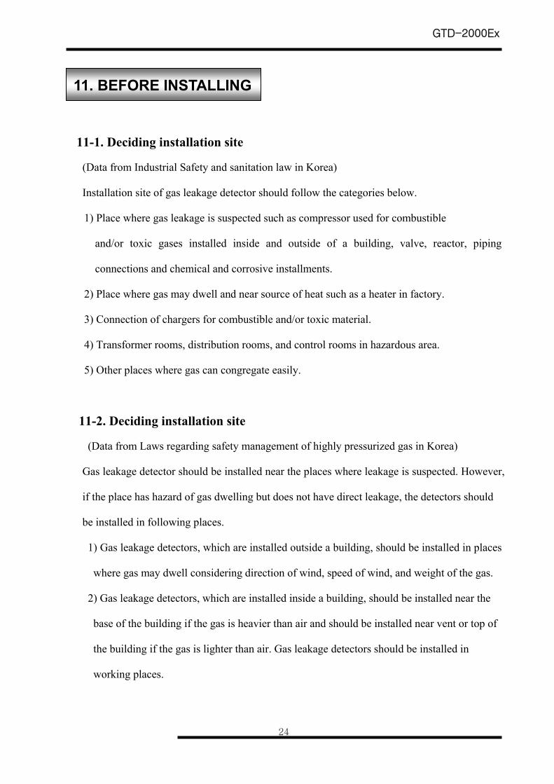
10.2 Splash guard (part no. GD2000-ST-SG001)
The splash guard is attached to sensor head body and
protects sensor from water spray or dust
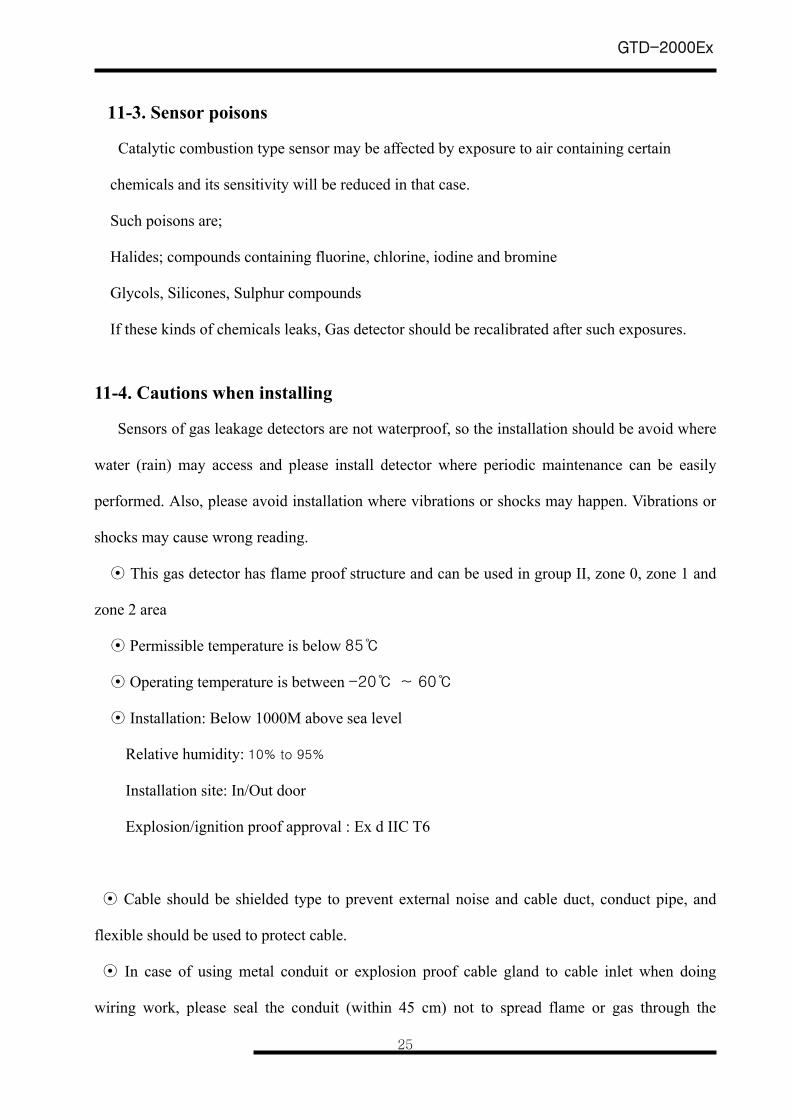
10.3 Collecting cone (part no. GD2000-ST-CC001)
The collecting cone is attached to sensor head body
and makes gas contact to sensor easier in case of gas
leakage so as to advance response time.
10. Optional part list
GTD-2000Ex
24
11-1. Deciding installation site
(Data from Industrial Safety and sanitation law in Korea)
Installation site of gas leakage detector should follow the categories below.
1) Place where gas leakage is suspected such as compressor used for combustible
and/or toxic gases installed inside and outside of a building, valve, reactor, piping
connections and chemical and corrosive installments.
2) Place where gas may dwell and near source of heat such as a heater in factory.
3) Connection of chargers for combustible and/or toxic material.
4) Transformer rooms, distribution rooms, and control rooms in hazardous area.
5) Other places where gas can congregate easily.
11-2. Deciding installation site
(Data from Laws regarding safety management of highly pressurized gas in Korea)
Gas leakage detector should be installed near the places where leakage is suspected. However,
if the place has hazard of gas dwelling but does not have direct leakage, the detectors should
be installed in following places.
1) Gas leakage detectors, which are installed outside a building, should be installed in places
where gas may dwell considering direction of wind, speed of wind, and weight of the gas.
2) Gas leakage detectors, which are installed inside a building, should be installed near the
base of the building if the gas is heavier than air and should be installed near vent or top of
the building if the gas is lighter than air. Gas leakage detectors should be installed in
working places.
11. BEFORE INSTALLING
GTD-2000Ex
25
11-3. Sensor poisons
Catalytic combustion type sensor may be affected by exposure to air containing certain
chemicals and its sensitivity will be reduced in that case.
Such poisons are;
Halides; compounds containing fluorine, chlorine, iodine and bromine
Glycols, Silicones, Sulphur compounds
If these kinds of chemicals leaks, Gas detector should be recalibrated after such exposures.
11-4. Cautions when installing
Sensors of gas leakage detectors are not waterproof, so the installation should be avoid where
water (rain) may access and please install detector where periodic maintenance can be easily
performed. Also, please avoid installation where vibrations or shocks may happen. Vibrations or
shocks may cause wrong reading.
⊙ This gas detector has flame proof structure and can be used in group II, zone 0, zone 1 and
zone 2 area
⊙ Permissible temperature is below 85
⊙ Operating temperature is between -20 ~ 60
⊙ Installation: Below 1000M above sea level
Relative humidity: 10% to 95%
Installation site: In/Out door
Explosion/ignition proof approval : Ex d IIC T6
⊙ Cable should be shielded type to prevent external noise and cable duct, conduct pipe, and
flexible should be used to protect cable.
⊙ In case of using metal conduit or explosion proof cable gland to cable inlet when doing
wiring work, please seal the conduit (within 45 cm) not to spread flame or gas through the
GTD-2000Ex
26
conduit.
⊙ When connecting this detector with conduit, the screw thread should be more than 5 times.
(Every material for cable inlet "CABLE GLAND and SEALING FITTING..etc” should be
passed for an authorization certainly!)