Embed Size (px)
Citation preview

INSTRUCTION MANUAL
IPM 3600
3 Phase Power Analyser
FREN IT DE ES

CONTENTS / EN
04/30/13 Version No. 01
CONTENTSTitle Page
I. SAFETY INFORMATION ...........................................................................1
II. INTRODUCTION........................................................................................3
III. SPECIFICATIONS .....................................................................................4
3-1 Environmental Conditions ..........................................................................43-2 Safety Specifications ..................................................................................43-3 General Specifications................................................................................53-4 Electrical Specification................................................................................5
IV. PARTS & CONTROLS ..............................................................................9
4-1 Description of Parts & Control keys............................................................94-2 Description of Display............................................................................... 11
V. OPERATING INSTRUCTIONS ................................................................14
5-1 ICA3600 AC Current Probe Connection...................................................145-2 Single-Phase 2-Wire (1P2W) Power System Measurement....................165-3 Single-Phase 3-Wire (1P3W) Power System Measurement....................185-4 Three-Phase 3-Wire (3P3W) Power System Measurement ....................205-5 Three-Phase 4-Wire (3P4W) Power System Measurement ....................225-6 Single Phase Current Measurement .....................................................255-7 Manual Data Memory and Read Function Operation...............................255-8 Auto Data logging Function Operation .....................................................265-9 Phase Sequence Measurement ...............................................................275-10 Voltage, Current Waveform and Harmonic Analyzer..............................285-11 Disable Auto Power Off Function............................................................28
VI. MAINTENANCE.......................................................................................29
6-1 General Maintenance ...............................................................................296-2 Battery Replacement................................................................................29
VII. SOFTWARE INSTALLATION AND OPERATION ...................................30

SAFETY INFORMATION / EN
EN-1 04/30/13 Version No. 01
I. SAFETY INFORMATION
The following symbols may appear on the instrument and in this instruction manual:
Caution refer to this manual before using the instrument.This mark indicates explanation, which is particularly important that the user shouldread before using the instrument.
Risk of electric shock
Instrument is protected by double insulation or reinforced insulation.
Conforms to relevant EU directives
Dispose of in accordance with local regulations.
Safety InformationRead and understand this instruction manual completely before using this instrument. Failure toobserve the warnings and cautions in this instruction manual may result in injury, death or damageto the instrument and other equipment or property.
If this instrument is used in a manner not specified in these instructions, the protection provided bythe instrument may be impaired
DANGER• Do not store or use the instrument where it will be exposed to direct sunlight, high temperature,
high humidity, or condensation• The instrument is designed for indoor use and can be safely used at temperatures ranging from
0°C to 40°C• To prevent electric shock, do not allow the instrument to come into contact with water, do not
use in damp conditions and do not use the unit with wet hands• Do not use the instrument in hazardous areas or around explosive or corrosive gases or vapours• Examine the instrument and probes before use, do not use them if they are damaged• Do not apply more than the rated voltage, as marked on the instrument and probes, between
terminals or between any terminal and earth ground• To prevent electric shock, de-energise power systems before making connections whenever
possible• Whenever possible, make connections to the output side of a circuit breaker to provide better
short circuit protection.• Use caution with voltages above 30 Vac rms, 42 Vac peak, or 60 Vdc. These voltages pose a
shock hazard• Use extreme caution when working around bare conductors or bus bars. Accidental contact with
the conductor could result in electric shock.• Wear suitable personal protective equipment when working around or near hazardous live
conductors which could be accessible

SAFETY INFORMATION / EN
04/30/13 Version No. 01 EN-2
WARNING
• Do not hold the test leads or probes beyond the finger guards or tactile barriers
• Remove all probes, test leads and accessories that are not required for the test
• Always use proper terminals, switch position, and range for measurements
• Verify the instrument is operating correctly by measuring a known voltage before use. If in doubt,have the instrument serviced
• To avoid false readings that can lead to electric shock and injury, replace battery as soon as the
low battery indicator “ BT
” appears
• Follow all legal requirements
• Obey posted instructions
• Never assume that a circuit is de-energized, check it first
• Always set up the measurement first, then connect the test leads and probes to theinstrument before connecting to the circuit under test
• Connect the ground lead first, then the voltage leads and the current probe, Disconnect in thereverse order
• Route all test leads carefully
• Remove test leads from instrument before opening the battery door or instrument case
CAUTION: The measurement inputs U1, U2 and U3 are not isolated from each other, input Nis the common reference point. Connecting either U1, U2 or U3 to the circuitmeans that the others are also live and therefore a danger of electric shock ispresent. To avoid electrical shock, connect only the probes and test leadsrequired for the test.

INTRODUCTION / EN
EN-3 04/30/13 Version No. 01
II. INTRODUCTIONThe IPM 3600 is a 3 phase power analyser for portable measurement within public mainssupplies.
The analyzer can be used to analyse and trouble shoot power quality issues, improve powerefficiency, manage energy costs, analyze harmonics, optimize power system performance,improve power quality and analyze system data to design optimal upgrades.
Features• 10 display LCD screen, capable of showing many power quality parameters at the same time.• 4 current probes included for measuring 3 phase and neutral line current.• Measures single-phase 2-wire, single-phase 3-wire, three-phase 3-wire and three-phase 4-wire
systems.• All true-RMS sensing, V, A, KW, KVAR, KVA, PF, θ, Hz, KWh, KVARh and KVAh measurements.• Phase sequence indicator function.• Backlight display function.• Manual Data Memory and Read (99 sets).• Data logging (504K byte memory, 12,000 sets per block, total 20,000 sets).• USB optical PC interface with three phase voltage / current waveform display and harmonic
analysis.
Supplied accessories• ICA 3600 AC current probe x 4
Category Rating: CAT III 600V per IEC61010-1, Pollution Degree2.
: IEC 61010-1 2nd Edition and IEC61010-2-032
Input : AC 1000A maximum.
Output : 0.35mV/A
• Voltage test lead x 4Model no : TL 202IManufacturer : Hong Kai Co., Ltd.Category Rating : CAT III, 1000V AC 10A Max.
• Alligator clip x 4Model no : FC-A26Manufacturer : Fu Chyi Enterprise CO., Ltd.Category Rating : CAT III, 1000V AC 10A Max.
• AC Adaptor (IN-OUT Isolated type, Input 230V AC 50Hz)Model : MWD48-1200300GSInput : 230V AC 50HzOutput : 12V DC 300mAManufacturer : MAW WOEI Enterprise CO., Ltd.
• Battery 1.5V “AA” x 8• Instruction manual x 1• PC software CD-R x 1• Carrying case x 1• Optical USB interface x 1

SPECIFICATIONS / EN
04/30/13 Version No. 01 EN-4
III. SPECIFICATIONS
3-1 Environmental Conditions• Altitude up to 2000 metres• Indoor use only• Ambient operating temperature: 0 to 40°C• Operating humidity : Max 80%RH ≤ 31°C decrease linearly to 50% relative humidity at 40°C
(non-condensing).• Storage temperature and humidity : -10 to 60°C R.H. < 70% non-condensing.
3-2 Safety SpecificationsIPM 3600 Power Analyser
Category Rating : CAT III 1000V per IEC 61010-1
Pollution Degree 2
: IEC 61010-1 2nd Edition
ICA 3600 AC current probes:
Current Clamps, model ICA 3600, to be used only with the Three-Phase poweranalyzer, model IPM 3600.
Category Rating: CAT III 600V per IEC61010-1,Pollution Degree2.
: IEC 61010-1 2nd Edition and IEC61010-2-032Input : AC 1000A maximum.Output : 0.35mV/A
Voltage test leads:
Category Rating : CAT III, 1000V, AC 10A Max.
Alligator clip :Category Rating : CAT III, 1000V, AC 10A Max.
Category definitionsMeasurement
Category Application
IMeasurements on circuits not directly connected to mains.Examples include: Measurements on battery powered equipment and speciallyprotected (internal) mains-derived circuits.
II Measurements on circuits directly connected to the low voltage installation.Examples include: Household appliances, portable tools and similar equipment.
IIIMeasurements performed in the building installation.Examples include measurements on distribution boards, junction boxes,socket-outlets and wiring and cables in the fixed installation.
IVMeasurements performed at the source of the low-voltage installation.Examples include measurements on primary over current protection devicesand electricity meters

SPECIFICATIONS / EN
EN-5 04/30/13 Version No. 01
3-3 General Specifications• Maximum voltage between voltage input terminals and earth ground : 1000 Vrms
• Maximum rated working voltage for current input : 0.35 Vrms
• Maximum current for current probe : 1000 Arms
• Numerical display : 10 display 4 digit LCD maximum reading 9999.
• Battery life : approx. 50 hours.
• Auto power off : approx. 30 minutes.
• Low battery indication : The “ BT
” symbol is displayed when the battery voltage drops below
the operating voltage.
• Backlight display time : Auto off approx. 30 seconds.
• Sampling rate : Approx. 1 time per 2 seconds (Digital display).
• Waveform and harmonic analyzer : 64 samples per period.
• Current probe jaw opening diameter : Cables φ40mm.
• Storage temperature and humidity : -10 to 60°C R.H. < 70% non-condensing.
• Dimensions : Instrument: 235x117x54 mm.Current probe: 193x88x40 mm.
• Weight :Instrument including battery: ~ 730gCurrent probe: ~ 333g
3-4 Electrical SpecificationAccuracy : ±(% of reading + number of digits) at 23°C ± 5°C ≤ 80%RH
Temperature coefficient : 0.1 ± (specified accuracy) / °C (<18 or >28°C)
1. Position the conductor within the jaws at the intersection ofthe indicated marks as much as possible in order to meetthis meter’s accuracy.
2. If the conductor is positioned elsewhere within the jaws,the maximum additional error is 1.5 percent.
Figure 1. Current Probe Positional Error
AC Voltage Trms measurement (Vrms) :
Range Resolution AccuracyInput
impedanceOverloadprotection
Nominal powersystem frequency
50 to 999.9V 0.1V ±(0.3%rdg±10dgts) 2MΩ 1000Vrms 50Hz
• Display item : RMS voltage value for each channel.
SPECIFICATIONS / EN
04/30/13 Version No. 01 EN-6
AC Current Trms Measurement (Arms) :
Range ResolutionAccuracy
(including current probe)Current probe
outputOverloadprotection
Nominal powersystem frequency
3 to 299.9A ±0.5%rdg±15dgts
300 to 999.9A0.1A
±1.2%rdg±15dgts0.35mV/A 1000Arms 50Hz
• Display item : RMS current value for each channel.
Active Power measurement P (KW) :Range Resolution Accuracy
0.1 to 999.9KW 0.1KW ±1.0%rdg±20dgts (3 to 299.9A)±1.5%rdg±20dgts (300 to 999.9A)
• Display items : Active power of each channel and its sum of multiple channels.• Polarity display : For influx (consumption) No symbol, For outflow (regenerative) “ - ”.
Apparent Power measurement S (KVA) :Range Resolution Accuracy
0.1 to 999.9KVA 0.1KVA ±1.0%rdg±20dgts (3 to 299.9A)±1.5%rdg±20dgts (300 to 999.9A)
• Measurement method : Calculated from RMS voltage U and RMS current I.• Display item : Apparent power of each channel and its sum of multiple channels.• Polarity display : No polarity.
Reactive Power measurement Q (KVAR) :Range Resolution Accuracy
0.1 to 999.9KVAR 0.1KVAR±1.0%rdg±20dgts (3 to 299.9A)
±1.5%rdg±20dgts (300 to 999.9A)
• Measurement method : Calculated from apparent power S and active power P,
Q = S P2 2−• Display item : Reactive power of each channel and its sum of multiple channels.
• Polarity display : For phase lag : No symbol.For lead phase : “-”
Power Factor measurement (COS φφφφ) :Range Resolution Calculated Accuracy
0 to +1 0.001 ±3dgt
• Measurement method : Calculated from apparent power S and active power P,
PF = COSφ= P S/• Display item : Power factor of each channel and its sum of multiple channels.
SPECIFICATIONS / EN
EN-7 04/30/13 Version No. 01
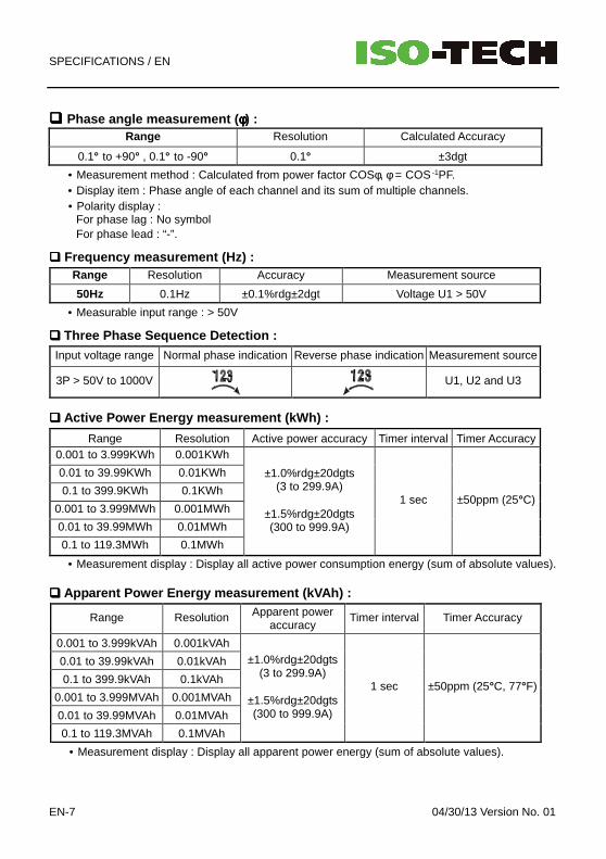
Phase angle measurement ( φφφφ) :Range Resolution Calculated Accuracy
0.1° to +90° , 0.1° to -90° 0.1° ±3dgt
• Measurement method : Calculated from power factor COSφ, φ = COS -1PF.
• Display item : Phase angle of each channel and its sum of multiple channels.• Polarity display :
For phase lag : No symbolFor phase lead : “-”.
Frequency measurement (Hz) :Range Resolution Accuracy Measurement source
50Hz 0.1Hz ±0.1%rdg±2dgt Voltage U1 > 50V
• Measurable input range : > 50V
Three Phase Sequence Detection :Input voltage range Normal phase indication Reverse phase indication Measurement source
3P > 50V to 1000V U1, U2 and U3
Active Power Energy measurement (kWh) :
Range Resolution Active power accuracy Timer interval Timer Accuracy0.001 to 3.999KWh 0.001KWh
0.01 to 39.99KWh 0.01KWh
0.1 to 399.9KWh 0.1KWh
0.001 to 3.999MWh 0.001MWh
0.01 to 39.99MWh 0.01MWh
0.1 to 119.3MWh 0.1MWh
±1.0%rdg±20dgts(3 to 299.9A)
±1.5%rdg±20dgts(300 to 999.9A)
1 sec ±50ppm (25°C)
• Measurement display : Display all active power consumption energy (sum of absolute values).
Apparent Power Energy measurement (kVAh) :
Range Resolution Apparent poweraccuracy
Timer interval Timer Accuracy
0.001 to 3.999kVAh 0.001kVAh
0.01 to 39.99kVAh 0.01kVAh
0.1 to 399.9kVAh 0.1kVAh
0.001 to 3.999MVAh 0.001MVAh
0.01 to 39.99MVAh 0.01MVAh
0.1 to 119.3MVAh 0.1MVAh
±1.0%rdg±20dgts(3 to 299.9A)
±1.5%rdg±20dgts(300 to 999.9A)
1 sec ±50ppm (25°C, 77°F)
• Measurement display : Display all apparent power energy (sum of absolute values).
SPECIFICATIONS / EN
04/30/13 Version No. 01 EN-8
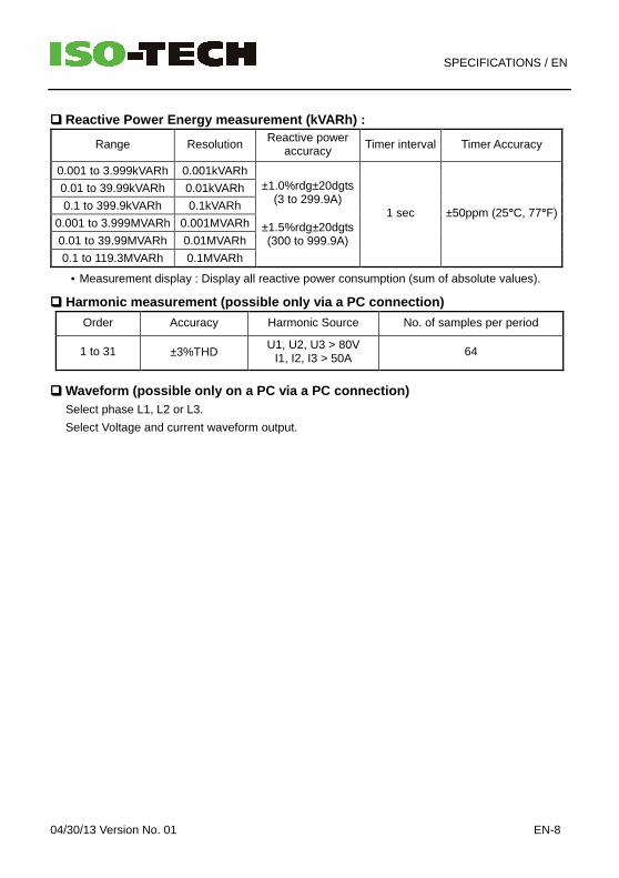
Reactive Power Energy measurement (kVARh) :
Range ResolutionReactive power
accuracy Timer interval Timer Accuracy
0.001 to 3.999kVARh 0.001kVARh
0.01 to 39.99kVARh 0.01kVARh
0.1 to 399.9kVARh 0.1kVARh
0.001 to 3.999MVARh 0.001MVARh
0.01 to 39.99MVARh 0.01MVARh
0.1 to 119.3MVARh 0.1MVARh
±1.0%rdg±20dgts(3 to 299.9A)
±1.5%rdg±20dgts(300 to 999.9A)
1 sec ±50ppm (25°C, 77°F)
• Measurement display : Display all reactive power consumption (sum of absolute values).
Harmonic measurement (possible only via a PC conne ction)
Order Accuracy Harmonic Source No. of samples per period
1 to 31 ±3%THDU1, U2, U3 > 80V
I1, I2, I3 > 50A64
Waveform (possible only on a PC via a PC connection )Select phase L1, L2 or L3.
Select Voltage and current waveform output.
PARTS & CONTROLS / EN
EN-9 04/30/13 Version No. 01
IV. PARTS & CONTROLS
4-1 Description of Parts & Control keys
U12 Y-M
Q
NO.
P
θ
I4
U3 m-s
S
U23 D-h
I3
I1
I4
I2
N
ⅢU1 U2 U3
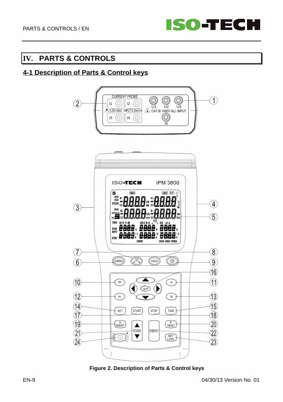
Figure 2. Description of Parts & Control keys
PARTS & CONTROLS / EN
04/30/13 Version No. 01 EN-10
1. Input for voltage terminals (U1, U2, U3, N).Note the 3 inputs are not galvanically isolated, they have the common reference point “N”(neutral)
2. Input sockets for current probes (I1, I2, I3, I4).
3. Plug for external AC adaptor power supply input.
CAUTION: Use only the mains adaptor supplied with the instrument
4. Optical USB interface output.
5. LCD display.
6. WIRING key : Press “WIRING” to select the type of electrical system under test:1P2W -To measure single-phase two-wire power lines1P3W -To measure single-phase three-wire power lines3P3W2M -To measure three-phase, three-wire power lines without neutral, usethis when measuring three-phase power with 2-current probe measurement only3P4W -To measure three-phase four-wire power lines with neutral
7. key : Phase sequence detection function key. In the 3P4W mode, press and hold down thiskey, it will display phase detection results as follows :
Normal phase
Reverse phase
8. HOLD key : Data hold function key, press “HOLD” key to hold data, the “ HOLD ” symbol isdisplayed, press “HOLD” key again to exit Hold function.
9. key : Backlight function key, press “ ” key to turn on and off the backlight. Thebacklight will switch off automatically after 30 seconds.
10. PF key : Display measured power factor value control key, the “PF” symbol is displayed.
11. Θ key : Display measured phase angle value control key, the “φφφφ” symbol is displayed.
12. Hz key : Display measured frequency value control key, the “Hz” symbol is displayed.
13. I4 key : Display measured I4 current probe value control key, the “I4” symbol is displayed.
14. SET key : Setting current date and time function key, press “SET” key to enter current timesetting mode and interval time setting mode for auto data logging use.
15 TIME key : Display current date and time control key, press and hold down “TIME” key todisplay the current data and time.
16. ↵↵↵↵ keys : Set current date and time, or recall manual data memory control keys
17. START key : Start auto data logging function.
18. STOP key : Stop auto data logging function. Press “START” key to resume recording incurrent data sets.
19. MEMORY key : Manual data memory control key. Press “MEMORY” key each time to storeone set of current display reading into the memory, the “M” symbol and thememory address number is displayed, total memory size is 99 sets.
20. READ key : Read manual memory data control key.
PARTS & CONTROLS / EN
EN-11 04/30/13 Version No. 01
21. POWER Key : Display measured power value control key, the Pt123, Qt123 and St123symbols will be displayed in cycles.
22. ENERGY key : Display total integrated power energy value control key.
23. KEY Lock key : Lock all the functions key, except and keys, the “LOCK ” symbol isdisplayed.
24. key : Power on-off control key.
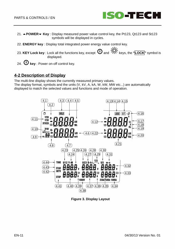
4-2 Description of DisplayThe multi-line display shows the currently measured primary values.The display format, symbols and the units (V, kV, A, kA, W, kW, MW etc...) are automaticallydisplayed to match the selected values and functions and mode of operation.
Q
NO.
P
U23 D-hU12 Y-M U3 m-s
S
4.14.2
4.3 4.4 4.5
4.6
4.11
4.10
4.9
4.8 4.7
4.234.24
4.25 4.264.27
4.304.314.29
4.28
4.41
4.38
4.40 4.39 4.37 4.36 4.35 4.34
4.32
4.33
4.44
4.43
4.42
4.184.17
4.19
4.20
4.14 4.15
4.16
4.13
4.21
4.22
4.12
Figure 3. Display Layout

PARTS & CONTROLS / EN
04/30/13 Version No. 01 EN-12
4.1 : Auto power off indication.4.2 P1 : Phase 1 active power measured display indicator.
P2 : Phase 2 active power measured display indicator.P3 : Phase 3 active power measured display indicator.Pt : Total active power measured display indicator and total active energy measured
display indicator.
4.3 HOLD : Display hold mode.
4.4 Display value of Active Power
4.5 KW: Active Power Unit: or KWh , MWh, active energy unit
4.6 Kvar: Reactive Power Unit or Kvarh , Mvarh reactive energy unit
4.7 Display of reactive Power4.8 Q1 : Phase 1 reactive power measured display indicator.
Q2 : Phase 2 reactive power measured display indicator.Q3 : Phase 3 reactive power measured display indicator.Qt : Total reactive power measured display indicator and total reactive energy
measured display indicator.4.9 DATA No.xx : Display of the measurement memory address
Manual data logging: displays the last saved measurement memory address(01 to 99 ).
Automatic Data Logger: Displays the last saved series of measurements (01 to 10 )
01 to 10 : Maximum 10 memory blocks can be use, only 12,000 sets of data can bestored in one block. A maximum of 20,000 sets data can be stored.
FF : Memory full indication if 10 memory blocks or 20,000 stored data sets isexceeded.
4.10 M : Manual data logged indication,
M flashes once when one set of data is stored in the memory.
The symbol is permanently displayed during active data logger recording and brieflyhidden when automatically saving.
R Manual data read indicator
4.11 1P2W : Measure single-phase two-wire power line indicator.
1P3W : Measure single-phase three-wire power line indicator.
3P3W2M : Measure three-phase three-wire power line indicator.
3P4W : Measure three-phase four-wire power line indicator.4.12 PF1 : Phase 1 power factor measured display.
PF2 : Phase 2 power factor measured display.PF3 : Phase 3 power factor measured display.PFt : Total power factor measured display.
4.13 Display value for Power Factor, Frequency & I4 current
4.14 LOCK : Keyboard lock indicator.
4.15 BT : Low battery indicator.
PARTS & CONTROLS / EN
EN-13 04/30/13 Version No. 01
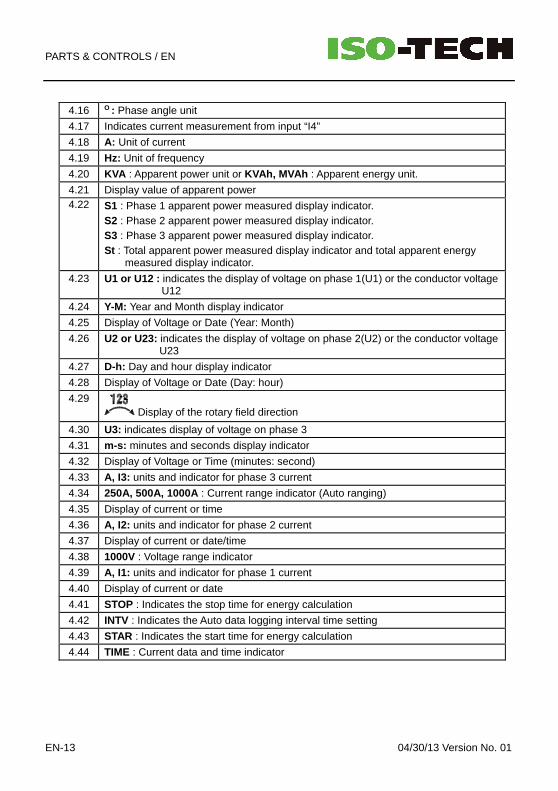
4.16 O : Phase angle unit
4.17 Indicates current measurement from input “I4”
4.18 A: Unit of current
4.19 Hz: Unit of frequency
4.20 KVA : Apparent power unit or KVAh, MVAh : Apparent energy unit.
4.21 Display value of apparent power4.22 S1 : Phase 1 apparent power measured display indicator.
S2 : Phase 2 apparent power measured display indicator.S3 : Phase 3 apparent power measured display indicator.St : Total apparent power measured display indicator and total apparent energy
measured display indicator.
4.23 U1 or U12 : indicates the display of voltage on phase 1(U1) or the conductor voltageU12
4.24 Y-M: Year and Month display indicator
4.25 Display of Voltage or Date (Year: Month)
4.26 U2 or U23: indicates the display of voltage on phase 2(U2) or the conductor voltageU23
4.27 D-h: Day and hour display indicator
4.28 Display of Voltage or Date (Day: hour)
4.29 Display of the rotary field direction
4.30 U3: indicates display of voltage on phase 3
4.31 m-s: minutes and seconds display indicator
4.32 Display of Voltage or Time (minutes: second)
4.33 A, I3: units and indicator for phase 3 current
4.34 250A, 500A, 1000A : Current range indicator (Auto ranging)
4.35 Display of current or time
4.36 A, I2: units and indicator for phase 2 current
4.37 Display of current or date/time
4.38 1000V : Voltage range indicator
4.39 A, I1: units and indicator for phase 1 current
4.40 Display of current or date
4.41 STOP : Indicates the stop time for energy calculation
4.42 INTV : Indicates the Auto data logging interval time setting
4.43 STAR : Indicates the start time for energy calculation
4.44 TIME : Current data and time indicator

OPERATING INSTRUCTIONS / EN
04/30/13 Version No. 01 EN-14
V. OPERATING INSTRUCTIONS
DANGER• Voltage input connectors U1 to, U2 & U3 are not galvanically isolated, they have the
common reference point “N” (neutral)• Only connect the necessary number of test leads and probes for the test.
WARNING• Always set up the measurement first, then connect the test leads and probes to the
instrument before connecting to the circuit under test• Connect the Neutral lead first, then the voltage leads and the current probe,
Disconnect in the reverse order.• Remove all test leads and probes that are not in use.
CAUTION• Where possible, isolate the power to the electrical circuit to be tested before
connecting the voltage test leads and current probes.
5-1 ICA 3600 AC Current Probe Connection
Safety Information• Read the operating instructions before using and follow all safety instructions.
• Use the current probe only as specified in the operating instructions, otherwise theinstruments safety features may not protect you.
• Adhere to local and national safety codes. Personal protective equipment must be used toprevent shock and arc blast injury where hazardous live conductors are exposed.
• Do not hold the current probe anywhere beyond the tactile barrier, see Figure 4. ICA 3600Current Probe
• Before each use, inspect the current probes. Look for cracks or missing portions of theclamp housing or output cable insulation. Also look for loose or weakened components.Pay particular attention to the insulation surrounding the jaws.
• Do not use damaged current probes.
• Never use the current probes on a circuit with voltages higher than 600V CAT III.
• Use extreme caution when working around bare conductor or bus bars, contact with theconductor could result in electric shock.
• Use caution with voltages above 30 Vac rms, 42 Vac peak, or 60 Vdc. These voltages posea shock hazard
• Use only the current probes supplied with the analyser.
CAUTION : Ensure the current probe is connected to the instrument before clampingaround a live conductor. Open current probe outputs can induce a highvoltage in the outputs that can be dangerous to the user and can lead todestruction of the current probe.

OPERATING INSTRUCTIONS / EN
EN-15 04/30/13 Version No. 01
(See Figure 1. Current Probe Positional Error and Figure 4. ICA 3600 Current Probe)
1. Connect the current probe to the instrument.
2. Connect the current probe jaws around the conductor to be measured
Centre the conductor inside the current probe jaw
Make sure the probe is perpendicular to the conductor
Ensure the arrow on the top of the probe faces towards the load of the circuit
For optimal reading, ensure that the conductor is positioned between the alignment markson the jaws of the current probe
Avoid taking measurements close to other current carrying conductors
Load Direction Arrow
Alignment Marks
Tactile Barrier
Figure 4. ICA 3600 Current Probe
OPERATING INSTRUCTIONS / EN
04/30/13 Version No. 01 EN-16
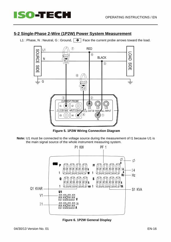
5-2 Single-Phase 2-Wire (1P2W) Power System Measure ment
L1 : Phase, N : Neutral, G : Ground, Face the current probe arrows toward the load.
U2
N
I3 I4
I1 I2U1Ⅲ
U3
Figure 5. 1P2W Wiring Connection Diagram
Note: U1 must be connected to the voltage source during the measurement of I1 because U1 isthe main signal source of the whole instrument measuring system.
SQ
U1
P
Figure 6. 1P2W General Display

OPERATING INSTRUCTIONS / EN
EN-17 04/30/13 Version No. 01
1. Press “ ” key to turn on the instrument.
2. Press “WIRING” key to select the 1P2W electrical system test, the “1P2W” symbol will bedisplayed.
3. Connect the voltage test leads and current probes to the instrument: Connect the black voltage test lead to the “N” terminal. Connect the red voltage test lead to the “U1” terminal. Connect the I1 current probe to the “I1” socket. To measure ground leakage current, connect the I4 current probe to the “I4” socket.
4. Connect the voltage test leads and current probes to the electrical equipment to be tested asshown in Figure 5. 1P2W Wiring Connection Diagram.
CAUTION: Where possible, isolate the power to the electrical circuit to be tested beforeconnecting the voltage test leads and current probes.
Connect the black voltage test alligator clip to the Neutral Line “N”. Connect the red voltage test alligator clip to phase “L1”. Clamp the I1 current probe securely around phase “L1”. To measure ground leakage current, clamp the I4 current probe securely around the Ground
Line “G” .
5. Frequency (Hz), Phase Angle (Θ), Ground Leakage Current (I4) and Power Factor (pF) measurement :
Hz : Press “Hz” key, PF1 will show “Hz” . Press “PF” key to exit.
Θ : Press “Θ” key, PF1 will show “ φφφφ” . Press “PF” key to exit.
I4 : Press “I4” key, PF1 will show “I4” . Press “PF” key to exit.
pF : Press “PF” key.
6. Energy measurement:
Press “ENERGY” key, the “Pt” , “Qt” , “St” and “PFt” or “ φφφφt” symbol are displayed and thestarting time of the energy measurement is displayed in the “STAR” line. The energy valuesand the current time will be displayed during the energy measurement.
a). KW displays KWh
b). KVAR displays KVARh
c). KVA displays KVAh
Press “STOP” key to stop and hold the energy measurements. The “ HOLD ” symbol isdisplayed and the final calculation time appears in the “STOP” line on the display.
Press “ ↵↵↵↵ ” key to exit the energy measurement mode and return to normal measurementmode.
OPERATING INSTRUCTIONS / EN
04/30/13 Version No. 01 EN-18
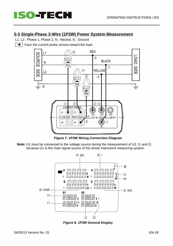
5-3 Single-Phase 3-Wire (1P3W) Power System Measure mentL1, L2 : Phase 1, Phase 2, N : Neutral, G : Ground
Face the current probe arrows toward the load
I3 I4
I1 I2
N
U2U1Ⅲ
U3
Figure 7. 1P3W Wiring Connection Diagram
Note: U1 must be connected to the voltage source during the measurement of U2, I1 and I2,because U1 is the main signal source of the whole instrument measuring system.
P
U1
Q
U2
S
Figure 8. 1P3W General Display

OPERATING INSTRUCTIONS / EN
EN-19 04/30/13 Version No. 01
1. Press “ ” key to turn on the instrument.
2. Press “WIRING” key to select the 1P3W electrical system test, the “1P3W” symbol will bedisplayed.
3. Connect the voltage test leads and current probes to the instrument : Connect the black voltage test lead to the “N” terminal. Connect the red voltage test lead to the “U1” terminal. Connect the yellow voltage test lead to the “U2” terminal. Connect the I1 current probe to the “I1” socket. Connect the I2 current probe to the “I2” socket. To measure ground leakage current, connect the I4 current probe output plug to the “I4”
socket.
4. Connect the voltage test leads and current probes to the electrical equipment to be tested asshown in Figure 7. 1P3W Wiring Connection Diagram.
CAUTION: Where possible, isolate the power to the electrical circuit to be tested beforeconnecting the voltage test leads and current probes
Connect the black voltage test alligator clip to the neutral conductor “N”.
Connect the red voltage test alligator clip to Phase 1 “L1”.
Connect the yellow voltage test alligator clip to Phase 2 “L2”.
Clamp the I1 current probe securely around Phase 1 “L1”.
11 Clamp the I2 current probe securely around Phase 2 “L2”.
12 To measure ground leakage current, clamp the I4 current probe securely around the groundline “G”.
5. Press “ POWER” key to select between Phase 1 (P1, Q1, S1, PF1), Phase 2 (P2, Q2, S2,PF2) and total (Pt, Qt, St, PFt) measured values.
6. Frequency (Hz), Phase Angle (Θ), Ground Leakage Current (I4) and Power Factor (pF)measurement:
Hz : Press “Hz” key, PF1 will show “Hz” . Press “PF ” key to exit.
Θ : Press “Θ” key, PF1 will show “ φφφφ” . Press “PF” key to exit.
I4 : Press “I4” key, PF1 will show “I4” . Press “PF” key to exit.
pF : Press “PF” key.
7. Energy measurement:
Press “ENERGY” key, the “Pt”, “Qt”, “St” and “PFt” or “φ t” symbol are displayed and thestarting time of the energy measurement is displayed in the “STAR” line. The energy valuesand the current time will be displayed during the energy measurement.
a). KW displays KWh
b). KVAR displays KVARh
c). KVA displays KVAh
OPERATING INSTRUCTIONS / EN
04/30/13 Version No. 01 EN-20
Press “STOP” key to stop and hold the energy measurements. The “ HOLD ” symbol isdisplayed and the final calculation time appears in the “STOP” line on the display.
Press “ ↵↵↵↵ ” key to exit the energy measurement mode and return to normal measurementmode.
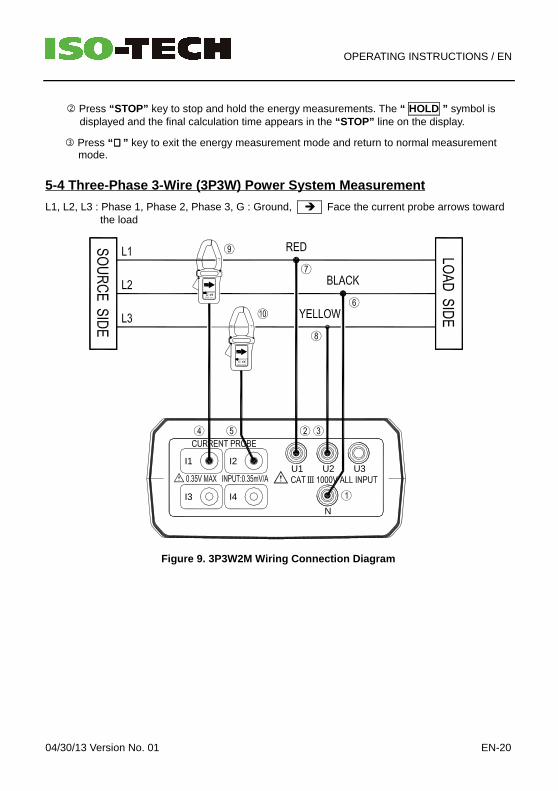
5-4 Three-Phase 3-Wire (3P3W) Power System Measurem ent
L1, L2, L3 : Phase 1, Phase 2, Phase 3, G : Ground, Face the current probe arrows towardthe load
U2
I4I3
N
I1 I2U1Ⅲ
U3
Figure 9. 3P3W2M Wiring Connection Diagram
OPERATING INSTRUCTIONS / EN
EN-21 04/30/13 Version No. 01
S
U23
Q
U12
P
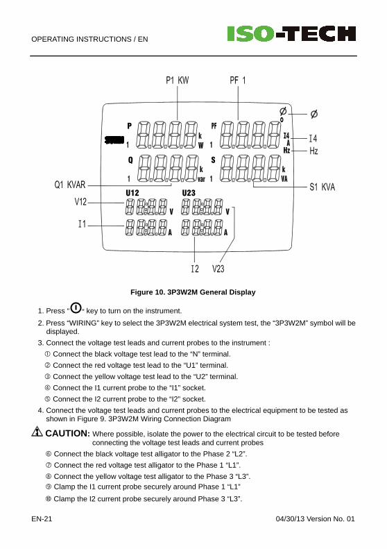
Figure 10. 3P3W2M General Display
1. Press “ ” key to turn on the instrument.
2. Press “WIRING” key to select the 3P3W2M electrical system test, the “3P3W2M” symbol will bedisplayed.
3. Connect the voltage test leads and current probes to the instrument :
Connect the black voltage test lead to the “N” terminal.
Connect the red voltage test lead to the “U1” terminal.
Connect the yellow voltage test lead to the “U2” terminal.
Connect the I1 current probe to the “I1” socket.
Connect the I2 current probe to the “I2” socket.
4. Connect the voltage test leads and current probes to the electrical equipment to be tested asshown in Figure 9. 3P3W2M Wiring Connection Diagram
CAUTION: Where possible, isolate the power to the electrical circuit to be tested beforeconnecting the voltage test leads and current probes
Connect the black voltage test alligator to the Phase 2 “L2”.
Connect the red voltage test alligator to the Phase 1 “L1”.
Connect the yellow voltage test alligator to the Phase 3 “L3”. Clamp the I1 current probe securely around Phase 1 “L1”
Clamp the I2 current probe securely around Phase 3 “L3”.
OPERATING INSTRUCTIONS / EN
04/30/13 Version No. 01 EN-22
5. Press “POWER” key to select between Phase 1(P1, Q1, S1, PF1), Phase 2 (P2, Q2, S2,PF2) and total (Pt, Qt, St, PFt) measured values.
6. Frequency (Hz), Phase Angle (Θ) and Power Factor (pF) measurement: Hz : Press “Hz” key, PF1 will show “Hz”. Press “PF” key to exit.
Θ : Press “Θ” key, PF1 will show “φ”. Press “PF” key to exit.
pF : Press “PF” key.
7. Energy measurement:
Press “ENERGY” key; the “Pt”, “Qt”, “St” and “PFt” or “φt” symbol are displayed and thestarting time of the energy measurement is displayed in the “STAR” line. The energy valuesand the current time will be displayed during the energy measurement.
a). KW displays KWhb). KVAR displays KVARhc). KVA displays KVAh
Press “STOP” key to stop and hold the energy measurements. The “HOLD” symbol isdisplayed and the final calculation time appears in the “STOP” line on the display.
Press “↵↵↵↵ ” key to exit the energy measurement mode and return to normal measurementmode.
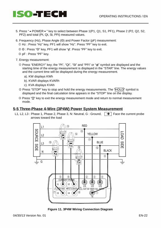
5-5 Three-Phase 4-Wire (3P4W) Power System Measurem entL1, L2, L3 : Phase 1, Phase 2, Phase 3, N: Neutral, G : Ground, Face the current probe
arrows toward the load
I4I3
I1 I2
N
U1 U2Ⅲ
U3
Figure 11. 3P4W Wiring Connection Diagram
OPERATING INSTRUCTIONS / EN
EN-23 04/30/13 Version No. 01
P
U1
Q
U2
S
U3
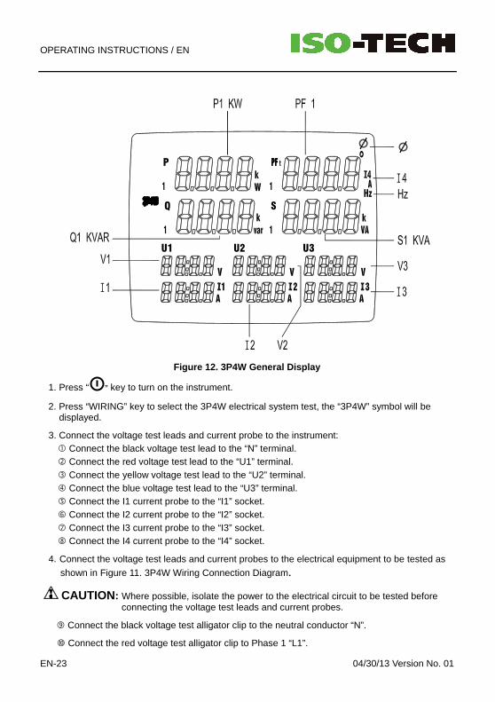
Figure 12. 3P4W General Display
1. Press “ ” key to turn on the instrument.
2. Press “WIRING” key to select the 3P4W electrical system test, the “3P4W” symbol will bedisplayed.
3. Connect the voltage test leads and current probe to the instrument: Connect the black voltage test lead to the “N” terminal. Connect the red voltage test lead to the “U1” terminal. Connect the yellow voltage test lead to the “U2” terminal. Connect the blue voltage test lead to the “U3” terminal. Connect the I1 current probe to the “I1” socket. Connect the I2 current probe to the “I2” socket. Connect the I3 current probe to the “I3” socket. Connect the I4 current probe to the “I4” socket.
4. Connect the voltage test leads and current probes to the electrical equipment to be tested as
shown in Figure 11. 3P4W Wiring Connection Diagram.
CAUTION: Where possible, isolate the power to the electrical circuit to be tested beforeconnecting the voltage test leads and current probes.
Connect the black voltage test alligator clip to the neutral conductor “N”.
Connect the red voltage test alligator clip to Phase 1 “L1”.
OPERATING INSTRUCTIONS / EN
04/30/13 Version No. 01 EN-24
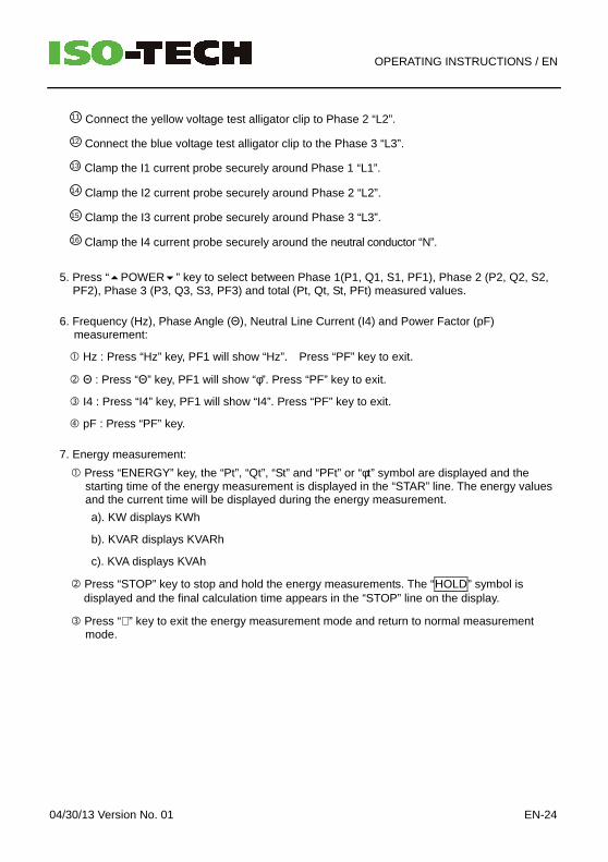
11 Connect the yellow voltage test alligator clip to Phase 2 “L2”.
12 Connect the blue voltage test alligator clip to the Phase 3 “L3”.
13 Clamp the I1 current probe securely around Phase 1 “L1”.
14 Clamp the I2 current probe securely around Phase 2 “L2”.
15 Clamp the I3 current probe securely around Phase 3 “L3”.
16 Clamp the I4 current probe securely around the neutral conductor “N”.
5. Press “POWER” key to select between Phase 1(P1, Q1, S1, PF1), Phase 2 (P2, Q2, S2,PF2), Phase 3 (P3, Q3, S3, PF3) and total (Pt, Qt, St, PFt) measured values.
6. Frequency (Hz), Phase Angle (Θ), Neutral Line Current (I4) and Power Factor (pF)measurement:
Hz : Press “Hz” key, PF1 will show “Hz”. Press “PF” key to exit.
Θ : Press “Θ” key, PF1 will show “φ”. Press “PF” key to exit.
I4 : Press “I4” key, PF1 will show “I4”. Press “PF” key to exit.
pF : Press “PF” key.
7. Energy measurement:
Press “ENERGY” key, the “Pt”, “Qt”, “St” and “PFt” or “φt” symbol are displayed and thestarting time of the energy measurement is displayed in the “STAR” line. The energy valuesand the current time will be displayed during the energy measurement.
a). KW displays KWh
b). KVAR displays KVARh
c). KVA displays KVAh
Press “STOP” key to stop and hold the energy measurements. The “HOLD” symbol isdisplayed and the final calculation time appears in the “STOP” line on the display.
Press “↵” key to exit the energy measurement mode and return to normal measurementmode.
OPERATING INSTRUCTIONS / EN
EN-25 04/30/13 Version No. 01
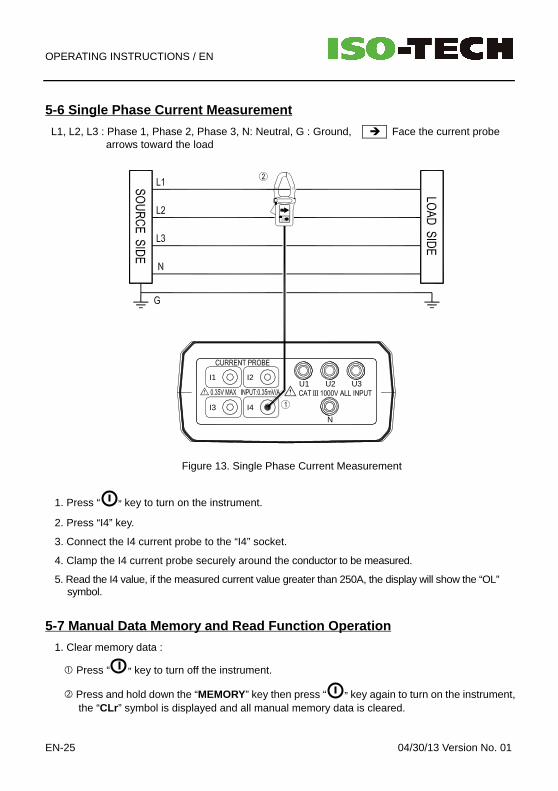
5-6 Single Phase Current Measurement
L1, L2, L3 : Phase 1, Phase 2, Phase 3, N: Neutral, G : Ground, Face the current probearrows toward the load
I3
I1
I4
I2
N
U1 U2Ⅲ
U3
Figure 13. Single Phase Current Measurement
1. Press “ ” key to turn on the instrument.
2. Press “I4” key.
3. Connect the I4 current probe to the “I4” socket.
4. Clamp the I4 current probe securely around the conductor to be measured.
5. Read the I4 value, if the measured current value greater than 250A, the display will show the “OL”symbol.
5-7 Manual Data Memory and Read Function Operation
1. Clear memory data :
Press “ ” key to turn off the instrument.
Press and hold down the “MEMORY” key then press “ ” key again to turn on the instrument,the “CLr ” symbol is displayed and all manual memory data is cleared.

OPERATING INSTRUCTIONS / EN
04/30/13 Version No. 01 EN-26
2. Store individual measurement data to memory :
Press “MEMORY” key once to store one set of displayed data to memory, the “M” symboldisplays once and the stored memory address will be displayed.
Maximum store memory capacity size is 99 sets.
3. Read the manually stored data :
Press “READ” key to enter the read mode, the “R” symbol is displayed.
Press “” and “” keys to read the stored data, the data address will be displayed.
Press “↵↵↵↵” key to exit the read mode.
5-8 Auto Data logging Function Operation1. Clear memory data:
Please refer to the software manual on the CD-ROM, use the PC to clear data logging readings,before starting a new recording session.
2. Store Auto data logging data to memory: Setting the current time and Auto data logging interval time: Press “SET” key to enter current time setting mode. Press “”, “”, “” and “” keys to set the current YEAR-month, DAY-hour and minute-
seconds. Press “↵↵↵↵” key to enter auto data logging interval time setting, the “INTV” symbol is displayed. Press “” and “” keys to select either 5 seconds, 30 seconds, 1 minute or 2 minute interval
time. Press “↵↵↵↵ ” key to exit TIME setting mode.
3. Enter Auto data logging mode. Press “START” key to start Auto data logging, “DATA M xx” will be displayed, the “ M ”
symbol,will display each time one set of data is stored into the memory.
Press “STOP” key to stop recording data, press “START” key to resume recording data.A maximum of 10 measurement blocks can be stored, with a maximum of 12000 measurementvalues stored within one block. The total maximum record capacity size is 20,000 sets of data.
When the maximum block or maximum capacity is full, the “FF” symbol will be displayed anddata recording is automatically stopped.
4. Download data to PCPlease refer to the software manual (CD-ROM) to download the data.
OPERATING INSTRUCTIONS / EN
EN-27 04/30/13 Version No. 01
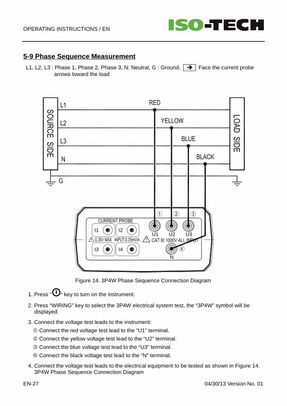
5-9 Phase Sequence Measurement
L1, L2, L3 : Phase 1, Phase 2, Phase 3, N: Neutral, G : Ground, Face the current probearrows toward the load
I4I3
I1 I2
N
U1 U2Ⅲ
U3
Figure 14. 3P4W Phase Sequence Connection Diagram
1. Press “ ” key to turn on the instrument.
2. Press “WIRING” key to select the 3P4W electrical system test, the “3P4W” symbol will bedisplayed.
3. Connect the voltage test leads to the instrument:
Connect the red voltage test lead to the “U1” terminal.
Connect the yellow voltage test lead to the “U2” terminal.
Connect the blue voltage test lead to the “U3” terminal.
Connect the black voltage test lead to the “N” terminal.
4. Connect the voltage test leads to the electrical equipment to be tested as shown in Figure 14.3P4W Phase Sequence Connection Diagram
OPERATING INSTRUCTIONS / EN
04/30/13 Version No. 01 EN-28
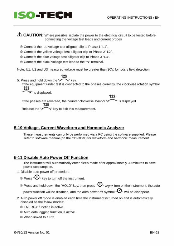
CAUTION: Where possible, isolate the power to the electrical circuit to be tested beforeconnecting the voltage test leads and current probes
Connect the red voltage test alligator clip to Phase 1 “L1”.
Connect the yellow voltage test alligator clip to Phase 2 “L2”.
Connect the blue voltage test alligator clip to Phase 3 “L3”.
Connect the black voltage test lead to the “N” terminal.
Note. U1, U2 and U3 measured voltage must be greater than 30V, for rotary field detection
5. Press and hold down the “ ” key.If the equipment under test is connected to the phases correctly, the clockwise rotation symbol
“ ” is displayed.
If the phases are reversed, the counter clockwise symbol “ ” is displayed.
Release the “ ” key to exit this measurement.
5-10 Voltage, Current Waveform and Harmonic Analyze r
These measurements can only be performed via a PC using the software supplied. Pleaserefer to software manual (on the CD-ROM) for waveform and harmonic measurement.
5-11 Disable Auto Power Off FunctionThe instrument will automatically enter sleep mode after approximately 30 minutes to savepower consumption.
1. Disable auto power off procedure:
Press “ ” key to turn off the instrument.
Press and hold down the “HOLD” key, then press “ ” key to turn on the instrument, the auto
power function will be disabled, and the auto power off symbol “ ” will be disappear.
2. Auto power off mode is enabled each time the instrument is turned on and is automaticallydisabled as the follow modes:
ENERGY function is active.
Auto data logging function is active.
When linked to a PC.

MAINTENANCE / EN
EN-29 04/30/13 Version No. 01
VI. MAINTENANCE
6-1 General Maintenance
1. Repairs or services that are not covered in this manual should only be performed by qualifiedpersonnel.
2. Clean the instrument and accessories with a damp cloth and a mild soap. Do not use abrasives,solvent, or alcohol.
3. It is recommended to open the jaws of the current probe and wipe the magnetic pole pieceswith a lightly oiled cloth. This is to avoid rust or corrosion forming on the magnetic poles.
6-2 Battery Replacement
WARNING• To avoid electric shock, disconnect the test leads and current probes before replacing the
batteries.
• When replacing the batteries, do not mix batteries of different types or old and new batteries.
• Check the battery polarity carefully when inserting the batteries.
• Do not short-circuit used batteries, disassemble them, or throw them in a fire, doing so maycause the batteries to explode.
• Dispose of the used batteries in accordance with local regulations.
1. If the battery power is not sufficient, the LCD will display the “ BT ” symbol and replacement ofthe batteries is required.
2. Disconnect all test leads and current probe from any power electrical source, press “ ” key toturn off the instrument, and remove the test leads from the sockets.
3. The battery cover is secured to the bottom case by two screws, remove the two screws from thebottom case.
4. Remove battery cover, take out the batteries and replace with new batteries, observe thecorrect battery polarity.
5. Close the battery cover and refit the securing screws

SOFTWARE INSTALLATION AND OPERATION / EN
04/30/13 Version No. 01 EN-30
VII. SOFTWARE INSTALLATION AND OPERATION
For the detailed instructions, please refer to the content of the CD-ROM, which has thecomplete instructions for the software operation and relevant information.


![Index [docs-europe.electrocomponents.com]docs-europe.electrocomponents.com/webdocs/134b/0900766b8134bb17.pdfIndex by product group Technical Info ... S1-M2-02 + Single trigger + 2](https://img.pdfslide.us/doc/110x75/5adcde717f8b9a1a088c933f/index-docs-docs-by-product-group-technical-info-s1-m2-02-single-trigger.jpg)


![Untitled Document [docs-europe.electrocomponents.com]docs-europe.electrocomponents.com/webdocs/0920/0900766b809201d… · Schneider Electric Brands ZELIO-CONTROL Measurement Relays](https://img.pdfslide.us/doc/110x75/5abeae277f8b9a5d718d478e/untitled-document-docs-docs-schneider-electric-brands-zelio-control-measurement.jpg)