Embed Size (px)
Citation preview
Technical Data
PowerFlex 520-Series AC Drive SpecificationsOriginal Instructions
Drive Features: AppView™, CustomView™, QuickView™, and MainsFree™ configuration and programming tools.
Topic Page
Product Overview 2
Catalog Number Explanation 8
Technical Specifications 9
Environmental Specifications 12
Certifications 13
Dimensions and Weights 14
Design Considerations 16
Fuses and Circuit Breaker Ratings 27
Accessories and Dimensions 36
Safe-Torque-Off Function 46
Additional Resources 51
PowerFlex 520-Series AC Drive Specifications
Product Overview
The PowerFlex® 520-Series AC drive delivers an innovative design that is remarkably versatile and can accommodate systems ranging from standalone machines to simple system integration. The PowerFlex 523 drive provides general purpose control for applications ranging up to 30 HP and 22 kW. The PowerFlex 525 drive provides maximum flexibility and performance ranging up to 30 HP and 22 kW.
By combining a variety of motor control options, communications, energy savings and standard safety features in a cost-effective drive, the PowerFlex 520-Series drive is suitable for a wide array of applications.
Maximize your system performance and productivity by taking advantage of the following key features offered in a PowerFlex 520-Series drive.
PowerFlex 520-Series AC Drives Feature
Modular Design• Detachable control module and power module allow simultaneous configuration and installation.• Each drive has a standard control module used across the entire power range.• MainsFree™ configuration allows you to simply connect your control module to a PC with a standard USB cable
and quickly upload, download, and flash the drive with new settings.• Support for accessory cards without affecting footprint.
(PowerFlex 523 drives support one, PowerFlex 525 drives support two)
Packaging and Mounting• Installation can be quick and easy using the DIN rail mounting feature on A, B, and C frame drives. Panel mounting
is also available, providing added flexibility.• Zero Stacking™ is allowed for ambient temperatures up to 45 °C, saving valuable panel space.• Integral filtering is available on all 200V and 400V ratings, providing a cost-effective means of meeting EN61800-3
Category C2 and C3 EMC requirements. External filters provide compliance to EN61800-3 Category C1, C2, and C3 EMC requirements for all PowerFlex 520-Series ratings.
• An optional IP 30, NEMA/UL Type 1 conduit box is easily adapted to the standard IP 20 (NEMA Type Open) product, providing increased environmental ratings.
Optimized Performance• Removable MOV to ground provides trouble-free operation when used on ungrounded distribution systems.• A relay pre-charge limits inrush current.• Integral brake transistor, available on all ratings, provides dynamic braking capability with simple low cost brake
resistors.• A jumper to switch between 24V DC sink or source control for control wiring flexibility.• Dual Overload Rating available for drives above 15 HP/11 kW. Normal duty: 110% overload for 60 seconds or
150% for 3 seconds. Heavy duty: 150% overload for 60 seconds or 180% overload (200% programmable) for 3 seconds provides robust overload protection.
• Adjustable PWM frequency up to 16 kHz ensures quiet operation.
2 Rockwell Automation Publication 520-TD001D-EN-E - January 2014
PowerFlex 520-Series AC Drive Specifications
PowerFlex 520-Series AC Drive Advanced Features
Control Performance• Variety of motor control options, including:
• Volts per hertz (V/Hz)• Sensorless Vector Control (SVC)• Closed loop velocity vector control (PowerFlex 525 drives only)
• Variety of Positioning Control, including:• PointStop™ stops motor load in a consistent position without encoder feedback• Closed loop feedback with an optional encoder card (PowerFlex 525 drives only)• Point-to-point positioning mode (PowerFlex 525 drives only)
• Integral PID functionality enhances application flexibility(PowerFlex 523 drives have one PID loop, PowerFlex 525 drives have two PID loops)
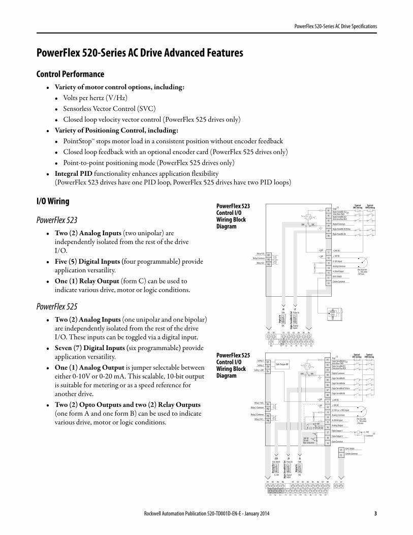
I/O Wiring
PowerFlex 523• Two (2) Analog Inputs (two unipolar) are
independently isolated from the rest of the driveI/O.
• Five (5) Digital Inputs (four programmable) provide application versatility.
• One (1) Relay Output (form C) can be used to indicate various drive, motor or logic conditions.
PowerFlex 525• Two (2) Analog Inputs (one unipolar and one bipolar)
are independently isolated from the rest of the driveI/O. These inputs can be toggled via a digital input.
• Seven (7) Digital Inputs (six programmable) provide application versatility.
• One (1) Analog Output is jumper selectable between either 0-10V or 0-20 mA. This scalable, 10-bit output is suitable for metering or as a speed reference for another drive.
• Two (2) Opto Outputs and two (2) Relay Outputs (one form A and one form B) can be used to indicate various drive, motor or logic conditions.
04
05
06
07
01
02
03
08
11
12
13
14
15
16
17
18
19
Digital Common
DigIn TermBlk 05
DigIn TermBlk 06
DigIn TermBlk 07/Pulse
Stop (1)
DigIn TermBlk 02/Start/Run FWD (2)
DigIn TermBlk 03/Direction/Run REV
DigIn TermBlk 08
R1
R2
S1
S2
S+
Relay 1 N.O.
Relay 1 Common
+24V DC
+10V DC
0-10V (or ±10V) Input
Analog Common
4-20mA Input
Analog Output
Opto Output 1
Opto Output 2
RJ45 Shield
Comm Common
Opto Common
+24V
+10V
Safety 1
Safety 2
Safety +24V
TypicalSNK wiring
TypicalSRC wiring
R1
S1 S2 S+ 11 12 13 14 15 16 17 18 19
R2 R5 R6 01 02 03 04 05 06 07 08 C1 C2
30V DC50 mANon-inductive
Common24V
(3)
Pot must be1...10 k ohm2 W min.0-10V
0/4-20 mA
SNK
Digi
tal I
n
DigI
n Te
rmBl
k 07 S
el
Anal
og O
ut
J10 J9 J5Pulse In
SRCDigitalInput
0/4-20mA
0-10V
SRCSNK
R5
R6
Relay 2 Common
Relay 2 N.C.
C1
C2
Safe-Torque-Off
04
05
06
01
02
03
11
12
13
14
15
C1
C2
Digital Common
DigIn TermBlk 05/Pulse
DigIn TermBlk 06
Stop (1)
DigIn TermBlk 02/Start/Run FWD (2)
DigIn TermBlk 03/Direction/Run REV
R1
R2
Relay N.O.
Relay Common
+24V DC
+10V DC
0-10V Input
Analog Common
4-20mA Input
RJ45 Shield
Comm Common
+24V
+10V
TypicalSNK wiring
TypicalSRC wiring
R1
11 12 13 14 15 C1 C2
R2
R3
01 02 03 04 05 06
Pot must be1...10 k ohm2 W min.
SNK
Digi
tal I
n
DigI
n Te
rmBl
k 05 S
el
J7J8Pulse In
SRC DigitalInput
SRCSNK
R3Relay N.C.
81
RS485(DSI)
PowerFlex 523 Control I/O Wiring Block Diagram
PowerFlex 525 Control I/O Wiring Block Diagram
Rockwell Automation Publication 520-TD001D-EN-E - January 2014 3
PowerFlex 520-Series AC Drive Specifications
Communications• Embedded EtherNet/IP™ port allows easy configuration, control, and collection of drive data over the network.
(PowerFlex 525 drives only)• Dual port EtherNet/IP option card supports Device Level Ring (DLR) topologies, providing fault-tolerant
connectivity for optimum drive availability.• Integral RS485/DSI communications enable the drives to be used in a multi-drop network configuration.• Optional communication cards such as DeviceNet™, and PROFIBUS DP™ can improve machine performance.• Online EDS file creation with RSNetWorx™ providing ease of set-up on a network.
Optimized for Common DC Bus Installations
Enhanced Control of Internal Pre-charge
Common DC Bus offers additional inherent breaking capabilities by utilizing all the drives/loads on the bus for energy absorption offering higher efficiency and cost savings. The PowerFlex 520-Series drive has been optimized for use in Common DC Bus or Shared DC Bus installations.
• Configurable pre-charge control using digital inputs.• Direct DC Bus connection to power terminal blocks.
Improved Ride Through
Operation Down to 1/2 Line Voltage
The PowerFlex 520-Series drive allows for the selection of 1/2 DC Bus operation, for use in critical applications where continued drive output is desired even in the event of brown out or low voltage conditions. The PowerFlex 520-Series drive also supports enhanced inertia ride through for additional low voltage mitigation.
• Selectable 1/2 line voltage operation.• Increased power loss ride through.
4 Rockwell Automation Publication 520-TD001D-EN-E - January 2014
PowerFlex 520-Series AC Drive Specifications
Additional Features of PowerFlex 525 Drives
Closed Loop Feedback
Encoder/Pulse Train Input
The PowerFlex 525 drive allows for configurable closed loop control with an optional encoder card for either speed or position feedback for improved speed regulation, basic position control, or other pulse inputs for motor control.
• Improved speed regulation• Basic position control
Basic Position Control
Local Position Control• Position regulator with StepLogic™
• 8 positions (local logic)
Outer Position Control Loop• Analog input bipolar mode offers improved zero-cross performance.• Simple motion control applications with more complex position profiles.• Speed reference supplied to drive via Analog Input or multiple field bus network options.• Speed ratio available for simple draw applications.
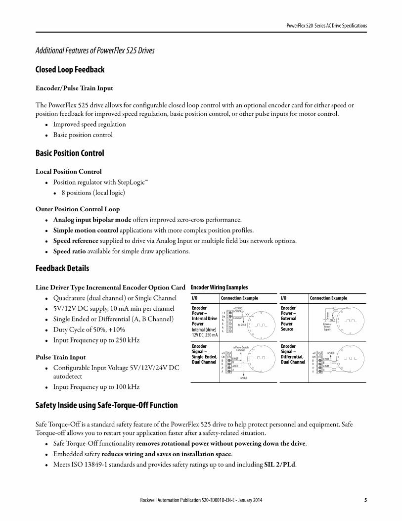
Feedback Details
Line Driver Type Incremental Encoder Option Card• Quadrature (dual channel) or Single Channel• 5V/12V DC supply, 10 mA min per channel• Single Ended or Differential (A, B Channel)• Duty Cycle of 50%, +10%• Input Frequency up to 250 kHz
Pulse Train Input• Configurable Input Voltage 5V/12V/24V DC
autodetect• Input Frequency up to 100 kHz
Safety Inside using Safe-Torque-Off Function
Safe Torque-Off is a standard safety feature of the PowerFlex 525 drive to help protect personnel and equipment. Safe Torque-off allows you to restart your application faster after a safety-related situation.
• Safe Torque-Off functionality removes rotational power without powering down the drive.• Embedded safety reduces wiring and saves on installation space.• Meets ISO 13849-1 standards and provides safety ratings up to and including SIL 2/PLd.
I/O Connection Example I/O Connection Example
EncoderPower –Internal DrivePowerInternal (drive)12V DC, 250 mA
EncoderPower –ExternalPowerSource
EncoderSignal – Single-Ended,Dual Channel
EncoderSignal –Differential,Dual Channel
Common
+12V DC(250 mA)
AA-BB-Cm+V
to SHLD+ Co
mmon
ExternalPowerSupply
toSHLD
A NOTA
BB NOT
to SHLD
to Power SupplyCommon
AA-BB-Cm+V to SHLD
A NOTB
A
B NOT
AA-BB-Cm+V
Encoder Wiring Examples
Rockwell Automation Publication 520-TD001D-EN-E - January 2014 5
PowerFlex 520-Series AC Drive Specifications
Communications and Software
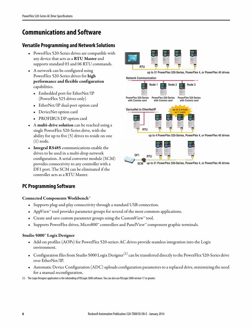
Versatile Programming and Network Solutions• PowerFlex 520-Series drives are compatible with
any device that acts as a RTU Master and supports standard 03 and 06 RTU commands.
• A network can be configured using PowerFlex 520-Series drives for high performance and flexible configuration capabilities.• Embedded port for EtherNet/IP
(PowerFlex 525 drives only)• EtherNet/IP dual-port option card• DeviceNet option card• PROFIBUS DP option card
• A multi-drive solution can be reached using a single PowerFlex 520-Series drive, with the ability for up to five (5) drives to reside on one (1) node.
• Integral RS485 communications enable the drives to be used in a multi-drop network configuration. A serial converter module (SCM) provides connectivity to any controller with a DF1 port. The SCM can be eliminated if the controller acts as a RTU Master.
PC Programming Software
Connected Components Workbench™• Supports plug-and-play connectivity through a standard USB connection.• AppView™ tool provides parameter groups for several of the most common applications.• Create and save custom parameter groups using the CustomView™ tool.• Supports PowerFlex drives, Micro800™ controllers and PanelView™ component graphic terminals.
Studio 5000™ Logix Designer• Add-on profiles (AOPs) for PowerFlex 520-seriers AC drives provide seamless integration into the Logix
environment.
• Configuration files from Studio 5000 Logix Designer(1) can be transferred directly to the PowerFlex 520-Series drive over EtherNet/IP.
• Automatic Device Configuration (ADC) uploads configuration parameters to a replaced drive, minimizing the need for a manual reconfiguration.
(1) The Logix Designer application is the rebranding of RSLogix 5000 software. You can also use RSLogix 5000 version 17 or greater.
DeviceNet to EtherNet/IP
RTU
RTU
Network Communication
Node 1 Node 2 Node 3
up to 4 PowerFlex 520-Series, PowerFlex 4, or PowerFlex 40 drives
up to 31 PowerFlex 520-Series, PowerFlex 4, or PowerFlex 40 drives
up to 31 PowerFlex 520-Series, PowerFlex 4, or PowerFlex 40 drives
RTU
SCM
DF1
PowerFlex 520-Serieswith Comms card
PowerFlex 520-Serieswith Comms card
PowerFlex 520-Serieswith Comms card
6 Rockwell Automation Publication 520-TD001D-EN-E - January 2014
PowerFlex 520-Series AC Drive Specifications
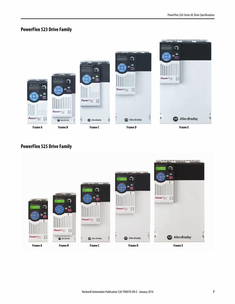
PowerFlex 523 Drive Family
PowerFlex 525 Drive Family
Frame A Frame B Frame C Frame D Frame E
Frame A Frame B Frame C Frame D Frame E
Rockwell Automation Publication 520-TD001D-EN-E - January 2014 7

PowerFlex 520-Series AC Drive Specifications
Catalog Number Explanation
Code Type25A PowerFlex 52325B PowerFlex 525
(1) This rating is only available for PowerFlex 523 drives.(2) Normal and Heavy Duty ratings are available for this drive.
1-3 4 5 6-8 9 10 11 12 13 14
25B – B 2P3 N 1 1 4 – –Drive Dash Voltage Rating Rating Enclosure Reserved Emission Class Reserved Dash Dash
Output Current @ 3 Phase, 380...480V InputCode Amps Fram
eND HDHP kW HP kW
1P4 1.4 A 0.5 0.4 0.5 0.42P3 2.3 A 1.0 0.75 1.0 0.754P0 4.0 A 2.0 1.5 2.0 1.56P0 6.0 A 3.0 2.2 3.0 2.2010 10.5 B 5.0 4.0 5.0 4.0013 13.0 C 7.5 5.5 7.5 5.5017 17.0 C 10.0 7.5 10.0 7.5024 24.0 D 15.0 11.0 15.0 11.0030(2) 30.0 D 20.0 15.0 15.0 11.0037(2) 37.0 E 25.0 18.5 20.0 15.0043(2) 43.0 E 30.0 22.0 25.0 18.5
Output Current @ 3 Phase, 525...600V InputCode Amps Fram
eND HDHP kW HP kW
0P9 0.9 A 0.5 0.4 0.5 0.41P7 1.7 A 1.0 0.75 1.0 0.753P0 3.0 A 2.0 1.5 2.0 1.54P2 4.2 A 3.0 2.2 3.0 2.26P6 6.6 B 5.0 4.0 5.0 4.09P9 9.9 C 7.5 5.5 7.5 5.5012 12.0 C 10.0 7.5 10.0 7.5019 19.0 D 15.0 11.0 15.0 11.0022(2) 22.0 D 20.0 15.0 15.0 11.0027(2) 27.0 E 25.0 18.5 20.0 15.0032(2) 32.0 E 30.0 22.0 25.0 18.5
Code Voltage PhaseV 120V AC 1A 240V AC 1B 240V AC 3D 480V AC 3E 600V AC 3
Code EnclosureN IP20 NEMA / Open
Code Interface Module1 Standard
Code EMC Filter0 No Filter1 Filter
Code Braking4 Standard
Output Current @ 1 Phase, 100...120V InputCode Amps Frame ND HD
HP kW HP kW1P6(1) 1.6 A 0.25 0.2 0.25 0.22P5 2.5 A 0.5 0.4 0.5 0.44P8 4.8 B 1.0 0.75 1.0 0.756P0 6.0 B 1.5 1.1 1.5 1.1
Output Current @ 1 Phase, 200...240V InputCode Amps Frame ND HD
HP kW HP kW1P6(1) 1.6 A 0.25 0.2 0.25 0.22P5 2.5 A 0.5 0.4 0.5 0.44P8 4.8 A 1.0 0.75 1.0 0.758P0 8.0 B 2.0 1.5 2.0 1.5011 11.0 B 3.0 2.2 3.0 2.2
Output Current @ 3Phase, 200...240V InputCode Amps Frame ND HD
HP kW HP kW1P6(1) 1.6 A 0.25 0.2 0.25 0.22P5 2.5 A 0.5 0.4 0.5 0.45P0 5.0 A 1.0 0.75 1.0 0.758P0 8.0 A 2.0 1.5 2.0 1.5011 11.0 A 3.0 2.2 3.0 2.2017 17.5 B 5.0 4.0 5.0 4.0024 24.0 C 7.5 5.5 7.5 5.5032 32.2 D 10.0 7.5 10.0 7.5048(2) 48.3 E 15.0 11.0 10.0 7.5062(2) 62.1 E 20.0 15.0 15.0 11.0
8 Rockwell Automation Publication 520-TD001D-EN-E - January 2014
PowerFlex 520-Series AC Drive Specifications
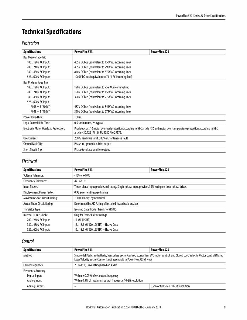
Technical Specifications
Protection
Electrical
Control
Specifications PowerFlex 523 PowerFlex 525
Bus Overvoltage Trip100...120V AC Input:200...240V AC Input:380...480V AC Input:525...600V AC Input:
405V DC bus (equivalent to 150V AC incoming line)405V DC bus (equivalent to 290V AC incoming line)810V DC bus (equivalent to 575V AC incoming line)1005V DC bus (equivalent to 711V AC incoming line)
Bus Undervoltage Trip100...120V AC Input:200...240V AC Input:380...480V AC Input:525...600V AC Input
P038 = 3 “600V”:P038 = 2 “480V”:
190V DC bus (equivalent to 75V AC incoming line)190V DC bus (equivalent to 150V AC incoming line)390V DC bus (equivalent to 275V AC incoming line)
487V DC bus (equivalent to 344V AC incoming line)390V DC bus (equivalent to 275V AC incoming line)
Power Ride-Thru: 100 ms
Logic Control Ride-Thru: 0.5 s minimum, 2 s typical
Electronic Motor Overload Protection: Provides class 10 motor overload protection according to NEC article 430 and motor over-temperature protection according to NEC article 430.126 (A) (2). UL 508C File 29572.
Overcurrent: 200% hardware limit, 300% instantaneous fault
Ground Fault Trip: Phase-to-ground on drive output
Short Circuit Trip: Phase-to-phase on drive output
Specifications PowerFlex 523 PowerFlex 525
Voltage Tolerance: -15% / +10%
Frequency Tolerance: 47...63 Hz
Input Phases: Three-phase input provides full rating. Single-phase input provides 35% rating on three-phase drives.
Displacement Power Factor: 0.98 across entire speed range
Maximum Short Circuit Rating: 100,000 Amps Symmetrical
Actual Short Circuit Rating: Determined by AIC Rating of installed fuse/circuit breaker
Transistor Type: Isolated Gate Bipolar Transistor (IGBT)
Internal DC Bus Choke200...240V AC Input:380...480V AC Input:525...600V AC Input:
Only for Frame E drive ratings11 kW (15 HP)15...18.5 kW (20...25 HP) – Heavy Duty15...18.5 kW (20...25 HP) – Heavy Duty
Specifications PowerFlex 523 PowerFlex 525
Method Sinusoidal PWM, Volts/Hertz, Sensorless Vector Control, Economizer SVC motor control, and Closed Loop Velocity Vector Control (Closed Loop Velocity Vector Control is not applicable to PowerFlex 523 drives)
Carrier Frequency 2...16 kHz, Drive rating based on 4 kHz
Frequency AccuracyDigital Input:Analog Input:
Within ±0.05% of set output frequencyWithin 0.5% of maximum output frequency, 10-Bit resolution
Analog Output: – ±2% of full scale, 10-Bit resolution
Rockwell Automation Publication 520-TD001D-EN-E - January 2014 9
PowerFlex 520-Series AC Drive Specifications
Control Inputs
Control Outputs
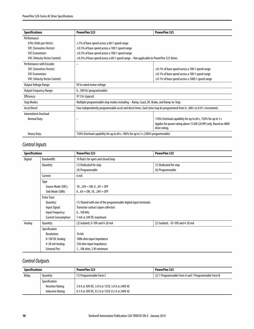
PerformanceV/Hz (Volts per Hertz):SVC (Sensorless Vector):SVC Economizer:VVC (Velocity Vector Control):
±1% of base speed across a 60:1 speed range±0.5% of base speed across a 100:1 speed range±0.5% of base speed across a 100:1 speed range±0.5% of base speed across a 60:1 speed range – Not applicable to PowerFlex 523 drives
Performance with EncoderSVC (Sensorless Vector):SVC Economizer:VVC (Velocity Vector Control):
–±0.1% of base speed across a 100:1 speed range±0.1% of base speed across a 100:1 speed range±0.1% of base speed across a 1000:1 speed range
Output Voltage Range: 0V to rated motor voltage
Output Frequency Range: 0...500 Hz (programmable)
Efficiency: 97.5% (typical)
Stop Modes: Multiple programmable stop modes including – Ramp, Coast, DC-Brake, and Ramp-to-Stop
Accel/Decel: Four independently programmable accel and decel times. Each time may be programmed from 0...600 s in 0.01 s increments.
Intermittent OverloadNormal Duty: – 110% Overload capability for up to 60 s, 150% for up to 3 s
Applies for power rating above 15 kW (20 HP) only. Based on 480V drive rating.
Heavy Duty: 150% Overload capability for up to 60 s, 180% for up to 3 s (200% programmable)
Specifications PowerFlex 523 PowerFlex 525
Digital Bandwidth: 10 Rad/s for open and closed loop
Quantity: (1) Dedicated for stop(4) Programmable
(1) Dedicated for stop(6) Programmable
Current: 6 mA
TypeSource Mode (SRC):Sink Mode (SNK):
18...24V = ON, 0...6V = OFF0...6V = ON, 18...24V = OFF
Pulse TrainQuantity:Input Signal:Input Frequency:Current Consumption:
(1) Shared with one of the programmable digital input terminals.Transistor contact (open collector)0...100 kHz7 mA @ 24V DC maximum
Analog Quantity: (2) Isolated, 0-10V and 4-20 mA (2) Isolated, -10-10V and 4-20 mA
SpecificationResolution:0-10V DC Analog:4-20 mA Analog:External Pot:
10-bit100k ohm input impedance250 ohm input impedance1...10k ohm, 2 W minimum
Specifications PowerFlex 523 PowerFlex 525
Relay Quantity: (1) Programmable Form C (2) 1 Programmable Form A and 1 Programmable Form B
SpecificationResistive Rating:Inductive Rating:
3.0 A @ 30V DC, 3.0 A @ 125V, 3.0 A @ 240V AC0.5 A @ 30V DC, 0.5 A @ 125V, 0.5 A @ 240V AC
Specifications PowerFlex 523 PowerFlex 525
10 Rockwell Automation Publication 520-TD001D-EN-E - January 2014
PowerFlex 520-Series AC Drive Specifications
Encoder
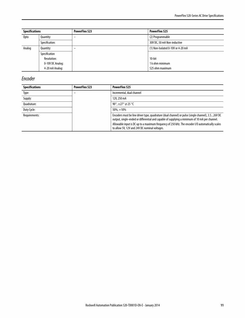
Opto Quantity: – (2) Programmable
Specification: 30V DC, 50 mA Non-inductive
Analog Quantity: – (1) Non-Isolated 0-10V or 4-20 mA
SpecificationResolution:0-10V DC Analog:4-20 mA Analog:
10-bit1 k ohm minimum525 ohm maximum
Specifications PowerFlex 523 PowerFlex 525
Type: – Incremental, dual channel
Supply: 12V, 250 mA
Quadrature: 90°, ±27° @ 25 °C
Duty Cycle: 50%, +10%
Requirements: Encoders must be line driver type, quadrature (dual channel) or pulse (single channel), 3.5...26V DC output, single-ended or differential and capable of supplying a minimum of 10 mA per channel. Allowable input is DC up to a maximum frequency of 250 kHz. The encoder I/O automatically scales to allow 5V, 12V and 24V DC nominal voltages.
Specifications PowerFlex 523 PowerFlex 525
Rockwell Automation Publication 520-TD001D-EN-E - January 2014 11
PowerFlex 520-Series AC Drive Specifications
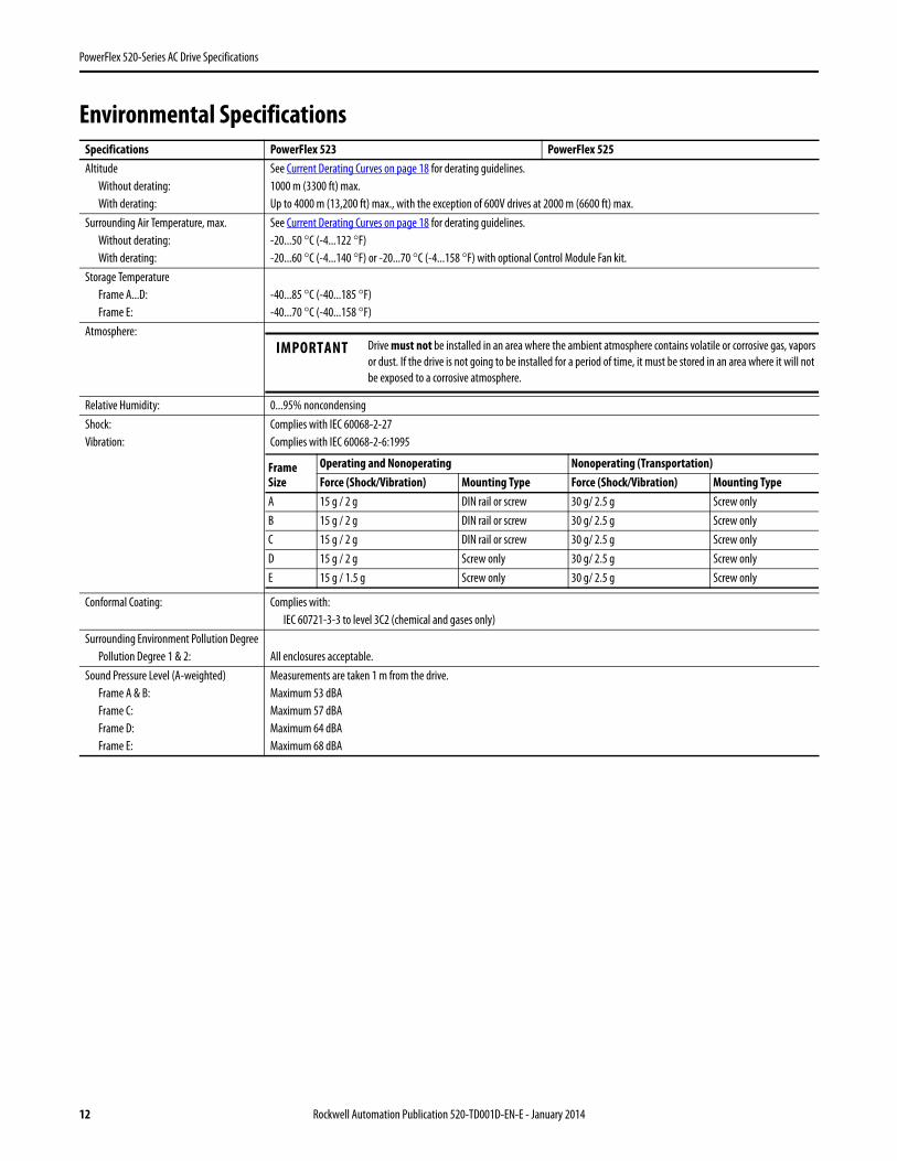
Environmental SpecificationsSpecifications PowerFlex 523 PowerFlex 525Altitude
Without derating:With derating:
See Current Derating Curves on page 18 for derating guidelines.1000 m (3300 ft) max.Up to 4000 m (13,200 ft) max., with the exception of 600V drives at 2000 m (6600 ft) max.
Surrounding Air Temperature, max.Without derating:With derating:
See Current Derating Curves on page 18 for derating guidelines.-20...50 °C (-4...122 °F)-20...60 °C (-4...140 °F) or -20...70 °C (-4...158 °F) with optional Control Module Fan kit.
Storage TemperatureFrame A...D:Frame E:
-40...85 °C (-40...185 °F)-40...70 °C (-40...158 °F)
Atmosphere:
Relative Humidity: 0...95% noncondensingShock:Vibration:
Complies with IEC 60068-2-27Complies with IEC 60068-2-6:1995
Conformal Coating: Complies with:IEC 60721-3-3 to level 3C2 (chemical and gases only)
Surrounding Environment Pollution DegreePollution Degree 1 & 2: All enclosures acceptable.
Sound Pressure Level (A-weighted)Frame A & B:Frame C:Frame D:Frame E:
Measurements are taken 1 m from the drive.Maximum 53 dBAMaximum 57 dBAMaximum 64 dBAMaximum 68 dBA
IMPORTANT Drive must not be installed in an area where the ambient atmosphere contains volatile or corrosive gas, vapors or dust. If the drive is not going to be installed for a period of time, it must be stored in an area where it will not be exposed to a corrosive atmosphere.
FrameSize
Operating and Nonoperating Nonoperating (Transportation)Force (Shock/Vibration) Mounting Type Force (Shock/Vibration) Mounting Type
A 15 g / 2 g DIN rail or screw 30 g/ 2.5 g Screw onlyB 15 g / 2 g DIN rail or screw 30 g/ 2.5 g Screw onlyC 15 g / 2 g DIN rail or screw 30 g/ 2.5 g Screw onlyD 15 g / 2 g Screw only 30 g/ 2.5 g Screw onlyE 15 g / 1.5 g Screw only 30 g/ 2.5 g Screw only
12 Rockwell Automation Publication 520-TD001D-EN-E - January 2014
PowerFlex 520-Series AC Drive Specifications
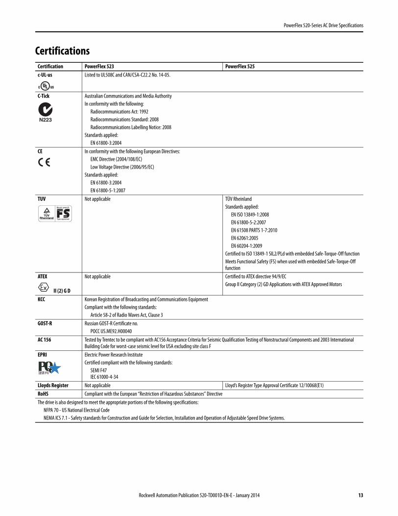
CertificationsCertification PowerFlex 523 PowerFlex 525c-UL-us Listed to UL508C and CAN/CSA-C22.2 No. 14-05.
C-Tick Australian Communications and Media AuthorityIn conformity with the following:
Radiocommunications Act: 1992Radiocommunications Standard: 2008Radiocommunications Labelling Notice: 2008
Standards applied:EN 61800-3:2004
CE In conformity with the following European Directives:EMC Directive (2004/108/EC)Low Voltage Directive (2006/95/EC)
Standards applied:EN 61800-3:2004EN 61800-5-1:2007
TUV Not applicable TÜV RheinlandStandards applied:
EN ISO 13849-1:2008EN 61800-5-2:2007EN 61508 PARTS 1-7:2010EN 62061:2005EN 60204-1:2009
Certified to ISO 13849-1 SIL2/PLd with embedded Safe-Torque-Off functionMeets Functional Safety (FS) when used with embedded Safe-Torque-Off function
ATEX
II (2) G D
Not applicable Certified to ATEX directive 94/9/ECGroup II Category (2) GD Applications with ATEX Approved Motors
KCC Korean Registration of Broadcasting and Communications EquipmentCompliant with the following standards:
Article 58-2 of Radio Waves Act, Clause 3GOST-R Russian GOST-R Certificate no.
POCC US.ME92.H00040AC 156 Tested by Trentec to be compliant with AC156 Acceptance Criteria for Seismic Qualification Testing of Nonstructural Components and 2003 International
Building Code for worst-case seismic level for USA excluding site class FEPRI Electric Power Research Institute
Certified compliant with the following standards:SEMI F47IEC 61000-4-34
Lloyds Register Not applicable Lloyd’s Register Type Approval Certificate 12/10068(E1)RoHS Compliant with the European “Restriction of Hazardous Substances” DirectiveThe drive is also designed to meet the appropriate portions of the following specifications:
NFPA 70 - US National Electrical CodeNEMA ICS 7.1 - Safety standards for Construction and Guide for Selection, Installation and Operation of Adjustable Speed Drive Systems.
N223
TUV Rheinland
..Functional
Safety
Bauart geprüft
Type approved
Rockwell Automation Publication 520-TD001D-EN-E - January 2014 13
PowerFlex 520-Series AC Drive Specifications
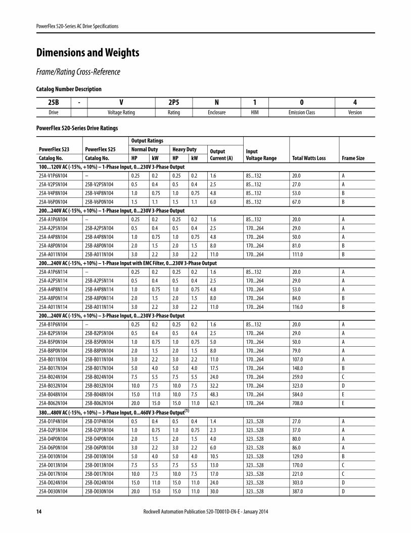
Dimensions and Weights
Frame/Rating Cross-Reference
Catalog Number Description
PowerFlex 520-Series Drive Ratings
25B - V 2P5 N 1 0 4Drive Voltage Rating Rating Enclosure HIM Emission Class Version
PowerFlex 523 PowerFlex 525Output Ratings
InputVoltage Range Total Watts Loss Frame Size
Normal Duty Heavy Duty OutputCurrent (A)Catalog No. Catalog No. HP kW HP kW
100...120V AC (-15%, +10%) – 1-Phase Input, 0...230V 3-Phase Output 25A-V1P6N104 – 0.25 0.2 0.25 0.2 1.6 85...132 20.0 A25A-V2P5N104 25B-V2P5N104 0.5 0.4 0.5 0.4 2.5 85...132 27.0 A25A-V4P8N104 25B-V4P8N104 1.0 0.75 1.0 0.75 4.8 85...132 53.0 B25A-V6P0N104 25B-V6P0N104 1.5 1.1 1.5 1.1 6.0 85...132 67.0 B200...240V AC (-15%, +10%) – 1-Phase Input, 0...230V 3-Phase Output25A-A1P6N104 – 0.25 0.2 0.25 0.2 1.6 85...132 20.0 A25A-A2P5N104 25B-A2P5N104 0.5 0.4 0.5 0.4 2.5 170...264 29.0 A25A-A4P8N104 25B-A4P8N104 1.0 0.75 1.0 0.75 4.8 170...264 50.0 A25A-A8P0N104 25B-A8P0N104 2.0 1.5 2.0 1.5 8.0 170...264 81.0 B25A-A011N104 25B-A011N104 3.0 2.2 3.0 2.2 11.0 170...264 111.0 B200...240V AC (-15%, +10%) – 1-Phase Input with EMC Filter, 0...230V 3-Phase Output25A-A1P6N114 – 0.25 0.2 0.25 0.2 1.6 85...132 20.0 A25A-A2P5N114 25B-A2P5N114 0.5 0.4 0.5 0.4 2.5 170...264 29.0 A25A-A4P8N114 25B-A4P8N114 1.0 0.75 1.0 0.75 4.8 170...264 53.0 A25A-A8P0N114 25B-A8P0N114 2.0 1.5 2.0 1.5 8.0 170...264 84.0 B25A-A011N114 25B-A011N114 3.0 2.2 3.0 2.2 11.0 170...264 116.0 B200...240V AC (-15%, +10%) – 3-Phase Input, 0...230V 3-Phase Output25A-B1P6N104 – 0.25 0.2 0.25 0.2 1.6 85...132 20.0 A25A-B2P5N104 25B-B2P5N104 0.5 0.4 0.5 0.4 2.5 170...264 29.0 A25A-B5P0N104 25B-B5P0N104 1.0 0.75 1.0 0.75 5.0 170...264 50.0 A25A-B8P0N104 25B-B8P0N104 2.0 1.5 2.0 1.5 8.0 170...264 79.0 A25A-B011N104 25B-B011N104 3.0 2.2 3.0 2.2 11.0 170...264 107.0 A25A-B017N104 25B-B017N104 5.0 4.0 5.0 4.0 17.5 170...264 148.0 B25A-B024N104 25B-B024N104 7.5 5.5 7.5 5.5 24.0 170...264 259.0 C25A-B032N104 25B-B032N104 10.0 7.5 10.0 7.5 32.2 170...264 323.0 D25A-B048N104 25B-B048N104 15.0 11.0 10.0 7.5 48.3 170...264 584.0 E25A-B062N104 25B-B062N104 20.0 15.0 15.0 11.0 62.1 170...264 708.0 E
380...480V AC (-15%, +10%) – 3-Phase Input, 0...460V 3-Phase Output(1)
25A-D1P4N104 25B-D1P4N104 0.5 0.4 0.5 0.4 1.4 323...528 27.0 A25A-D2P3N104 25B-D2P3N104 1.0 0.75 1.0 0.75 2.3 323...528 37.0 A25A-D4P0N104 25B-D4P0N104 2.0 1.5 2.0 1.5 4.0 323...528 80.0 A25A-D6P0N104 25B-D6P0N104 3.0 2.2 3.0 2.2 6.0 323...528 86.0 A25A-D010N104 25B-D010N104 5.0 4.0 5.0 4.0 10.5 323...528 129.0 B25A-D013N104 25B-D013N104 7.5 5.5 7.5 5.5 13.0 323...528 170.0 C25A-D017N104 25B-D017N104 10.0 7.5 10.0 7.5 17.0 323...528 221.0 C25A-D024N104 25B-D024N104 15.0 11.0 15.0 11.0 24.0 323...528 303.0 D25A-D030N104 25B-D030N104 20.0 15.0 15.0 11.0 30.0 323...528 387.0 D
14 Rockwell Automation Publication 520-TD001D-EN-E - January 2014
PowerFlex 520-Series AC Drive Specifications
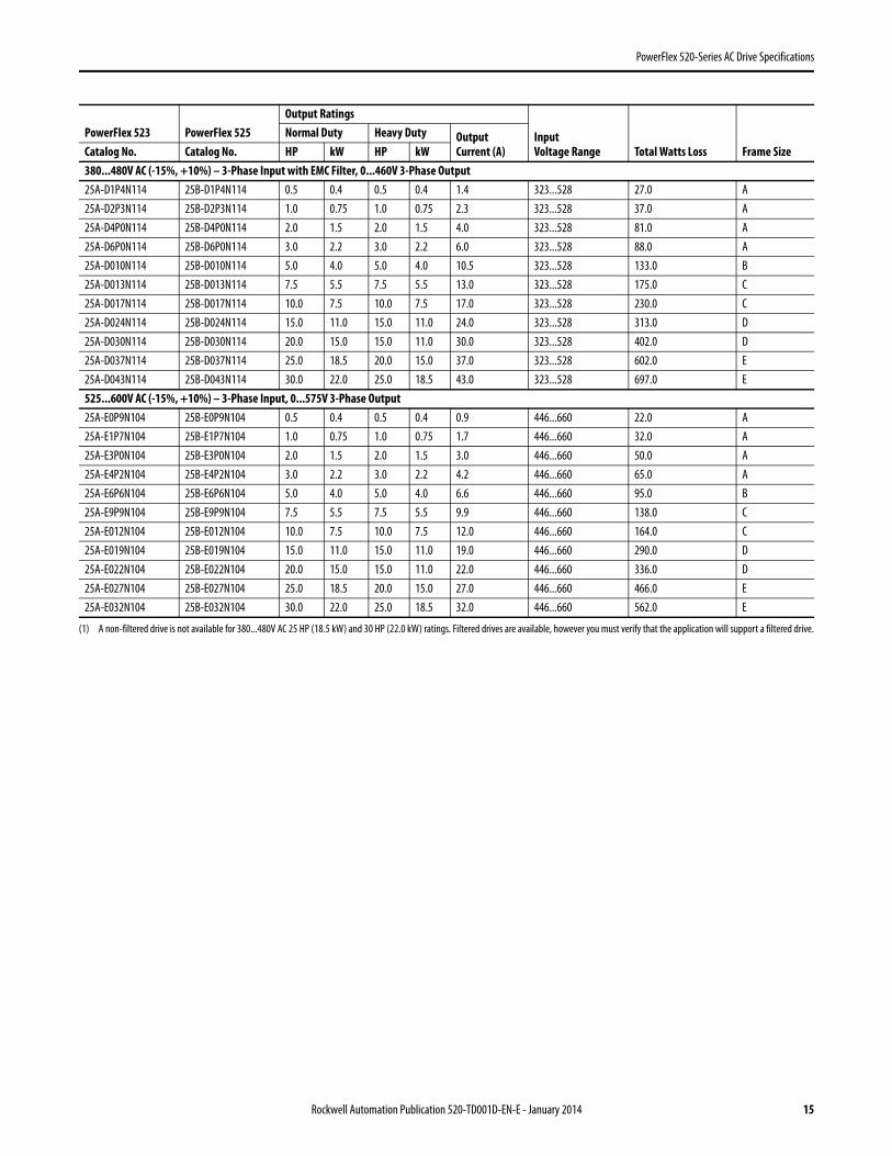
(1) A non-filtered drive is not available for 380...480V AC 25 HP (18.5 kW) and 30 HP (22.0 kW) ratings. Filtered drives are available, however you must verify that the application will support a filtered drive.
380...480V AC (-15%, +10%) – 3-Phase Input with EMC Filter, 0...460V 3-Phase Output25A-D1P4N114 25B-D1P4N114 0.5 0.4 0.5 0.4 1.4 323...528 27.0 A25A-D2P3N114 25B-D2P3N114 1.0 0.75 1.0 0.75 2.3 323...528 37.0 A25A-D4P0N114 25B-D4P0N114 2.0 1.5 2.0 1.5 4.0 323...528 81.0 A25A-D6P0N114 25B-D6P0N114 3.0 2.2 3.0 2.2 6.0 323...528 88.0 A25A-D010N114 25B-D010N114 5.0 4.0 5.0 4.0 10.5 323...528 133.0 B25A-D013N114 25B-D013N114 7.5 5.5 7.5 5.5 13.0 323...528 175.0 C25A-D017N114 25B-D017N114 10.0 7.5 10.0 7.5 17.0 323...528 230.0 C25A-D024N114 25B-D024N114 15.0 11.0 15.0 11.0 24.0 323...528 313.0 D25A-D030N114 25B-D030N114 20.0 15.0 15.0 11.0 30.0 323...528 402.0 D25A-D037N114 25B-D037N114 25.0 18.5 20.0 15.0 37.0 323...528 602.0 E25A-D043N114 25B-D043N114 30.0 22.0 25.0 18.5 43.0 323...528 697.0 E525...600V AC (-15%, +10%) – 3-Phase Input, 0...575V 3-Phase Output25A-E0P9N104 25B-E0P9N104 0.5 0.4 0.5 0.4 0.9 446...660 22.0 A25A-E1P7N104 25B-E1P7N104 1.0 0.75 1.0 0.75 1.7 446...660 32.0 A25A-E3P0N104 25B-E3P0N104 2.0 1.5 2.0 1.5 3.0 446...660 50.0 A25A-E4P2N104 25B-E4P2N104 3.0 2.2 3.0 2.2 4.2 446...660 65.0 A25A-E6P6N104 25B-E6P6N104 5.0 4.0 5.0 4.0 6.6 446...660 95.0 B25A-E9P9N104 25B-E9P9N104 7.5 5.5 7.5 5.5 9.9 446...660 138.0 C25A-E012N104 25B-E012N104 10.0 7.5 10.0 7.5 12.0 446...660 164.0 C25A-E019N104 25B-E019N104 15.0 11.0 15.0 11.0 19.0 446...660 290.0 D25A-E022N104 25B-E022N104 20.0 15.0 15.0 11.0 22.0 446...660 336.0 D25A-E027N104 25B-E027N104 25.0 18.5 20.0 15.0 27.0 446...660 466.0 E25A-E032N104 25B-E032N104 30.0 22.0 25.0 18.5 32.0 446...660 562.0 E
PowerFlex 523 PowerFlex 525Output Ratings
InputVoltage Range Total Watts Loss Frame Size
Normal Duty Heavy Duty OutputCurrent (A)Catalog No. Catalog No. HP kW HP kW
Rockwell Automation Publication 520-TD001D-EN-E - January 2014 15
PowerFlex 520-Series AC Drive Specifications
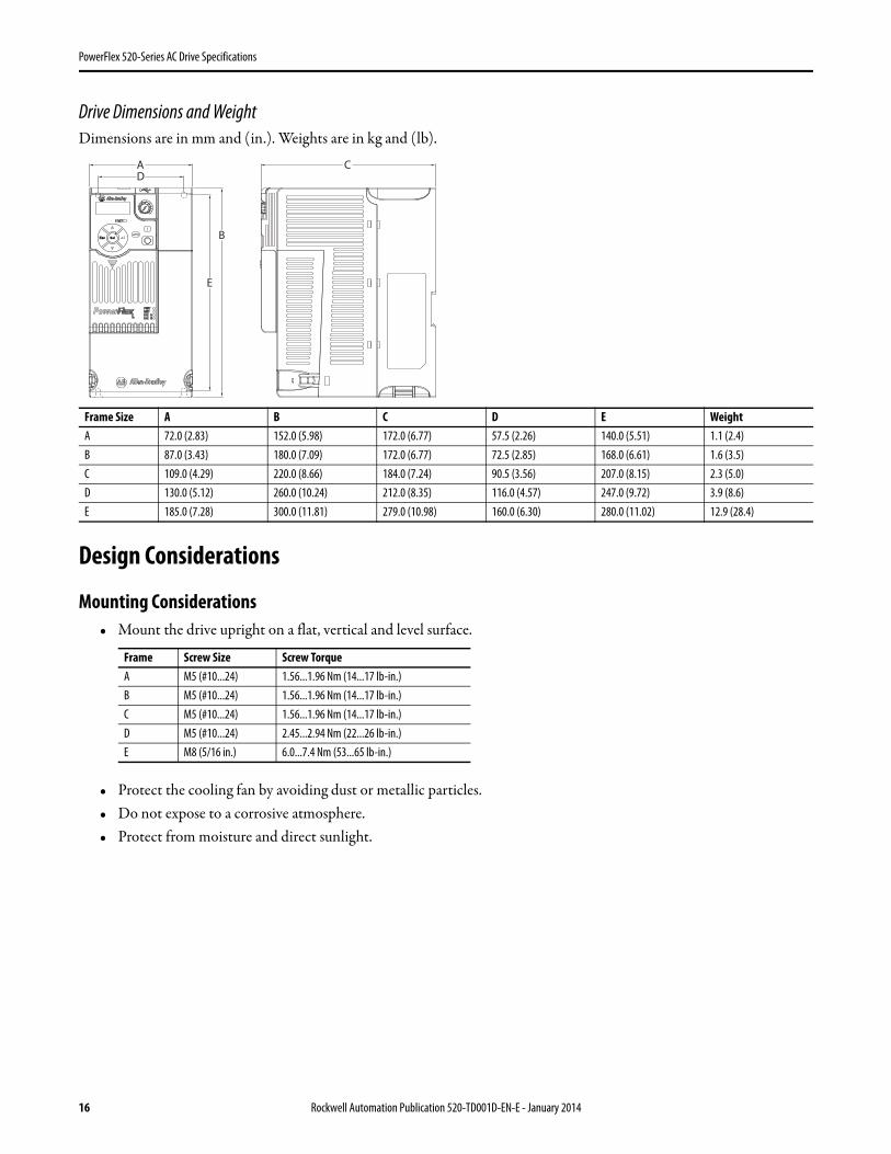
Drive Dimensions and WeightDimensions are in mm and (in.). Weights are in kg and (lb).
Design Considerations
Mounting Considerations• Mount the drive upright on a flat, vertical and level surface.
• Protect the cooling fan by avoiding dust or metallic particles.• Do not expose to a corrosive atmosphere.• Protect from moisture and direct sunlight.
Frame Size A B C D E WeightA 72.0 (2.83) 152.0 (5.98) 172.0 (6.77) 57.5 (2.26) 140.0 (5.51) 1.1 (2.4)B 87.0 (3.43) 180.0 (7.09) 172.0 (6.77) 72.5 (2.85) 168.0 (6.61) 1.6 (3.5)C 109.0 (4.29) 220.0 (8.66) 184.0 (7.24) 90.5 (3.56) 207.0 (8.15) 2.3 (5.0)D 130.0 (5.12) 260.0 (10.24) 212.0 (8.35) 116.0 (4.57) 247.0 (9.72) 3.9 (8.6)E 185.0 (7.28) 300.0 (11.81) 279.0 (10.98) 160.0 (6.30) 280.0 (11.02) 12.9 (28.4)
Frame Screw Size Screw TorqueA M5 (#10...24) 1.56...1.96 Nm (14...17 lb-in.)B M5 (#10...24) 1.56...1.96 Nm (14...17 lb-in.)C M5 (#10...24) 1.56...1.96 Nm (14...17 lb-in.)D M5 (#10...24) 2.45...2.94 Nm (22...26 lb-in.)E M8 (5/16 in.) 6.0...7.4 Nm (53...65 lb-in.)
Esc Sel
A C
B
E
D
16 Rockwell Automation Publication 520-TD001D-EN-E - January 2014
PowerFlex 520-Series AC Drive Specifications
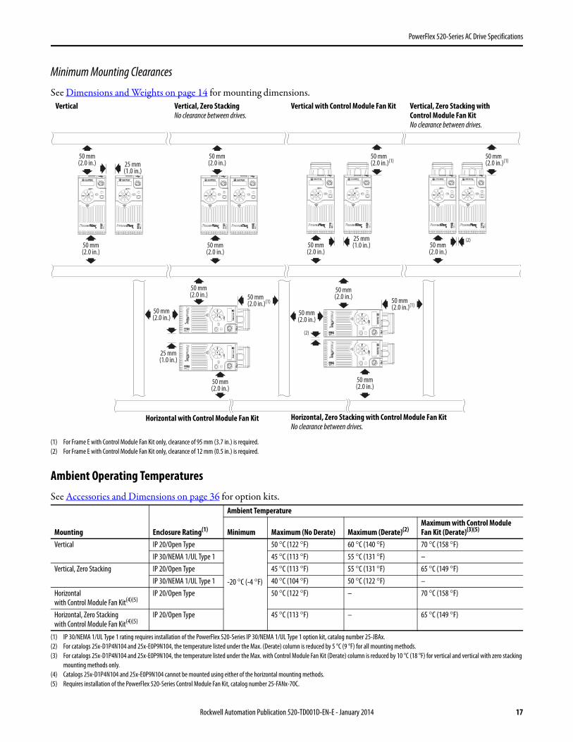
Minimum Mounting Clearances
See Dimensions and Weights on page 14 for mounting dimensions.
(1) For Frame E with Control Module Fan Kit only, clearance of 95 mm (3.7 in.) is required.(2) For Frame E with Control Module Fan Kit only, clearance of 12 mm (0.5 in.) is required.
Ambient Operating TemperaturesSee Accessories and Dimensions on page 36 for option kits.
(1) IP 30/NEMA 1/UL Type 1 rating requires installation of the PowerFlex 520-Series IP 30/NEMA 1/UL Type 1 option kit, catalog number 25-JBAx.(2) For catalogs 25x-D1P4N104 and 25x-E0P9N104, the temperature listed under the Max. (Derate) column is reduced by 5 °C (9 °F) for all mounting methods.(3) For catalogs 25x-D1P4N104 and 25x-E0P9N104, the temperature listed under the Max. with Control Module Fan Kit (Derate) column is reduced by 10 °C (18 °F) for vertical and vertical with zero stacking
mounting methods only.(4) Catalogs 25x-D1P4N104 and 25x-E0P9N104 cannot be mounted using either of the horizontal mounting methods.(5) Requires installation of the PowerFlex 520-Series Control Module Fan Kit, catalog number 25-FANx-70C.
Mounting Enclosure Rating(1)
Ambient Temperature
Minimum Maximum (No Derate) Maximum (Derate)(2)Maximum with Control ModuleFan Kit (Derate)(3)(5)
Vertical IP 20/Open Type
-20 °C (-4 °F)
50 °C (122 °F) 60 °C (140 °F) 70 °C (158 °F)IP 30/NEMA 1/UL Type 1 45 °C (113 °F) 55 °C (131 °F) –
Vertical, Zero Stacking IP 20/Open Type 45 °C (113 °F) 55 °C (131 °F) 65 °C (149 °F)IP 30/NEMA 1/UL Type 1 40 °C (104 °F) 50 °C (122 °F) –
Horizontalwith Control Module Fan Kit(4)(5)
IP 20/Open Type 50 °C (122 °F) – 70 °C (158 °F)
Horizontal, Zero Stackingwith Control Module Fan Kit(4)(5)
IP 20/Open Type 45 °C (113 °F) – 65 °C (149 °F)
25 mm(1.0 in.)
25 mm(1.0 in.)
(2)
(2)
25 mm(1.0 in.)
50 mm(2.0 in.)
50 mm(2.0 in.)(1)
50 mm(2.0 in.)(1)
50 mm(2.0 in.)(1)
50 mm(2.0 in.)
50 mm(2.0 in.)
50 mm(2.0 in.)
Esc Sel Esc SelEsc Sel Esc Sel
50 mm(2.0 in.)
50 mm(2.0 in.)
50 mm(2.0 in.)
50 mm(2.0 in.)
Esc
Se
lE
s cS
el
50 mm(2.0 in.)
50 mm(2.0 in.)
50 mm(2.0 in.)
50 mm(2.0 in.)
50 mm(2.0 in.)(1)
Esc
Se
lE
scS
el
Esc Sel Esc Sel Esc SelEsc Sel
Vertical, Zero StackingNo clearance between drives.
Horizontal, Zero Stacking with Control Module Fan KitNo clearance between drives.
Vertical Vertical, Zero Stacking withControl Module Fan KitNo clearance between drives.
Vertical with Control Module Fan Kit
Horizontal with Control Module Fan Kit
Rockwell Automation Publication 520-TD001D-EN-E - January 2014 17
PowerFlex 520-Series AC Drive Specifications
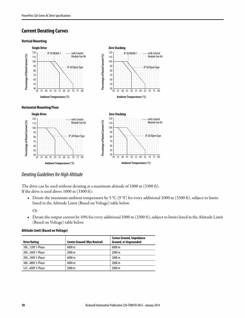
Current Derating Curves
Vertical Mounting
Horizontal Mounting/Floor
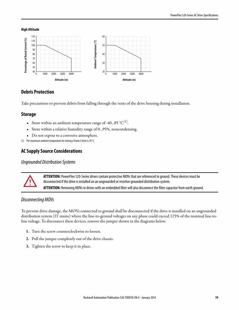
Derating Guidelines for High Altitude
The drive can be used without derating at a maximum altitude of 1000 m (3300 ft).If the drive is used above 1000 m (3300 ft):
• Derate the maximum ambient temperature by 5 °C (9 °F) for every additional 1000 m (3300 ft), subject to limits listed in the Altitude Limit (Based on Voltage) table below.
Or• Derate the output current by 10% for every additional 1000 m (3300 ft), subject to limits listed in the Altitude Limit
(Based on Voltage) table below.
Altitude Limit (Based on Voltage)
Drive Rating Center Ground (Wye Neutral)Corner Ground, Impedance Ground, or Ungrounded
100...120V 1-Phase 6000 m 6000 m200...240V 1-Phase 2000 m 2000 m200...240V 3-Phase 6000 m 2000 m380...480V 3-Phase 4000 m 2000 m525...600V 3-Phase 2000 m 2000 m
Ambient Temperature (°C)
40
10090
110120
80706050
45403530 60 65 70 75 805550
Perc
enta
ge of
Rat
ed Cu
rrent
(%) IP 30/NEMA 1 with Control
Module Fan Kit
IP 20/Open Type
Ambient Temperature (°C)
40
10090
110120
80706050
45403530 60 65 70 75 805550
Perc
enta
ge of
Rat
ed Cu
rrent
(%) IP 30/NEMA 1 with Control
Module Fan Kit
IP 20/Open Type
Single Drive Zero Stacking
Ambient Temperature (°C)
40
10090
120110
80706050
30 35 70 75 8060 6550 5540 45
Perc
enta
ge of
Rat
ed Cu
rrent
(%) with Control
Module Fan Kit
IP 20/Open Type
Ambient Temperature (°C)
40
10090
120110
80706050
30 35 70 75 8060 6550 5540 45
Perc
enta
ge of
Rat
ed Cu
rrent
(%) with Control
Module Fan Kit
IP 20/Open Type
Single Drive Zero Stacking
18 Rockwell Automation Publication 520-TD001D-EN-E - January 2014
PowerFlex 520-Series AC Drive Specifications
High Altitude
Debris Protection
Take precautions to prevent debris from falling through the vents of the drive housing during installation.
Storage• Store within an ambient temperature range of -40...85 °C(1).• Store within a relative humidity range of 0...95%, noncondensing.• Do not expose to a corrosive atmosphere.
(1) The maximum ambient temperature for storing a Frame E drive is 70 °C.
AC Supply Source Considerations
Ungrounded Distribution Systems
Disconnecting MOVs
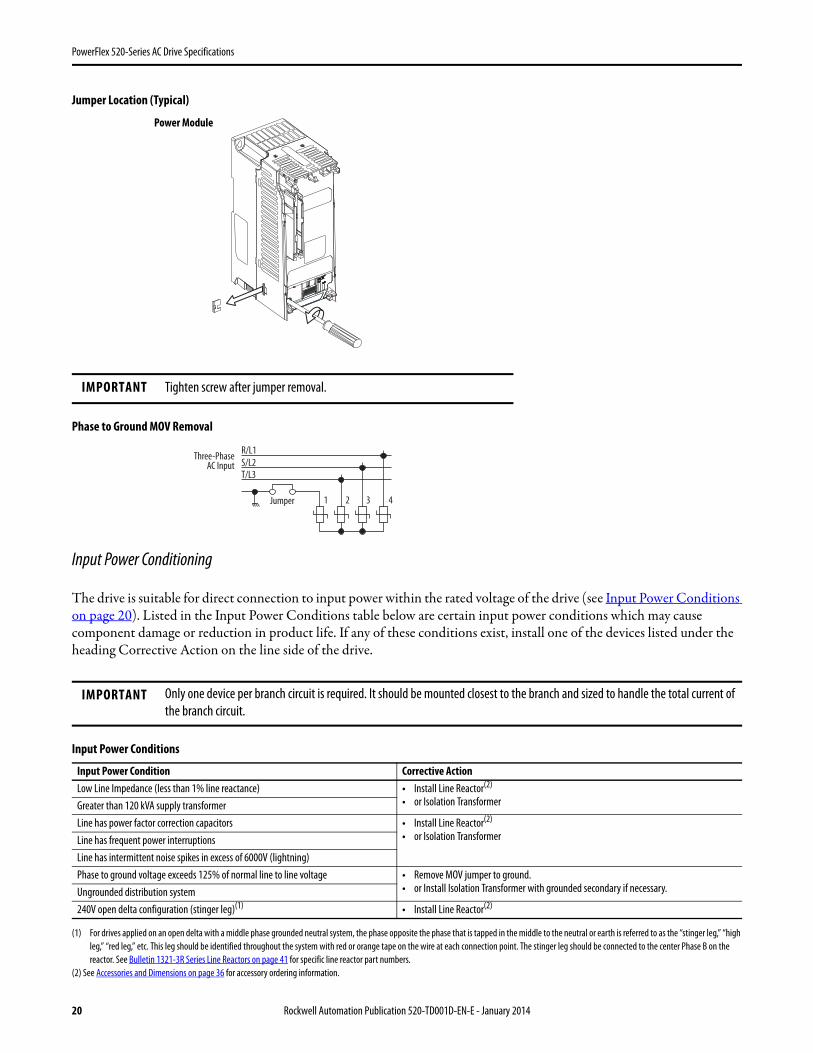
To prevent drive damage, the MOVs connected to ground shall be disconnected if the drive is installed on an ungrounded distribution system (IT mains) where the line-to-ground voltages on any phase could exceed 125% of the nominal line-to-line voltage. To disconnect these devices, remove the jumper shown in the diagrams below.
1. Turn the screw counterclockwise to loosen.
2. Pull the jumper completely out of the drive chassis.
3. Tighten the screw to keep it in place.
ATTENTION: PowerFlex 520-Series drives contain protective MOVs that are referenced to ground. These devices must be disconnected if the drive is installed on an ungrounded or resistive grounded distribution system.ATTENTION: Removing MOVs in drives with an embedded filter will also disconnect the filter capacitor from earth ground.
Altitude (m)
Perc
enta
ge of
Rat
ed Cu
rrent
(%)
40
90100110120
80706050
0 4000300020001000
Altitude (m)
Ambi
ent T
empe
ratu
re (°
C)
20
50
60
40
30
0 4000300020001000
Rockwell Automation Publication 520-TD001D-EN-E - January 2014 19
PowerFlex 520-Series AC Drive Specifications
Jumper Location (Typical)
Phase to Ground MOV Removal
Input Power Conditioning
The drive is suitable for direct connection to input power within the rated voltage of the drive (see Input Power Conditions on page 20). Listed in the Input Power Conditions table below are certain input power conditions which may cause component damage or reduction in product life. If any of these conditions exist, install one of the devices listed under the heading Corrective Action on the line side of the drive.
Input Power Conditions
(1) For drives applied on an open delta with a middle phase grounded neutral system, the phase opposite the phase that is tapped in the middle to the neutral or earth is referred to as the “stinger leg,” “high leg,” “red leg,” etc. This leg should be identified throughout the system with red or orange tape on the wire at each connection point. The stinger leg should be connected to the center Phase B on the reactor. See Bulletin 1321-3R Series Line Reactors on page 41 for specific line reactor part numbers.
(2) See Accessories and Dimensions on page 36 for accessory ordering information.
IMPORTANT Tighten screw after jumper removal.
IMPORTANT Only one device per branch circuit is required. It should be mounted closest to the branch and sized to handle the total current of the branch circuit.
Input Power Condition Corrective ActionLow Line Impedance (less than 1% line reactance) • Install Line Reactor(2)
• or Isolation TransformerGreater than 120 kVA supply transformerLine has power factor correction capacitors • Install Line Reactor(2)
• or Isolation TransformerLine has frequent power interruptionsLine has intermittent noise spikes in excess of 6000V (lightning)Phase to ground voltage exceeds 125% of normal line to line voltage • Remove MOV jumper to ground.
• or Install Isolation Transformer with grounded secondary if necessary.Ungrounded distribution system240V open delta configuration (stinger leg)(1) • Install Line Reactor(2)
Power Module
R/L1S/L2T/L3
1 2 3 4
Three-PhaseAC Input
Jumper
20 Rockwell Automation Publication 520-TD001D-EN-E - January 2014
PowerFlex 520-Series AC Drive Specifications
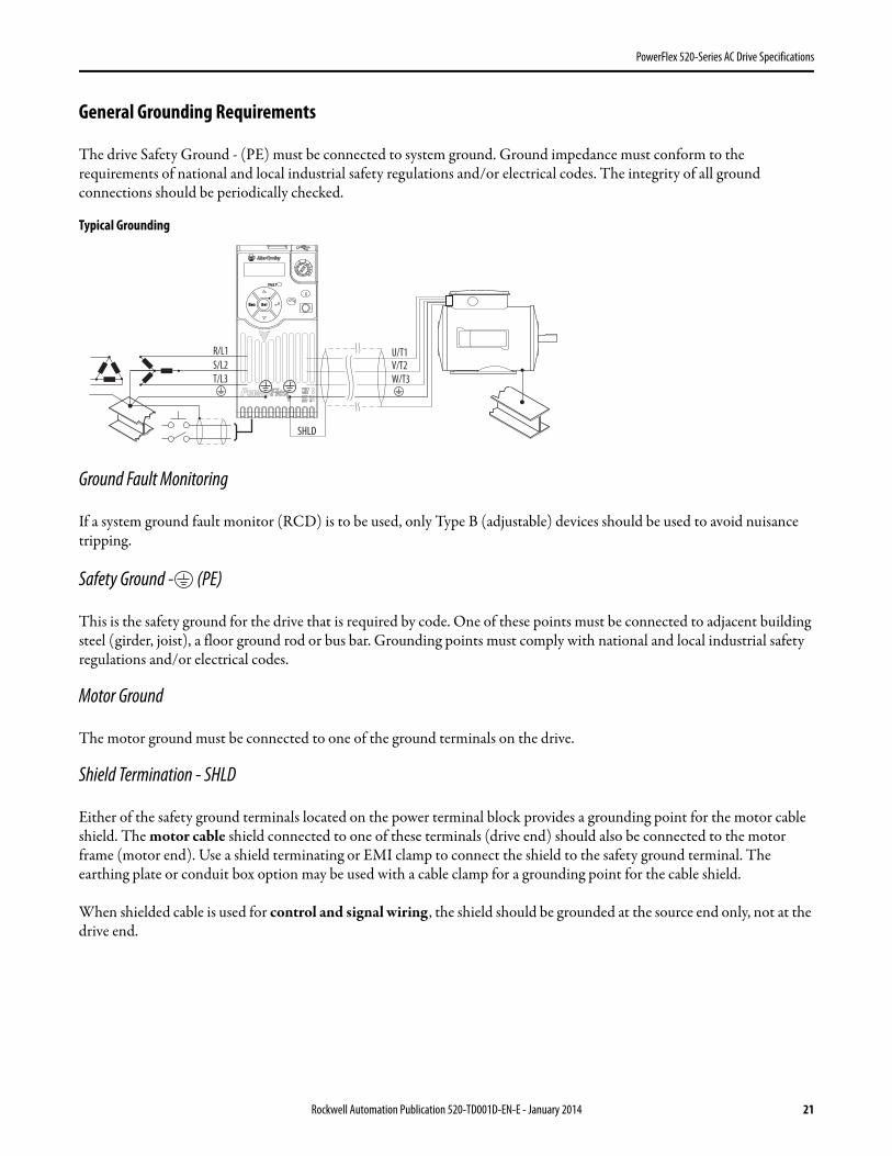
General Grounding Requirements
The drive Safety Ground - (PE) must be connected to system ground. Ground impedance must conform to the requirements of national and local industrial safety regulations and/or electrical codes. The integrity of all ground connections should be periodically checked.
Typical Grounding
Ground Fault Monitoring
If a system ground fault monitor (RCD) is to be used, only Type B (adjustable) devices should be used to avoid nuisance tripping.
Safety Ground - (PE)
This is the safety ground for the drive that is required by code. One of these points must be connected to adjacent building steel (girder, joist), a floor ground rod or bus bar. Grounding points must comply with national and local industrial safety regulations and/or electrical codes.
Motor Ground
The motor ground must be connected to one of the ground terminals on the drive.
Shield Termination - SHLD
Either of the safety ground terminals located on the power terminal block provides a grounding point for the motor cable shield. The motor cable shield connected to one of these terminals (drive end) should also be connected to the motor frame (motor end). Use a shield terminating or EMI clamp to connect the shield to the safety ground terminal. The earthing plate or conduit box option may be used with a cable clamp for a grounding point for the cable shield.
When shielded cable is used for control and signal wiring , the shield should be grounded at the source end only, not at the drive end.
SHLD
U/T1V/T2W/T3
R/L1S/L2T/L3
Esc Sel
Rockwell Automation Publication 520-TD001D-EN-E - January 2014 21
PowerFlex 520-Series AC Drive Specifications
RFI Filter Grounding
Using a drive with filter may result in relatively high ground leakage currents. Therefore, the filter must only be used in installations with grounded AC supply systems and be permanently installed and solidly grounded (bonded) to the building power distribution ground. Ensure that the incoming supply neutral is solidly connected (bonded) to the same building power distribution ground. Grounding must not rely on flexible cables and should not include any form of plug or socket that would permit inadvertent disconnection. Some local codes may require redundant ground connections. The integrity of all connections should be periodically checked.
Power Wiring
Motor Cable Types Acceptable for 100...600 Volt Installations
A variety of cable types are acceptable for drive installations. For many installations, unshielded cable is adequate, provided it can be separated from sensitive circuits. As an approximate guide, allow a spacing of 0.3 m (1 ft) for every 10 m (32.8 ft) of length. In all cases, long parallel runs must be avoided. Do not use cable with an insulation thickness less than 15 mils (0.4 mm/0.015 in.). Do not route more than three sets of motor leads in a single conduit to minimize “cross talk”. If more than three drive/motor connections per conduit are required, shielded cable must be used.UL installations above 50 °C ambient must use 600V, 90 °C wire.UL installations in 50 °C ambient must use 600V, 75 °C or 90 °C wire.UL installations in 40 °C ambient should use 600V, 75 °C or 90 °C wire.
Use copper wire only. Wire gauge requirements and recommendations are based on 75 °C. Do not reduce wire gauge when using higher temperature wire.
Unshielded
THHN, THWN or similar wire is acceptable for drive installation in dry environments provided adequate free air space and/or conduit fill rates limits are provided. Any wire chosen must have a minimum insulation thickness of 15 mils and should not have large variations in insulation concentricity.
ATTENTION: National Codes and standards (NEC, VDE, BSI, etc.) and local codes outline provisions for safely installing electrical equipment. Installation must comply with specifications regarding wire types, conductor sizes, branch circuit protection and disconnect devices. Failure to do so may result in personal injury and/or equipment damage.ATTENTION: To avoid a possible shock hazard caused by induced voltages, unused wires in the conduit must be grounded at both ends. For the same reason, if a drive sharing a conduit is being serviced or installed, all drives using this conduit should be disabled. This will help minimize the possible shock hazard from “cross coupled” power leads.
ATTENTION: Do not use THHN or similarly coated wire in wet areas.
22 Rockwell Automation Publication 520-TD001D-EN-E - January 2014
PowerFlex 520-Series AC Drive Specifications
Shielded/Armored Cable
Shielded cable contains all of the general benefits of multi-conductor cable with the added benefit of a copper braided shield that can contain much of the noise generated by a typical AC Drive. Strong consideration for shielded cable should be given in installations with sensitive equipment such as weigh scales, capacitive proximity switches and other devices that may be affected by electrical noise in the distribution system. Applications with large numbers of drives in a similar location, imposed EMC regulations or a high degree of communications / networking are also good candidates for shielded cable.
Shielded cable may also help reduce shaft voltage and induced bearing currents for some applications. In addition, the increased impedance of shielded cable may help extend the distance that the motor can be located from the drive without the addition of motor protective devices such as terminator networks. Refer to Reflected Wave in “Wiring and Grounding Guide, (PWM) AC Drives,” publication DRIVES-IN001.
Consideration should be given to all of the general specifications dictated by the environment of the installation, including temperature, flexibility, moisture characteristics and chemical resistance. In addition, a braided shield should be included and be specified by the cable manufacturer as having coverage of at least 75%. An additional foil shield can greatly improve noise containment.
A good example of recommended cable is Belden® 295xx (xx determines gauge). This cable has four (4) XLPE insulated conductors with a 100% coverage foil and an 85% coverage copper braided shield (with drain wire) surrounded by a PVC jacket.
Other types of shielded cable are available, but the selection of these types may limit the allowable cable length. Particularly, some of the newer cables twist 4 conductors of THHN wire and wrap them tightly with a foil shield. This construction can greatly increase the cable charging current required and reduce the overall drive performance. Unless specified in the individual distance tables as tested with the drive, these cables are not recommended and their performance against the lead length limits supplied is not known.
Reflected Wave Protection
The drive should be installed as close to the motor as possible. Installations with long motor cables may require the addition of external devices to limit voltage reflections at the motor (reflected wave phenomena). Refer to Reflected Wave in “Wiring and Grounding Guide, (PWM) AC Drives,” publication DRIVES-IN001.
The reflected wave data applies to all carrier frequencies 2...16 kHz.
For 240V ratings and lower, reflected wave effects do not need to be considered.
Recommended Shielded Wire
Location Rating/Type DescriptionStandard (Option 1) 600V, 90 °C (194 °F) XHHW2/RHW-2
Anixter B209500-B209507, Belden 29501-29507, or equivalent• Four tinned copper conductors with XLPE insulation.• Copper braid/aluminum foil combination shield and tinned copper drain wire.• PVC jacket.
Standard (Option 2) Tray rated 600V, 90 °C (194 °F)RHH/RHW-2 Anixter OLF-7xxxxx or equivalent
• Three tinned copper conductors with XLPE insulation.• 5 mil single helical copper tape (25% overlap min.) with three bare copper grounds in
contact with shield.• PVC jacket.
Class I & II;Division I & II
Tray rated 600V, 90 °C (194 °F)RHH/RHW-2 Anixter 7V-7xxxx-3G or equivalent
• Three bare copper conductors with XLPE insulation and impervious corrugated continuously welded aluminum armor.
• Black sunlight resistant PVC jacket overall.• Three copper grounds on #10 AWG and smaller.
Rockwell Automation Publication 520-TD001D-EN-E - January 2014 23
PowerFlex 520-Series AC Drive Specifications
Output Disconnect
The drive is intended to be commanded by control input signals that will start and stop the motor. A device that routinely disconnects then reapplies output power to the motor for the purpose of starting and stopping the motor should not be used. If it is necessary to disconnect power to the motor with the drive outputting power, an auxiliary contact should be used to simultaneously disable drive (Aux Fault or Coast-to-Stop).
(1) Maximum/minimum sizes that the terminal block will accept – these are not recommendations.
Common Bus/Precharge Notes
If drives are used with a disconnect switch to the common DC bus, then an auxiliary contact on the disconnect must be connected to a digital input of the drive.
I/O Wiring
Motor Start/Stop Precautions
Important points to remember about I/O wiring:• Always use copper wire.• Wire with an insulation rating of 600V or greater is recommended.• Control and signal wires should be separated from power wires by at least 0.3 m (1 ft).
Power Terminal Block Wire Specifications
Frame Maximum Wire Size(1) Minimum Wire Size(1) Torque
A 5.3 mm2 (10 AWG) 0.8 mm2 (18 AWG) 1.76...2.16 Nm (15.6...19.1 lb-in.)
B 8.4 mm2 (8 AWG) 2.1 mm2 (14 AWG) 1.76...2.16 Nm (15.6...19.1 lb-in.)
C 8.4 mm2 (8 AWG) 2.1 mm2 (14 AWG) 1.76...2.16 Nm (15.6...19.1 lb-in.)
D 13.3 mm2 (6 AWG) 5.3 mm2 (10 AWG) 1.76...2.16 Nm (15.6...19.1 lb-in.)
E 26.7 mm2 (3 AWG) 8.4 mm2 (8 AWG) 3.09...3.77 Nm (27.3...33.4 lb-in.)
ATTENTION: A contactor or other device that routinely disconnects and reapplies the AC line to the drive to start and stop the motor can cause drive hardware damage. The drive is designed to use control input signals that will start and stop the motor. If used, the input device must not exceed one operation per minute or drive damage can occur.ATTENTION: The drive start/stop control circuitry includes solid-state components. If hazards due to accidental contact with moving machinery or unintentional flow of liquid, gas or solids exist, an additional hardwired stop circuit may be required to remove the AC line to the drive. When the AC line is removed, there will be a loss of any inherent regenerative braking effect that might be present - the motor will coast to a stop. An auxiliary braking method may be required. Alternatively, use the drive’s safety input function.
IMPORTANT I/O terminals labeled “Common” are not referenced to the safety ground (PE) terminal and are designed to greatly reduce common mode interference.
ATTENTION: Driving the 4-20 mA analog input from a voltage source could cause component damage. Verify proper configuration prior to applying input signals.
24 Rockwell Automation Publication 520-TD001D-EN-E - January 2014
PowerFlex 520-Series AC Drive Specifications
Signal and Control Wire Types
Recommendations are for 50 °C ambient temperature.75 °C wire must be used for 60 °C ambient temperature.90 °C wire must be used for 70 °C ambient temperature.
(1) Stranded or solid wire.(2) If the wires are short and contained within a cabinet which has no sensitive circuits, the use of shielded wire may not be necessary, but is always recommended.
Maximum Control Wire Recommendation
Do not exceed control wiring length of 30 m (100 ft). Control signal cable length is highly dependent on electrical environment and installation practices. To improve noise immunity, the I/O terminal block Common may be connected to ground terminal/protective earth. If using the RS485 (DSI) port, I/O Terminal C1 should also be connected to ground terminal/protective earth. Additionally, communication noise immunity can also be improved by connecting I/O Terminal C2 to ground terminal/protective earth.
(1) Maximum/minimum sizes that the terminal block will accept – these are not recommendations.
Machinery Directive (2006/42/EC)• EN ISO 13849-1:2008 – Safety of machinery – Safety related parts of control systems -Part 1: General principles for
design.• EN 62061:2005 – Safety of machinery – Functional safety of safety-related electrical, electronic and programmable
electronic control systems.• EN 60204-1:2006 – Safety of machinery – Electrical equipment of machines - Part 1: General requirements.• EN 61800-5-2:2007 – Adjustable speed electrical power drive systems - Part 5-2: Safety requirement – Functional.
Recommended Signal Wire
Signal Type/Where Used Belden Wire Type(s)(or equivalent)(1) Description Min. Insulation Rating
Analog I/O & PTC 8760/9460 0.750 mm2 (18 AWG), twisted pair, 100% shield with drain(2) 300V,60 °C (140 °F)Remote Pot 8770 0.750 mm2 (18 AWG), 3 conductor, shielded
Encoder/Pulse I/O 9728/9730 0.196 mm2 (24 AWG), individually shielded pairs
Recommended Control Wire for Digital I/O
Type Wire Type(s) Description Min. Insulation Rating
Unshielded Per US NEC or applicable national or local code – 300V,60 °C (140 °F)Shielded Multi-conductor shielded cable such as
Belden 8770 (or equivalent)0.750 mm2 (18 AWG), 3 conductor, shielded.
Control I/O Terminal Block Wire Specifications
Frame Maximum Wire Size(1) Minimum Wire Size(1) Torque
A...E 1.3 mm2 (16 AWG) 0.13 mm2 (26 AWG) 0.71...0.86 Nm (6.2...7.6 lb-in.)
Rockwell Automation Publication 520-TD001D-EN-E - January 2014 25
PowerFlex 520-Series AC Drive Specifications
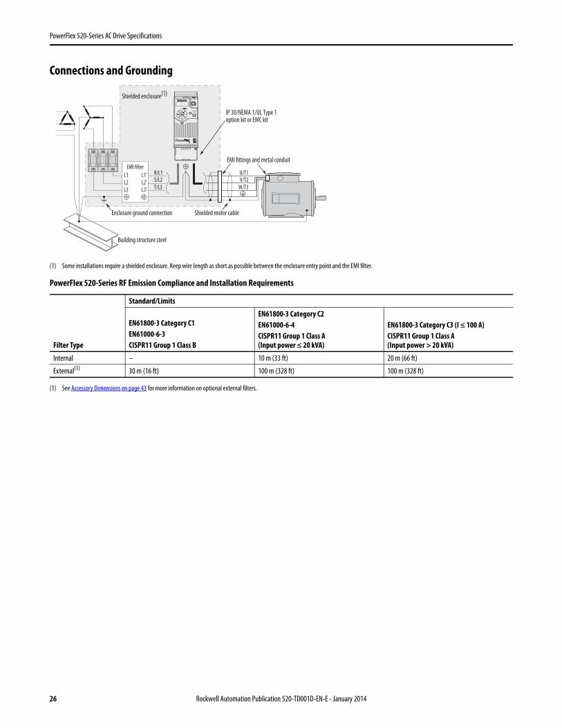
Connections and Grounding
(1) Some installations require a shielded enclosure. Keep wire length as short as possible between the enclosure entry point and the EMI filter.
(1) See Accessory Dimensions on page 43 for more information on optional external filters.
PowerFlex 520-Series RF Emission Compliance and Installation Requirements
Filter Type
Standard/Limits
EN61800-3 Category C1EN61000-6-3CISPR11 Group 1 Class B
EN61800-3 Category C2EN61000-6-4CISPR11 Group 1 Class A(Input power ≤ 20 kVA)
EN61800-3 Category C3 (I ≤ 100 A)CISPR11 Group 1 Class A(Input power > 20 kVA)
Internal – 10 m (33 ft) 20 m (66 ft)
External(1) 30 m (16 ft) 100 m (328 ft) 100 m (328 ft)
R/L1S/L2T/L3
U/T1V/T2
W/T3
EMI fittings and metal conduit
IP 30/NEMA 1/UL Type 1option kit or EMC kit
Shielded enclosure(1)
Building structure steel
Enclosure ground connection
EMI filterL1'L2'L3'
L1L2L3
Shielded motor cable
Esc Sel
26 Rockwell Automation Publication 520-TD001D-EN-E - January 2014
PowerFlex 520-Series AC Drive Specifications
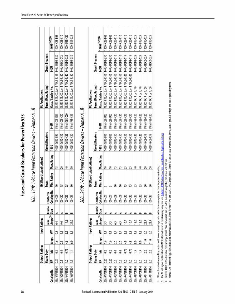
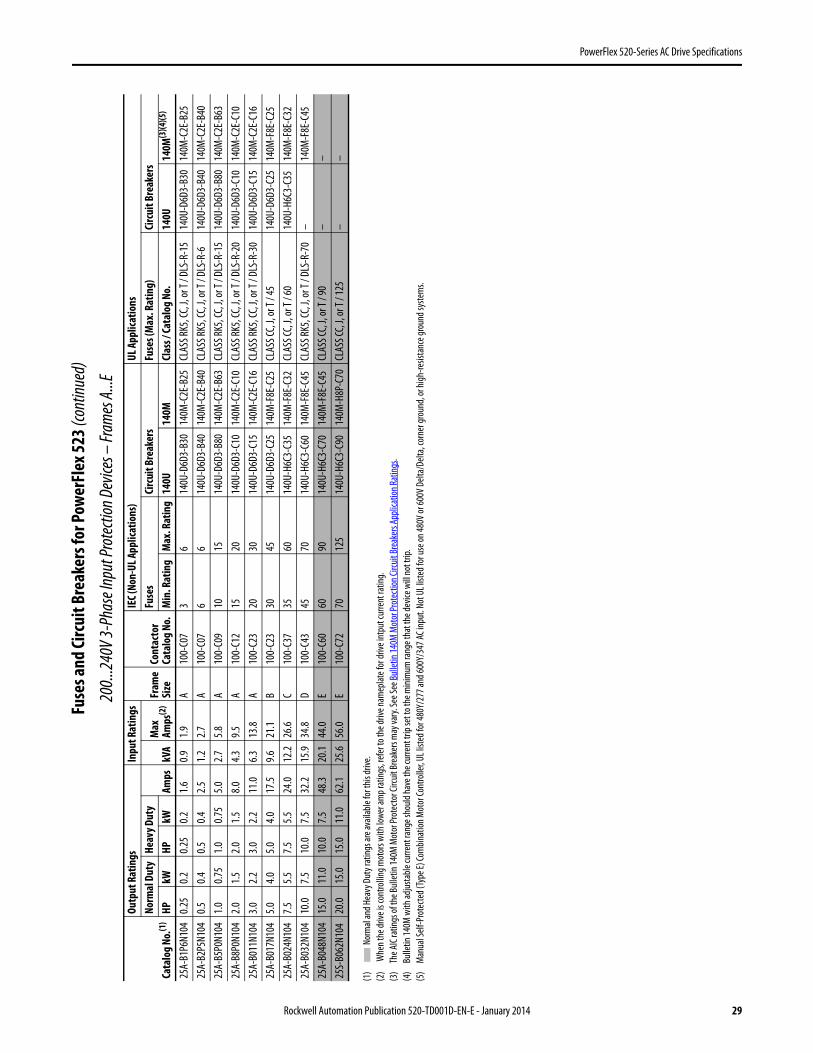
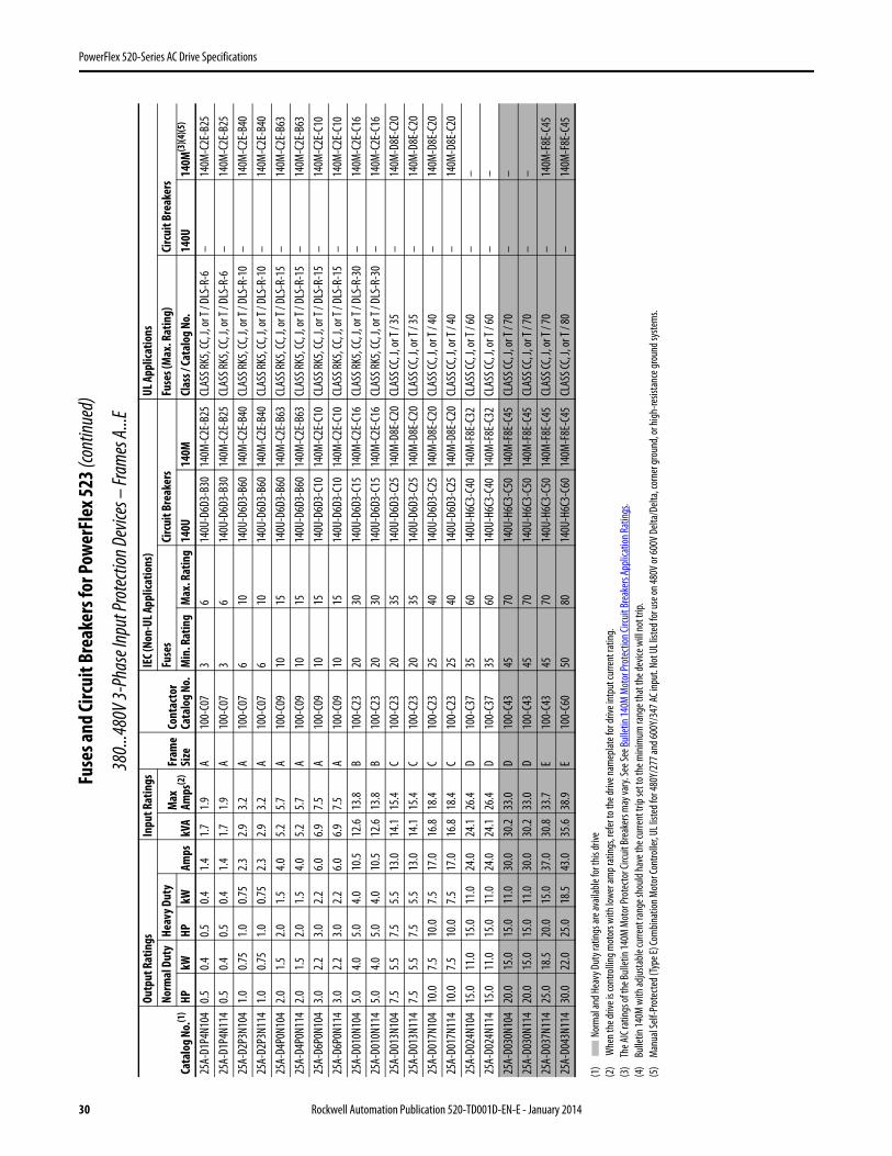
Fuses and Circuit Breaker Ratings
The PowerFlex 520-Series drive does not provide branch short circuit protection. This product should be installed with either input fuses or an input circuit breaker. National and local industrial safety regulations and/or electrical codes may determine additional requirements for these installations.
The tables on pages 32...35 provide drive ratings and recommended AC line input fuse and circuit breaker information. Both types of short circuit protection are acceptable for UL and IEC requirements. Sizes listed are the recommended sizes based on 40 °C (104 °F) and the U.S. N.E.C. Other country, state or local codes may require different ratings.
Fusing
The recommended fuse types are listed in the tables found on pages 32...35. If available current ratings do not match those listed in the tables provided, choose the next higher fuse rating.
• IEC – BS88 (British Standard) Parts 1 & 2(1), EN60269-1, Parts 1 & 2, type GG or equivalent should be used.• UL – UL Class CC, T, RK1, or J should be used.
(1) Typical designations include, but may not be limited to the following;Parts 1 & 2: AC, AD, BC, BD, CD, DD, ED, EFS, EF, FF, FG, GF, GG, GH.
Circuit Breakers
The “non-fuse” listings in the tables found on pages 32...35 include inverse time circuit breakers, instantaneous trip circuit breakers (motor circuit protectors) and 140M self-protected combination motor controllers. If one of these is chosen as the desired protection method, the following requirements apply:
• IEC – Both types of circuit breakers and 140M self-protected combination motor controllers are acceptable for IEC installations.
• UL – Only inverse time circuit breakers and the specified 140M selfprotected combination motor controllers are acceptable for UL installations.
Bulletin 140M (Self-Protected Combination Controller)/UL489 Circuit Breakers
When using Bulletin 140M or UL489 rated circuit breakers, the guidelines listed below must be followed in order to meet the NEC requirements for branch circuit protection.
• Bulletin 140M can be used in single motor applications.• Bulletin 140M can be used up stream from the drive without the need for fuses.
Rockwell Automation Publication 520-TD001D-EN-E - January 2014 27
PowerFlex 520-Series AC Drive Specifications
Fuse
s and
Circ
uit B
reak
ers f
or Po
wer
Flex
523
100..
.120V
1-Ph
ase I
nput
Prot
ectio
n Dev
ices –
Fram
es A.
..B
200..
.240V
1-Ph
ase I
nput
Prot
ectio
n Dev
ices –
Fram
es A.
..B
(1)
Whe
n the
drive
is co
ntro
lling m
otor
s with
lowe
r am
p rat
ings,
refe
r to t
he dr
ive na
mep
late f
or dr
ive in
tput
curre
nt ra
ting.
(2)
The A
IC ra
tings
of th
e Bull
etin
140M
Mot
or Pr
otec
tor C
ircuit
Brea
kers
may
vary.
See S
ee Bu
lletin
140M
Mot
or Pr
otec
tion C
ircuit
Brea
kers
Appli
catio
n Rat
ings .
(3)
Bulle
tin 14
0M w
ith ad
justa
ble cu
rrent
rang
e sho
uld ha
ve th
e cur
rent
trip
set t
o the
mini
mum
rang
e tha
t the
devic
e will
not t
rip.
(4)
Man
ual S
elf-P
rote
cted (
Type
E) Co
mbin
ation
Mot
or Co
ntro
ller, U
L list
ed fo
r 480
Y/27
7 and
600Y
/347
AC in
put.
Not U
L list
ed fo
r use
on 48
0V or
600V
Delt
a/De
lta, c
orne
r gro
und,
or hi
gh-re
sista
nce g
roun
d sys
tem
s.
Cata
log N
o.
Outp
ut R
atin
gsIn
put R
atin
gs
Fram
eSi
zeCo
ntac
tor
Cata
log N
o.
IEC (
Non-
UL A
pplic
atio
ns)
UL A
pplic
atio
nsHe
avy D
uty
Amps
kVA
Max
Amps
(1)
Fuse
sCi
rcui
t Bre
aker
sFu
ses (
Max
. Rat
ing)
Circ
uit B
reak
ers
HPkW
Min
. Rat
ing
Max
. Rat
ing
140U
140M
Clas
s / Ca
talo
g No
.14
0U14
0M(2
)(3)(4
)
25A-
V1P6
N104
0.25
0.21.6
0.86.4
A10
0-C0
910
1514
0U-D
6D2-
B80
140M
-C2E
-B63
CLAS
S RK5
, CC,
J, or
T / D
LS-R
-15
140U
-D6D
2-B8
014
0M-C
2E-B
6325
A-V2
P5N1
040.5
0.42.5
1.39.6
A10
0-C1
215
2014
0U-D
6D2-
C12
140M
-C2E
-C10
CLAS
S RK5
, CC,
J, or
T / D
LS-R
-20
140U
-D6C
2-C1
214
0M-C
2E-C
1025
A-V4
P8N1
041.0
0.75
4.82.5
19.2
B10
0-C2
325
4014
0U-D
6D2-
C25
140M
-D8E
-C20
CLAS
S RK5
, CC,
J, or
T / D
LS-R
-40
140U
-D6D
2-C2
514
0M-D
8E-C
2025
A-V6
P0N1
041.5
1.16.0
3.224
.0B
100-
C23
3050
140U
-D6D
2-C3
014
0M-F
8E-C
25CL
ASS R
K5, C
C, J,
or T
/ DLS
-R-5
014
0U-D
6D2-
C30
140M
-F8E
-C25
Cata
log N
o.
Outp
ut R
atin
gsIn
put R
atin
gs
Fram
eSi
zeCo
ntac
tor
Cata
log
No.
IEC (
Non-
UL A
pplic
atio
ns)
UL A
pplic
atio
nsHe
avy D
uty
Amps
kVA
Max
Amps
(1)
Fuse
sCi
rcui
t Bre
aker
sFu
ses (
Max
. Rat
ing)
Circ
uit B
reak
ers
HPkW
Min
. Rat
ing
Max
. Rat
ing
140U
140M
Clas
s / Ca
talo
g No
.14
0U14
0M(2
)(3)(4
)
25A-
A1P6
N104
0.25
0.21.6
1.45.3
A10
0-C0
76
1014
0U-D
6D2-
B50
140M
-C2E
-B63
CLAS
S RK5
, CC,
J, or
T / D
LS-R
-15
140U
-D6D
2-B5
014
0M-C
2E-B
6325
A-A1
P6N1
140.2
50.2
1.61.4
5.3A
100-
C07
610
140U
-D6D
2-B5
014
0M-C
2E-B
63CL
ASS R
K5, C
C, J,
or T
/ DLS
-R-1
514
0U-D
6D2-
B50
140M
-C2E
-B63
25A-
A2P5
N104
0.50.4
2.51.7
6.5A
100-
C09
1015
140U
-D6D
2-C1
014
0M-C
2E-C
10CL
ASS R
K5, C
C, J,
or T
/ DLS
-R-1
514
0U-D
6D2-
C10
140M
-C2E
-C10
25A-
A2P5
N114
0.50.4
2.51.7
6.5A
100-
C09
1015
140U
-D6D
2-C1
014
0M-C
2E-C
10CL
ASS R
K5, C
C, J,
or T
/ DLS
-R-1
514
0U-D
6D2-
C10
140M
-C2E
-C10
25A-
A4P8
N104
1.00.7
54.8
2.810
.7A
100-
C12
1525
140U
-D6D
2-C1
514
0M-C
2E-C
16CL
ASS R
K5, C
C, J,
or T
/ DLS
-R-2
514
0U-D
6D2-
C15
140M
-C2E
-C16
25A-
A4P8
N114
1.00.7
54.8
2.810
.7A
100-
C12
1525
140U
-D6D
2-C1
514
0M-C
2E-C
16CL
ASS R
K5, C
C, J,
or T
/ DLS
-R-2
514
0U-D
6D2-
C15
140M
-C2E
-C16
25A-
A8P0
N104
2.01.5
8.04.8
18.0
B10
0-C2
325
4014
0U-D
6D2-
C25
140M
-F8E
-C25
CLAS
S CC,
J, or
T / 4
014
0U-D
6D2-
C25
140M
-F8E
-C25
25A-
A8P0
N114
2.01.5
8.04.8
18.0
B10
0-C2
325
4014
0U-D
6D2-
C25
140M
-F8E
-C25
CLAS
S CC,
J, or
T / 4
014
0U-D
6D2-
C25
140M
-F8E
-C25
25A-
A011
N104
3.02.2
11.0
6.022
.9B
100-
C37
3050
140U
-H6C
2-C3
514
0M-F
8E-C
25CL
ASS C
C, J,
or T
/ 50
140U
-H6C
2-C3
514
0M-F
8E-C
2525
A-A0
11N1
143.0
2.211
.06.0
22.9
B10
0-C3
730
5014
0U-H
6C2-
C35
140M
-F8E
-C25
CLAS
S CC,
J, or
T / 5
014
0U-H
6C2-
C35
140M
-F8E
-C25
28 Rockwell Automation Publication 520-TD001D-EN-E - January 2014
PowerFlex 520-Series AC Drive Specifications
Fuse
s and
Circ
uit B
reak
ers f
or Po
wer
Flex
523 (
cont
inued
)
200..
.240V
3-Ph
ase I
nput
Prot
ectio
n Dev
ices –
Fram
es A.
..E
(1)
Nor
mal
and H
eavy
Dut
y rat
ings a
re av
ailab
le fo
r this
drive
.(2
) W
hen t
he dr
ive is
cont
rollin
g mot
ors w
ith lo
wer a
mp r
ating
s, re
fer t
o the
drive
nam
eplat
e for
drive
intp
ut cu
rrent
ratin
g.(3
)Th
e AIC
ratin
gs of
the B
ullet
in 14
0M M
otor
Prot
ecto
r Circ
uit Br
eake
rs m
ay va
ry. Se
e See
Bulle
tin 14
0M M
otor
Prot
ectio
n Circ
uit Br
eake
rs Ap
plica
tion R
ating
s .(4
)Bu
lletin
140M
with
adjus
table
curre
nt ra
nge s
hould
have
the c
urre
nt tr
ip se
t to t
he m
inim
um ra
nge t
hat t
he de
vice w
ill no
t trip
.(5
)M
anua
l Self
-Pro
tecte
d (Ty
pe E)
Com
binat
ion M
otor
Cont
rolle
r, UL l
isted
for 4
80Y/
277 a
nd 60
0Y/3
47 AC
inpu
t. No
t UL l
isted
for u
se on
480V
or 60
0V D
elta/
Delta
, cor
ner g
roun
d, or
high
-resis
tanc
e gro
und s
yste
ms.
Cata
log N
o.(1
)
Outp
ut R
atin
gsIn
put R
atin
gs
Fram
eSi
zeCo
ntac
tor
Cata
log
No.
IEC (
Non-
UL A
pplic
atio
ns)
UL A
pplic
atio
nsNo
rmal
Dut
yHe
avy D
uty
Amps
kVA
Max
Amps
(2)
Fuse
sCi
rcui
t Bre
aker
sFu
ses (
Max
. Rat
ing)
Circ
uit B
reak
ers
HPkW
HPkW
Min
. Rat
ing
Max
. Rat
ing
140U
140M
Clas
s / Ca
talo
g No
.14
0U14
0M(3
)(4)(5
)
25A-
B1P6
N104
0.25
0.20.2
50.2
1.60.9
1.9A
100-
C07
36
140U
-D6D
3-B3
014
0M-C
2E-B
25CL
ASS R
K5, C
C, J,
or T
/ DLS
-R-1
514
0U-D
6D3-
B30
140M
-C2E
-B25
25A-
B2P5
N104
0.50.4
0.50.4
2.51.2
2.7A
100-
C07
66
140U
-D6D
3-B4
014
0M-C
2E-B
40CL
ASS R
K5, C
C, J,
or T
/ DLS
-R-6
140U
-D6D
3-B4
014
0M-C
2E-B
4025
A-B5
P0N1
041.0
0.75
1.00.7
55.0
2.75.8
A10
0-C0
910
1514
0U-D
6D3-
B80
140M
-C2E
-B63
CLAS
S RK5
, CC,
J, or
T / D
LS-R
-15
140U
-D6D
3-B8
014
0M-C
2E-B
6325
A-B8
P0N1
042.0
1.52.0
1.58.0
4.39.5
A10
0-C1
215
2014
0U-D
6D3-
C10
140M
-C2E
-C10
CLAS
S RK5
, CC,
J, or
T / D
LS-R
-20
140U
-D6D
3-C1
014
0M-C
2E-C
1025
A-B0
11N1
043.0
2.23.0
2.211
.06.3
13.8
A10
0-C2
320
3014
0U-D
6D3-
C15
140M
-C2E
-C16
CLAS
S RK5
, CC,
J, or
T / D
LS-R
-30
140U
-D6D
3-C1
514
0M-C
2E-C
1625
A-B0
17N1
045.0
4.05.0
4.017
.59.6
21.1
B10
0-C2
330
4514
0U-D
6D3-
C25
140M
-F8E
-C25
CLAS
S CC,
J, or
T / 4
514
0U-D
6D3-
C25
140M
-F8E
-C25
25A-
B024
N104
7.55.5
7.55.5
24.0
12.2
26.6
C10
0-C3
735
6014
0U-H
6C3-
C35
140M
-F8E
-C32
CLAS
S CC,
J, or
T / 6
014
0U-H
6C3-
C35
140M
-F8E
-C32
25A-
B032
N104
10.0
7.510
.07.5
32.2
15.9
34.8
D10
0-C4
345
7014
0U-H
6C3-
C60
140M
-F8E
-C45
CLAS
S RK5
, CC,
J, or
T / D
LS-R
-70
–14
0M-F
8E-C
4525
A-B0
48N1
0415
.011
.010
.07.5
48.3
20.1
44.0
E10
0-C6
060
9014
0U-H
6C3-
C70
140M
-F8E
-C45
CLAS
S CC,
J, or
T / 9
0–
–25
S-B0
62N1
0420
.015
.015
.011
.062
.125
.656
.0E
100-
C72
7012
514
0U-H
6C3-
C90
140M
-H8P
-C70
CLAS
S CC,
J, or
T / 1
25–
–
Rockwell Automation Publication 520-TD001D-EN-E - January 2014 29
PowerFlex 520-Series AC Drive Specifications
Fuse
s and
Circ
uit B
reak
ers f
or Po
wer
Flex
523 (
cont
inued
)
380..
.480V
3-Ph
ase I
nput
Prot
ectio
n Dev
ices –
Fram
es A.
..E
(1)
Nor
mal
and H
eavy
Dut
y rat
ings a
re av
ailab
le fo
r this
drive
(2)
Whe
n the
drive
is co
ntro
lling m
otor
s with
lowe
r am
p rat
ings,
refe
r to t
he dr
ive na
mep
late f
or dr
ive in
tput
curre
nt ra
ting.
(3)
The A
IC ra
tings
of th
e Bull
etin
140M
Mot
or Pr
otec
tor C
ircuit
Brea
kers
may
vary.
See S
ee Bu
lletin
140M
Mot
or Pr
otec
tion C
ircuit
Brea
kers
Appli
catio
n Rat
ings .
(4)
Bulle
tin 14
0M w
ith ad
justa
ble cu
rrent
rang
e sho
uld ha
ve th
e cur
rent
trip
set t
o the
mini
mum
rang
e tha
t the
devic
e will
not t
rip.
(5)
Man
ual S
elf-P
rote
cted (
Type
E) Co
mbin
ation
Mot
or Co
ntro
ller, U
L list
ed fo
r 480
Y/27
7 and
600Y
/347
AC in
put.
Not U
L list
ed fo
r use
on 48
0V or
600V
Delt
a/De
lta, c
orne
r gro
und,
or hi
gh-re
sista
nce g
roun
d sys
tem
s.
Cata
log N
o.(1
)
Outp
ut R
atin
gsIn
put R
atin
gs
Fram
eSi
zeCo
ntac
tor
Cata
log
No.
IEC (
Non-
UL A
pplic
atio
ns)
UL A
pplic
atio
nsNo
rmal
Dut
yHe
avy D
uty
Amps
kVA
Max
Amps
(2)
Fuse
sCi
rcui
t Bre
aker
sFu
ses (
Max
. Rat
ing)
Circ
uit B
reak
ers
HPkW
HPkW
Min
. Rat
ing
Max
. Rat
ing
140U
140M
Clas
s / Ca
talo
g No
.14
0U14
0M(3
)(4)(5
)
25A-
D1P4
N104
0.50.4
0.50.4
1.41.7
1.9A
100-
C07
36
140U
-D6D
3-B3
014
0M-C
2E-B
25CL
ASS R
K5, C
C, J,
or T
/ DLS
-R-6
–14
0M-C
2E-B
2525
A-D1
P4N1
140.5
0.40.5
0.41.4
1.71.9
A10
0-C0
73
614
0U-D
6D3-
B30
140M
-C2E
-B25
CLAS
S RK5
, CC,
J, or
T / D
LS-R
-6–
140M
-C2E
-B25
25A-
D2P3
N104
1.00.7
51.0
0.75
2.32.9
3.2A
100-
C07
610
140U
-D6D
3-B6
014
0M-C
2E-B
40CL
ASS R
K5, C
C, J,
or T
/ DLS
-R-1
0–
140M
-C2E
-B40
25A-
D2P3
N114
1.00.7
51.0
0.75
2.32.9
3.2A
100-
C07
610
140U
-D6D
3-B6
014
0M-C
2E-B
40CL
ASS R
K5, C
C, J,
or T
/ DLS
-R-1
0–
140M
-C2E
-B40
25A-
D4P0
N104
2.01.5
2.01.5
4.05.2
5.7A
100-
C09
1015
140U
-D6D
3-B6
014
0M-C
2E-B
63CL
ASS R
K5, C
C, J,
or T
/ DLS
-R-1
5–
140M
-C2E
-B63
25A-
D4P0
N114
2.01.5
2.01.5
4.05.2
5.7A
100-
C09
1015
140U
-D6D
3-B6
014
0M-C
2E-B
63CL
ASS R
K5, C
C, J,
or T
/ DLS
-R-1
5–
140M
-C2E
-B63
25A-
D6P0
N104
3.02.2
3.02.2
6.06.9
7.5A
100-
C09
1015
140U
-D6D
3-C1
014
0M-C
2E-C
10CL
ASS R
K5, C
C, J,
or T
/ DLS
-R-1
5–
140M
-C2E
-C10
25A-
D6P0
N114
3.02.2
3.02.2
6.06.9
7.5A
100-
C09
1015
140U
-D6D
3-C1
014
0M-C
2E-C
10CL
ASS R
K5, C
C, J,
or T
/ DLS
-R-1
5–
140M
-C2E
-C10
25A-
D010
N104
5.04.0
5.04.0
10.5
12.6
13.8
B10
0-C2
320
3014
0U-D
6D3-
C15
140M
-C2E
-C16
CLAS
S RK5
, CC,
J, or
T / D
LS-R
-30
–14
0M-C
2E-C
1625
A-D0
10N1
145.0
4.05.0
4.010
.512
.613
.8B
100-
C23
2030
140U
-D6D
3-C1
514
0M-C
2E-C
16CL
ASS R
K5, C
C, J,
or T
/ DLS
-R-3
0–
140M
-C2E
-C16
25A-
D013
N104
7.55.5
7.55.5
13.0
14.1
15.4
C10
0-C2
320
3514
0U-D
6D3-
C25
140M
-D8E
-C20
CLAS
S CC,
J, or
T / 3
5–
140M
-D8E
-C20
25A-
D013
N114
7.55.5
7.55.5
13.0
14.1
15.4
C10
0-C2
320
3514
0U-D
6D3-
C25
140M
-D8E
-C20
CLAS
S CC,
J, or
T / 3
5–
140M
-D8E
-C20
25A-
D017
N104
10.0
7.510
.07.5
17.0
16.8
18.4
C10
0-C2
325
4014
0U-D
6D3-
C25
140M
-D8E
-C20
CLAS
S CC,
J, or
T / 4
0–
140M
-D8E
-C20
25A-
D017
N114
10.0
7.510
.07.5
17.0
16.8
18.4
C10
0-C2
325
4014
0U-D
6D3-
C25
140M
-D8E
-C20
CLAS
S CC,
J, or
T / 4
0–
140M
-D8E
-C20
25A-
D024
N104
15.0
11.0
15.0
11.0
24.0
24.1
26.4
D10
0-C3
735
6014
0U-H
6C3-
C40
140M
-F8E
-C32
CLAS
S CC,
J, or
T / 6
0–
–25
A-D0
24N1
1415
.011
.015
.011
.024
.024
.126
.4D
100-
C37
3560
140U
-H6C
3-C4
014
0M-F
8E-C
32CL
ASS C
C, J,
or T
/ 60
––
25A-
D030
N104
20.0
15.0
15.0
11.0
30.0
30.2
33.0
D10
0-C4
345
7014
0U-H
6C3-
C50
140M
-F8E
-C45
CLAS
S CC,
J, or
T / 7
0–
–25
A-D0
30N1
1420
.015
.015
.011
.030
.030
.233
.0D
100-
C43
4570
140U
-H6C
3-C5
014
0M-F
8E-C
45CL
ASS C
C, J,
or T
/ 70
––
25A-
D037
N114
25.0
18.5
20.0
15.0
37.0
30.8
33.7
E10
0-C4
345
7014
0U-H
6C3-
C50
140M
-F8E
-C45
CLAS
S CC,
J, or
T / 7
0–
140M
-F8E
-C45
25A-
D043
N114
30.0
22.0
25.0
18.5
43.0
35.6
38.9
E10
0-C6
050
8014
0U-H
6C3-
C60
140M
-F8E
-C45
CLAS
S CC,
J, or
T / 8
0–
140M
-F8E
-C45
30 Rockwell Automation Publication 520-TD001D-EN-E - January 2014
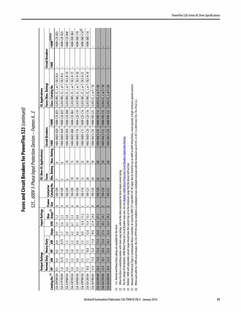
PowerFlex 520-Series AC Drive Specifications
Fuse
s and
Circ
uit B
reak
ers f
or Po
wer
Flex
523 (
cont
inued
)
525..
.600V
3-Ph
ase I
nput
Prot
ectio
n Dev
ices –
Fram
es A.
..E
(1)
Nor
mal
and H
eavy
Dut
y rat
ings a
re av
ailab
le fo
r this
drive
(2)
Whe
n the
drive
is co
ntro
lling m
otor
s with
lowe
r am
p rat
ings,
refe
r to t
he dr
ive na
mep
late f
or dr
ive in
tput
curre
nt ra
ting.
(3)
The A
IC ra
tings
of th
e Bull
etin
140M
Mot
or Pr
otec
tor C
ircuit
Brea
kers
may
vary.
See S
ee Bu
lletin
140M
Mot
or Pr
otec
tion C
ircuit
Brea
kers
Appli
catio
n Rat
ings .
(4)
Bulle
tin 14
0M w
ith ad
justa
ble cu
rrent
rang
e sho
uld ha
ve th
e cur
rent
trip
set t
o the
mini
mum
rang
e tha
t the
devic
e will
not t
rip.
(5)
Man
ual S
elf-P
rote
cted (
Type
E) Co
mbin
ation
Mot
or Co
ntro
ller, U
L list
ed fo
r 480
Y/27
7 and
600Y
/347
AC in
put.
Not U
L list
ed fo
r use
on 48
0V or
600V
Delt
a/De
lta, c
orne
r gro
und,
or hi
gh-re
sista
nce g
roun
d sys
tem
s.(6
)W
hen u
sed w
ith th
e 140
M ci
rcuit
brea
ker, t
he 25
A-E9
P910
4 mus
t be i
nsta
lled i
n a ve
ntila
ted o
r non
-ven
tilat
ed en
closu
re w
ith th
e mini
mum
size
of 45
7.2 x
457.2
x 26
9.8 m
m (1
8 x 18
x 10
.62 in
.).
Cata
log N
o.(1
)
Outp
ut R
atin
gsIn
put R
atin
gs
Fram
eSi
zeCo
ntac
tor
Cata
log
No.
IEC (
Non-
UL A
pplic
atio
ns)
UL A
pplic
atio
nsNo
rmal
Dut
yHe
avy D
uty
Amps
kVA
Max
Amps
(2)
Fuse
sCi
rcui
t Bre
aker
sFu
ses (
Max
. Rat
ing)
Circ
uit B
reak
ers
HPkW
HPkW
Min
. Rat
ing
Max
. Rat
ing
140U
140M
Clas
s / Ca
talo
g No
.14
0U14
0M(3
)(4)(5
)
25A-
E0P9
N104
0.50.4
0.50.4
0.91.4
1.2A
100-
C09
36
140U
-D6D
3-B2
014
0M-C
2E-B
25CL
ASS R
K5, C
C, J,
or T
/ DLS
-R-6
–14
0M-C
2E-B
2525
A-E1
P7N1
041.0
0.75
1.00.7
51.7
2.62.3
A10
0-C0
93
614
0U-D
6D3-
B30
140M
-C2E
-B25
CLAS
S RK5
, CC,
J, or
T / D
LS-R
-6–
140M
-C2E
-B25
25A-
E3P0
N104
2.01.5
2.01.5
3.04.3
3.8A
100-
C09
610
140U
-D6D
3-B5
014
0M-C
2E-B
40CL
ASS R
K5, C
C, J,
or T
/ DLS
-R-1
0–
140M
-C2E
-B40
25A-
E4P2
N104
3.02.2
3.02.2
4.26.1
5.3A
100-
C09
1015
140U
-D6D
3-B8
014
0M-C
2E-B
63CL
ASS R
K5, C
C, J,
or T
/ DLS
-R-1
5–
140M
-D8E
-B63
25A-
E6P6
N104
5.04.0
5.04.0
6.69.1
8.0B
100-
C09
1020
140U
-D6D
3-C1
014
0M-C
2E-C
10CL
ASS R
K5, C
C, J,
or T
/ DLS
-R-2
0–
140M
-D8E
-C10
25A-
E9P9
N104
7.55.5
7.55.5
9.912
.811
.2C
100-
C16
1525
140U
-D6D
3-C1
514
0M-C
2E-C
16CL
ASS R
K5, C
C, J,
or T
/ DLS
-R-2
5–
140M
-D8E
-C16
(6)
25A-
E012
N104
10.0
7.510
.07.5
12.0
15.4
13.5
C10
0-C2
320
3014
0U-D
6D3-
C20
140M
-C2E
-C16
CLAS
S RK5
, CC,
J, or
T / D
LS-R
-30
–14
0M-D
8E-C
1625
A-E0
19N1
0415
.011
.015
.011
.019
.027
.424
.0D
100-
C30
3050
140U
-H6C
3-C3
014
0M-F
8E-C
25CL
ASS C
C, J,
or T
/ 50
––
25A-
E022
N104
20.0
15.0
15.0
11.0
22.0
31.2
27.3
D10
0-C3
035
6014
0U-H
6C3-
C35
140M
-F8E
-C32
CLAS
S CC,
J, or
T / 6
0–
–25
A-E0
27N1
0425
.018
.520
.015
.027
.028
.224
.7E
100-
C30
3550
140U
-H6C
3-C3
514
0M-F
8E-C
32CL
ASS C
C, J,
or T
/ 50
––
25A-
E032
N104
30.0
22.0
25.0
18.5
32.0
33.4
29.2
E10
0-C3
740
6014
0U-H
6C3-
C50
140M
-F8E
-C32
CLAS
S CC,
J, or
T / 6
0–
–
Rockwell Automation Publication 520-TD001D-EN-E - January 2014 31
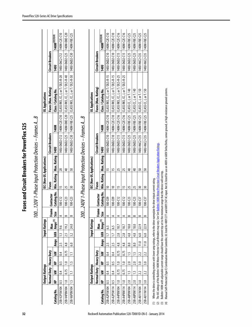
PowerFlex 520-Series AC Drive Specifications
Fuse
s and
Circ
uit B
reak
ers f
or Po
wer
Flex
525
100..
.120V
1-Ph
ase I
nput
Prot
ectio
n Dev
ices –
Fram
es A.
..B
200..
.240V
1-Ph
ase I
nput
Prot
ectio
n Dev
ices –
Fram
es A.
..B
(1)
Whe
n the
drive
is co
ntro
lling m
otor
s with
lowe
r am
p rat
ings,
refe
r to t
he dr
ive na
mep
late f
or dr
ive in
tput
curre
nt ra
ting.
(2)
The A
IC ra
tings
of th
e Bull
etin
140M
Mot
or Pr
otec
tor C
ircuit
Brea
kers
may
vary.
See S
ee Bu
lletin
140M
Mot
or Pr
otec
tion C
ircuit
Brea
kers
Appli
catio
n Rat
ings .
(3)
Bulle
tin 14
0M w
ith ad
justa
ble cu
rrent
rang
e sho
uld ha
ve th
e cur
rent
trip
set t
o the
mini
mum
rang
e tha
t the
devic
e will
not t
rip.
(4)
Man
ual S
elf-P
rote
cted (
Type
E) Co
mbin
ation
Mot
or Co
ntro
ller, U
L list
ed fo
r 480
Y/27
7 and
600Y
/347
AC in
put.
Not U
L list
ed fo
r use
on 48
0V or
600V
Delt
a/De
lta, c
orne
r gro
und,
or hi
gh-re
sista
nce g
roun
d sys
tem
s.
Cata
log N
o.
Outp
ut R
atin
gsIn
put R
atin
gs
Fram
eSi
zeCo
ntac
tor
Cata
log N
o.
IEC (
Non-
UL A
pplic
atio
ns)
UL A
pplic
atio
nsNo
rmal
Dut
yHe
avy D
uty
Amps
kVA
Max
Amps
(1)
Fuse
sCi
rcui
t Bre
aker
sFu
ses (
Max
. Rat
ing)
Circ
uit B
reak
ers
HPkW
HPkW
Min
. Rat
ing
Max
. Rat
ing
140U
140M
Clas
s / Ca
talo
g No.
140U
140M
(2)(3
)(4)
25B-
V2P5
N104
0.50.4
0.50.4
2.51.3
9.6A
100-
C12
1520
140U
-D6D
2-C1
214
0M-C
2E-C
10CL
ASS R
K5, C
C, J,
or T
/ DLS
-R-2
014
0U-D
6C2-
C12
140M
-C2E
-C10
25B-
V4P8
N104
1.00.7
51.0
0.75
4.82.5
19.2
B10
0-C2
325
4014
0U-D
6D2-
C25
140M
-D8E
-C20
CLAS
S RK5
, CC,
J, or
T / D
LS-R
-40
140U
-D6D
2-C2
514
0M-D
8E-C
2025
B-V6
P0N1
041.5
1.11.5
1.16.0
3.224
.0B
100-
C23
3050
140U
-D6D
2-C3
014
0M-F
8E-C
25CL
ASS R
K5, C
C, J,
or T
/ DLS
-R-5
014
0U-D
6D2-
C30
140M
-F8E
-C25
Cata
log N
o.
Outp
ut R
atin
gsIn
put R
atin
gs
Fram
eSi
zeCo
ntac
tor
Cata
log N
o.
IEC (
Non-
UL A
pplic
atio
ns)
UL A
pplic
atio
nsNo
rmal
Dut
yHe
avy D
uty
Amps
kVA
Max
Amps
(1)
Fuse
sCi
rcui
t Bre
aker
sFu
ses (
Max
. Rat
ing)
Circ
uit B
reak
ers
HPkW
HPkW
Min
. Rat
ing
Max
. Rat
ing
140U
140M
Clas
s / Ca
talo
g No
.14
0U14
0M(2
)(3)(4
)
25B-
A2P5
N104
0.50.4
0.50.4
2.51.7
6.5A
100-
C09
1015
140U
-D6D
2-C1
014
0M-C
2E-C
10CL
ASS R
K5, C
C, J,
or T
/ DLS
-R-1
514
0U-D
6D2-
C10
140M
-C2E
-C10
25B-
A2P5
N114
0.50.4
0.50.4
2.51.7
6.5A
100-
C09
1015
140U
-D6D
2-C1
014
0M-C
2E-C
10CL
ASS R
K5, C
C, J,
or T
/ DLS
-R-1
514
0U-D
6D2-
C10
140M
-C2E
-C10
25B-
A4P8
N104
1.00.7
51.0
0.75
4.82.8
10.7
A10
0-C1
215
2514
0U-D
6D2-
C15
140M
-C2E
-C16
CLAS
S RK5
, CC,
J, or
T / D
LS-R
-25
140U
-D6D
2-C1
514
0M-C
2E-C
1625
B-A4
P8N1
141.0
0.75
1.00.7
54.8
2.810
.7A
100-
C12
1525
140U
-D6D
2-C1
514
0M-C
2E-C
16CL
ASS R
K5, C
C, J,
or T
/ DLS
-R-2
514
0U-D
6D2-
C15
140M
-C2E
-C16
25B-
A8P0
N104
2.01.5
2.01.5
8.04.8
18.0
B10
0-C2
325
4014
0U-D
6D2-
C25
140M
-F8E
-C25
CLAS
S CC,
J, or
T / 4
014
0U-D
6D2-
C25
140M
-F8E
-C25
25B-
A8P0
N114
2.01.5
2.01.5
8.04.8
18.0
B10
0-C2
325
4014
0U-D
6D2-
C25
140M
-F8E
-C25
CLAS
S CC,
J, or
T / 4
014
0U-D
6D2-
C25
140M
-F8E
-C25
25B-
A011
N104
3.02.2
3.02.2
11.0
6.022
.9B
100-
C37
3050
140U
-H6C
2-C3
514
0M-F
8E-C
25CL
ASS C
C, J,
or T
/ 50
140U
-H6C
2-C3
514
0M-F
8E-C
2525
B-A0
11N1
143.0
2.23.0
2.211
.06.0
22.9
B10
0-C3
730
5014
0U-H
6C2-
C35
140M
-F8E
-C25
CLAS
S CC,
J, or
T / 5
014
0U-H
6C2-
C35
140M
-F8E
-C25
32 Rockwell Automation Publication 520-TD001D-EN-E - January 2014
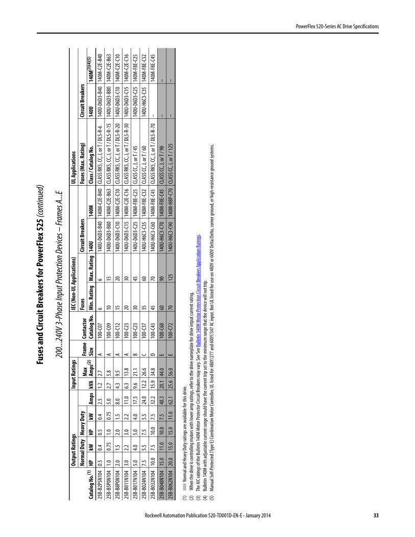
PowerFlex 520-Series AC Drive Specifications
Fuse
s and
Circ
uit B
reak
ers f
or Po
wer
Flex
525 (
cont
inued
)
200..
.240V
3-Ph
ase I
nput
Prot
ectio
n Dev
ices –
Fram
es A.
..E
(1)
Nor
mal
and H
eavy
Dut
y rat
ings a
re av
ailab
le fo
r this
drive
.(2
) W
hen t
he dr
ive is
cont
rollin
g mot
ors w
ith lo
wer a
mp r
ating
s, re
fer t
o the
drive
nam
eplat
e for
drive
intp
ut cu
rrent
ratin
g.(3
)Th
e AIC
ratin
gs of
the B
ullet
in 14
0M M
otor
Prot
ecto
r Circ
uit Br
eake
rs m
ay va
ry. Se
e See
Bulle
tin 14
0M M
otor
Prot
ectio
n Circ
uit Br
eake
rs Ap
plica
tion R
ating
s .(4
)Bu
lletin
140M
with
adjus
table
curre
nt ra
nge s
hould
have
the c
urre
nt tr
ip se
t to t
he m
inim
um ra
nge t
hat t
he de
vice w
ill no
t trip
.(5
)M
anua
l Self
-Pro
tecte
d (Ty
pe E)
Com
binat
ion M
otor
Cont
rolle
r, UL l
isted
for 4
80Y/
277 a
nd 60
0Y/3
47 AC
inpu
t. No
t UL l
isted
for u
se on
480V
or 60
0V D
elta/
Delta
, cor
ner g
roun
d, or
high
-resis
tanc
e gro
und s
yste
ms.
Cata
log N
o.(1
)
Outp
ut R
atin
gsIn
put R
atin
gs
Fram
eSi
zeCo
ntac
tor
Cata
log
No.
IEC (
Non-
UL A
pplic
atio
ns)
UL A
pplic
atio
nsNo
rmal
Dut
yHe
avy D
uty
Amps
kVA
Max
Amps
(2)
Fuse
sCi
rcui
t Bre
aker
sFu
ses (
Max
. Rat
ing)
Circ
uit B
reak
ers
HPkW
HPkW
Min
. Rat
ing
Max
. Rat
ing
140U
140M
Clas
s / Ca
talo
g No
.14
0U14
0M(3
)(4)(5
)
25B-
B2P5
N104
0.50.4
0.50.4
2.51.2
2.7A
100-
C07
66
140U
-D6D
3-B4
014
0M-C
2E-B
40CL
ASS R
K5, C
C, J,
or T
/ DLS
-R-6
140U
-D6D
3-B4
014
0M-C
2E-B
4025
B-B5
P0N1
041.0
0.75
1.00.7
55.0
2.75.8
A10
0-C0
910
1514
0U-D
6D3-
B80
140M
-C2E
-B63
CLAS
S RK5
, CC,
J, or
T / D
LS-R
-15
140U
-D6D
3-B8
014
0M-C
2E-B
6325
B-B8
P0N1
042.0
1.52.0
1.58.0
4.39.5
A10
0-C1
215
2014
0U-D
6D3-
C10
140M
-C2E
-C10
CLAS
S RK5
, CC,
J, or
T / D
LS-R
-20
140U
-D6D
3-C1
014
0M-C
2E-C
1025
B-B0
11N1
043.0
2.23.0
2.211
.06.3
13.8
A10
0-C2
320
3014
0U-D
6D3-
C15
140M
-C2E
-C16
CLAS
S RK5
, CC,
J, or
T / D
LS-R
-30
140U
-D6D
3-C1
514
0M-C
2E-C
1625
B-B0
17N1
045.0
4.05.0
4.017
.59.6
21.1
B10
0-C2
330
4514
0U-D
6D3-
C25
140M
-F8E
-C25
CLAS
S CC,
J, or
T / 4
514
0U-D
6D3-
C25
140M
-F8E
-C25
25B-
B024
N104
7.55.5
7.55.5
24.0
12.2
26.6
C10
0-C3
735
6014
0U-H
6C3-
C35
140M
-F8E
-C32
CLAS
S CC,
J, or
T / 6
014
0U-H
6C3-
C35
140M
-F8E
-C32
25B-
B032
N104
10.0
7.510
.07.5
32.2
15.9
34.8
D10
0-C4
345
7014
0U-H
6C3-
C60
140M
-F8E
-C45
CLAS
S RK5
, CC,
J, or
T / D
LS-R
-70
–14
0M-F
8E-C
4525
B-B0
48N1
0415
.011
.010
.07.5
48.3
20.1
44.0
E10
0-C6
060
9014
0U-H
6C3-
C70
140M
-F8E
-C45
CLAS
S CC,
J, or
T / 9
0–
–25
B-B0
62N1
0420
.015
.015
.011
.062
.125
.656
.0E
100-
C72
7012
514
0U-H
6C3-
C90
140M
-H8P
-C70
CLAS
S CC,
J, or
T / 1
25–
–
Rockwell Automation Publication 520-TD001D-EN-E - January 2014 33
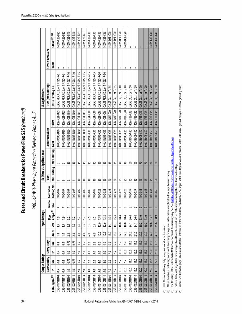
PowerFlex 520-Series AC Drive Specifications
Fuse
s and
Circ
uit B
reak
ers f
or Po
wer
Flex
525 (
cont
inued
)
380..
.480V
3-Ph
ase I
nput
Prot
ectio
n Dev
ices –
Fram
es A.
..E
(1)
Nor
mal
and H
eavy
Dut
y rat
ings a
re av
ailab
le fo
r this
drive
(2)
Whe
n the
drive
is co
ntro
lling m
otor
s with
lowe
r am
p rat
ings,
refe
r to t
he dr
ive na
mep
late f
or dr
ive in
tput
curre
nt ra
ting.
(3)
The A
IC ra
tings
of th
e Bull
etin
140M
Mot
or Pr
otec
tor C
ircuit
Brea
kers
may
vary.
See S
ee Bu
lletin
140M
Mot
or Pr
otec
tion C
ircuit
Brea
kers
Appli
catio
n Rat
ings .
(4)
Bulle
tin 14
0M w
ith ad
justa
ble cu
rrent
rang
e sho
uld ha
ve th
e cur
rent
trip
set t
o the
mini
mum
rang
e tha
t the
devic
e will
not t
rip.
(5)
Man
ual S
elf-P
rote
cted (
Type
E) Co
mbin
ation
Mot
or Co
ntro
ller, U
L list
ed fo
r 480
Y/27
7 and
600Y
/347
AC in
put.
Not U
L list
ed fo
r use
on 48
0V or
600V
Delt
a/De
lta, c
orne
r gro
und,
or hi
gh-re
sista
nce g
roun
d sys
tem
s.
Cata
log N
o.(1
)
Outp
ut R
atin
gsIn
put R
atin
gs
Fram
eSi
zeCo
ntac
tor
Cata
log
No.
IEC (
Non-
UL A
pplic
atio
ns)
UL A
pplic
atio
nsNo
rmal
Dut
yHe
avy D
uty
Amps
kVA
Max
Amps
(2)
Fuse
sCi
rcui
t Bre
aker
sFu
ses (
Max
. Rat
ing)
Circ
uit B
reak
ers
HPkW
HPkW
Min
. Rat
ing
Max
. Rat
ing
140U
140M
Clas
s / Ca
talo
g No
.14
0U14
0M(3
)(4)(5
)
25B-
D1P4
N104
0.50.4
0.50.4
1.41.7
1.9A
100-
C07
36
140U
-D6D
3-B3
014
0M-C
2E-B
25CL
ASS R
K5, C
C, J,
or T
/ DLS
-R-6
–14
0M-C
2E-B
2525
B-D1
P4N1
140.5
0.40.5
0.41.4
1.71.9
A10
0-C0
73
614
0U-D
6D3-
B30
140M
-C2E
-B25
CLAS
S RK5
, CC,
J, or
T / D
LS-R
-6–
140M
-C2E
-B25
25B-
D2P3
N104
1.00.7
51.0
0.75
2.32.9
3.2A
100-
C07
610
140U
-D6D
3-B6
014
0M-C
2E-B
40CL
ASS R
K5, C
C, J,
or T
/ DLS
-R-1
0–
140M
-C2E
-B40
25B-
D2P3
N114
1.00.7
51.0
0.75
2.32.9
3.2A
100-
C07
610
140U
-D6D
3-B6
014
0M-C
2E-B
40CL
ASS R
K5, C
C, J,
or T
/ DLS
-R-1
0–
140M
-C2E
-B40
25B-
D4P0
N104
2.01.5
2.01.5
4.05.2
5.7A
100-
C09
1015
140U
-D6D
3-B6
014
0M-C
2E-B
63CL
ASS R
K5, C
C, J,
or T
/ DLS
-R-1
5–
140M
-C2E
-B63
25B-
D4P0
N114
2.01.5
2.01.5
4.05.2
5.7A
100-
C09
1015
140U
-D6D
3-B6
014
0M-C
2E-B
63CL
ASS R
K5, C
C, J,
or T
/ DLS
-R-1
5–
140M
-C2E
-B63
25B-
D6P0
N104
3.02.2
3.02.2
6.06.9
7.5A
100-
C09
1015
140U
-D6D
3-C1
014
0M-C
2E-C
10CL
ASS R
K5, C
C, J,
or T
/ DLS
-R-1
5–
140M
-C2E
-C10
25B-
D6P0
N114
3.02.2
3.02.2
6.06.9
7.5A
100-
C09
1015
140U
-D6D
3-C1
014
0M-C
2E-C
10CL
ASS R
K5, C
C, J,
or T
/ DLS
-R-1
5–
140M
-C2E
-C10
25B-
D010
N104
5.04.0
5.04.0
10.5
12.6
13.8
B10
0-C2
320
3014
0U-D
6D3-
C15
140M
-C2E
-C16
CLAS
S RK5
, CC,
J, or
T / D
LS-R
-30
–14
0M-C
2E-C
1625
B-D0
10N1
145.0
4.05.0
4.010
.512
.613
.8B
100-
C23
2030
140U
-D6D
3-C1
514
0M-C
2E-C
16CL
ASS R
K5, C
C, J,
or T
/ DLS
-R-3
0–
140M
-C2E
-C16
25B-
D013
N104
7.55.5
7.55.5
13.0
14.1
15.4
C10
0-C2
320
3514
0U-D
6D3-
C25
140M
-D8E
-C20
CLAS
S CC,
J, or
T / 3
5–
140M
-D8E
-C20
25B-
D013
N114
7.55.5
7.55.5
13.0
14.1
15.4
C10
0-C2
320
3514
0U-D
6D3-
C25
140M
-D8E
-C20
CLAS
S CC,
J, or
T / 3
5–
140M
-D8E
-C20
25B-
D017
N104
10.0
7.510
.07.5
17.0
16.8
18.4
C10
0-C2
325
4014
0U-D
6D3-
C25
140M
-D8E
-C20
CLAS
S CC,
J, or
T / 4
0–
140M
-D8E
-C20
25B-
D017
N114
10.0
7.510
.07.5
17.0
16.8
18.4
C10
0-C2
325
4014
0U-D
6D3-
C25
140M
-D8E
-C20
CLAS
S CC,
J, or
T / 4
0–
140M
-D8E
-C20
25B-
D024
N104
15.0
11.0
15.0
11.0
24.0
24.1
26.4
D10
0-C3
735
6014
0U-H
6C3-
C40
140M
-F8E
-C32
CLAS
S CC,
J, or
T / 6
0–
–25
B-D0
24N1
1415
.011
.015
.011
.024
.024
.126
.4D
100-
C37
3560
140U
-H6C
3-C4
014
0M-F
8E-C
32CL
ASS C
C, J,
or T
/ 60
––
25B-
D030
N104
20.0
15.0
15.0
11.0
30.0
30.2
33.0
D10
0-C4
345
7014
0U-H
6C3-
C50
140M
-F8E
-C45
CLAS
S CC,
J, or
T / 7
0–
–25
B-D0
30N1
1420
.015
.015
.011
.030
.030
.233
.0D
100-
C43
4570
140U
-H6C
3-C5
014
0M-F
8E-C
45CL
ASS C
C, J,
or T
/ 70
––
25B-
D037
N114
25.0
18.5
20.0
15.0
37.0
30.8
33.7
E10
0-C4
345
7014
0U-H
6C3-
C50
140M
-F8E
-C45
CLAS
S CC,
J, or
T / 7
0–
140M
-F8E
-C45
25B-
D043
N114
30.0
22.0
25.0
18.5
43.0
35.6
38.9
E10
0-C6
050
8014
0U-H
6C3-
C60
140M
-F8E
-C45
CLAS
S CC,
J, or
T / 8
0–
140M
-F8E
-C45
34 Rockwell Automation Publication 520-TD001D-EN-E - January 2014
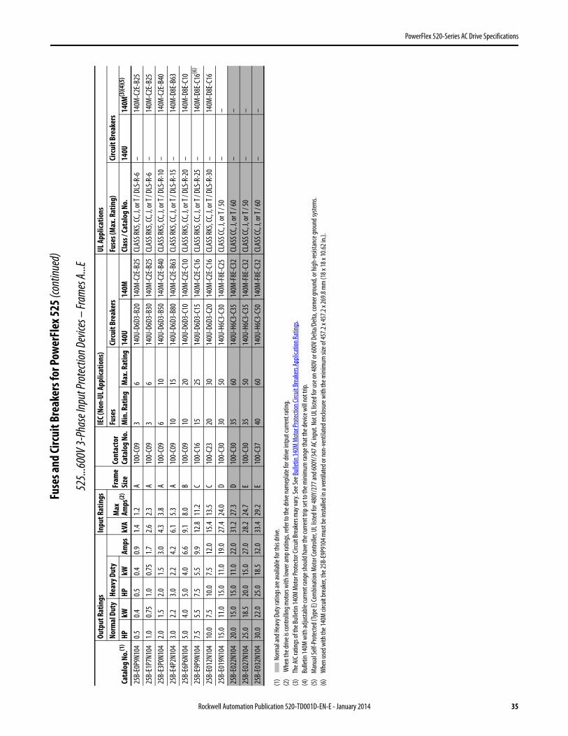
PowerFlex 520-Series AC Drive Specifications
Fuse
s and
Circ
uit B
reak
ers f
or Po
wer
Flex
525 (
cont
inued
)
525..
.600V
3-Ph
ase I
nput
Prot
ectio
n Dev
ices –
Fram
es A.
..E
(1)
Nor
mal
and H
eavy
Dut
y rat
ings a
re av
ailab
le fo
r this
drive
.(2
) W
hen t
he dr
ive is
cont
rollin
g mot
ors w
ith lo
wer a
mp r
ating
s, re
fer t
o the
drive
nam
eplat
e for
drive
intp
ut cu
rrent
ratin
g.(3
)Th
e AIC
ratin
gs of
the B
ullet
in 14
0M M
otor
Prot
ecto
r Circ
uit Br
eake
rs m
ay va
ry. Se
e See
Bulle
tin 14
0M M
otor
Prot
ectio
n Circ
uit Br
eake
rs Ap
plica
tion R
ating
s .(4
)Bu
lletin
140M
with
adjus
table
curre
nt ra
nge s
hould
have
the c
urre
nt tr
ip se
t to t
he m
inim
um ra
nge t
hat t
he de
vice w
ill no
t trip
.(5
)M
anua
l Self
-Pro
tecte
d (Ty
pe E)
Com
binat
ion M
otor
Cont
rolle
r, UL l
isted
for 4
80Y/
277 a
nd 60
0Y/3
47 AC
inpu
t. No
t UL l
isted
for u
se on
480V
or 60
0V D
elta/
Delta
, cor
ner g
roun
d, or
high
-resis
tanc
e gro
und s
yste
ms.
(6)
Whe
n use
d with
the 1
40M
circu
it br
eake
r, the
25B-
E9P9
104 m
ust b
e ins
talle
d in a
vent
ilate
d or n
on-v
entil
ated
enclo
sure
with
the m
inim
um si
ze of
457.2
x 45
7.2 x
269.8
mm
(18 x
18 x
10.62
in.).
Cata
log N
o.(1
)
Outp
ut R
atin
gsIn
put R
atin
gs
Fram
eSi
zeCo
ntac
tor
Cata
log
No.
IEC (
Non-
UL A
pplic
atio
ns)
UL A
pplic
atio
nsNo
rmal
Dut
yHe
avy D
uty
Amps
kVA
Max
Amps
(2)
Fuse
sCi
rcui
t Bre
aker
sFu
ses (
Max
. Rat
ing)
Circ
uit B
reak
ers
HPkW
HPkW
Min
. Rat
ing
Max
. Rat
ing
140U
140M
Clas
s / Ca
talo
g No
.14
0U14
0M(3
)(4)(5
)
25B-
E0P9
N104
0.50.4
0.50.4
0.91.4
1.2A
100-
C09
36
140U
-D6D
3-B2
014
0M-C
2E-B
25CL
ASS R
K5, C
C, J,
or T
/ DLS
-R-6
–14
0M-C
2E-B
2525
B-E1
P7N1
041.0
0.75
1.00.7
51.7
2.62.3
A10
0-C0
93
614
0U-D
6D3-
B30
140M
-C2E
-B25
CLAS
S RK5
, CC,
J, or
T / D
LS-R
-6–
140M
-C2E
-B25
25B-
E3P0
N104
2.01.5
2.01.5
3.04.3
3.8A
100-
C09
610
140U
-D6D
3-B5
014
0M-C
2E-B
40CL
ASS R
K5, C
C, J,
or T
/ DLS
-R-1
0–
140M
-C2E
-B40
25B-
E4P2
N104
3.02.2
3.02.2
4.26.1
5.3A
100-
C09
1015
140U
-D6D
3-B8
014
0M-C
2E-B
63CL
ASS R
K5, C
C, J,
or T
/ DLS
-R-1
5–
140M
-D8E
-B63
25B-
E6P6
N104
5.04.0
5.04.0
6.69.1
8.0B
100-
C09
1020
140U
-D6D
3-C1
014
0M-C
2E-C
10CL
ASS R
K5, C
C, J,
or T
/ DLS
-R-2
0–
140M
-D8E
-C10
25B-
E9P9
N104
7.55.5
7.55.5
9.912
.811
.2C
100-
C16
1525
140U
-D6D
3-C1
514
0M-C
2E-C
16CL
ASS R
K5, C
C, J,
or T
/ DLS
-R-2
5–
140M
-D8E
-C16
(6)
25B-
E012
N104
10.0
7.510
.07.5
12.0
15.4
13.5
C10
0-C2
320
3014
0U-D
6D3-
C20
140M
-C2E
-C16
CLAS
S RK5
, CC,
J, or
T / D
LS-R
-30
–14
0M-D
8E-C
1625
B-E0
19N1
0415
.011
.015
.011
.019
.027
.424
.0D
100-
C30
3050
140U
-H6C
3-C3
014
0M-F
8E-C
25CL
ASS C
C, J,
or T
/ 50
––
25B-
E022
N104
20.0
15.0
15.0
11.0
22.0
31.2
27.3
D10
0-C3
035
6014
0U-H
6C3-
C35
140M
-F8E
-C32
CLAS
S CC,
J, or
T / 6
0–
–25
B-E0
27N1
0425
.018
.520
.015
.027
.028
.224
.7E
100-
C30
3550
140U
-H6C
3-C3
514
0M-F
8E-C
32CL
ASS C
C, J,
or T
/ 50
––
25B-
E032
N104
30.0
22.0
25.0
18.5
32.0
33.4
29.2
E10
0-C3
740
6014
0U-H
6C3-
C50
140M
-F8E
-C32
CLAS
S CC,
J, or
T / 6
0–
–
Rockwell Automation Publication 520-TD001D-EN-E - January 2014 35
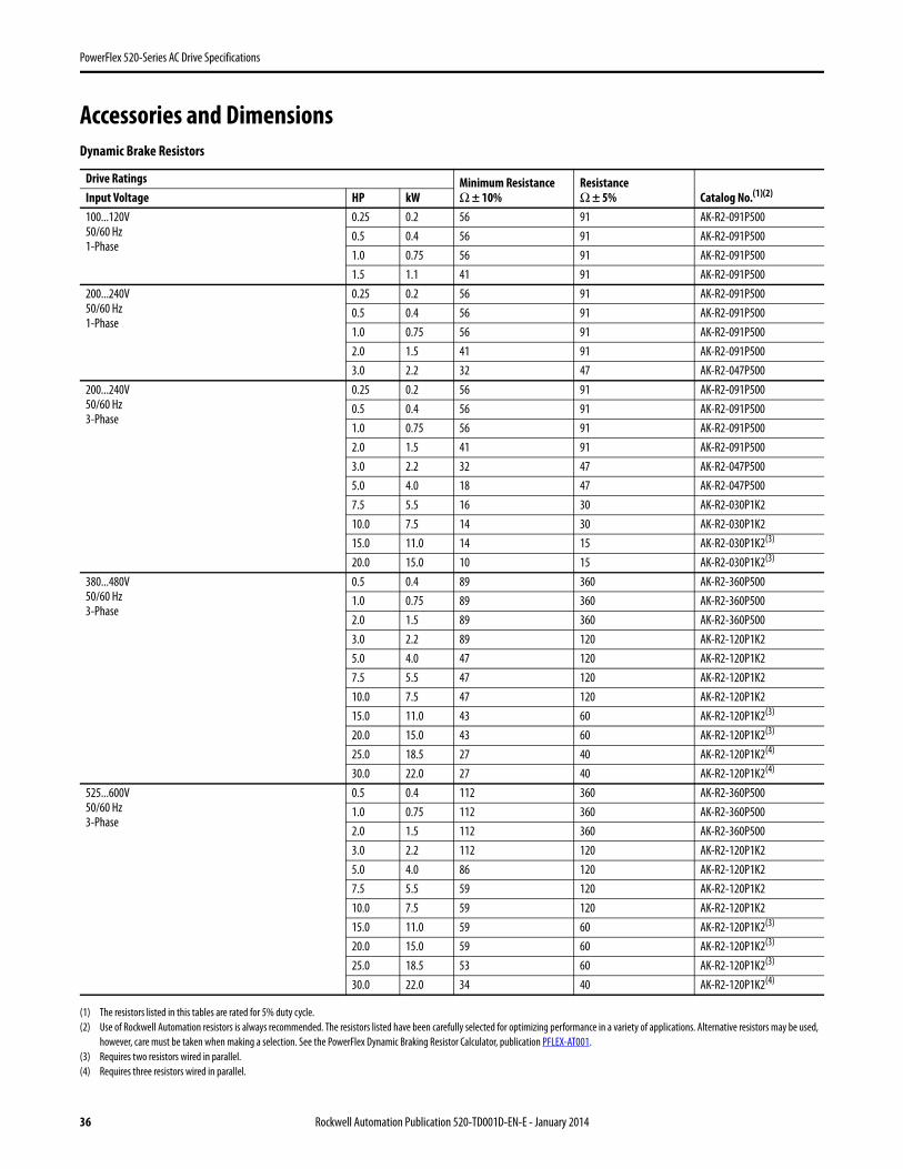
PowerFlex 520-Series AC Drive Specifications
Accessories and Dimensions
(1) The resistors listed in this tables are rated for 5% duty cycle.(2) Use of Rockwell Automation resistors is always recommended. The resistors listed have been carefully selected for optimizing performance in a variety of applications. Alternative resistors may be used,
however, care must be taken when making a selection. See the PowerFlex Dynamic Braking Resistor Calculator, publication PFLEX-AT001.(3) Requires two resistors wired in parallel.(4) Requires three resistors wired in parallel.
Dynamic Brake Resistors
Drive Ratings Minimum ResistanceΩ ± 10%
Resistance Ω ± 5% Catalog No.(1)(2)Input Voltage HP kW
100...120V50/60 Hz1-Phase
0.25 0.2 56 91 AK-R2-091P5000.5 0.4 56 91 AK-R2-091P5001.0 0.75 56 91 AK-R2-091P5001.5 1.1 41 91 AK-R2-091P500
200...240V50/60 Hz1-Phase
0.25 0.2 56 91 AK-R2-091P5000.5 0.4 56 91 AK-R2-091P5001.0 0.75 56 91 AK-R2-091P5002.0 1.5 41 91 AK-R2-091P5003.0 2.2 32 47 AK-R2-047P500
200...240V50/60 Hz3-Phase
0.25 0.2 56 91 AK-R2-091P5000.5 0.4 56 91 AK-R2-091P5001.0 0.75 56 91 AK-R2-091P5002.0 1.5 41 91 AK-R2-091P5003.0 2.2 32 47 AK-R2-047P5005.0 4.0 18 47 AK-R2-047P5007.5 5.5 16 30 AK-R2-030P1K210.0 7.5 14 30 AK-R2-030P1K215.0 11.0 14 15 AK-R2-030P1K2(3)
20.0 15.0 10 15 AK-R2-030P1K2(3)
380...480V50/60 Hz3-Phase
0.5 0.4 89 360 AK-R2-360P5001.0 0.75 89 360 AK-R2-360P5002.0 1.5 89 360 AK-R2-360P5003.0 2.2 89 120 AK-R2-120P1K25.0 4.0 47 120 AK-R2-120P1K27.5 5.5 47 120 AK-R2-120P1K210.0 7.5 47 120 AK-R2-120P1K215.0 11.0 43 60 AK-R2-120P1K2(3)
20.0 15.0 43 60 AK-R2-120P1K2(3)
25.0 18.5 27 40 AK-R2-120P1K2(4)
30.0 22.0 27 40 AK-R2-120P1K2(4)
525...600V50/60 Hz3-Phase
0.5 0.4 112 360 AK-R2-360P5001.0 0.75 112 360 AK-R2-360P5002.0 1.5 112 360 AK-R2-360P5003.0 2.2 112 120 AK-R2-120P1K25.0 4.0 86 120 AK-R2-120P1K27.5 5.5 59 120 AK-R2-120P1K210.0 7.5 59 120 AK-R2-120P1K215.0 11.0 59 60 AK-R2-120P1K2(3)
20.0 15.0 59 60 AK-R2-120P1K2(3)
25.0 18.5 53 60 AK-R2-120P1K2(3)
30.0 22.0 34 40 AK-R2-120P1K2(4)
36 Rockwell Automation Publication 520-TD001D-EN-E - January 2014
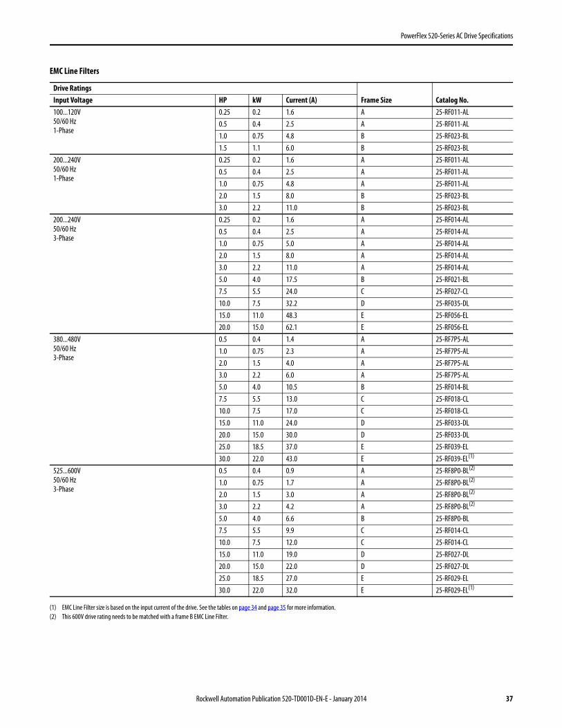
PowerFlex 520-Series AC Drive Specifications
(1) EMC Line Filter size is based on the input current of the drive. See the tables on page 34 and page 35 for more information.(2) This 600V drive rating needs to be matched with a frame B EMC Line Filter.
EMC Line Filters
Drive RatingsFrame Size Catalog No.Input Voltage HP kW Current (A)
100...120V50/60 Hz1-Phase
0.25 0.2 1.6 A 25-RF011-AL0.5 0.4 2.5 A 25-RF011-AL1.0 0.75 4.8 B 25-RF023-BL1.5 1.1 6.0 B 25-RF023-BL
200...240V50/60 Hz1-Phase
0.25 0.2 1.6 A 25-RF011-AL0.5 0.4 2.5 A 25-RF011-AL1.0 0.75 4.8 A 25-RF011-AL2.0 1.5 8.0 B 25-RF023-BL3.0 2.2 11.0 B 25-RF023-BL
200...240V50/60 Hz3-Phase
0.25 0.2 1.6 A 25-RF014-AL0.5 0.4 2.5 A 25-RF014-AL1.0 0.75 5.0 A 25-RF014-AL2.0 1.5 8.0 A 25-RF014-AL3.0 2.2 11.0 A 25-RF014-AL5.0 4.0 17.5 B 25-RF021-BL7.5 5.5 24.0 C 25-RF027-CL10.0 7.5 32.2 D 25-RF035-DL15.0 11.0 48.3 E 25-RF056-EL20.0 15.0 62.1 E 25-RF056-EL
380...480V50/60 Hz3-Phase
0.5 0.4 1.4 A 25-RF7P5-AL1.0 0.75 2.3 A 25-RF7P5-AL2.0 1.5 4.0 A 25-RF7P5-AL3.0 2.2 6.0 A 25-RF7P5-AL5.0 4.0 10.5 B 25-RF014-BL7.5 5.5 13.0 C 25-RF018-CL10.0 7.5 17.0 C 25-RF018-CL15.0 11.0 24.0 D 25-RF033-DL20.0 15.0 30.0 D 25-RF033-DL25.0 18.5 37.0 E 25-RF039-EL30.0 22.0 43.0 E 25-RF039-EL(1)
525...600V50/60 Hz3-Phase
0.5 0.4 0.9 A 25-RF8P0-BL(2)
1.0 0.75 1.7 A 25-RF8P0-BL(2)
2.0 1.5 3.0 A 25-RF8P0-BL(2)
3.0 2.2 4.2 A 25-RF8P0-BL(2)
5.0 4.0 6.6 B 25-RF8P0-BL7.5 5.5 9.9 C 25-RF014-CL10.0 7.5 12.0 C 25-RF014-CL15.0 11.0 19.0 D 25-RF027-DL20.0 15.0 22.0 D 25-RF027-DL25.0 18.5 27.0 E 25-RF029-EL30.0 22.0 32.0 E 25-RF029-EL(1)
Rockwell Automation Publication 520-TD001D-EN-E - January 2014 37
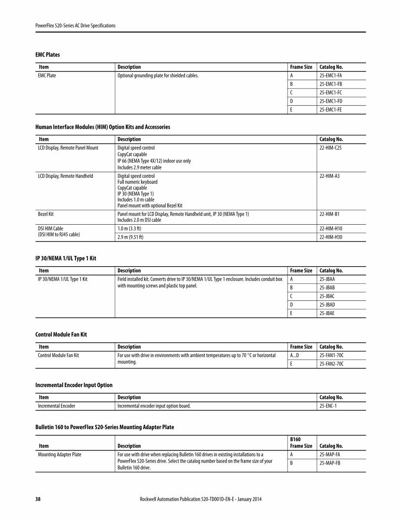
PowerFlex 520-Series AC Drive Specifications
EMC Plates
Item Description Frame Size Catalog No.EMC Plate Optional grounding plate for shielded cables. A 25-EMC1-FA
B 25-EMC1-FBC 25-EMC1-FCD 25-EMC1-FDE 25-EMC1-FE
Human Interface Modules (HIM) Option Kits and Accessories
Item Description Catalog No.LCD Display, Remote Panel Mount Digital speed control
CopyCat capableIP 66 (NEMA Type 4X/12) indoor use onlyIncludes 2.9 meter cable
22-HIM-C2S
LCD Display, Remote Handheld Digital speed controlFull numeric keyboardCopyCat capableIP 30 (NEMA Type 1)Includes 1.0 m cablePanel mount with optional Bezel Kit
22-HIM-A3
Bezel Kit Panel mount for LCD Display, Remote Handheld unit, IP 30 (NEMA Type 1)Includes 2.0 m DSI cable
22-HIM-B1
DSI HIM Cable(DSI HIM to RJ45 cable)
1.0 m (3.3 ft) 22-HIM-H102.9 m (9.51 ft) 22-HIM-H30
IP 30/NEMA 1/UL Type 1 Kit
Item Description Frame Size Catalog No.IP 30/NEMA 1/UL Type 1 Kit Field installed kit. Converts drive to IP 30/NEMA 1/UL Type 1 enclosure. Includes conduit box
with mounting screws and plastic top panel.A 25-JBAAB 25-JBABC 25-JBACD 25-JBADE 25-JBAE
Control Module Fan Kit
Item Description Frame Size Catalog No.Control Module Fan Kit For use with drive in environments with ambient temperatures up to 70 °C or horizontal
mounting.A...D 25-FAN1-70CE 25-FAN2-70C
Incremental Encoder Input Option
Item Description Catalog No.Incremental Encoder Incremental encoder input option board. 25-ENC-1
Bulletin 160 to PowerFlex 520-Series Mounting Adapter Plate
Item DescriptionB160Frame Size Catalog No.
Mounting Adapter Plate For use with drive when replacing Bulletin 160 drives in existing installations to a PowerFlex 520-Series drive. Select the catalog number based on the frame size of your Bulletin 160 drive.
A 25-MAP-FAB 25-MAP-FB
38 Rockwell Automation Publication 520-TD001D-EN-E - January 2014
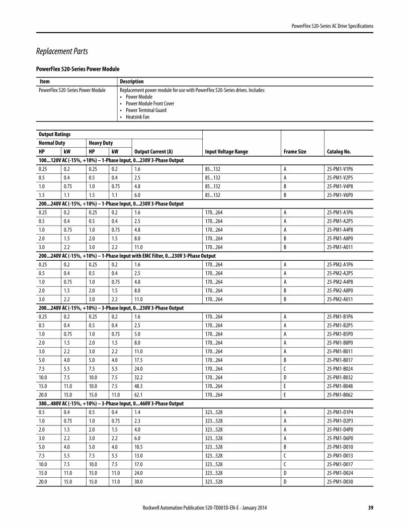
PowerFlex 520-Series AC Drive Specifications
Replacement Parts
PowerFlex 520-Series Power Module
Item DescriptionPowerFlex 520-Series Power Module Replacement power module for use with PowerFlex 520-Series drives. Includes:
• Power Module• Power Module Front Cover• Power Terminal Guard• Heatsink Fan
Output Ratings
Input Voltage Range Frame Size Catalog No.Normal Duty Heavy Duty
Output Current (A)HP kW HP kW100...120V AC (-15%, +10%) – 1-Phase Input, 0...230V 3-Phase Output 0.25 0.2 0.25 0.2 1.6 85...132 A 25-PM1-V1P60.5 0.4 0.5 0.4 2.5 85...132 A 25-PM1-V2P51.0 0.75 1.0 0.75 4.8 85...132 B 25-PM1-V4P81.5 1.1 1.5 1.1 6.0 85...132 B 25-PM1-V6P0200...240V AC (-15%, +10%) – 1-Phase Input, 0...230V 3-Phase Output0.25 0.2 0.25 0.2 1.6 170...264 A 25-PM1-A1P60.5 0.4 0.5 0.4 2.5 170...264 A 25-PM1-A2P51.0 0.75 1.0 0.75 4.8 170...264 A 25-PM1-A4P82.0 1.5 2.0 1.5 8.0 170...264 B 25-PM1-A8P03.0 2.2 3.0 2.2 11.0 170...264 B 25-PM1-A011200...240V AC (-15%, +10%) – 1-Phase Input with EMC Filter, 0...230V 3-Phase Output0.25 0.2 0.25 0.2 1.6 170...264 A 25-PM2-A1P60.5 0.4 0.5 0.4 2.5 170...264 A 25-PM2-A2P51.0 0.75 1.0 0.75 4.8 170...264 A 25-PM2-A4P82.0 1.5 2.0 1.5 8.0 170...264 B 25-PM2-A8P03.0 2.2 3.0 2.2 11.0 170...264 B 25-PM2-A011200...240V AC (-15%, +10%) – 3-Phase Input, 0...230V 3-Phase Output0.25 0.2 0.25 0.2 1.6 170...264 A 25-PM1-B1P60.5 0.4 0.5 0.4 2.5 170...264 A 25-PM1-B2P51.0 0.75 1.0 0.75 5.0 170...264 A 25-PM1-B5P02.0 1.5 2.0 1.5 8.0 170...264 A 25-PM1-B8P03.0 2.2 3.0 2.2 11.0 170...264 A 25-PM1-B0115.0 4.0 5.0 4.0 17.5 170...264 B 25-PM1-B0177.5 5.5 7.5 5.5 24.0 170...264 C 25-PM1-B02410.0 7.5 10.0 7.5 32.2 170...264 D 25-PM1-B03215.0 11.0 10.0 7.5 48.3 170...264 E 25-PM1-B04820.0 15.0 15.0 11.0 62.1 170...264 E 25-PM1-B062380...480V AC (-15%, +10%) – 3-Phase Input, 0...460V 3-Phase Output0.5 0.4 0.5 0.4 1.4 323...528 A 25-PM1-D1P41.0 0.75 1.0 0.75 2.3 323...528 A 25-PM1-D2P32.0 1.5 2.0 1.5 4.0 323...528 A 25-PM1-D4P03.0 2.2 3.0 2.2 6.0 323...528 A 25-PM1-D6P05.0 4.0 5.0 4.0 10.5 323...528 B 25-PM1-D0107.5 5.5 7.5 5.5 13.0 323...528 C 25-PM1-D01310.0 7.5 10.0 7.5 17.0 323...528 C 25-PM1-D01715.0 11.0 15.0 11.0 24.0 323...528 D 25-PM1-D02420.0 15.0 15.0 11.0 30.0 323...528 D 25-PM1-D030
Rockwell Automation Publication 520-TD001D-EN-E - January 2014 39
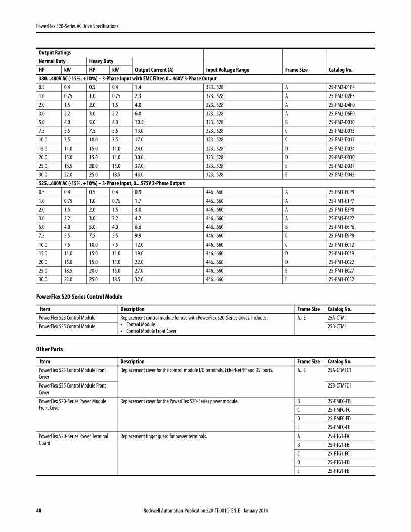
PowerFlex 520-Series AC Drive Specifications
380...480V AC (-15%, +10%) – 3-Phase Input with EMC Filter, 0...460V 3-Phase Output0.5 0.4 0.5 0.4 1.4 323...528 A 25-PM2-D1P41.0 0.75 1.0 0.75 2.3 323...528 A 25-PM2-D2P32.0 1.5 2.0 1.5 4.0 323...528 A 25-PM2-D4P03.0 2.2 3.0 2.2 6.0 323...528 A 25-PM2-D6P05.0 4.0 5.0 4.0 10.5 323...528 B 25-PM2-D0107.5 5.5 7.5 5.5 13.0 323...528 C 25-PM2-D01310.0 7.5 10.0 7.5 17.0 323...528 C 25-PM2-D01715.0 11.0 15.0 11.0 24.0 323...528 D 25-PM2-D02420.0 15.0 15.0 11.0 30.0 323...528 D 25-PM2-D03025.0 18.5 20.0 15.0 37.0 323...528 E 25-PM2-D03730.0 22.0 25.0 18.5 43.0 323...528 E 25-PM2-D043525...600V AC (-15%, +10%) – 3-Phase Input, 0...575V 3-Phase Output0.5 0.4 0.5 0.4 0.9 446...660 A 25-PM1-E0P91.0 0.75 1.0 0.75 1.7 446...660 A 25-PM1-E1P72.0 1.5 2.0 1.5 3.0 446...660 A 25-PM1-E3P03.0 2.2 3.0 2.2 4.2 446...660 A 25-PM1-E4P25.0 4.0 5.0 4.0 6.6 446...660 B 25-PM1-E6P67.5 5.5 7.5 5.5 9.9 446...660 C 25-PM1-E9P910.0 7.5 10.0 7.5 12.0 446...660 C 25-PM1-E01215.0 11.0 15.0 11.0 19.0 446...660 D 25-PM1-E01920.0 15.0 15.0 11.0 22.0 446...660 D 25-PM1-E02225.0 18.5 20.0 15.0 27.0 446...660 E 25-PM1-E02730.0 22.0 25.0 18.5 32.0 446...660 E 25-PM1-E032
PowerFlex 520-Series Control Module
Item Description Frame Size Catalog No.PowerFlex 523 Control Module Replacement control module for use with PowerFlex 520-Series drives. Includes:
• Control Module• Control Module Front Cover
A...E 25A-CTM1PowerFlex 525 Control Module 25B-CTM1
Other Parts
Item Description Frame Size Catalog No.PowerFlex 523 Control Module Front Cover
Replacement cover for the control module I/O terminals, EtherNet/IP and DSI ports. A...E 25A-CTMFC1
PowerFlex 525 Control Module Front Cover
25B-CTMFC1
PowerFlex 520-Series Power Module Front Cover
Replacement cover for the PowerFlex 520-Series power module. B 25-PMFC-FBC 25-PMFC-FCD 25-PMFC-FDE 25-PMFC-FE
PowerFlex 520-Series Power Terminal Guard
Replacement finger guard for power terminals. A 25-PTG1-FAB 25-PTG1-FBC 25-PTG1-FCD 25-PTG1-FDE 25-PTG1-FE
Output Ratings
Input Voltage Range Frame Size Catalog No.Normal Duty Heavy Duty
Output Current (A)HP kW HP kW
40 Rockwell Automation Publication 520-TD001D-EN-E - January 2014
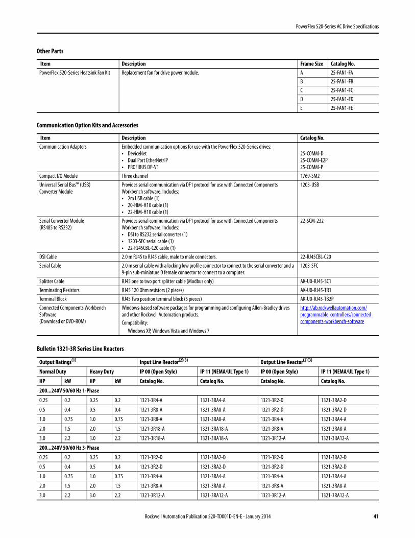
PowerFlex 520-Series AC Drive Specifications
PowerFlex 520-Series Heatsink Fan Kit Replacement fan for drive power module. A 25-FAN1-FAB 25-FAN1-FBC 25-FAN1-FCD 25-FAN1-FDE 25-FAN1-FE
Communication Option Kits and Accessories
Item Description Catalog No.Communication Adapters Embedded communication options for use with the PowerFlex 520-Series drives:
• DeviceNet• Dual Port EtherNet/IP• PROFIBUS DP-V1
25-COMM-D25-COMM-E2P25-COMM-P
Compact I/O Module Three channel 1769-SM2Universal Serial Bus™ (USB)Converter Module
Provides serial communication via DF1 protocol for use with Connected Components Workbench software. Includes:• 2m USB cable (1)• 20-HIM-H10 cable (1)• 22-HIM-H10 cable (1)
1203-USB
Serial Converter Module(RS485 to RS232)
Provides serial communication via DF1 protocol for use with Connected Components Workbench software. Includes:• DSI to RS232 serial converter (1)• 1203-SFC serial cable (1)• 22-RJ45CBL-C20 cable (1)
22-SCM-232
DSI Cable 2.0 m RJ45 to RJ45 cable, male to male connectors. 22-RJ45CBL-C20Serial Cable 2.0 m serial cable with a locking low profile connector to connect to the serial converter and a
9-pin sub-miniature D female connector to connect to a computer.1203-SFC
Splitter Cable RJ45 one to two port splitter cable (Modbus only) AK-U0-RJ45-SC1Terminating Resistors RJ45 120 Ohm resistors (2 pieces) AK-U0-RJ45-TR1Terminal Block RJ45 Two position terminal block (5 pieces) AK-U0-RJ45-TB2PConnected Components Workbench Software(Download or DVD-ROM)
Windows-based software packages for programming and configuring Allen-Bradley drives and other Rockwell Automation products.Compatibility:
Windows XP, Windows Vista and Windows 7
http://ab.rockwellautomation.com/programmable-controllers/connected-components-workbench-software
Bulletin 1321-3R Series Line Reactors
Output Ratings(1) Input Line Reactor(2)(3) Output Line Reactor(2)(3)
Normal Duty Heavy Duty IP 00 (Open Style) IP 11 (NEMA/UL Type 1) IP 00 (Open Style) IP 11 (NEMA/UL Type 1)
HP kW HP kW Catalog No. Catalog No. Catalog No. Catalog No.
200...240V 50/60 Hz 1-Phase
0.25 0.2 0.25 0.2 1321-3R4-A 1321-3RA4-A 1321-3R2-D 1321-3RA2-D
0.5 0.4 0.5 0.4 1321-3R8-A 1321-3RA8-A 1321-3R2-D 1321-3RA2-D
1.0 0.75 1.0 0.75 1321-3R8-A 1321-3RA8-A 1321-3R4-A 1321-3RA4-A
2.0 1.5 2.0 1.5 1321-3R18-A 1321-3RA18-A 1321-3R8-A 1321-3RA8-A
3.0 2.2 3.0 2.2 1321-3R18-A 1321-3RA18-A 1321-3R12-A 1321-3RA12-A
200...240V 50/60 Hz 3-Phase
0.25 0.2 0.25 0.2 1321-3R2-D 1321-3RA2-D 1321-3R2-D 1321-3RA2-D
0.5 0.4 0.5 0.4 1321-3R2-D 1321-3RA2-D 1321-3R2-D 1321-3RA2-D
1.0 0.75 1.0 0.75 1321-3R4-A 1321-3RA4-A 1321-3R4-A 1321-3RA4-A
2.0 1.5 2.0 1.5 1321-3R8-A 1321-3RA8-A 1321-3R8-A 1321-3RA8-A
3.0 2.2 3.0 2.2 1321-3R12-A 1321-3RA12-A 1321-3R12-A 1321-3RA12-A
Other Parts
Item Description Frame Size Catalog No.
Rockwell Automation Publication 520-TD001D-EN-E - January 2014 41
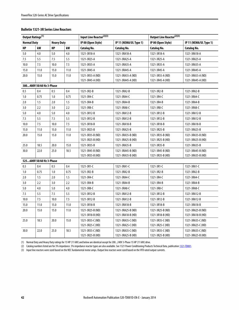
PowerFlex 520-Series AC Drive Specifications
(1) Normal Duty and Heavy Duty ratings for 15 HP (11 kW) and below are identical except for 200...240V 3-Phase 15 HP (11 kW) drive.(2) Catalog numbers listed are for 3% impedance. 5% impedance reactor types are also available. See 1321 Power Conditioning Products Technical Data, publication 1321-TD001.(3) Input line reactors were sized based on the NEC fundamental motor amps. Output line reactors were sized based on the VFD rated output currents.
5.0 4.0 5.0 4.0 1321-3R18-A 1321-3RA18-A 1321-3R18-A 1321-3RA18-A
7.5 5.5 7.5 5.5 1321-3R25-A 1321-3RA25-A 1321-3R25-A 1321-3RA25-A
10.0 7.5 10.0 7.5 1321-3R35-A 1321-3RA35-A 1321-3R35-A 1321-3RA35-A
15.0 11.0 15.0 11.0 1321-3R45-A 1321-3RA45-A 1321-3R45-A 1321-3RA45-A
20.0 15.0 15.0 11.0 1321-3R55-A (ND)1321-3R45-A (HD)
1321-3RA55-A (ND)1321-3RA45-A (HD)
1321-3R55-A (ND)1321-3R45-A (HD)
1321-3RA55-A (ND)1321-3RA45-A (HD)
380...480V 50/60 Hz 3-Phase
0.5 0.4 0.5 0.4 1321-3R2-B 1321-3RA2-B 1321-3R2-B 1321-3RA2-B
1.0 0.75 1.0 0.75 1321-3R4-C 1321-3RA4-C 1321-3R4-C 1321-3RA4-C
2.0 1.5 2.0 1.5 1321-3R4-B 1321-3RA4-B 1321-3R4-B 1321-3RA4-B
3.0 2.2 3.0 2.2 1321-3R8-C 1321-3RA8-C 1321-3R8-C 1321-3RA8-C
5.0 4.0 5.0 4.0 1321-3R12-B 1321-3RA12-B 1321-3R12-B 1321-3RA12-B
7.5 5.5 7.5 5.5 1321-3R12-B 1321-3RA12-B 1321-3R12-B 1321-3RA12-B
10.0 7.5 10.0 7.5 1321-3R18-B 1321-3RA18-B 1321-3R18-B 1321-3RA18-B
15.0 11.0 15.0 11.0 1321-3R25-B 1321-3RA25-B 1321-3R25-B 1321-3RA25-B
20.0 15.0 15.0 11.0 1321-3R35-B (ND)1321-3R25-B (HD)
1321-3RA35-B (ND)1321-3RA25-B (HD)
1321-3R35-B (ND)1321-3R25-B (HD)
1321-3RA35-B (ND)1321-3RA25-B (HD)
25.0 18.5 20.0 15.0 1321-3R35-B 1321-3RA35-B 1321-3R35-B 1321-3RA35-B
30.0 22.0 25.0 18.5 1321-3R45-B (ND)1321-3R35-B (HD)
1321-3RA45-B (ND)1321-3RA35-B (HD)
1321-3R45-B (ND)1321-3R35-B (HD)
1321-3RA45-B (ND)1321-3RA35-B (HD)
525...600V 50/60 Hz 3-Phase
0.5 0.4 0.5 0.4 1321-3R1-C 1321-3RA1-C 1321-3R1-C 1321-3RA1-C
1.0 0.75 1.0 0.75 1321-3R2-B 1321-3RA2-B 1321-3R2-B 1321-3RA2-B
2.0 1.5 2.0 1.5 1321-3R4-C 1321-3RA4-C 1321-3R4-C 1321-3RA4-C
3.0 2.2 3.0 2.2 1321-3R4-B 1321-3RA4-B 1321-3R4-B 1321-3RA4-B
5.0 4.0 5.0 4.0 1321-3R8-C 1321-3RA8-C 1321-3R8-C 1321-3RA8-C
7.5 5.5 7.5 5.5 1321-3R12-B 1321-3RA12-B 1321-3R12-B 1321-3RA12-B
10.0 7.5 10.0 7.5 1321-3R12-B 1321-3RA12-B 1321-3R12-B 1321-3RA12-B
15.0 11.0 15.0 11.0 1321-3R18-B 1321-3RA18-B 1321-3R18-B 1321-3RA18-B
20.0 15.0 15.0 11.0 1321-3R25-B (ND)1321-3R18-B (HD)
1321-3RA25-B (ND)1321-3RA18-B (HD)
1321-3R25-B (ND)1321-3R18-B (HD)
1321-3RA25-B (ND)1321-3RA18-B (HD)
25.0 18.5 20.0 15.0 1321-3R35-C (ND)1321-3R25-C (HD)
1321-3RA35-C (ND)1321-3RA25-C (HD)
1321-3R35-C (ND)1321-3R25-C (HD)
1321-3RA35-C (ND)1321-3RA25-C (HD)
30.0 22.0 25.0 18.5 1321-3R35-C (ND)1321-3R25-B (HD)
1321-3RA35-C (ND)1321-3RA25-B (HD)
1321-3R35-C (ND)1321-3R25-B (HD)
1321-3RA35-C (ND)1321-3RA25-B (HD)
Bulletin 1321-3R Series Line Reactors
Output Ratings(1) Input Line Reactor(2)(3) Output Line Reactor(2)(3)
Normal Duty Heavy Duty IP 00 (Open Style) IP 11 (NEMA/UL Type 1) IP 00 (Open Style) IP 11 (NEMA/UL Type 1)
HP kW HP kW Catalog No. Catalog No. Catalog No. Catalog No.
42 Rockwell Automation Publication 520-TD001D-EN-E - January 2014
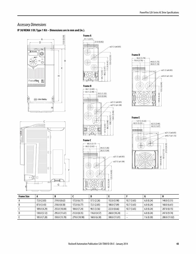
PowerFlex 520-Series AC Drive Specifications
Accessory DimensionsIP 30/NEMA 1/UL Type 1 Kit – Dimensions are in mm and (in.).
Frame Size A B C D E F G HA 72.0 (2.83) 219.0 (8.62) 172.0 (6.77) 57.5 (2.26) 152.0 (5.98) 92.7 (3.65) 6.0 (0.24) 140.0 (5.51)B 87.0 (3.43) 218.0 (8.58) 172.0 (6.77) 72.5 (2.85) 180.0 (7.09) 92.7 (3.65) 6.0 (0.24) 168.0 (6.61)C 109.0 (4.29) 255.0 (10.04) 184.0 (7.24) 90.5 (3.56) 222.0 (8.66) 92.7 (3.65) 6.0 (0.24) 207.0 (8.15)D 130.0 (5.12) 295.0 (11.61) 212.0 (8.35) 116.0 (4.57) 260.0 (10.24) – 6.0 (0.24) 247.0 (9.74)E 185.0 (7.28) 350.0 (13.78) 279.0 (10.98) 160.0 (6.30) 300.0 (11.81) – 7.6 (0.30) 280.0 (11.02)
C
F
G
Esc Sel
A
15.0
(0.5
9)
H
E
B
D51.1 (2.01)
21.0 (0.82)
135.
4 (5
.33)
111.
9 (4
.41)
88.2
(3.4
7)64
.7 (2
.55)
ø21.5 (ø0.85)
66.1 (2.60)63.1 (2.48)
33.5 (1.32)23.9 (0.94)
128.
5 (5
.06)
108.
5 (4
.27)
88.3
(3.4
8)67
.3 (2
.65)
ø21.5 (ø0.85)ø27.5 (ø1.08)
123.
3 (4
.85)
82.2
(3.2
4)
80.5 (3.17)66.5 (2.62)
34.5 (1.36)26.5 (1.04)
ø21.5 (ø0.85)
ø27.5 (ø1.08)10
9.8
(4.3
2)15
3.3
(6.0
4)
96.0 (3.78)
44.0 (1.73)30.0 (1.18)
70.0 (2.76)
ø21.5 (ø0.85)
ø33.5 (ø1.32)
127.5 (5.02)82.5 (3.25) 62.5 (2.46)
42.5 (1.67)
212.
0 (8
.35)
181.
0 (7
.13)
164.
0 (6
.46)
ø21.5 (ø0.85)ø43.7 (ø1.72)
Frame A
Frame B
Frame C
Frame D
Frame E
Rockwell Automation Publication 520-TD001D-EN-E - January 2014 43
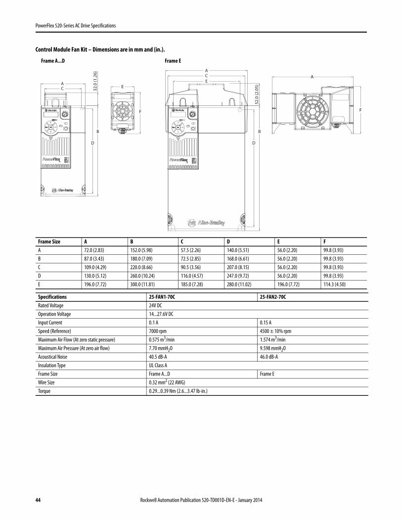
PowerFlex 520-Series AC Drive Specifications
Control Module Fan Kit – Dimensions are in mm and (in.).
Frame Size A B C D E FA 72.0 (2.83) 152.0 (5.98) 57.5 (2.26) 140.0 (5.51) 56.0 (2.20) 99.8 (3.93)B 87.0 (3.43) 180.0 (7.09) 72.5 (2.85) 168.0 (6.61) 56.0 (2.20) 99.8 (3.93)C 109.0 (4.29) 220.0 (8.66) 90.5 (3.56) 207.0 (8.15) 56.0 (2.20) 99.8 (3.93)D 130.0 (5.12) 260.0 (10.24) 116.0 (4.57) 247.0 (9.72) 56.0 (2.20) 99.8 (3.93)E 196.0 (7.72) 300.0 (11.81) 185.0 (7.28) 280.0 (11.02) 196.0 (7.72) 114.3 (4.50)
Specifications 25-FAN1-70C 25-FAN2-70CRated Voltage 24V DCOperation Voltage 14...27.6V DCInput Current 0.1 A 0.15 ASpeed (Reference) 7000 rpm 4500 ± 10% rpmMaximum Air Flow (At zero static pressure) 0.575 m3/min 1.574 m3/minMaximum Air Pressure (At zero air flow) 7.70 mmH2O 9.598 mmH2OAcoustical Noise 40.5 dB-A 46.0 dB-AInsulation Type UL Class AFrame Size Frame A...D Frame EWire Size 0.32 mm2 (22 AWG)Torque 0.29...0.39 Nm (2.6...3.47 lb-in.)
Esc Sel
A
32.0
(1.2
6)
B
D
C
Esc Sel
CA
52.0
(2.0
5)
B
D
EE
F
A
F
Frame A...D Frame E
44 Rockwell Automation Publication 520-TD001D-EN-E - January 2014
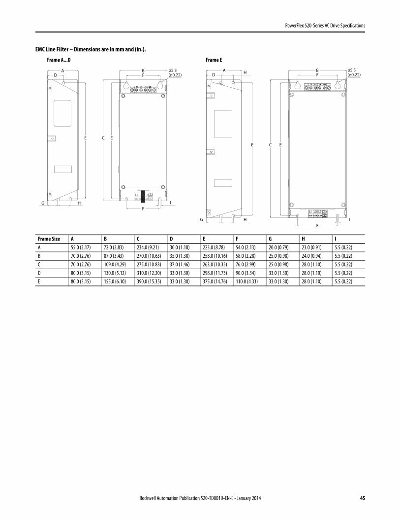
PowerFlex 520-Series AC Drive Specifications
EMC Line Filter – Dimensions are in mm and (in.).
Frame Size A B C D E F G H IA 55.0 (2.17) 72.0 (2.83) 234.0 (9.21) 30.0 (1.18) 223.0 (8.78) 54.0 (2.13) 20.0 (0.79) 23.0 (0.91) 5.5 (0.22)B 70.0 (2.76) 87.0 (3.43) 270.0 (10.63) 35.0 (1.38) 258.0 (10.16) 58.0 (2.28) 25.0 (0.98) 24.0 (0.94) 5.5 (0.22)C 70.0 (2.76) 109.0 (4.29) 275.0 (10.83) 37.0 (1.46) 263.0 (10.35) 76.0 (2.99) 25.0 (0.98) 28.0 (1.10) 5.5 (0.22)D 80.0 (3.15) 130.0 (5.12) 310.0 (12.20) 33.0 (1.30) 298.0 (11.73) 90.0 (3.54) 33.0 (1.30) 28.0 (1.10) 5.5 (0.22)E 80.0 (3.15) 155.0 (6.10) 390.0 (15.35) 33.0 (1.30) 375.0 (14.76) 110.0 (4.33) 33.0 (1.30) 28.0 (1.10) 5.5 (0.22)
AD
E
G H
AD
E
G H
H BF
F
C E
I
ø5.5(ø0.22)
B
C E
F
FI
ø5.5(ø0.22)
BLACK BLACK
L1 L2 L3BLACK YELLOW
&GREEN
Frame A...D Frame E
Rockwell Automation Publication 520-TD001D-EN-E - January 2014 45
PowerFlex 520-Series AC Drive Specifications
Safe-Torque-Off Function
The PowerFlex 525 Safe-Torque-Off function, when used with other safety components, helps provide protection according to EN ISO 13849 and EN62061 for safe-off and protection against restart. The PowerFlex 525 Safe-Torque-Off function is just one component in a safety control system. Components in the system must be chosen and applied appropriately to achieve the desired level of operator safeguarding.
PowerFlex 525 Safe-Torque-Off Overview
The PowerFlex 525 Safe-Torque-Off function:• Provides the Safe-Torque-Off (STO) function defined in EN IEC 61800-5-2.• Blocks gate-firing signals from reaching the Insulated Gate Bipolar Transistor (IGBT) output devices of the drive.
This prevents the IGBTs from switching in the sequence necessary to generate torque in the motor.• Can be used in combination with other safety devices to fulfill the requirements of a system “safe torque off ”
function which satisfies Category 3 / PL (d) according to EN ISO 13849-1 and SIL CL2 according to EN/IEC 62061, IEC 61508, and EN/IEC 61800-5-2.
EC Type Examination Certification
TÜV Rheinland has certified the PowerFlex 525 Safe-Torque-Off function compliant with the requirements for machines defined in Annex I of the EC Directive 2006/42/EC, and that it complies with the requirements of the relevant standards listed below:
• EN ISO 13849-1:2008 Safety of machinery – Safety related parts of control systems – Part 1: General principles for design. (PowerFlex 525 STO achieves Category 3 / PL(d))
• EN 61800-5-2:2007 Adjustable speed electrical power drive systems – Part 5-2 Safety requirements – Functional. (PowerFlex 525 STO achieves SIL CL 2)
• EN 62061:2005 Safety of machinery – Functional safety of safety-related electrical, electronic and programmable electronic control systems.
• IEC 61508 Part 1-7:2010 Functional safety of electrical/electronic/programmable electronic safety-related systems – Parts 1-7.
TÜV also certifies that the PowerFlex 525 STO may be used in applications up to Category 3/ PL(d) according to EN ISO 13849-1 and SIL 2 according to EN 62061 / EN 61800-5-2 / IEC 61508.
The TÜV Rheinland certificate may be found at http://www.rockwellautomation.com/products/certification/.
Safety Concept
The PowerFlex 525 Safe-Torque-Off function is suitable for use in safety applications up to and including Category 3 / PL(d) according to EN ISO 13849-1 and SIL 2 according to EN 62061 / EN 61800-5-2 / IEC 61508.
In addition, the PowerFlex 525 STO function may be used together with other components in a safety application to achieve an overall Category 3 / PL(e) according to EN ISO 13849-1 and SIL 3 according to EN 62061 and IEC 61508. This is illustrated in Example 3 on page 50.
Safety requirements are based on the standards current at the time of certification.
46 Rockwell Automation Publication 520-TD001D-EN-E - January 2014
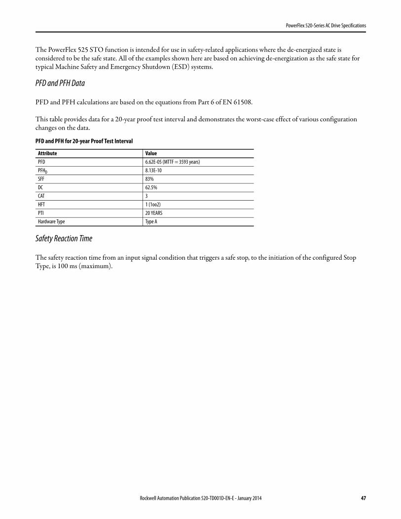
PowerFlex 520-Series AC Drive Specifications
The PowerFlex 525 STO function is intended for use in safety-related applications where the de-energized state is considered to be the safe state. All of the examples shown here are based on achieving de-energization as the safe state for typical Machine Safety and Emergency Shutdown (ESD) systems.
PFD and PFH Data
PFD and PFH calculations are based on the equations from Part 6 of EN 61508.
This table provides data for a 20-year proof test interval and demonstrates the worst-case effect of various configuration changes on the data.
Safety Reaction Time
The safety reaction time from an input signal condition that triggers a safe stop, to the initiation of the configured Stop Type, is 100 ms (maximum).
PFD and PFH for 20-year Proof Test Interval
Attribute ValuePFD 6.62E-05 (MTTF = 3593 years)PFHD 8.13E-10SFF 83%DC 62.5%CAT 3HFT 1 (1oo2)PTI 20 YEARSHardware Type Type A
Rockwell Automation Publication 520-TD001D-EN-E - January 2014 47
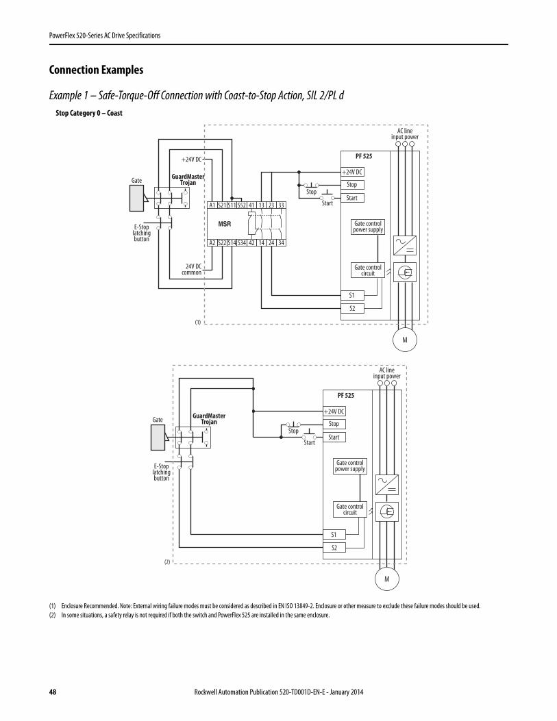
PowerFlex 520-Series AC Drive Specifications
Connection Examples
Example 1 – Safe-Torque-Off Connection with Coast-to-Stop Action, SIL 2/PL d
(1) Enclosure Recommended. Note: External wiring failure modes must be considered as described in EN ISO 13849-2. Enclosure or other measure to exclude these failure modes should be used.(2) In some situations, a safety relay is not required if both the switch and PowerFlex 525 are installed in the same enclosure.
Stop
StartA1 S21 S11 S52 41 13 23 33
A2
24V DCcommon
+24V DC
S22 S14 S34 42 14 24 34
MSR
GuardMasterTrojanGate
E-Stoplatchingbutton
+24V DC
PF 525
Stop
Start
Gate controlpower supply
Gate controlcircuit
AC lineinput power
S1
S2
M
(1)
Stop
Start
GuardMasterTrojanGate
E-Stoplatchingbutton
+24V DC
PF 525
Stop
Start
Gate controlpower supply
Gate controlcircuit
AC lineinput power
S1
S2
M
(2)
Stop Category 0 – Coast
48 Rockwell Automation Publication 520-TD001D-EN-E - January 2014
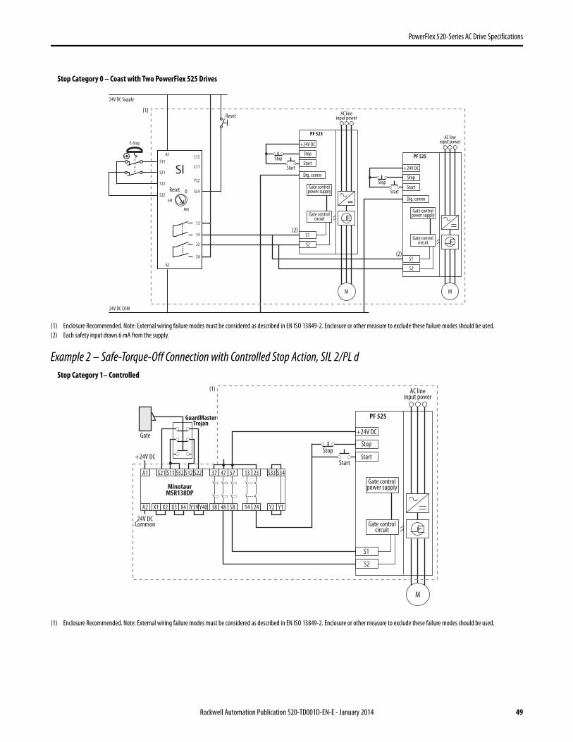
PowerFlex 520-Series AC Drive Specifications
(1) Enclosure Recommended. Note: External wiring failure modes must be considered as described in EN ISO 13849-2. Enclosure or other measure to exclude these failure modes should be used.(2) Each safety input draws 6 mA from the supply.
Example 2 – Safe-Torque-Off Connection with Controlled Stop Action, SIL 2/PL d
(1) Enclosure Recommended. Note: External wiring failure modes must be considered as described in EN ISO 13849-2. Enclosure or other measure to exclude these failure modes should be used.
Stop
Start
+24V DC
PF 525
Stop
Start
Dig. comm
Gate controlpower supply
Gate controlcircuit
AC lineinput power
S1
S2
M
Stop
Start
+24V DC
PF 525
Stop
Start
Dig. comm
Gate controlpower supply
Gate controlcircuit
AC lineinput power
S1
S2
M
(1)
(2)
(2)
S11
S21
S12
S22
13
14
23
24
L11
A1
S34
L12
A2
SI
24V DC Supply
24V DC COM
E-Stop
Y32
0
AM
MM
Reset
Reset
Stop Category 0 – Coast with Two PowerFlex 525 Drives
24V DCCommon
+24V DC
GuardMasterTrojan
Stop
StartA1 S21 S11 S52 S12
A2 X1 X2
13 23
14 24
S33
Y2
S34
Y1X3
37 47 57
38 48 58X4
S22
Y39 Y40
MinotaurMSR138DP
Gate +24V DC
PF 525
Stop
Start
Gate controlpower supply
Gate controlcircuit
AC lineinput power
S1
S2
M
(1)
Stop Category 1– Controlled
Rockwell Automation Publication 520-TD001D-EN-E - January 2014 49
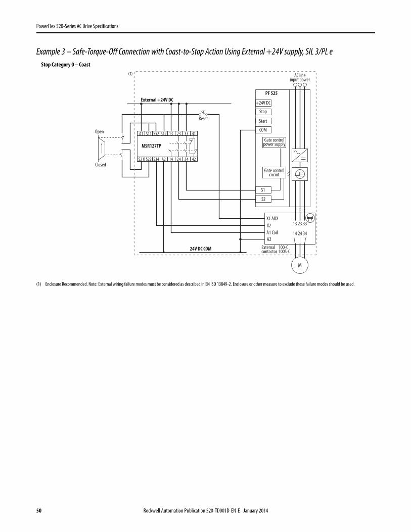
PowerFlex 520-Series AC Drive Specifications
Example 3 – Safe-Torque-Off Connection with Coast-to-Stop Action Using External +24V supply, SIL 3/PL e
(1) Enclosure Recommended. Note: External wiring failure modes must be considered as described in EN ISO 13849-2. Enclosure or other measure to exclude these failure modes should be used.
Closed
Open
External +24V DC
24V DC COM
MSR127TP
Reset
+24V DC
PF 525
Stop
Start
COM
Gate controlpower supply
Gate controlcircuit
AC lineinput power
S1
S2
X1 AUXX2A1 CoilA2
Externalcontactor
100-C100S-C
13 23 33
14 24 34
M
A1 S11 S52 S12 13 23 33 41
S21 S22 S34 A2 14 24 34 42
(1)
Stop Category 0 – Coast
50 Rockwell Automation Publication 520-TD001D-EN-E - January 2014

PowerFlex 520-Series AC Drive Specifications
Additional Resources
These documents contain additional information concerning related products from Rockwell Automation.
You can view or download publications at http://www.rockwellautomation.com/literature/. To order paper copies of technical documentation, contact your local Allen-Bradley distributor or Rockwell Automation sales representative.
Title PublicationPowerFlex 520-Series Adjustable Frequency AC Drive User Manual 520-UM001 PowerFlex 4-Class Human Interface Module (HIM) DSI Quick Reference 22HIM-QR001 PowerFlex 525 Embedded EtherNet/IP Adapter User Manual 520COM-UM001 PowerFlex 25-COMM-D DeviceNet Adapter User Manual 520COM-UM002 PowerFlex 25-COMM-E2P EtherNet/IP Adapter User Manual 520COM-UM003 PowerFlex 25-COMM-P PROFIBUS DP Adapter User Manual 520COM-UM004 Dynamic Braking Resistor Calculator PFLEX-AT001 Wiring and Grounding Guidelines for PWM AC Drives DRIVES-IN001 Preventive Maintenance of Industrial Control and Drive System Equipment DRIVES-TD001 Safety Guidelines for the Application, Installation and Maintenance of Solid State Control SGI-1.1
Rockwell Automation Publication 520-TD001D-EN-E - January 2014 51

Allen-Bradley, Rockwell Software, Rockwell Automation, PowerFlex, Connected Components Workbench, Studio 5000, DriveTools SP, AppView, CustomView, MainsFree Programming, and P ointStop are trademarks of Rockwell Automation, Inc.
Trademarks not belonging to Rockwell Automation are property of their respective companies.
Publication 520-TD001D-EN-E - January 2014 Supersedes Publication 520-TD001C-EN-E – September 2013 Copyright © 2014 Rockwell Automation, Inc. All rights reserved.
Power, Control and Information Solutions HeadquartersAmericas: Rockwell Automation, 1201 South Second Street, Milwaukee, WI 53204-2496 USA, Tel: (1) 414.382.2000, Fax: (1) 414.382.4444Europe/Middle East/Africa: Rockwell Automation NV, Pegasus Park, De Kleetlaan 12a, 1831 Diegem, Belgium, Tel: (32) 2 663 0600, Fax: (32) 2 663 0640Asia Pacific: Rockwell Automation, Level 14, Core F, Cyberport 3, 100 Cyberport Road, Hong Kong, Tel: (852) 2887 4788, Fax: (852) 2508 1846
www.rockwel lautomation.com
Important Information
Solid-state equipment has operational characteristics differing from those of electromechanical equipment. Safety Guidelines for the Application, Installation and Maintenance of Solid State Controls (publication SGI-1.1 available from your local Rockwell Automation sales office or online at http://www.rockwellautomation.com/literature/) describes some important differences between solid-state equipment and hard-wired electromechanical devices. Because of this difference, and also because of the wide variety of uses for solid-state equipment, all persons responsible for applying this equipment must satisfy themselves that each intended application of this equipment is acceptable.
In no event will Rockwell Automation, Inc. be responsible or liable for indirect or consequential damages resulting from the use or application of this equipment.
The examples and diagrams in this publication are included solely for illustrative purposes. Because of the many variables and requirements associated with any particular installation, Rockwell Automation, Inc. cannot assume responsibility or liability for actual use based on the examples and diagrams.
No patent liability is assumed by Rockwell Automation, Inc. with respect to use of information, circuits, equipment, or software described in this manual.
Reproduction of the contents of this manual, in whole or in part, without written permission of Rockwell Automation, Inc., is prohibited.
Documentation Feedback
Your comments will help us serve your documentation needs better. If you have any suggestions on how to improve this document, complete this form, publication RA-DU002, available at http://www.rockwellautomation.com/literature/.