Embed Size (px)
Citation preview

Instruction ManualPORTABLEpH/ORP/DISSOLVED OXYGEN METERD-75
Preface
Part names and basic operation
Measurement
Maintenance
How to resolve errors or troubles
Appendix
Usinig various functions

I
PrefaceThis manual describes the operation of the Portable pH/ORP/Dissolved Oxygen Meter D-75.Be sure to read this manual before using the product to ensure proper and safe operation of the product. Also safely store the manual so it is readily available whenever necessary.Product specifications and appearance, as well as the contents of this manual are subject to change without notice.
■ Warranty and responsibilityHORIBA, Ltd. warrants that the Product shall be free from defects in material and workmanship and agrees to repair or replace free of charge, at option of HORIBA, Ltd., any malfunctioned or damaged Product attributable to responsibility of HORIBA, Ltd. for a period of one (1) year from the delivery unless otherwise agreed with a written agreement. In any one of the following cases, none of the warranties set forth herein shall be extended;
・ Any malfunction or damage attributable to improper operation・ Any malfunction attributable to repair or modification by any person not authorized
by HORIBA, Ltd.・ Any malfunction or damage attributable to the use in an environment not specified in
this manual・ Any malfunction or damage attributable to violation of the instructions in this manual
or operations in the manner not specified in this manual・ Any malfunction or damage attributable to any cause or causes beyond the
reasonable control of HORIBA, Ltd. such as natural disasters・ Any deterioration in appearance attributable to corrosion, rust, and so on・ Replacement of consumables
HORIBA, LTD. SHALL NOT BE LIABLE FOR ANY DAMAGES RESULTING FROM ANY MALFUNCTIONS OF THE PRODUCT, ANY ERASURE OF DATA, OR ANY OTHER USES OF THE PRODUCT.
■ Trademarks・ Microsoft, Windows, Windows Vista are registered trademarks or trademarks of
Microsoft Corporation in the United States and other countries.Other company names and brand names are either registered trademarks or trademarks of the respective companies. (R), (TM) symbols may be omitted in this manual.
CODE:I20033950003200520070GZ0000333610 August, 2013 2013 HORIBA, Ltd.

Check items
II
■ Items in packageAfter opening the package, check for damage on the instrument and that the standard accessories (see below) all exist.If damage or defects are found on the product, contact your dealer.
Note
・ The accessories are not waterproof.・ The supplied alkaline batteries are used to check operation, thus it is possible that the
battery will be run out quickly.
Instrument Instruction manual(this book)
Quick-start Manual AAA alkaline batteries

Regulations
III
■ Conformable DirectiveThis equipment conforms to the following directives and standards:
●Installation EnvironmentThis product is designed for the following environment. ・Overvoltage Category II ・Pollution degree 2
WARNING: Do not use the equipment for measurements within measurement categories II, III and IV.
●Information on disposal of electrical and electronic equipment and disposal of batteries and accumulatorsThe crossed out wheeled bin symbol with underbar shown on the product or accompanying documents indicates the product requires appropriate treatment, collection and recycle for waste electrical and electronic equipment (WEEE) under the Directive 2002/96/EC, and/or waste batteries and accumulators under the Directive 2006/66/EC in the European Union. The symbol might be put with one of the chemical symbols below. In this case, it satisfies the requirements of the Directive 2006/66/EC for the object chemical. This product should not be disposed of as unsorted household waste.Your correct disposal of WEEE, waste batteries and accumulators will contribute to reducing wasteful consumption of natural resources, and protecting human health and the environment from potential negative effects caused by hazardous substance in products.Contact your supplier for information on applicable disposal methods.
Directives: The EMC Directive 2004/108/ECThe Low Voltage Directive 2006/95/ECThe RoHS Directive 2011/65/EU
Standards: [the EMC Directive] EN61326-1:2006Class B, Basic requirements[the Low Voltage Directive] EN61010-1:2010(Ed.3.0)[the RoHS Directive] EN50581:2012Category: 9. Monitoring and control instruments
Regulations
IV
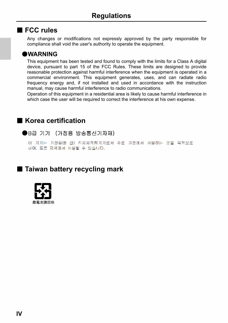
■ FCC rulesAny changes or modifications not expressly approved by the party responsible for compliance shall void the user's authority to operate the equipment.
●WARNINGThis equipment has been tested and found to comply with the limits for a Class A digital device, pursuant to part 15 of the FCC Rules. These limits are designed to provide reasonable protection against harmful interference when the equipment is operated in a commercial environment. This equipment generates, uses, and can radiate radio frequency energy and, if not installed and used in accordance with the instruction manual, may cause harmful interference to radio communications. Operation of this equipment in a residential area is likely to cause harmful interference in which case the user will be required to correct the interference at his own expense.
■ Korea certification
●
■ Taiwan battery recycling mark
For your safety
V
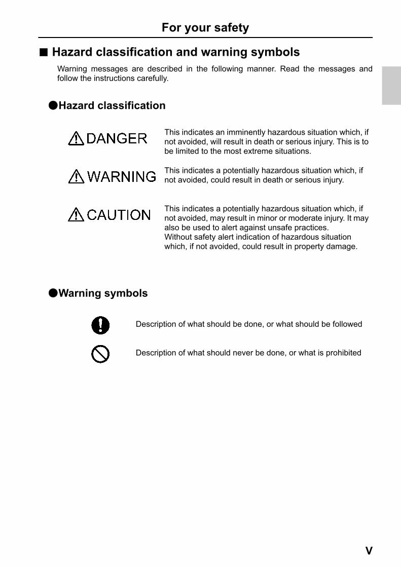
■ Hazard classification and warning symbolsWarning messages are described in the following manner. Read the messages and follow the instructions carefully.
●Hazard classification
●Warning symbols
This indicates an imminently hazardous situation which, if not avoided, will result in death or serious injury. This is to be limited to the most extreme situations.
This indicates a potentially hazardous situation which, if not avoided, could result in death or serious injury.
This indicates a potentially hazardous situation which, if not avoided, may result in minor or moderate injury. It may also be used to alert against unsafe practices.Without safety alert indication of hazardous situation which, if not avoided, could result in property damage.
Description of what should be done, or what should be followed
Description of what should never be done, or what is prohibited

For your safety
VI
■ Safety precautionsThis section provides precautions for using the product safely and correctly and to prevent injury and damage. The terms of DANGER, WARNING, and CAUTION indicate the degree of imminency and hazardous situation. Read the precautions carefully as it contains important safety messages.
●Instrument and electrode
WARNING
Do not use an unspecified AC adapter.Otherwise, it may heat up or be ignited resulting in a fire or an accident.
Do not disassemble or modify the instrument.Otherwise, it may heat up or be ignited resulting in a fire or an accident.
CAUTION
Harmful chemicalsThe internal solution of DO electrodes is highly potassium hydroxide (KOH). If it gets into eyes, flush with plenty of water and then consult a doctor. If it gets into eyes, flush with plenty of water and then consult a doctor.
Harmful chemicalsThe internal solution of pH electrode is highly concentrated potassium chloride (3.33 mol/L KCl). If the internal solution comes in contact with the skin, wash it off immediately. If it gets into the eyes, flush with plenty of water and then consult a doctor.
Broken glassBroken glass may cause injury. The outer tube and tip of an electrode are made of glass. Handle them with care.
Do not use the RS-232C communication and the AC adapter under wet or humid conditions. Otherwise, it may cause a fire, electric shock, or breakage.

For your safety
VII
●Battery
WARNING
Keep batteries out of reach of children. If someone accidentally swallows a battery, consult a doctor immediately.
If alkaline fluid from a battery gets into the eyes, do not rub the eyes, rinse with clean water immediately and then consult a doctor.Contact with alkaline fluid could cause blindness.
Do not put batteries in a fire, expose to heat, disassemble or remodel.Doing so could case fluid leakage, overheating or explosion.
CAUTION
Do not remove or scratch the external label of the battery.Doing so could cause injury to hands and fingers.

For your safety
VIII
■ Product handling information
●Operational precautions (instrument) ・The function that measuring dissolved oxygen of the instrument is only usable for
measuring under water. Do not use this function for the application except described above.
・Do not drop, crash, or give any physical impact on the instrument.
・The instrument is made of solvent-resistant materials but that does not mean it is resistant to all chemicals. Do not dip the instrument in strong acid or alkali solution, or wipe with such solution.
・If the instrument is dropped into water or gets wet, wipe it using soft cloth. Do not heat to dry it with a hair-dryer (or the like).
・The instrument has a dust-proof and waterproof structure. Waterproof performance is following specification: the instrument does not malfunction even when immersed in water of 1 m depth for 30 minutes. This does not mean to guarantee non-destructive, trouble-free, dust-proof, and waterproof performance in all situations. If the instrument is correctly handled according to the descriptions in this manual, the instrument provides dust-proof and waterproof performance.
・When replacing the batteries, while connected to the AC adapter, or during the RS- 232C communication, the instrument does not have the dust-proof and waterproof performance. The dust-proof and waterproof performance is maintained only when the covers are attached correctly.
・After replacing the batteries, connecting the AC adapter, and using the RS-232C communication, make sure that the waterproof packing attached to each cover is not deformed or discolored, or has foreign matter adhering to it. If the waterproof packing is deformed, discolored or has foreign matter adhering to it, or dust could get inside, water leaks could occur that could lead to instrument malfunction.
・To disconnect an electrode or AC adapter cable or serial cable, hold the connector and pull it off. If you pull at the cable, it may cause a breakage.
・The RS-232C communication between the instrument and a personal computer (PC) may fail because of environmental conditions, such as (radio/electromagnetic) noise.
・Do not replace the batteries, connect the AC adapter, or use the RS-232C communication in a dusty place or with wet hands. Dust or moisture could get inside the instrument, possibly causing instrument malfunction.
・Do not use the tip of a nail or an object with a sharp end to press the keys.
・If the power supply is interrupted while measurement data is being saved in the instrument, the data could be corrupted.

For your safety
IX
・A NiMH rechargeable battery can be used in this instrument, but the battery used in the instrument cannot be charged using the AC adapter.
●Operational precautions (battery) ・Do not short circuit a battery.
・Set the + and side of the battery correctly.
・When the battery has run out or the instrument will not be used for a long time, remove the batteries.
・Of the specified battery types, make sure to use two batteries of the same type.
・Do not use a new battery together with a used battery.
・Do not use a fully charged nickel-metal hydride battery together with a partially charged battery.
・Do not attempt to charge a non-rechargeable battery.
●Environmental conditions for use and storage ・Temperature: 0°C to 45°C ・Humidity: under 80% in relative humidity and free from condensation
Avoid the following conditions. ・Strong vibration ・Direct sunlight ・Corrosive gas environment ・Close to an air-conditioner ・Direct wind
●TransportationWhen transporting the instrument, repackage it in the original package box. Otherwise, it may cause instrument breakage.
●Disposal ・Standard solution used for the calibration must be under neutralized before the
disposal.
・When disposing of the product, follow the related laws and/or regulations of your country for disposal of the product.

For your safety
X
■ Manual information
●Description in this manual
This interprets the necessary points for correct operation and notifies the important points for handling the product.
This indicates the part where to refer for information.
This indicates reference information.
Note
Reference
Tip
Contents
XI
Preface ................................................................................... I
■ Items in package.................................................................. II
■ Hazard classification and warning symbols .................... V
■ Safety precautions ............................................................ VI
■ Product handling information ........................................ VIII
■ Manual information ............................................................ X
Part names and basic operation......................................... 1
■ Names of each part .............................................................2
● Instrument....................................................................................2
● Display .........................................................................................3
● Operation key ..............................................................................5
■ Basic operation....................................................................6
● Changing the operation mode ...................................................6
● Switching the displays ...............................................................7
● Changing the measurement parameter ....................................8
● Using the backlight .....................................................................9
● Entering numeric values ..........................................................10
Measurement ...................................................................... 11
■ Preparation.........................................................................12
● Confirmation before starting measurement ...........................12
● Turning ON the instrument ......................................................13
● Setting the date and time .........................................................15
● Connecting an electrode ..........................................................16
■ pH measurement ...............................................................17
● Setting the instrument ..............................................................17
● Performing calibration..............................................................20
● Performing measurement.........................................................27

Contents
XII
■ mV, ORP measurement .....................................................28
● Setting the instrument.............................................................. 28
● Switching between absolute value and relative value .......... 29
● Performing measurement ........................................................ 30
■ Dissolved oxygen measurement......................................31
● Setting the instrument.............................................................. 31
● Performing calibration ............................................................. 35
● Performing measurement ........................................................ 40
Using various functions .................................................... 43
● Saving measurement data in the internal memory................ 44
● Displaying saved data .............................................................. 45
● Deleting all saved data ............................................................. 46
● Displaying the latest calibration and inspection data........... 47
● Deleting calibration data .......................................................... 49
● Printing measured values and calibration data ..................... 50
● Transferring saved data to a PC.............................................. 56
● Operating the instrument from an external device................ 57
● Using the automatic data save (default: OFF) ....................... 58
● Setting the ID number (default: 000) ....................................... 60
● Using the calibration interval alarm (default: OFF) ............... 61
● Calibrating temperature sensor .............................................. 62
● Changing the automatic power off setting (default: OFF) ....63
● Performing test printing of the printer unit ............................ 64
● Resetting to factory default settings ...................................... 65
Maintenance ....................................................................... 67
● Maintenance and storage of the instrument .......................... 67
● Environmental conditions for storage.................................... 67
● Maintenance and storage of the pH electrode ....................... 68
● Maintenance and storage of the ORP electrode .................... 69

Contents
XIII
● Checking the state of the ORP electrode................................70
● Maintenance and storage of the DO electrode.......................71
How to resolve errors or troubles .................................... 73
■ When an error message appears .....................................73
● ERR No.0001 Memory error ...................................................73
● ERR No.0002 Empty battery level .........................................74
● ERR No.0003 Electrode stability error..................................74
● ERR No.0004 Asymmetric potential error ............................74
● ERR No.0005 Electrode sensitivity error (pH)......................75
● ERR No.0005 Electrode sensitivity error (DO) .....................75
● ERR No.0006 Maximum calibration points exceeded .........76
● ERR No.0007 Cannot identify standard solution.................76
● ERR No.0008 Calibration interval error ................................76
● ERR No.0009 Printer error .....................................................77
● ERR No.0010 Memory full ......................................................77
■ Troubleshooting ................................................................78
● The indicated value fluctuates.................................................78
● The response is slow................................................................79
● The indicated value does not change/No response ..............79
● The measured value blinks ......................................................80
● The temperature display blinks or is fixed at 25°C................80
● Repeatability of the measured value is poor..........................81
● Nothing appears when the power is turned ON.....................81
● Swelling of operation key sheet ..............................................81
● Part of the display is missing ..................................................82
Appendix............................................................................. 83
■ Main specifications ...........................................................83
■ Instrument default settings ..............................................84

Contents
XIV
■ Technical note....................................................................85
● pH measurement (glass electrode) ......................................... 85
● pH standard solutions at various temperatures .................... 86
● ORP measurement.................................................................... 87
● Dissolved oxygen measurement............................................. 88
● Salinity concentration correction............................................ 89
● Air pressure correction ............................................................ 89
● Saturated DO levels in water at various temperatures ......... 90
■ For more information ........................................................91
■ Options ...............................................................................92
D-75 1
Part names and basic operationThis section describes the name of each part and the main role, function, and basic operation method of each part.
■ Names of each part...................................................................... 2
● Instrument.............................................................................................. 2
● Display.................................................................................................... 3• Battery level display .............................................................................................. 4
● Operation key ........................................................................................ 5
■ Basic operation............................................................................ 6
● Changing the operation mode ............................................................. 6
● Switching the displays.......................................................................... 7
● Changing the measurement parameter............................................... 8
● Using the backlight ............................................................................... 9
● Entering numeric values..................................................................... 10

Names of each part
2 HORIBA
■ Names of each part
● Instrument
No. Name Function
1 Display Displays the measured value and set value and so on.
2 Operation keys Used for instrument operation.
3 Electrode connector Connects the BNC connector of the electrode.
4 Temperature connector Connects the temperature connector of the electrode.
5 Battery cover Set batteries inside.
6Electrode hook
attachment sectionAttach the electrode hook to carry with instrument.
7 Strap attachment section Attach a strap.
8 Serial connector Connects the serial cable and printer cable.
9 AC power connector Connects an optional AC adapter.

Names of each part
D-75 3
● DisplayTwo electrodes can be connected to measure two parameters at the same time with this instrument. The display is divided into the main screen and the sub screen, and you can select the channel displayed on the main screen. The selected channel can be identified with an icon.
No. Name Function
1 Status iconDisplays the current operation mode, electrode status, printer or PC connection status, and remaining battery level.
2 Direction key icon Displays the currently available direction key.
3Date and time, set item
display areaDisplays the current date and time and the set items.
4 ERR No. icon Displays an error No.
5 Data No. icon Displays the data No.
6Measurement parameter
display area
Displays the currently set measurement parameter.This is displayed in the main screen and the sub screen, respectively.
7 Main screen channel icon Displays the channel of the main screen.
8 HOLD iconLights when the measured value display is fixed.This is displayed in the main screen and the sub screen, respectively.
9 SET icon Lights when numerical values are entered.
10 Temperature display areaDisplays the measured and the set temperature.This is displayed in the main screen and the sub screen, respectively.
11 MTC icon
Lights when the temperature setting is MTC (optional temperature setting).This is displayed in the main screen and the sub screen, respectively.
12Measured value, set item
display area
Displays the measured value and the set value.This is displayed in the main screen and the sub screen, respectively.
12
45 6
89
2
13 14
2
311
10
12
7
6
812 14
11 10
Main screen
Sub screen
Names of each part
4 HORIBA
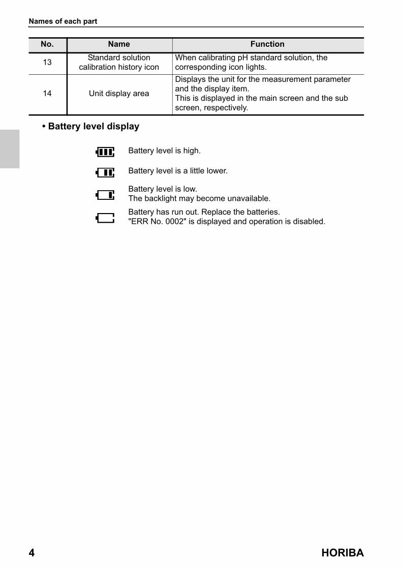
• Battery level display
13Standard solution
calibration history iconWhen calibrating pH standard solution, the corresponding icon lights.
14 Unit display area
Displays the unit for the measurement parameter and the display item.This is displayed in the main screen and the sub screen, respectively.
No. Name Function
Battery level is high.
Battery level is a little lower.
Battery level is low.The backlight may become unavailable.
Battery has run out. Replace the batteries."ERR No. 0002" is displayed and operation is disabled.
Names of each part
D-75 5
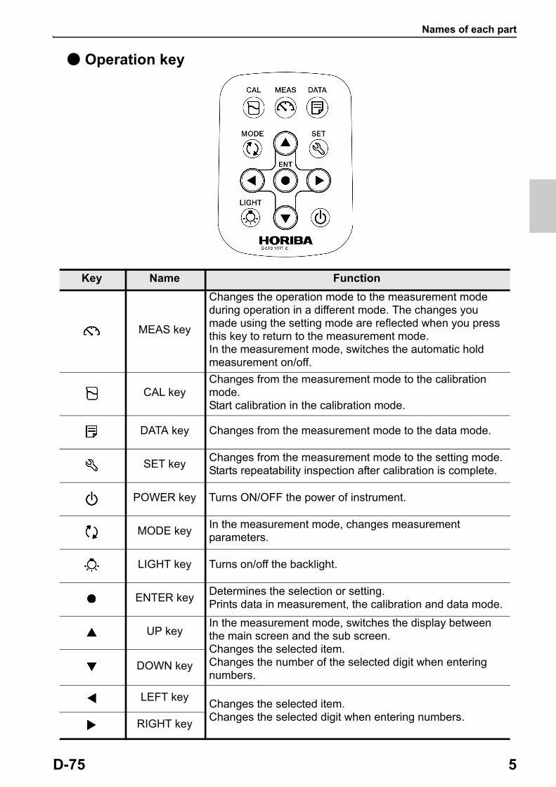
● Operation key
Key Name Function
MEAS key
Changes the operation mode to the measurement mode during operation in a different mode. The changes you made using the setting mode are reflected when you press this key to return to the measurement mode.In the measurement mode, switches the automatic hold measurement on/off.
CAL keyChanges from the measurement mode to the calibration mode.Start calibration in the calibration mode.
DATA key Changes from the measurement mode to the data mode.
SET keyChanges from the measurement mode to the setting mode.Starts repeatability inspection after calibration is complete.
POWER key Turns ON/OFF the power of instrument.
MODE keyIn the measurement mode, changes measurement parameters.
LIGHT key Turns on/off the backlight.
ENTER keyDetermines the selection or setting.Prints data in measurement, the calibration and data mode.
UP keyIn the measurement mode, switches the display between the main screen and the sub screen.Changes the selected item.Changes the number of the selected digit when entering numbers.
DOWN key
LEFT keyChanges the selected item.Changes the selected digit when entering numbers.
RIGHT key
Basic operation
6 HORIBA
■ Basic operation
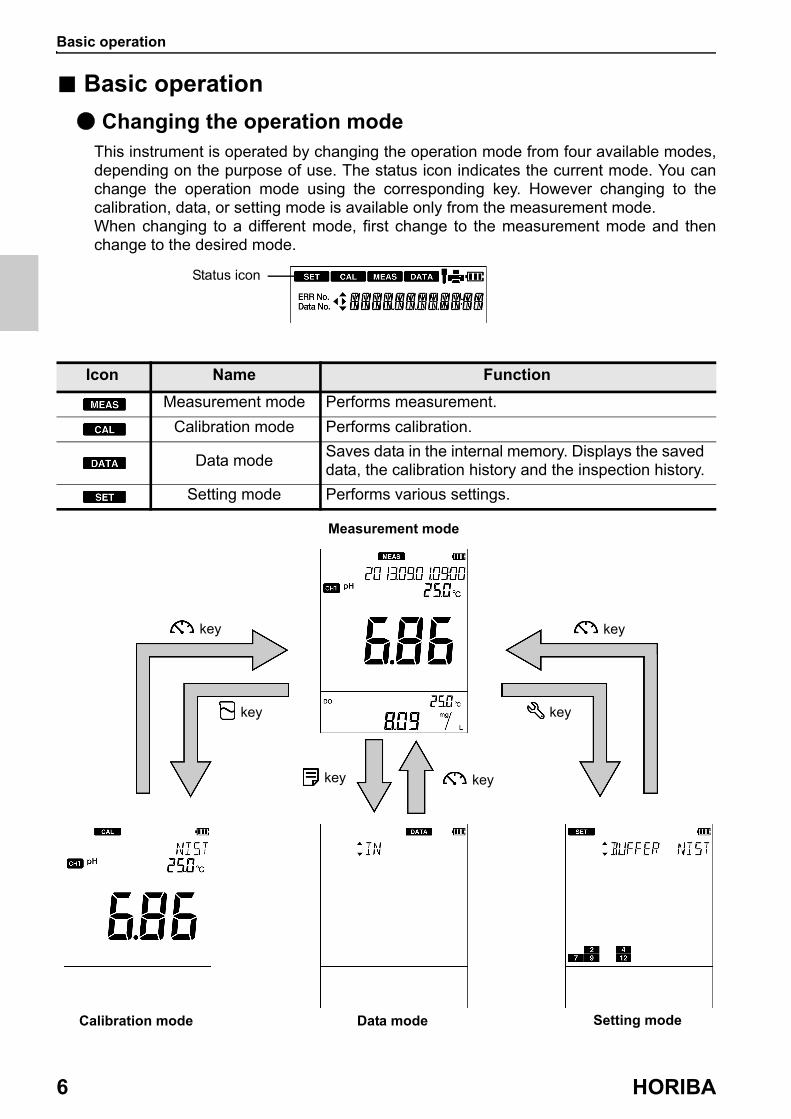
● Changing the operation modeThis instrument is operated by changing the operation mode from four available modes, depending on the purpose of use. The status icon indicates the current mode. You can change the operation mode using the corresponding key. However changing to the calibration, data, or setting mode is available only from the measurement mode.When changing to a different mode, first change to the measurement mode and then change to the desired mode.
Icon Name Function
Measurement mode Performs measurement.
Calibration mode Performs calibration.
Data modeSaves data in the internal memory. Displays the saved data, the calibration history and the inspection history.
Setting mode Performs various settings.
Status icon
key key
key key
key key
Data mode Setting modeCalibration mode
Measurement mode

Basic operation
D-75 7
● Switching the displaysYou can switch the channel between the main screen and the sub screen.
In the measurement mode, pressing the keys can switch the channels between the main screen and the sub screen.When performing calibration or setting, switch the display to show the desired channel (measurement parameter) on the main screen.
key
Basic operation
8 HORIBA
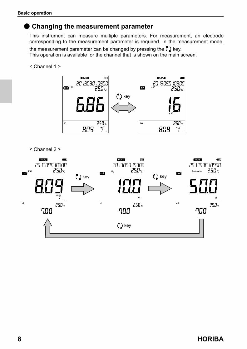
● Changing the measurement parameterThis instrument can measure multiple parameters. For measurement, an electrode corresponding to the measurement parameter is required. In the measurement mode,
the measurement parameter can be changed by pressing the key.This operation is available for the channel that is shown on the main screen.
< Channel 1 >
< Channel 2 >
key
key key
key

Basic operation
D-75 9
● Using the backlightWhen it is difficult to see the screen in a dark location, you can turn on the backlight by
pressing the key. If the backlight is not operated for 5 minutes, it automatically turns
off. To turn it off manually, press the key again while the backlight is on.
Note
・ Turning on the backlight consumes energy and shortens battery life.・ The backlight becomes unavailable when the battery level becomes low.
key

Basic operation
10 HORIBA
● Entering numeric valuesWhen entering numeric values to make various settings and set a calibration value, you
can change the selected digit using the keys and increment or decrement the value
(0 to 9) using the keys.
key
key
D-75 11
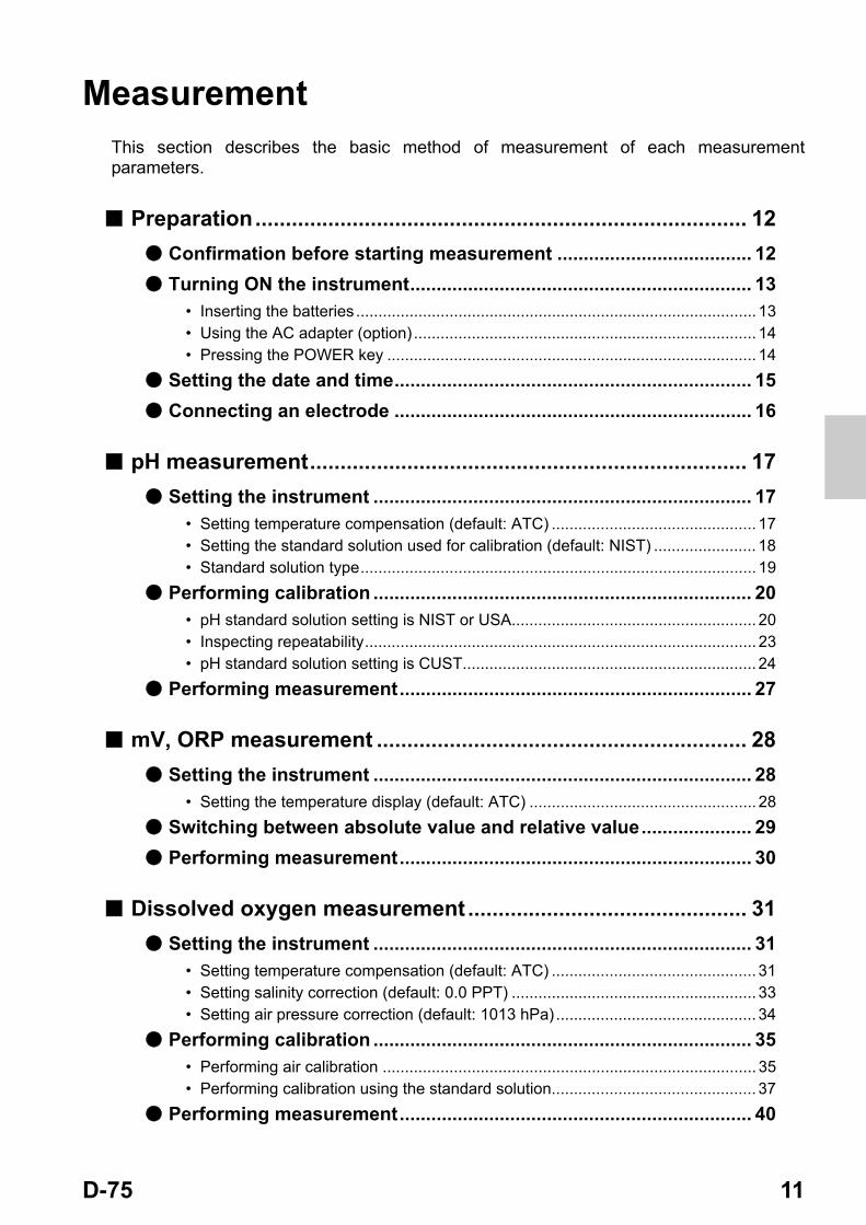
MeasurementThis section describes the basic method of measurement of each measurement parameters.
■ Preparation................................................................................. 12
● Confirmation before starting measurement ..................................... 12
● Turning ON the instrument................................................................. 13• Inserting the batteries .......................................................................................... 13• Using the AC adapter (option) ............................................................................. 14• Pressing the POWER key ................................................................................... 14
● Setting the date and time.................................................................... 15
● Connecting an electrode .................................................................... 16
■ pH measurement........................................................................ 17
● Setting the instrument ........................................................................ 17• Setting temperature compensation (default: ATC) .............................................. 17• Setting the standard solution used for calibration (default: NIST) ....................... 18• Standard solution type......................................................................................... 19
● Performing calibration ........................................................................ 20• pH standard solution setting is NIST or USA....................................................... 20• Inspecting repeatability........................................................................................ 23• pH standard solution setting is CUST.................................................................. 24
● Performing measurement................................................................... 27
■ mV, ORP measurement ............................................................. 28
● Setting the instrument ........................................................................ 28• Setting the temperature display (default: ATC) ................................................... 28
● Switching between absolute value and relative value..................... 29
● Performing measurement................................................................... 30
■ Dissolved oxygen measurement .............................................. 31
● Setting the instrument ........................................................................ 31• Setting temperature compensation (default: ATC) .............................................. 31• Setting salinity correction (default: 0.0 PPT) ....................................................... 33• Setting air pressure correction (default: 1013 hPa) ............................................. 34
● Performing calibration ........................................................................ 35• Performing air calibration .................................................................................... 35• Performing calibration using the standard solution.............................................. 37
● Performing measurement................................................................... 40
Preparation
12 HORIBA
■ Preparation
● Confirmation before starting measurement
・ Have you prepared the appropriate electrode for the measurement parameter?⇒ If not, purchase the appropriate electrode.
・ Is the prepared electrode in good condition?⇒ If the responsive part is stained or damaged, it may not be possible to obtain accurate values.
・ Have you prepared the appropriate standard solution for the measurement parameter?⇒ If not, prepare the standard solution by yourself or purchase it.
・ Are there any items that should not be wet or stained around the instrument?⇒Depending on the operation during measurement, items around the instrument could get wet or stained. Secure sufficient space around the instrument and perform measurement while always paying attention to safety.
・ Are there any devices that can be a source of noise?⇒ Measured values could be affected. Do not use the instrument near such devices. Always ground devices operated by AC power.
Preparation
D-75 13
● Turning ON the instrument
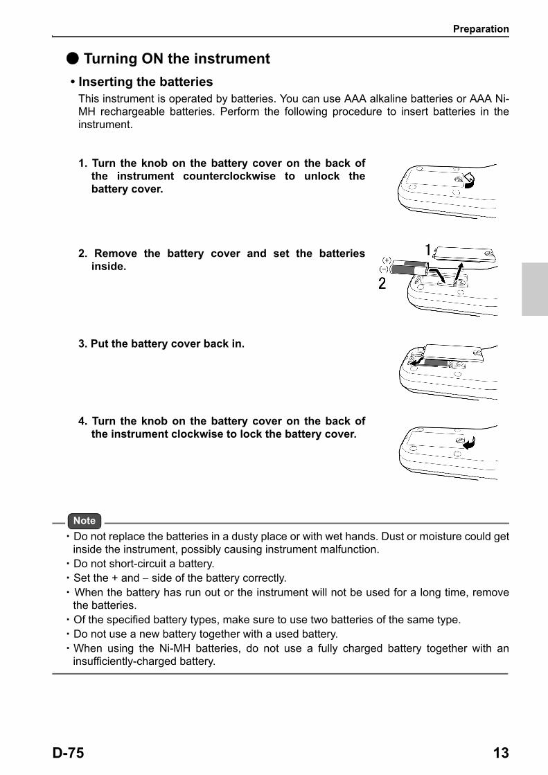
• Inserting the batteriesThis instrument is operated by batteries. You can use AAA alkaline batteries or AAA Ni- MH rechargeable batteries. Perform the following procedure to insert batteries in the instrument.
1. Turn the knob on the battery cover on the back of the instrument counterclockwise to unlock the battery cover.
2. Remove the battery cover and set the batteries inside.
3. Put the battery cover back in.
4. Turn the knob on the battery cover on the back of the instrument clockwise to lock the battery cover.
Note
・ Do not replace the batteries in a dusty place or with wet hands. Dust or moisture could get inside the instrument, possibly causing instrument malfunction.
・ Do not short-circuit a battery.・ Set the + and side of the battery correctly.・ When the battery has run out or the instrument will not be used for a long time, remove
the batteries.・ Of the specified battery types, make sure to use two batteries of the same type.・ Do not use a new battery together with a used battery.・ When using the Ni-MH batteries, do not use a fully charged battery together with an
insufficiently-charged battery.
Preparation
14 HORIBA
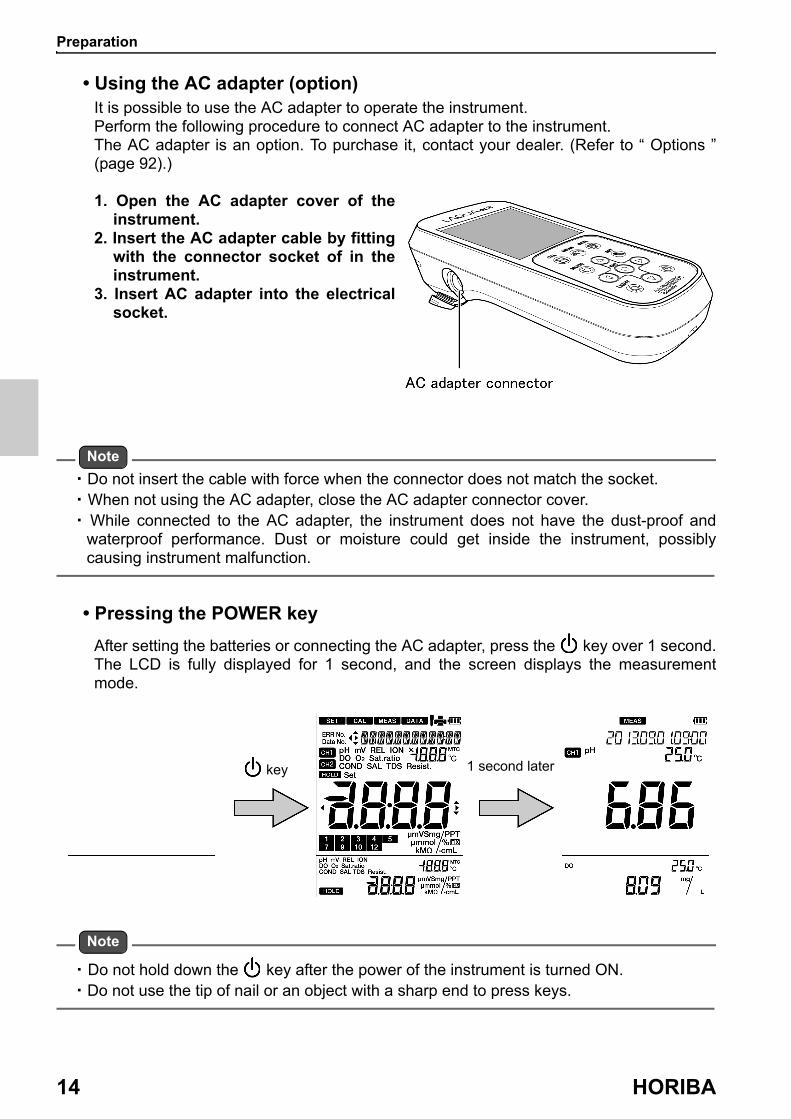
• Using the AC adapter (option)It is possible to use the AC adapter to operate the instrument.Perform the following procedure to connect AC adapter to the instrument.The AC adapter is an option. To purchase it, contact your dealer. (Refer to “ Options ” (page 92).)
1. Open the AC adapter cover of the instrument.
2. Insert the AC adapter cable by fitting with the connector socket of in the instrument.
3. Insert AC adapter into the electrical socket.
Note
・ Do not insert the cable with force when the connector does not match the socket.・ When not using the AC adapter, close the AC adapter connector cover. ・ While connected to the AC adapter, the instrument does not have the dust-proof and
waterproof performance. Dust or moisture could get inside the instrument, possibly causing instrument malfunction.
• Pressing the POWER key
After setting the batteries or connecting the AC adapter, press the key over 1 second. The LCD is fully displayed for 1 second, and the screen displays the measurement mode.
Note
・ Do not hold down the key after the power of the instrument is turned ON.・ Do not use the tip of nail or an object with a sharp end to press keys.
key 1 second later
Preparation
D-75 15
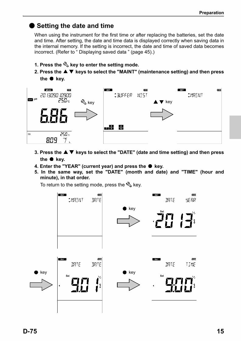
● Setting the date and timeWhen using the instrument for the first time or after replacing the batteries, set the date and time. After setting, the date and time data is displayed correctly when saving data in the internal memory. If the setting is incorrect, the date and time of saved data becomes incorrect. (Refer to “ Displaying saved data ” (page 45).)
1. Press the key to enter the setting mode.
2. Press the keys to select the "MAINT" (maintenance setting) and then press
the key.
3. Press the keys to select the "DATE" (date and time setting) and then press
the key.
4. Enter the "YEAR" (current year) and press the key.5. In the same way, set the "DATE" (month and date) and "TIME" (hour and
minute), in that order.
To return to the setting mode, press the key.
key key
key
key key

Preparation
16 HORIBA
Tip
To change to the setting again, press the key to return to the "DATE" (date and time
setting) screen. The settings on screen before the key is pressed are not saved.
● Connecting an electrodeTo perform measurement, you must use the appropriate electrode for measurement parameters. Recommended electrodes for each measured sample are listed in our product catalog and on our website. Refer to them when preparing electrodes. Use the following procedure to correctly connect the electrode to the instrument.
1. Insert the electrode connector by fitting its groove with the connector socket pin of the instrument.
2. Turn the electrode connector clockwise by following the groove.
3. Put the connector cover on the connector.
4. Insert the temperature connector into the jack socket on the instrument (only when using a combination electrode equipped with a temperature sensor).
Preparation for measurement is complete.For details of the measurement operation, refer to the following pages.
Electrode connector
Temperature connector
pH measurement
D-75 17
■ pH measurementYou can measure the pH of the sample with a pH electrode.Use a combination electrode incorporating a glass electrode and a reference electrode for measurement. A single glass electrode cannot be used with this instrument.pH can be measured using channel 1 of the instrument.
● Setting the instrument
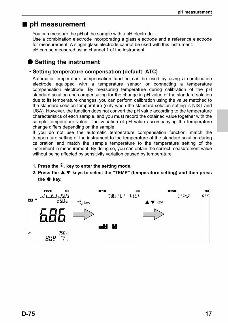
• Setting temperature compensation (default: ATC)Automatic temperature compensation function can be used by using a combination electrode equipped with a temperature sensor or connecting a temperature compensation electrode. By measuring temperature during calibration of the pH standard solution and compensating for the change in pH value of the standard solution due to its temperature changes, you can perform calibration using the value matched to the standard solution temperature (only when the standard solution setting is NIST and USA). However, the function does not convert the pH value according to the temperature characteristics of each sample, and you must record the obtained value together with the sample temperature value. The variation of pH value accompanying the temperature change differs depending on the sample.If you do not use the automatic temperature compensation function, match the temperature setting of the instrument to the temperature of the standard solution during calibration and match the sample temperature to the temperature setting of the instrument in measurement. By doing so, you can obtain the correct measurement value without being affected by sensitivity variation caused by temperature.
1. Press the key to enter the setting mode.
2. Press the keys to select the "TEMP" (temperature setting) and then press
the key.
key key
pH measurement
18 HORIBA
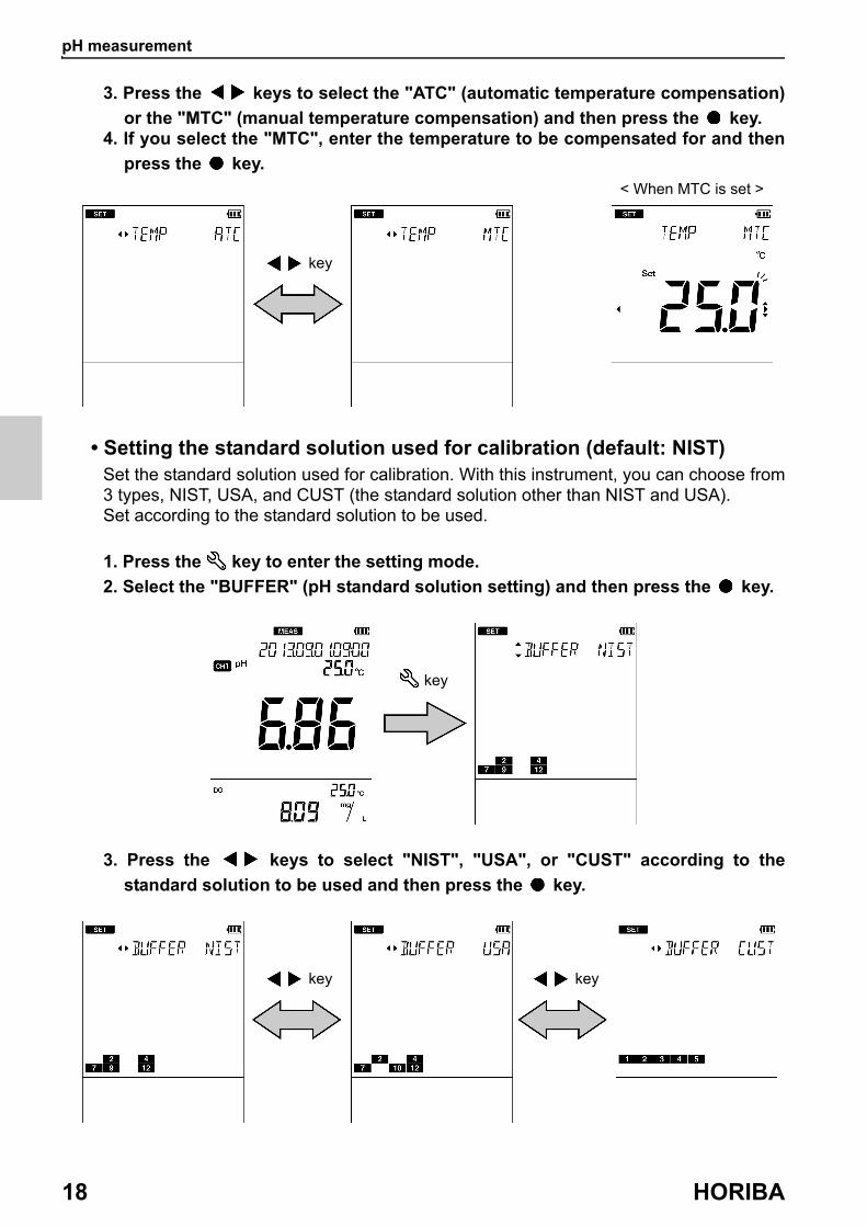
3. Press the keys to select the "ATC" (automatic temperature compensation)
or the "MTC" (manual temperature compensation) and then press the key. 4. If you select the "MTC", enter the temperature to be compensated for and then
press the key.
• Setting the standard solution used for calibration (default: NIST)Set the standard solution used for calibration. With this instrument, you can choose from 3 types, NIST, USA, and CUST (the standard solution other than NIST and USA).Set according to the standard solution to be used.
1. Press the key to enter the setting mode.
2. Select the "BUFFER" (pH standard solution setting) and then press the key.
3. Press the keys to select "NIST", "USA", or "CUST" according to the
standard solution to be used and then press the key.
key
< When MTC is set >
key
key key

pH measurement
D-75 19
• Standard solution type
Note
The calibration value of the pH 7 standard solution differs between NIST and USA.NIST: pH 6.865 (at 25°C)USA: pH 7.000 (at 25°C)
Standard solution type Description
NIST(Japanese specification)
Set to use the standard solution of the Japanese specification.
Standard solution icon
USA(USA specification)
Set to use the standard solution of the USA specification.
Standard solution icon
CUST(custom specification)
Set to use the standard solution of an optional specification.
Standard solution icon
pH measurement
20 HORIBA
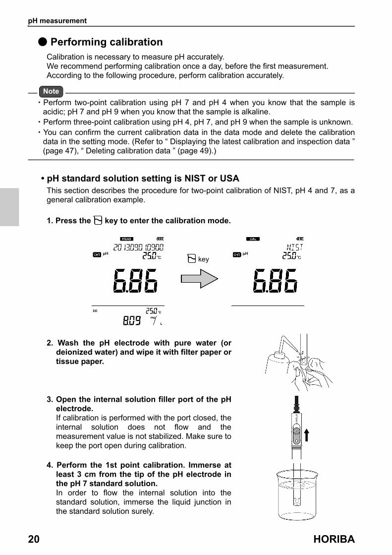
● Performing calibrationCalibration is necessary to measure pH accurately.We recommend performing calibration once a day, before the first measurement.According to the following procedure, perform calibration accurately.
Note
・ Perform two-point calibration using pH 7 and pH 4 when you know that the sample is acidic; pH 7 and pH 9 when you know that the sample is alkaline.
・ Perform three-point calibration using pH 4, pH 7, and pH 9 when the sample is unknown.・ You can confirm the current calibration data in the data mode and delete the calibration
data in the setting mode. (Refer to “ Displaying the latest calibration and inspection data ” (page 47), “ Deleting calibration data ” (page 49).)
• pH standard solution setting is NIST or USAThis section describes the procedure for two-point calibration of NIST, pH 4 and 7, as a general calibration example.
1. Press the key to enter the calibration mode.
2. Wash the pH electrode with pure water (or deionized water) and wipe it with filter paper or tissue paper.
3. Open the internal solution filler port of the pH electrode.If calibration is performed with the port closed, the internal solution does not flow and the measurement value is not stabilized. Make sure to keep the port open during calibration.
4. Perform the 1st point calibration. Immerse at least 3 cm from the tip of the pH electrode in the pH 7 standard solution.In order to flow the internal solution into the standard solution, immerse the liquid junction in the standard solution surely.
key
pH measurement
D-75 21
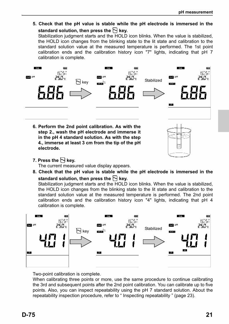
5. Check that the pH value is stable while the pH electrode is immersed in the
standard solution, then press the key.Stabilization judgment starts and the HOLD icon blinks. When the value is stabilized, the HOLD icon changes from the blinking state to the lit state and calibration to the standard solution value at the measured temperature is performed. The 1st point calibration ends and the calibration history icon "7" lights, indicating that pH 7 calibration is complete.
6. Perform the 2nd point calibration. As with the step 2., wash the pH electrode and immerse it in the pH 4 standard solution. As with the step 4., immerse at least 3 cm from the tip of the pH electrode.
7. Press the key.The current measured value display appears.
8. Check that the pH value is stable while the pH electrode is immersed in the
standard solution, then press the key.Stabilization judgment starts and the HOLD icon blinks. When the value is stabilized, the HOLD icon changes from the blinking state to the lit state and calibration to the standard solution value at the measured temperature is performed. The 2nd point calibration ends and the calibration history icon "4" lights, indicating that pH 4 calibration is complete.
Two-point calibration is complete.When calibrating three points or more, use the same procedure to continue calibrating the 3rd and subsequent points after the 2nd point calibration. You can calibrate up to five points. Also, you can inspect repeatability using the pH 7 standard solution. About the repeatability inspection procedure, refer to “ Inspecting repeatability ” (page 23).
Stabilized key
Stabilized key

pH measurement
22 HORIBA
Tip
・ You can cancel calibration by pressing the key while the HOLD icon is blinking.・ The order of calibration of the standard solution is optional.
In the above example, you can calibrate pH 4 first and then pH 7.
Note
If calibration of any standard solution is performed again in the calibration mode, only the value of calibrated solution is updated. If you change to the measurement mode and then enter the calibration mode to perform calibration again, all previous data is updated.
Confirming the pH electrode statusAfter calibration is complete, the current pH electrode status is diagnosed from the calibration result. Use this information for maintenance of the electrode.
Display Description Reference
Both , ERR No.are not displayed
Electrode sensitivity: 93% to 100%Good condition. -
blinksElectrode sensitivity: 90% to 93%Urgent measures are not required but attention is necessary.
P. 68
lightsElectrode sensitivity: 85% to 90%Check the electrode immediately.
P. 68
ERR No.0004The asymmetry potential is out of the setting range that allows proper measurement.Maintain or replace the electrode.
P. 74
ERR No.0005The sensitivity is out of the setting range that allows proper measurement.Maintain or replace the electrode.
P. 75

pH measurement
D-75 23
• Inspecting repeatability
You can inspect repeatability using the pH 7 standard solution by pressing the key on the screen after calibration. Measure the pH 7 standard solution by using the calibrated electrode to display the absolute value of the difference between the measured value and standard solution value.In order to inspect repeatability, you need to perform calibration of the pH 7 standard solution with either "NIST" or "USA" set as the standard solution.
1. Wash the calibrated pH electrode with pure water (or deionized water) and wipe it with filter paper or tissue paper.
2. Open the internal solution filler port of the pH electrode.If calibration is performed with the port closed, the internal solution does not flow and the measurement value is not stabilized. Make sure to keep the port open during calibration.
3. Immerse at least 3 cm from the tip of the pH electrode in the pH 7 standard solution.In order to flow the internal solution into the standard solution, immerse the liquid junction in the standard solution surely.
4. While the pH electrode is immersed in the standard solution, press the key.Stabilization judgment starts and the HOLD icon blinks. When the value is stabilized, the HOLD icon changes from the blinking state to the lit state and the display is fixed to the measured value at the stable time.
Note
Repeatability inspection can be performed only once for one calibration.
Stabilized key

pH measurement
24 HORIBA
• pH standard solution setting is CUSTThis section describes the procedure for two-point calibration.
1. Press the key to enter the calibration mode and enter the standard solution value for the 1st point calibration.The current measured value is displayed on the sub screen.
2. Wash the pH electrode with pure water (or deionized water) and wipe it with filter paper or tissue paper.
3. Open the internal solution filler port of the pH electrode.If calibration is performed with the port closed, the internal solution does not flow and the measurement value is not stabilized. Make sure to keep the port open during calibration.
4. Perform the 1st point calibration. Immerse at least 3 cm from the tip of the pH electrode in standard solution of the value entered in step 1.In order to flow the internal solution into the standard solution, immerse the liquid junction in the standard solution surely.
key
pH measurement
D-75 25
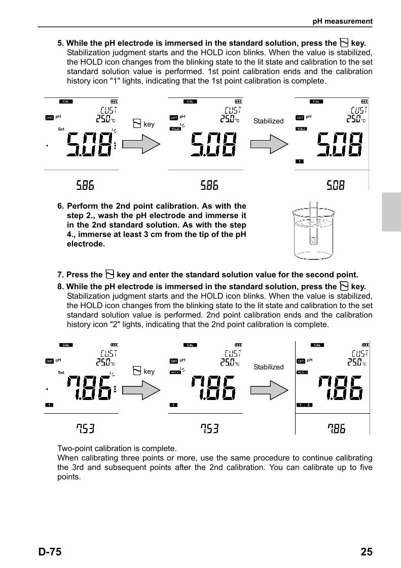
5. While the pH electrode is immersed in the standard solution, press the key.Stabilization judgment starts and the HOLD icon blinks. When the value is stabilized, the HOLD icon changes from the blinking state to the lit state and calibration to the set standard solution value is performed. 1st point calibration ends and the calibration history icon "1" lights, indicating that the 1st point calibration is complete.
6. Perform the 2nd point calibration. As with the step 2., wash the pH electrode and immerse it in the 2nd standard solution. As with the step 4., immerse at least 3 cm from the tip of the pH electrode.
7. Press the key and enter the standard solution value for the second point.
8. While the pH electrode is immersed in the standard solution, press the key.Stabilization judgment starts and the HOLD icon blinks. When the value is stabilized, the HOLD icon changes from the blinking state to the lit state and calibration to the set standard solution value is performed. 2nd point calibration ends and the calibration history icon "2" lights, indicating that the 2nd point calibration is complete.
Two-point calibration is complete.When calibrating three points or more, use the same procedure to continue calibrating the 3rd and subsequent points after the 2nd calibration. You can calibrate up to five points.
Stabilized key
Stabilized key
pH measurement
26 HORIBA
Tip
You can cancel calibration by pressing the key while the HOLD icon is blinking.
Note
If calibration of any standard solution is performed again in the calibration mode, only the value of calibrated solution is updated. If you change to the measurement mode and then enter the calibration mode to perform calibration again, all previous data is updated.
Confirming the pH electrode statusAfter calibration is complete, the current pH electrode status is diagnosed from the calibration result. Use this information for maintenance of the electrode.
Display Description Reference
Both , ERR No.are not displayed
Electrode sensitivity: 93% to 100%Good condition. -
blinksElectrode sensitivity: 90% to 93%Urgent measures are not required but attention is necessary.
P. 68
lightsElectrode sensitivity: 85% to 90%Check the electrode immediately.
P. 68
ERR No.0004The asymmetry potential is out of the setting range that allows proper measurement.Maintain or replace the electrode.
P. 74
ERR No.0005The sensitivity is out of the setting range that allows proper measurement.Maintain or replace the electrode.
P. 75
pH measurement
D-75 27
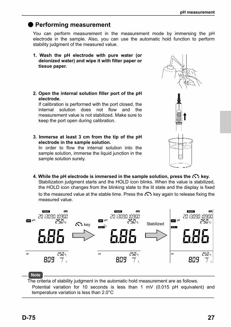
● Performing measurementYou can perform measurement in the measurement mode by immersing the pH electrode in the sample. Also, you can use the automatic hold function to perform stability judgment of the measured value.
1. Wash the pH electrode with pure water (or deionized water) and wipe it with filter paper or tissue paper.
2. Open the internal solution filler port of the pH electrode.If calibration is performed with the port closed, the internal solution does not flow and the measurement value is not stabilized. Make sure to keep the port open during calibration.
3. Immerse at least 3 cm from the tip of the pH electrode in the sample solution.In order to flow the internal solution into the sample solution, immerse the liquid junction in the sample solution surely.
4. While the pH electrode is immersed in the sample solution, press the key.Stabilization judgment starts and the HOLD icon blinks. When the value is stabilized, the HOLD icon changes from the blinking state to the lit state and the display is fixed
to the measured value at the stable time. Press the key again to release fixing the measured value.
Note
The criteria of stability judgment in the automatic hold measurement are as follows. Potential variation for 10 seconds is less than 1 mV (0.015 pH equivalent) and
temperature variation is less than 2.0°C
key Stabilized
mV, ORP measurement
28 HORIBA
■ mV, ORP measurementThe mV measurement measures the electromotive force between the electrode and the sample by using a pH electrode. The measured value can be used to understand the status of the electrode after using the standard solution.The ORP measurement measures the ORP (oxidation-reduction potential) of the sample by using an ORP electrode.
In the measurement mode, press the key to change the measurement parameter to "mV".mV and ORP can be measured using channel 1 of the instrument.
● Setting the instrument
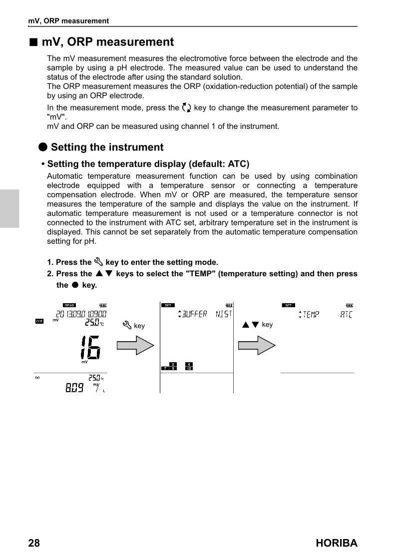
• Setting the temperature display (default: ATC)Automatic temperature measurement function can be used by using combination electrode equipped with a temperature sensor or connecting a temperature compensation electrode. When mV or ORP are measured, the temperature sensor measures the temperature of the sample and displays the value on the instrument. If automatic temperature measurement is not used or a temperature connector is not connected to the instrument with ATC set, arbitrary temperature set in the instrument is displayed. This cannot be set separately from the automatic temperature compensation setting for pH.
1. Press the key to enter the setting mode.
2. Press the keys to select the "TEMP" (temperature setting) and then press
the key.
key key
mV, ORP measurement
D-75 29
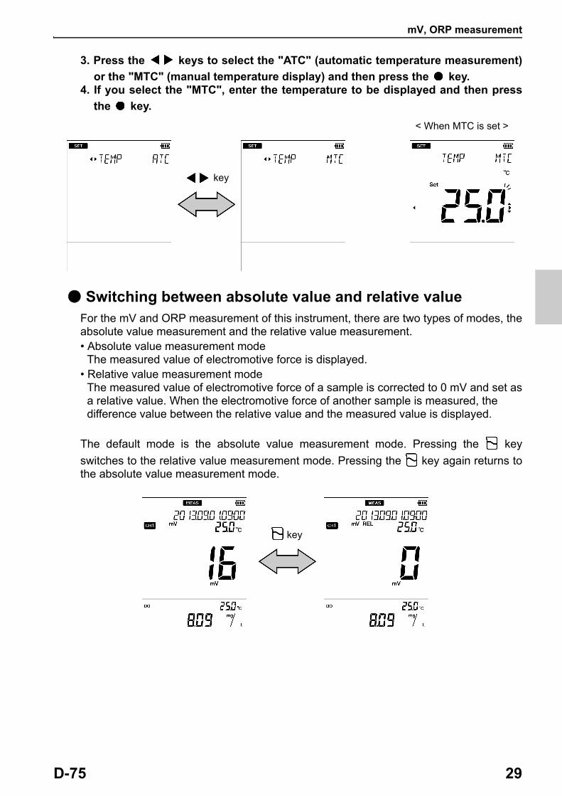
3. Press the keys to select the "ATC" (automatic temperature measurement)
or the "MTC" (manual temperature display) and then press the key.4. If you select the "MTC", enter the temperature to be displayed and then press
the key.
● Switching between absolute value and relative valueFor the mV and ORP measurement of this instrument, there are two types of modes, the absolute value measurement and the relative value measurement.• Absolute value measurement mode
The measured value of electromotive force is displayed.• Relative value measurement mode
The measured value of electromotive force of a sample is corrected to 0 mV and set asa relative value. When the electromotive force of another sample is measured, thedifference value between the relative value and the measured value is displayed.
The default mode is the absolute value measurement mode. Pressing the key
switches to the relative value measurement mode. Pressing the key again returns to the absolute value measurement mode.
key
< When MTC is set >
key

mV, ORP measurement
30 HORIBA
● Performing measurementYou can perform measurement in the measurement mode by immersing the electrode in the sample. Also, you can use the automatic hold function to perform stability judgment of the measured value.
1. Wash the electrode with pure water (or deionized water) and wipe it with filter paper or tissue paper.
2. Open the internal solution filler port of the electrode.If calibration is performed with the port closed, the internal solution does not flow and the measurement value is not stabilized. Make sure to keep the port open during calibration.
3. Immerse at least 3 cm from the tip of the electrode in the sample solution.In order to flow the internal solution into the sample solution, immerse the liquid junction in the sample solution surely.
4. While the electrode is immersed in the sample solution, press the key.Stabilization judgment starts and the HOLD icon blinks. When the value is stabilized, the HOLD icon changes from the blinking state to the lit state and the display is fixed
to the measured value at the stable time. Press the key again to release fixing the measured value.
Note
・ The criteria of stability judgment in the automatic hold measurement are as follows.Potential variation for 10 seconds is less than 1 mV and temperature variation is less than 2.0°C
・ Note that when measuring the ORP of a sample solution that has extremely low concentrations of oxidants and reductants (such as tap water, well water, or water treated with purifying equipment), there may be less responsiveness and repeatability in general.
・ If alkaline water is left, its ORP value changes considerably. Always measure alkaline Ion water promptly.
key Stabilized

Dissolved oxygen measurement
D-75 31
■ Dissolved oxygen measurementYou can use the DO electrode to measure the dissolved oxygen, oxygen concentration, and saturated oxygen concentration of a sample. Oxygen concentration and saturated oxygen concentration are calculated from the measured value of dissolved oxygen.
Press the key to select the measurement parameter (“ Changing the measurement parameter ” (page 8)).The operation is the same for all measurement parameters.These measurement parameters can be measured using channel 2 of the instrument.
Press the keys to set the main screen to channel 2.
● Setting the instrument
• Setting temperature compensation (default: ATC)Because a temperature sensor is equipped with the DO electrode, you can use the automatic temperature compensation function. During calibration, compensating for the change in dissolved oxygen due to temperature change by measuring the temperature of the air (when air calibration is performed) or the standard solution (when standard solution calibration is performed). This function allows you to correct the sensitivity of the calibration data according to the sample temperature.If you do not use the automatic temperature compensation function, match the temperature setting of the instrument to the temperature of the air (when air calibration is performed) or the standard solution (when standard solution calibration is performed) during calibration and perform measurement by matching the sample temperature to the temperature setting of the instrument. By doing so, you can obtain the correct measurement value without being affected by sensitivity changes caused by temperature.
1. Press the key to enter the setting mode.
2. Select the "TEMP" (temperature setting) and then press the key.
key
Dissolved oxygen measurement
32 HORIBA
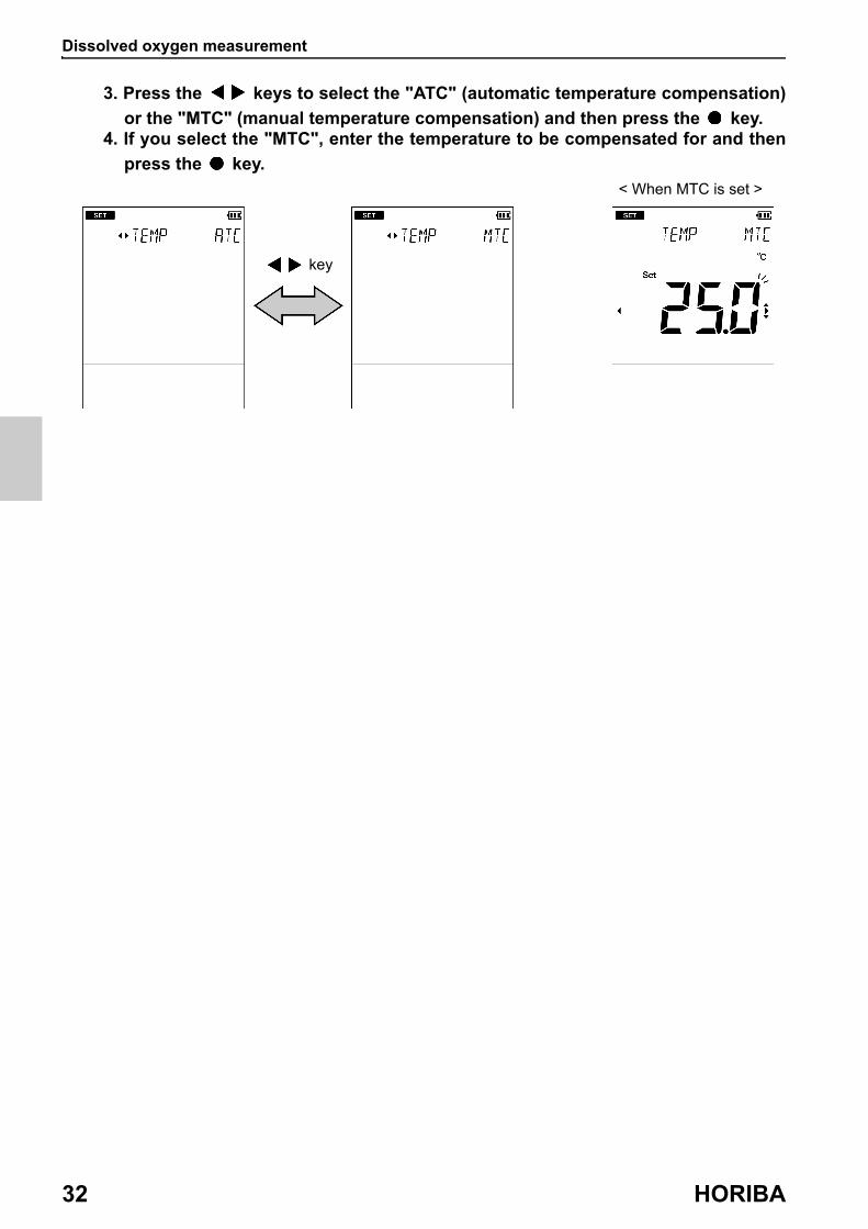
3. Press the keys to select the "ATC" (automatic temperature compensation)
or the "MTC" (manual temperature compensation) and then press the key.4. If you select the "MTC", enter the temperature to be compensated for and then
press the key.
key
< When MTC is set >
Dissolved oxygen measurement
D-75 33
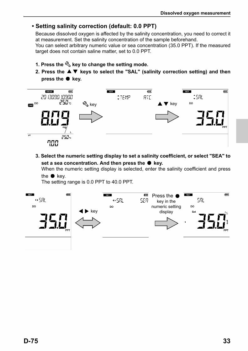
• Setting salinity correction (default: 0.0 PPT)Because dissolved oxygen is affected by the salinity concentration, you need to correct it at measurement. Set the salinity concentration of the sample beforehand. You can select arbitrary numeric value or sea concentration (35.0 PPT). If the measured target does not contain saline matter, set to 0.0 PPT.
1. Press the key to change the setting mode.
2. Press the keys to select the "SAL" (salinity correction setting) and then
press the key.
3. Select the numeric setting display to set a salinity coefficient, or select "SEA" to
set a sea concentration. And then press the key.When the numeric setting display is selected, enter the salinity coefficient and press
the key.The setting range is 0.0 PPT to 40.0 PPT.
key key
key
Press the key in the
numeric setting display
Dissolved oxygen measurement
34 HORIBA
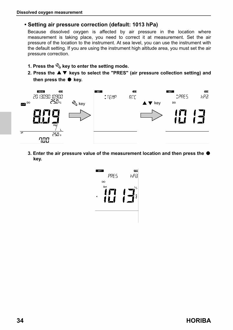
• Setting air pressure correction (default: 1013 hPa)Because dissolved oxygen is affected by air pressure in the location where measurement is taking place, you need to correct it at measurement. Set the air pressure of the location to the instrument. At sea level, you can use the instrument with the default setting. If you are using the instrument high altitude area, you must set the air pressure correction.
1. Press the key to enter the setting mode.
2. Press the keys to select the "PRES" (air pressure collection setting) and
then press the key.
3. Enter the air pressure value of the measurement location and then press the key.
key key

Dissolved oxygen measurement
D-75 35
● Performing calibrationCalibration of the DO electrode is required for accurate measurements. According to the following procedure, perform calibration correctly.You can perform air one-point calibration and two-point calibration using the standard solution with this instrument. We recommend that calibration be performed once a day before the first measurement.
Note
To perform accurate calibration, set the air pressure value before calibration (“ Setting air pressure correction (default: 1013 hPa) ” (page 34)).
• Performing air calibrationThis section describes the method of air one-point calibration.
Note
・ Air calibration must be performed in clean air. If air calibration is performed in a location subject to dramatic temperature swings, exposed to wind and rain, or near a heating appliance, an error may occur or the value may not be stabilized.
・ Do not hold the DO electrode during calibration with hand. DO electrode may be affected by temperature, causing an unstable value.
1. Wash the membrane at the tip of the DO electrode with pure water (or deionized water) and wipe it with a soft cloth at least 10 minutes before calibration.Be careful not to break the membrane at the tip of the electrode.
2. Press the key to enter the calibration mode.
key

Dissolved oxygen measurement
36 HORIBA
3. Hold the DO electrode still in clean air and press the key.Stabilization judgment starts and the HOLD icon blinks. When the value is stabilized, the HOLD icon changes from the blinking state to the lit state and the calibrated value is displayed (the calibrated value differs depending on the conditions because it is affected by temperature and air pressure).
Tip
You can cancel calibration by pressing the key while the HOLD icon is blinking.
Stabilized key

Dissolved oxygen measurement
D-75 37
• Performing calibration using the standard solutionIf high precision measurement is necessary, perform two-point calibration using the standard solution.
1. Wash the membrane at the tip of the DO electrode with pure water (or deionized water) and wipe it with a soft cloth at least 10 minutes before calibration.Be careful not to break the membrane at the tip of the electrode.
2. Prepare the standard solution to be used for calibration.・ Preparing the zero standard solution
Add 50 g sodium sulfite (Na2SO3) into 1000 mL pure water (or deionized water) and stir until sodium sulfite completely dissolves.
・ Preparing the span standard solutionUse an air pump to bubble pure water (or deionized water) in a container for about an hour to create oxygen saturated condition.
3. Press the key to enter the calibration mode.
4. Press the key to change to standard solution calibration.
Pressing the key again changes back to air calibration.
5. Perform the 1st point calibration. Immerse at least 6 cm from the tip of the DO electrode in the zero standard solution.In order to immerse the temperature sensor equipped with the electrode in the standard solution, immerse it at least 6 cm of the standard solution.During measurement, use a stirrer to stir the standard solution at 1000 rpm to 1500 rpm.
Note
・ If the temperature of the standard solution rises due to the use of a stirrer, use a temperature controlled bath.
・ When using an electrode "9551-20D" or "9551-100D", immerse at least 9 cm from the tip.
key key

Dissolved oxygen measurement
38 HORIBA
6. While the DO electrode is immersed in the standard solution, press the key.Stabilization judgment starts and the HOLD icon blinks. When the value is stabilized, the HOLD icon changes from the blinking state to the lit state and calibration to the standard solution value is performed. Also, "ZERO" is displayed, indicating completion of zero calibration.
7. Perform the 2nd point calibration. As with the step 1., wash the DO electrode and immerse in the span standard solution. As with the step 5., immerse at least 6 cm from the tip of the DO electrode.To maintain oxygen saturated status, continue bubbling until calibration is finished.
Note
When using an electrode "9551-20D" or "9551-100D", immerse at least 9 cm from the tip.
8. While the DO electrode is immersed in the standard solution, press the key.Stabilization judgment starts and the HOLD icon blinks. When the value is stabilized, the HOLD icon changes from the blinking state to the lit state and calibration to the standard solution value is performed. Also, "SPAN" is displayed, indicating completion of span calibration.
Calibration using the standard solution is complete.
Tip
You can cancel calibration by pressing the key while the HOLD icon is blinking.
Stabilized key
Stabilized key

Dissolved oxygen measurement
D-75 39
Note
・ The zero standard solution and the span standard solution are determined automatically by the instrument. Also, the order of calibration is free.
・ If calibration of any standard solution is performed again in the calibration mode, only the value of calibrated solution is updated. If you change to the measurement mode and then enter the calibration mode to perform calibration again, all previous data is updated.

Dissolved oxygen measurement
40 HORIBA
● Performing measurementYou can perform measurement in the measurement mode by immersing the DO electrode in the sample. Also, you can use the automatic hold function to perform stability judgment of the measured value.
1. Press the key to change the parameter to measure.2. Wash the membrane at the tip of the DO
electrode with pure water (or deionized water) and wipe it with a soft cloth at least 10 minutes before calibration.Be careful not to break the membrane at the tip of the electrode.
3. Immerse at least 6 cm from the tip of the DO electrode in the sample solution.In order to immerse the temperature sensor equipped with the electrode in the sample solution, immerse it at least 6 cm of the sample solution.During measurement, use a stirrer to stir the sam- ple solution at 1000 rpm to 1500 rpm.
Note
When using an electrode "9551-20D" or "9551-100D", immerse at least 9 cm from the tip.
4. While the DO electrode is immersed in the sample solution, press the key.Stabilization judgment starts and the HOLD icon blinks. When the value is stabilized, the HOLD icon changes from the blinking state to the lit state and the display is fixed
to the measured value at the stable time. Pressing the key again releases fixing the measured value.
key Stabilized

Dissolved oxygen measurement
D-75 41
Note
The criteria of stability judgment in the automatic hold measurement are as follows.Dissolved oxygen: display value change for 10 seconds is less than 0.03
mg/L and temperature change is less than 2.0°COxygen concentration: display value change for 10 seconds is less than
0.3% and temperature change is less than 2.0°C Saturated oxygen concentration: display value change for 10 seconds is less than
0.1% and temperature change is less than 2.0°C
M E M O
42 HORIBA
D-75 43
Using various functionsThis section describes functions available in this instrument.
● Saving measurement data in the internal memory .......................... 42
● Displaying saved data......................................................................... 43
● Deleting all saved data........................................................................ 44
● Displaying the latest calibration and inspection data ..................... 45• Displaying the latest calibration data................................................................... 45
• Displaying the latest inspection data ................................................................... 46
● Deleting calibration data..................................................................... 47
● Printing measured values and calibration data................................ 48
● Transferring saved data to a PC ........................................................ 54
● Operating the instrument from an external device .......................... 55
● Using the automatic data save (default: OFF) .................................. 56
● Setting the ID number (default: 000).................................................. 58
● Using the calibration interval alarm (default: OFF).......................... 59
● Calibrating temperature sensor ......................................................... 60
● Changing the automatic power off setting (default: OFF)............... 61
● Performing test printing of the printer unit....................................... 62
● Resetting to factory default settings ................................................. 63

Saving measurement data in the internal memory
44 HORIBA
● Saving measurement data in the internal memoryUp to 1000 data items measured by the instrument can be stored in the internal memory of the instrument. The measurement data is saved in the internal memory in the measurement mode, except during the automatic hold measurement.
1. While the data to save is displayed, press the key to enter the data mode.
2. Select "IN" (data saving) and press the key.Saved data is displayed for 2 seconds and the "IN" appears automatically.
Note
If 1000 data items have already been saved, an error occurs and "ERR No. 0010" is displayed. Copy or transfer necessary data to a PC and delete the data from the memory (“ Deleting all saved data ” (page 46)).
key key
Displaying saved data
D-75 45
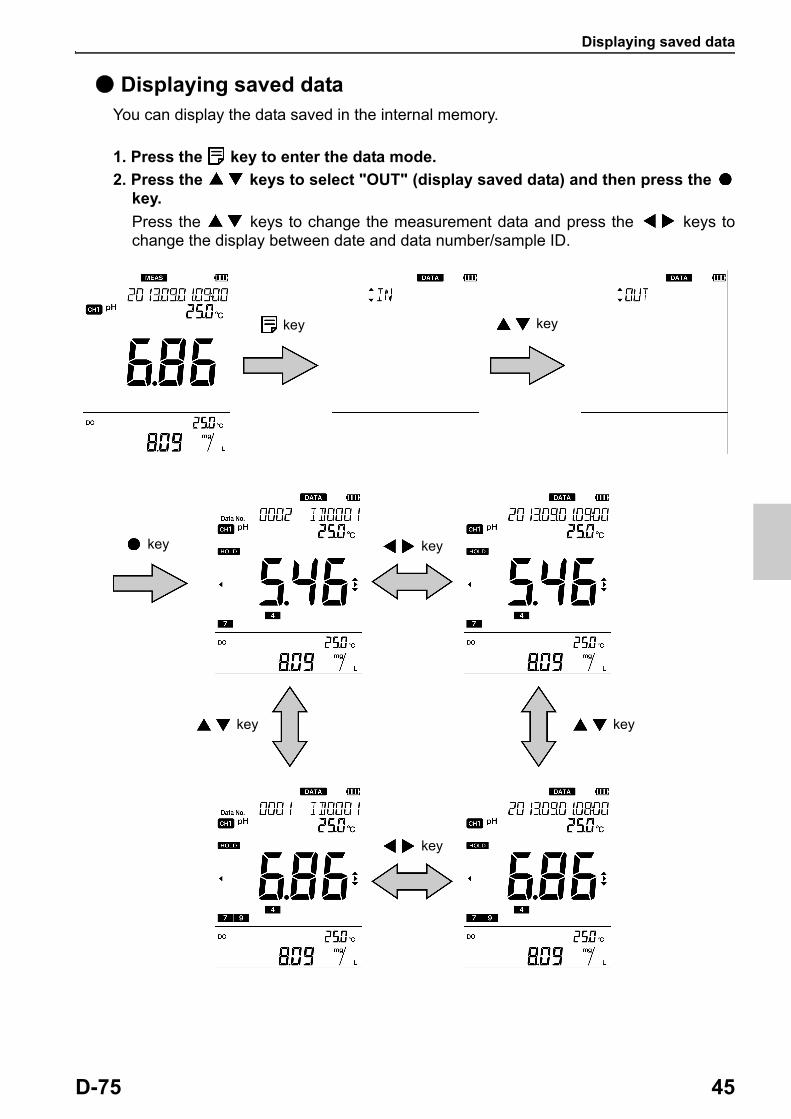
● Displaying saved dataYou can display the data saved in the internal memory.
1. Press the key to enter the data mode.
2. Press the keys to select "OUT" (display saved data) and then press the key.
Press the keys to change the measurement data and press the keys to change the display between date and data number/sample ID.
key key
key key
key key
key
Deleting all saved data
46 HORIBA
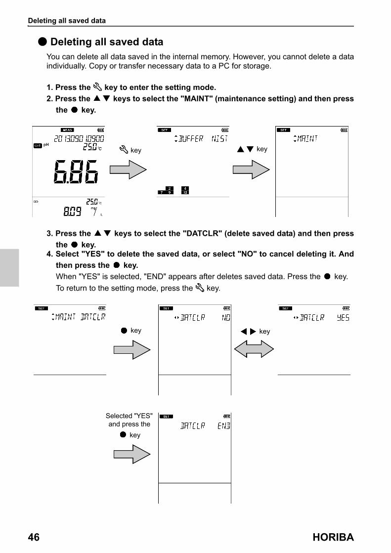
● Deleting all saved dataYou can delete all data saved in the internal memory. However, you cannot delete a data individually. Copy or transfer necessary data to a PC for storage.
1. Press the key to enter the setting mode.
2. Press the keys to select the "MAINT" (maintenance setting) and then press
the key.
3. Press the keys to select the "DATCLR" (delete saved data) and then press
the key.4. Select "YES" to delete the saved data, or select "NO" to cancel deleting it. And
then press the key.
When "YES" is selected, "END" appears after deletes saved data. Press the key.
To return to the setting mode, press the key.
key key
key key
Selected "YES" and press the
key

Displaying the latest calibration and inspection data
D-75 47
● Displaying the latest calibration and inspection dataYou can display the latest pH calibration data and repeatability inspection data.
• Displaying the latest calibration data
1. Press the key to enter the data mode.
2. Press the keys to select "CAL (pH or ION)" (display calibration data) and
then press the key.The electrode status based on the calibration result is displayed. You can change the display item between the asymmetry potential and the sensitivity.
key key
key
key key
key
Electrode status display
Sensitivity displayAsymmetry potential display
Displaying the latest calibration and inspection data
48 HORIBA
・ Electrode status based on calibration result
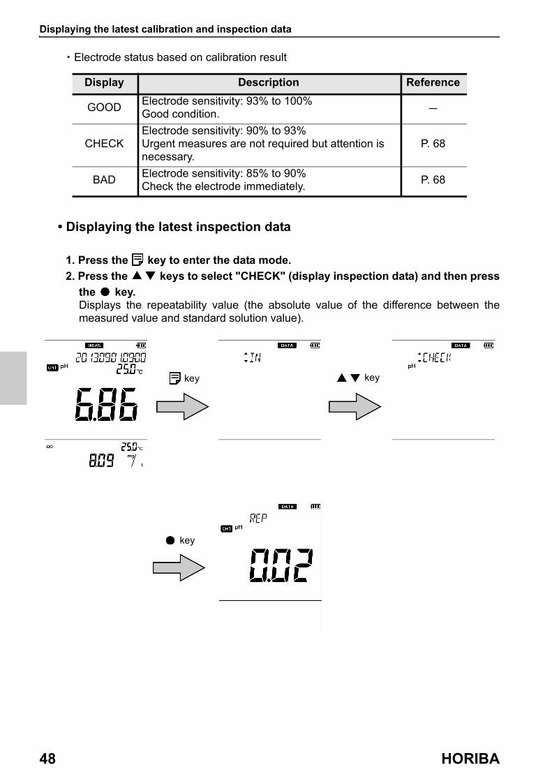
• Displaying the latest inspection data
1. Press the key to enter the data mode.
2. Press the keys to select "CHECK" (display inspection data) and then press
the key.Displays the repeatability value (the absolute value of the difference between the measured value and standard solution value).
Display Description Reference
GOODElectrode sensitivity: 93% to 100%Good condition. -
CHECKElectrode sensitivity: 90% to 93%Urgent measures are not required but attention is necessary.
P. 68
BADElectrode sensitivity: 85% to 90%Check the electrode immediately.
P. 68
key key
key

Deleting calibration data
D-75 49
● Deleting calibration dataYou can delete the calibration data set in the instrument.
1. Press the key to enter the setting mode.
2. Press the keys to select the "MAINT" (maintenance setting) and then press
the key.
3. Press the keys to select the "CALCLR" (delete calibration data) and then
press the key.
4. Press the keys to select the measurement parameter to delete and then
press the key.
5. Select "YES" to delete the calibration data, or select "NO" to cancel deleting it.
And then press the key.
When "YES" is selected, "END" appears after deletes calibration data. Press the key.
To return to the setting mode, press the key.
key key
key key
key
Selected "YES" and press the
key

Printing measured values and calibration data
50 HORIBA
● Printing measured values and calibration dataYou can print out the measured value or calibrated value displayed on the instrument, or the measurement data or the calibration data saved in the instrument. If repeatability inspection has been inspected, the inspection data is printed out with the calibration data.
Pressing the key starts printing during displaying the data you want to save. Use the printer cable (“ Options ” (page 92)) to connect the printer unit with the instrument beforehand. If the automatic data memory is set to "ON", you cannot print out in the measurement mode.Measurement data is printed out both channel 1 and channel 2.
Reference
For details of how to display measurement data and calibration data, refer to the respective section. “ Displaying saved data ” (page 45) “ Displaying the latest calibration and inspection data ” (page 47)
The format of the printout is shown on the next page when using pH (two point calibration) and dissolved oxygen.

Printing measured values and calibration data
D-75 51
< Measurement data >
Printout format Description
Date : 2013/09/01 Measurement date
Time : 09 : 00 Measurement time
Channel : 1 Measurement channel
pH : 5.22 Measured value
HOLD : AUTOHOLD statusHold value: AUTONot hold value: INST
Temperature : 25.5°C ATC Temperature value and temperature setting
Sample : 0000 Sample ID number
Inst. model : D-75 Instrument model
Inst. SN : KL1TSN36 Instrument serial number
Elect. status : OK Electrode status based on calibration result
Offset : 0.7 mV Asymmetry potential of calibration data
Sensitivity Sensitivity of calibration data
pH 4.01 - 6.86 : 98.9%
Date : 2013/09/01 Measurement date
Time : 09 : 00 Measurement time
Channel : 2 Measurement channel
DO : 1.03 mg/L Measured value
HOLD : AUTOHOLD statusHold value: AUTONot hold value: INST
Temperature : 25.5°C ATC Temperature value and temperature setting
Sample : 0000 Sample ID number
Inst. model : D-75 Instrument model
Inst. SN : KL1TSN36 Instrument serial number
SAL. Coef : 0.0 PPT Salinity coefficient
Pres. Coef : 1013 hPa Air pressure coefficient

Printing measured values and calibration data
52 HORIBA
< The data saved in internal memory >
Printout format Description
Memory Num : 0001 Data number
Date : 2013/09/01 Measurement date
Time : 09 : 00 Measurement time
Channel : 1 Measurement channel
pH : 5.22 Measured value
HOLD : INSTHOLD statusHold value: AUTONot hold value: INST
Temperature : 25.0°C MTC Temperature value and temperature setting
Sample : 0000 Sample ID number
Inst. model : D-75 Instrument model
Inst. SN : KL1TSN36 Instrument serial number
Elect. status : OK Electrode status based on calibration result
Memory Num : 0001 Data number
Date : 2013/09/01 Measurement date
Time : 09 : 00 Measurement time
Channel : 2 Measurement channel
DO : 1.03 mg/L Measured value
HOLD : INSTHOLD statusHold value: AUTONot hold value: INST
Temperature : 25.0°C MTC Temperature value and temperature setting
Sample : 0000 Sample ID number
Inst. model : D-75 Instrument model
Inst. SN : KL1TSN36 Instrument serial number
Printing measured values and calibration data
D-75 53
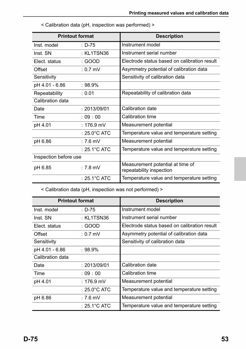
< Calibration data (pH, inspection was performed) >
< Calibration data (pH, inspection was not performed) >
Printout format Description
Inst. model : D-75 Instrument model
Inst. SN : KL1TSN36 Instrument serial number
Elect. status : GOOD Electrode status based on calibration result
Offset : 0.7 mV Asymmetry potential of calibration data
Sensitivity Sensitivity of calibration data
pH 4.01 - 6.86 : 98.9%
Repeatability : 0.01 Repeatability of calibration data
Calibration data
Date : 2013/09/01 Calibration date
Time : 09 : 00 Calibration time
pH 4.01 : 176.9 mV Measurement potential
: 25.0°C ATC Temperature value and temperature setting
pH 6.86 : 7.6 mV Measurement potential
: 25.1°C ATC Temperature value and temperature setting
Inspection before use
pH 6.85 : 7.8 mVMeasurement potential at time of repeatability inspection
: 25.1°C ATC Temperature value and temperature setting
Printout format Description
Inst. model : D-75 Instrument model
Inst. SN : KL1TSN36 Instrument serial number
Elect. status : GOOD Electrode status based on calibration result
Offset : 0.7 mV Asymmetry potential of calibration data
Sensitivity Sensitivity of calibration data
pH 4.01 - 6.86 : 98.9%
Calibration data
Date : 2013/09/01 Calibration date
Time : 09 : 00 Calibration time
pH 4.01 : 176.9 mV Measurement potential
: 25.0°C ATC Temperature value and temperature setting
pH 6.86 : 7.6 mV Measurement potential
: 25.1°C ATC Temperature value and temperature setting

Printing measured values and calibration data
54 HORIBA
< Inspection data (pH) >
Printout format Description
Inst. model : D-75 Instrument model
Inst. SN : KL1TSN36 Instrument serial number
Calibration data
Date : 2013/09/01 Calibration date
Time : 09 : 00 Calibration time
Inspection before use
Repeatability : 0.01 Repeatability of calibration data
pH 6.85 : 7.8 mVMeasurement potential at time of repeatability inspection
: 25.1°C ATC Temperature value and temperature setting
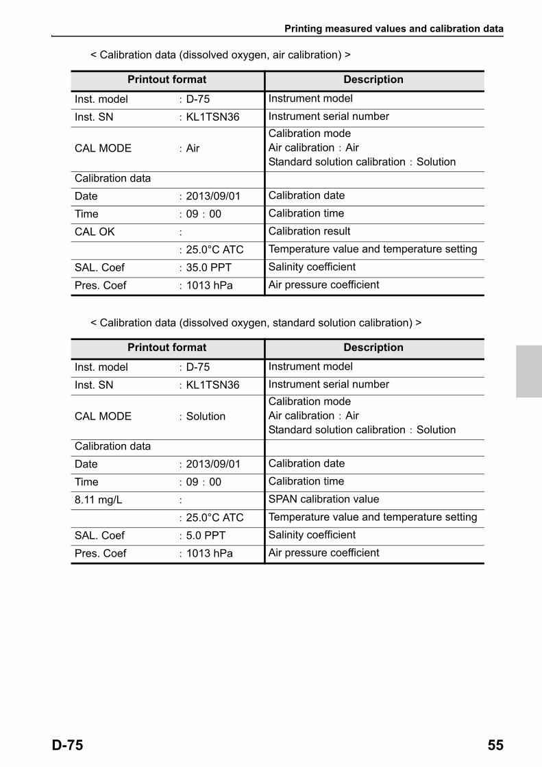
Printing measured values and calibration data
D-75 55
< Calibration data (dissolved oxygen, air calibration) >
< Calibration data (dissolved oxygen, standard solution calibration) >
Printout format Description
Inst. model : D-75 Instrument model
Inst. SN : KL1TSN36 Instrument serial number
CAL MODE : AirCalibration modeAir calibration : AirStandard solution calibration : Solution
Calibration data
Date : 2013/09/01 Calibration date
Time : 09 : 00 Calibration time
CAL OK : Calibration result
: 25.0°C ATC Temperature value and temperature setting
SAL. Coef : 35.0 PPT Salinity coefficient
Pres. Coef : 1013 hPa Air pressure coefficient
Printout format Description
Inst. model : D-75 Instrument model
Inst. SN : KL1TSN36 Instrument serial number
CAL MODE : SolutionCalibration modeAir calibration : AirStandard solution calibration : Solution
Calibration data
Date : 2013/09/01 Calibration date
Time : 09 : 00 Calibration time
8.11 mg/L : SPAN calibration value
: 25.0°C ATC Temperature value and temperature setting
SAL. Coef : 5.0 PPT Salinity coefficient
Pres. Coef : 1013 hPa Air pressure coefficient
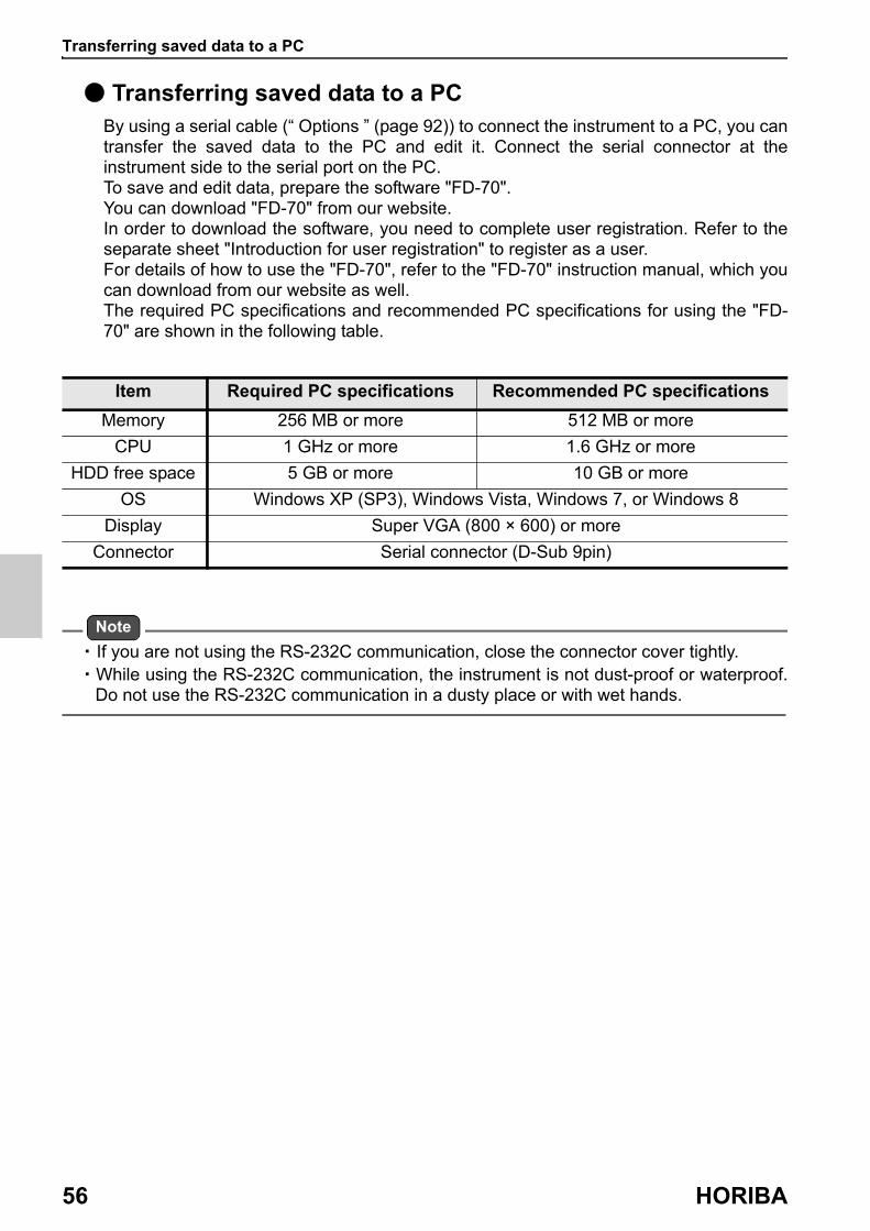
Transferring saved data to a PC
56 HORIBA
● Transferring saved data to a PCBy using a serial cable (“ Options ” (page 92)) to connect the instrument to a PC, you can transfer the saved data to the PC and edit it. Connect the serial connector at the instrument side to the serial port on the PC.To save and edit data, prepare the software "FD-70".You can download "FD-70" from our website.In order to download the software, you need to complete user registration. Refer to the separate sheet "Introduction for user registration" to register as a user.For details of how to use the "FD-70", refer to the "FD-70" instruction manual, which you can download from our website as well.The required PC specifications and recommended PC specifications for using the "FD- 70" are shown in the following table.
Note
・ If you are not using the RS-232C communication, close the connector cover tightly.・ While using the RS-232C communication, the instrument is not dust-proof or waterproof.
Do not use the RS-232C communication in a dusty place or with wet hands.
Item Required PC specifications Recommended PC specifications
Memory 256 MB or more 512 MB or more
CPU 1 GHz or more 1.6 GHz or more
HDD free space 5 GB or more 10 GB or more
OS Windows XP (SP3), Windows Vista, Windows 7, or Windows 8
Display Super VGA (800 × 600) or more
Connector Serial connector (D-Sub 9pin)

Operating the instrument from an external device
D-75 57
● Operating the instrument from an external deviceYou can remotely operate the instrument from an external device (ex.PC) via the RS- 232C communication. Use the serial cable to connect the serial connector on the instrument side and the serial port on the PC.
When using this function, pay attention to the following points.
・ Use the optional serial cable to connect the unit to a PC (“ Options ” (page 92)).
・ Make sure that the transfer formats used in the instrument and a PC are the same. When different transfer formats are used, a communication error occurs and the online mode does not start up, and as a result RS-232C communication cannot be performed. Also, when the transfer format is changed, turn OFF the power of the instrument and PC and then reboot them.
The transfer format of the instrument is as follows. ・ Baud rate: 2400 bps ・ Character length: 8 bits ・ Parity: None ・ Stop bit: 1 bit
You can download a list of communication commands from our website.In order to download the list, you need to complete user registration. Refer to the separate sheet "Introduction for user registration" to register as a user.
Note
・ If you are not using the RS-232C communication, close the connector cover tightly.・ While using the RS-232C communication, the instrument is not dust-proof or waterproof.
Do not use the RS-232C communication in a dusty place or with wet hands.
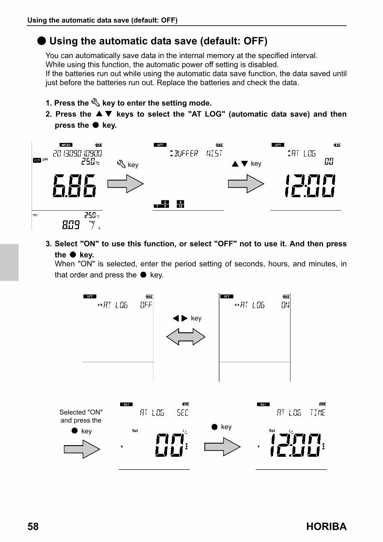
Using the automatic data save (default: OFF)
58 HORIBA
● Using the automatic data save (default: OFF)You can automatically save data in the internal memory at the specified interval.While using this function, the automatic power off setting is disabled.If the batteries run out while using the automatic data save function, the data saved until just before the batteries run out. Replace the batteries and check the data.
1. Press the key to enter the setting mode.
2. Press the keys to select the "AT LOG" (automatic data save) and then
press the key.
3. Select "ON" to use this function, or select "OFF" not to use it. And then press
the key.When "ON" is selected, enter the period setting of seconds, hours, and minutes, in
that order and press the key.
key key
key
key
Selected "ON" and press the
key

Using the automatic data save (default: OFF)
D-75 59
4. Press the key to enter the measurement mode.When this setting is "ON", "AUTO LOG", which indicates that the automatic data save function is on, is displayed.
5. Pressing the key starts saving the data (when the setting is "ON").
Pressing the key again stops the data saving process. During automatic data saving measurement, data is displayed for one second each time a measurement takes place. When more than 1000 data items are saved, "ERR No. 0010" is displayed and data saving is stopped. When you delete the data, the error is cleared (“ Deleting all saved data ” (page 46)).
When data is saved key

Setting the ID number (default: 000)
60 HORIBA
● Setting the ID number (default: 000)You can set an ID number to differentiate the sample of the data to be saved.When the data is saved in the internal memory, the ID number entered in this setting is saved together with the data.
1. Press the key to enter the setting mode.
2. Press the keys to select the "ID" (ID number setting) and then press the key.
3. Enter the ID number to set and press the key.The setting range is 000 to 2999.
key key

Using the calibration interval alarm (default: OFF)
D-75 61
● Using the calibration interval alarm (default: OFF)If calibration has not been performed in pH measurement or calibration has not been performed for a certain period of time after calibration is performed, "ERR No. 0008" is displayed to prevent forgetting to perform calibration.When calibration data is deleted with this function set, an error is displayed immediately.When the error is displayed, performing calibration clears the error.
1. Press the key to enter the setting mode.
2. Press the keys to select the "PERIOD" (calibration interval setting) and
then press the key.
3. Select "ON" to use this function, or select "OFF" not to use it. And then press
the key.When "ON" is selected, enter the setting period of the calibration interval alarm and
then press the key.The setting range is 1 day to 400 days.
key key
key
Selected "ON" and press the
key
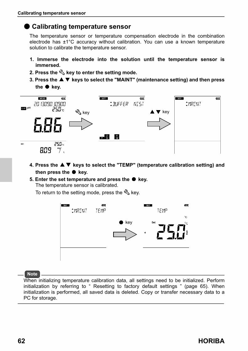
Calibrating temperature sensor
62 HORIBA
● Calibrating temperature sensorThe temperature sensor or temperature compensation electrode in the combination electrode has ±1°C accuracy without calibration. You can use a known temperature solution to calibrate the temperature sensor.
1. Immerse the electrode into the solution until the temperature sensor is immersed.
2. Press the key to enter the setting mode.
3. Press the keys to select the "MAINT" (maintenance setting) and then press
the key.
4. Press the keys to select the "TEMP" (temperature calibration setting) and
then press the key.
5. Enter the set temperature and press the key.The temperature sensor is calibrated.
To return to the setting mode, press the key.
Note
When initializing temperature calibration data, all settings need to be initialized. Perform initialization by referring to “ Resetting to factory default settings ” (page 65). When initialization is performed, all saved data is deleted. Copy or transfer necessary data to a PC for storage.
key key
key

Changing the automatic power off setting (default: OFF)
D-75 63
● Changing the automatic power off setting (default: OFF)You can set the instrument to automatically turn OFF when there is no key operation for a certain period of time.This function is disabled during automatic data memory saving or remote operation using an external device.
1. Press the key to enter the setting mode.
2. Press the keys to select the "MAINT" (maintenance setting) and then press
the key.
3. Press the keys to select the "AT OFF" (automatic power off setting) and
then press the key.4. Select "ON" to use this function, or select "OFF" not to use it. And then press
the key.
When "ON" is selected, enter the automatic power off time and press the key.The setting range is 1 min to 30 min.
To return to the setting mode, press the key.
key key
key key
Selected "ON" and press the
key

Performing test printing of the printer unit
64 HORIBA
● Performing test printing of the printer unitIn order to check whether the printer unit is operating correctly or there is a printer communication problem, you can perform test printing. Connect the instrument and a printer correctly and perform the following procedure for test printing. As a result of test printing, if the printout is as shown below, the printer unit is operating correctly.
1. Press the key to enter the setting mode.
2. Press the keys to select the "MAINT" (maintenance setting) and then press
the key.
3. Press the keys to select the "PRINT" (test print) and then press the key.Printing starts automatically. The printer icon blinks during printing. When printing
ends, the printer icon lights and "END" appears. Press the key.
To return to the setting mode, press the key.
key key
key Printed

Resetting to factory default settings
D-75 65
● Resetting to factory default settingsThe instrument settings can be reset to the factory default settings. The calibration data is deleted but the data of date and time, and the saved data are not deleted. Make sure there will be no problems before using this function. When this function is used, the temperature calibration data is also initialized.
1. Press the key to enter the setting mode.
2. Press the keys to select the "MAINT" (maintenance setting) and then press
the key.
3. Press the keys to select the "INIT" (initialize) and then press the key.4. Select "YES" to initialize the settings to the factory default settings, or select
"NO" to cancel initialization. And then press the key.
When "YES" is selected, "END" appears after the settings are initialized. Press the key.
To return to the setting mode, press the key.
key key
key key
Selected "YES" and press the
key

M E M O
66 HORIBA

Maintenance and storage of the instrument
D-75 67
MaintenanceThis section describes maintenance of the instrument and the electrodes that are used with the instrument. To use them for a long period, perform the described maintenance procedures appropriately.
● Maintenance and storage of the instrument
・ If the instrument becomes dirty, wipe it gently with a soft dry cloth. If it is difficult to remove the dirt, wipe it gently with a cloth moistened with alcohol.
・ The instrument is made of solvent resistant materials but that does not mean it is resistant to all chemicals. Do not dip the instrument in strong acid or alkali solution, or wipe it with such solution.
・ Do not wipe the instrument with a polishing powder or other abrasive compound.
● Environmental conditions for storage
Temperature: 0°C to 45°C Humidity: under 80% in relative humidity and free from condensation
Avoid the following conditions. ・ Dusty place ・ Strong vibration ・ Direct sunlight ・ Corrosive gas environment ・ Close to an air-conditioner ・ Direct wind
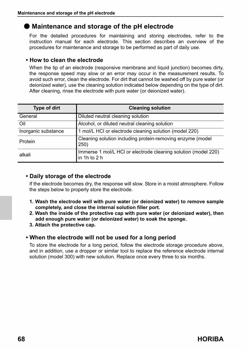
Maintenance and storage of the pH electrode
68 HORIBA
● Maintenance and storage of the pH electrodeFor the detailed procedures for maintaining and storing electrodes, refer to the instruction manual for each electrode. This section describes an overview of the procedures for maintenance and storage to be performed as part of daily use.
• How to clean the electrodeWhen the tip of an electrode (responsive membrane and liquid junction) becomes dirty, the response speed may slow or an error may occur in the measurement results. To avoid such error, clean the electrode. For dirt that cannot be washed off by pure water (or deionized water), use the cleaning solution indicated below depending on the type of dirt. After cleaning, rinse the electrode with pure water (or deionized water).
• Daily storage of the electrodeIf the electrode becomes dry, the response will slow. Store in a moist atmosphere. Follow the steps below to properly store the electrode.
1. Wash the electrode well with pure water (or deionized water) to remove sample completely, and close the internal solution filler port.
2. Wash the inside of the protective cap with pure water (or deionized water), then add enough pure water (or deionized water) to soak the sponge.
3. Attach the protective cap.
• When the electrode will not be used for a long periodTo store the electrode for a long period, follow the electrode storage procedure above, and in addition, use a dropper or similar tool to replace the reference electrode internal solution (model 300) with new solution. Replace once every three to six months.
Type of dirt Cleaning solution
General Diluted neutral cleaning solution
Oil Alcohol, or diluted neutral cleaning solution
Inorganic substance 1 mol/L HCl or electrode cleaning solution (model 220)
ProteinCleaning solution including protein-removing enzyme (model 250)
alkaliImmerse 1 mol/L HCl or electrode cleaning solution (model 220) in 1h to 2 h

Maintenance and storage of the ORP electrode
D-75 69
● Maintenance and storage of the ORP electrodeFor the detailed procedures for maintaining and storing electrodes, refer to the instruction manual for each electrode. This section describes an overview of the procedures for maintenance and storage to be performed as part of daily use.
• How to clean the electrodeWhen the tip of an electrode (responsive membrane and liquid junction) becomes dirty, the response speed may slow or an error may occur in the measurement results. To avoid such error, clean the electrode. For dirt that cannot be washed off by pure water (or deionized water), use the cleaning solution indicated below depending on the type of dirt. After cleaning, rinse the electrode with pure water (or deionized water).
• Daily storage of the electrodeIf the electrode becomes dry, the response will slow. Store in a moist atmosphere. Follow the steps below to properly store the electrode.
1. Wash the electrode well with pure water (or deionized water) to remove sample completely, and close the internal solution filler port.
2. Wash the inside of the protective cap with pure water (or deionized water), then add enough pure water (or deionized water) to soak the sponge.
3. Attach the protective cap.
• When the electrode will not be used for a long periodTo store the electrode for a long period, follow the electrode storage procedure above, and in addition, use a dropper or similar tool to replace the reference electrode internal solution (model 300) with new solution. Replace once every three to six months.
Type of dirt Cleaning solution
GeneralDiluted neutral cleaning solution
Oil
Inorganic substance Immerse dilute nitric acid (1:1 nitric acid)
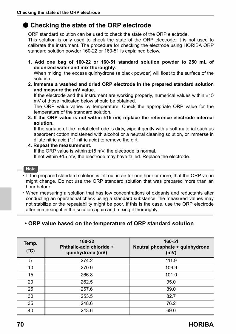
Checking the state of the ORP electrode
70 HORIBA
● Checking the state of the ORP electrodeORP standard solution can be used to check the state of the ORP electrode.This solution is only used to check the state of the ORP electrode; it is not used to calibrate the instrument. The procedure for checking the electrode using HORIBA ORP standard solution powder 160-22 or 160-51 is explained below.
1. Add one bag of 160-22 or 160-51 standard solution powder to 250 mL of deionized water and mix thoroughly.When mixing, the excess quinhydrone (a black powder) will float to the surface of the solution.
2. Immerse a washed and dried ORP electrode in the prepared standard solution and measure the mV value.If the electrode and the instrument are working properly, numerical values within ±15 mV of those indicated below should be obtained.The ORP value varies by temperature. Check the appropriate ORP value for the temperature of the standard solution.
3. If the ORP value is not within ±15 mV, replace the reference electrode internal solution.If the surface of the metal electrode is dirty, wipe it gently with a soft material such as absorbent cotton moistened with alcohol or a neutral cleaning solution, or immerse in dilute nitric acid (1:1 nitric acid) to remove the dirt.
4. Repeat the measurement. If the ORP value is within ±15 mV, the electrode is normal.If not within ±15 mV, the electrode may have failed. Replace the electrode.
Note
・ If the prepared standard solution is left out in air for one hour or more, that the ORP value might change. Do not use the ORP standard solution that was prepared more than an hour before.
・ When measuring a solution that has low concentrations of oxidants and reductants after conducting an operational check using a standard substance, the measured values may not stabilize or the repeatability might be poor. If this is the case, use the ORP electrode after immersing it in the solution again and mixing it thoroughly.
• ORP value based on the temperature of ORP standard solution
Temp.
(°C)
160-22Phthalic-acid chloride +
quinhydrone (mV)
160-51Neutral phosphate + quinhydrone
(mV)
5 274.2 111.9
10 270.9 106.9
15 266.8 101.0
20 262.5 95.0
25 257.6 89.0
30 253.5 82.7
35 248.6 76.2
40 243.6 69.0
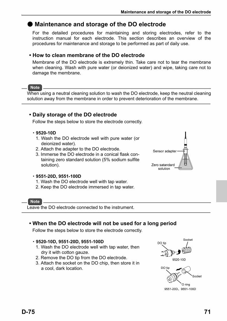
Maintenance and storage of the DO electrode
D-75 71
● Maintenance and storage of the DO electrodeFor the detailed procedures for maintaining and storing electrodes, refer to the instruction manual for each electrode. This section describes an overview of the procedures for maintenance and storage to be performed as part of daily use.
• How to clean membrane of the DO electrodeMembrane of the DO electrode is extremely thin. Take care not to tear the membrane when cleaning. Wash with pure water (or deionized water) and wipe, taking care not to damage the membrane.
Note
When using a neutral cleaning solution to wash the DO electrode, keep the neutral cleaning solution away from the membrane in order to prevent deterioration of the membrane.
• Daily storage of the DO electrodeFollow the steps below to store the electrode correctly.
・ 9520-10D1. Wash the DO electrode well with pure water (or
deionized water).2. Attach the adapter to the DO electrode.3. Immerse the DO electrode in a conical flask con-
taining zero standard solution (5% sodium sulfite solution).
・ 9551-20D, 9551-100D1. Wash the DO electrode well with tap water.2. Keep the DO electrode immersed in tap water.
Note
Leave the DO electrode connected to the instrument.
• When the DO electrode will not be used for a long periodFollow the steps below to store the electrode correctly.
・ 9520-10D, 9551-20D, 9551-100D1. Wash the DO electrode well with tap water, then
dry it with cotton gauze.2. Remove the DO tip from the DO electrode.3. Attach the socket on the DO chip, then store it in
a cool, dark location.
M E M O
72 HORIBA
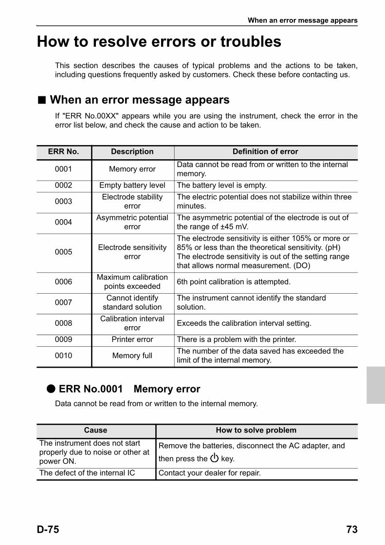
When an error message appears
D-75 73
How to resolve errors or troublesThis section describes the causes of typical problems and the actions to be taken, including questions frequently asked by customers. Check these before contacting us.
■ When an error message appearsIf "ERR No.00XX" appears while you are using the instrument, check the error in the error list below, and check the cause and action to be taken.
● ERR No.0001 Memory errorData cannot be read from or written to the internal memory.
ERR No. Description Definition of error
0001 Memory errorData cannot be read from or written to the internal memory.
0002 Empty battery level The battery level is empty.
0003Electrode stability
errorThe electric potential does not stabilize within three minutes.
0004Asymmetric potential
errorThe asymmetric potential of the electrode is out of the range of ±45 mV.
0005Electrode sensitivity
error
The electrode sensitivity is either 105% or more or 85% or less than the theoretical sensitivity. (pH)The electrode sensitivity is out of the setting range that allows normal measurement. (DO)
0006Maximum calibration
points exceeded6th point calibration is attempted.
0007Cannot identify
standard solutionThe instrument cannot identify the standard solution.
0008Calibration interval
errorExceeds the calibration interval setting.
0009 Printer error There is a problem with the printer.
0010 Memory fullThe number of the data saved has exceeded the limit of the internal memory.
Cause How to solve problem
The instrument does not start properly due to noise or other at power ON.
Remove the batteries, disconnect the AC adapter, and
then press the key.
The defect of the internal IC Contact your dealer for repair.

When an error message appears
74 HORIBA
● ERR No.0002 Empty battery levelThe instrument cannot operate properly because the battery level is empty.
● ERR No.0003 Electrode stability errorDetected an electrode error because the electrical potential does not stabilize after 3 or more minutes during measurement or calibration.
● ERR No.0004 Asymmetric potential errorDetected that the asymmetric potential of the electrode is out of the setting range that allows proper measurement.
Cause How to solve problem
The battery level is empty. Replace the batteries or connect the AC adapter (option).
Cause How to solve problem
The stability of electrode is affected by the sample solution. (The sample solution is solution with low conductivity, or the pH concentration or temperature change).
Read the value without using the automatic hold function.
The electrode is dirty. Clean the electrode.
The electrode is cracked. Replace the electrode.
The responsive glass membrane of the electrode has been dry for a long period.
Immerse the responsive glass membrane of the electrode in pure water (or deionized water) for 24 hours.
The temperature of the sample solution is fluctuating.
Measure the sample solution after its temperature stabilizes.
Cause How to solve problem
The electrode is dirty. Clean the electrode.
The electrode is cracked. Replace the electrode.
The standard solution concentration is fluctuating.
Replace the internal solution in the reference electrode.
The electrode is not connected correctly.
Connect the electrode correctly.
Electrode is not immersed enough to cover liquid junction.
The electrode must be immersed up to the liquid junction.As a guide, immerse to at least 3 cm from the tip of the electrode.
There is a problem with the standard solution.
Use new standard solution.

When an error message appears
D-75 75
● ERR No.0005 Electrode sensitivity error (pH)Detected that the electrode sensitivity is out of the setting range that allows proper measurement.
● ERR No.0005 Electrode sensitivity error (DO)Detected that the electrode sensitivity is out of the setting range that allows normal measurement.
Cause How to solve problem
The electrode is dirty Wash the electrode.
The electrode is cracked Replace the electrode.
Calibration was not performed correctly.
Perform the calibration correctly.
The electrode is not connected correctly
Connect the electrode correctly.
Electrode is not immersed enough to cover liquid junction.
The electrode must be immersed up to the liquid junction.As a guide, immerse to at least 3 cm from the tip of the electrode.
There is a problem with the standard solution.
Use new standard solution.
Cause How to solve problem
The electrode is dirty Wash the electrode.
The electrode is cracked Replace the electrode.
The stirring is inappropriate. Stir at an appropriate stirring speed (1000 to 1500 rpm).
The electrode is not connected correctly
Connect the electrode correctly.
The settings are wrong.Set the correct salinity correction, air pressure correction, and temperature.
There is liquid on the DO tip membrane. (when performing air calibration)
Let the electrode sit until the liquid evaporates or remove the liquid using cotton gauze making sure not to scratch the membrane.
There is something wrong with the standard solution. (when conducting standard solution calibration)
Prepare new zero standard solutions.Sufficiently bubble the span standard solution with a diffuser or other tools.

When an error message appears
76 HORIBA
● ERR No.0006 Maximum calibration points exceededAttempted to perform 6th point calibration during pH calibration.
● ERR No.0007 Cannot identify standard solutionUnable to automatically detect the standard solution during pH calibration.
● ERR No.0008 Calibration interval error
・ More than the set number of days has elapsed since calibration was last performed.・ The calibration interval alarm is "ON" and calibration has not been performed.
Cause How to solve problem
6th point Calibration is attempted.
Up to five points can be calibrated.
Cause How to solve problem
There is a problem with the standard solution.
Use new standard solution.
Settings about the standard solution do not match the instrument.
Check if the instrument settings and the specifications of the standard solution are compatible.
The electrode is dirty. Clean the electrode.
The electrode is cracked. Replace the electrode.
The standard solution concentration is fluctuating.
Replace the internal solution in the reference electrode.
Electrode is not immersed enough to cover liquid junction.
The electrode must be immersed up to the liquid junction.As a guide, immerse to at least 3 cm from the tip of the electrode.
Cause How to solve problem
Calibration has not been performed for the set number of days of the calibration interval or longer.
Perform calibration.
The calibration interval alarm is "ON" and calibration has not been performed.
Perform calibration.

When an error message appears
D-75 77
● ERR No.0009 Printer errorAn error occurred during printer communication.
● ERR No.0010 Memory fullAttempted to save more than 1000 items of data.
Cause How to solve problem
There is a problem with the printer unit connection.
Check the printer connection, and connect the instrument and printer again.
The defect of the printer Consult your dealer.
Cause How to solve problem
Saving more than 1000 items of data is attempted.
The maximum number of savable items of data is 1000. Copy or transfer necessary data to a PC and delete the data from the memory (“ Deleting all saved data ” (page 46)).

Troubleshooting
78 HORIBA
■ TroubleshootingThis section describes causes and actions to take for problems that customers frequently ask us.
● The indicated value fluctuates
< There is a problem with the electrode >
< There is a problem with the instrument >
< There is a problem with the sample >
Cause How to solve problem
The electrode is dirty. Clean the electrode.
The electrode is cracked. Replace the electrode.
The wrong internal solution is being used.
Use the correct internal solution.
There are air bubbles on the electrode.
Shake the electrode to remove the air bubbles.
The level of internal solution in reference electrode is low.
Replenish the internal solution of the reference electrode until it is higher than the level of the sample.
Cause How to solve problem
There is a motor or other device causing electrical interference.
Measure at a place where no influence from induction is given. Ground all AC-powered equipment.
The electrode is not connected correctly.
Connect the electrode correctly.
Cause How to solve problem
Electrode is not immersed enough to cover liquid junction.
The electrode must be immersed up to the liquid junction.As a guide, immerse to at least 3 cm from the tip of the electrode.
The stability of electrode is affected by the sample solution.
It is important to select an electrode that is appropriate for the sample. Consult your dealer. To confirm an electrode that is appropriate for the sample, check the pH electrode selection guide in our catalogue, or refer to our website.
The stirring is inappropriate. Stir at an appropriate stirring speed (1000 to 1500 rpm).

Troubleshooting
D-75 79
● The response is slow
● The indicated value does not change/No response
Cause How to solve problem
The electrode is dirty. Clean the electrode.
The electrode is cracked. Replace the electrode.
The wrong internal solution is being used.
Use the correct internal solution.
The response of electrode is affected by the sample solution.
It is important to select an electrode that is appropriate for the sample. Consult your dealer. To confirm an electrode that is appropriate for the sample, check the pH electrode selection guide in our catalogue, or refer to our website.
Cause How to solve problem
The electrode is cracked. Replace the electrode.
The electrode is not connected correctly.
Connect the electrode correctly.
Keys are locked.Turn off the power, remove the batteries, and then turn on the power again.
The instrument is in HOLD state. Cancel the HOLD state.
Instrument defect Consult your dealer.

Troubleshooting
80 HORIBA
● The measured value blinksThe measured value blinks when it is out of the measurement range.
• How to check for instrument defectShort the metal part of the outer tube to the center pin of the electrode connector of the corresponding channel of the instrument. If the measured value does not blink, the instrument is normal. If the measured value blinks, consult your dealer.
● The temperature display blinks or is fixed at 25°CThe measured value blinks when it is out of the measurement range.
Cause How to solve problem
Sample is out of the measurement range.
Use a sample within the measurement range.
Electrode is not immersed enough to cover liquid junction.
The electrode must be immersed up to the liquid junction.As a guide, immerse to at least 3 cm from the tip of the electrode.
The electrode cable is broken. Replace the electrode.
Calibration is not performed or performed incorrectly.
Perform the calibration correctly.
Instrument defect Check as explained below.
Cause How to solve problem
Sample temperature is out of the measurement range.
Set to a temperature within the measurement range.
Temperature connector is not connected correctly.
Connect the temperature connector correctly.
The temperature setting is set to MTC.
Change the setting to ATC.
Operation is incorrect during temperature calibration.
Recalibrate using a solution of known temperature, or return to the factory setting (“ Resetting to factory default settings ” (page 65)).
Instrument defect Consult your dealer.

Troubleshooting
D-75 81
● Repeatability of the measured value is poor
● Nothing appears when the power is turned ON
● Swelling of operation key sheet
Cause How to solve problem
Effect of the sample solutionRepeatability becomes poor when the pH of the sample changes over time.
The electrode is dirty.Clean the electrode. (Electrode cleaning solution 220 or 250 is recommended.)
The electrode is cracked. Replace the electrode.
The internal solution of the electrode runs out or contaminated.
Replace the internal solution with new one.
The level of internal solution in reference electrode is low.
Replenish the internal solution of the reference electrode until it is higher than the level of the sample.
Cause How to solve problem
Power is not supplied. Insert batteries or connect the AC adapter (option).
Battery polarity (+, ) is reversed.
Insert the batteries with the polarity (+, ) correctly oriented.
Battery life is low. Replace the batteries or connect the AC adapter (option).
Instrument defect Consult your dealer.
Cause How to solve problem
Using the instrument at high elevation or other location where the air pressure is different from sea level.
To eliminate the pressure difference between the inside and outside of the instrument, briefly open and then close the AC adapter cover. After opening, correctly close the cover to maintain dust and water proofing.
Instrument defect Consult your dealer.
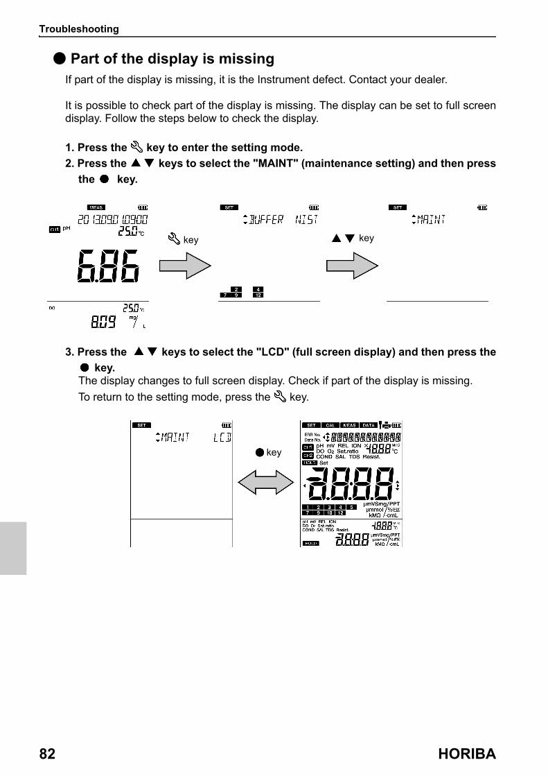
Troubleshooting
82 HORIBA
● Part of the display is missingIf part of the display is missing, it is the Instrument defect. Contact your dealer.
It is possible to check part of the display is missing. The display can be set to full screen display. Follow the steps below to check the display.
1. Press the key to enter the setting mode.
2. Press the keys to select the "MAINT" (maintenance setting) and then press
the key.
3. Press the keys to select the "LCD" (full screen display) and then press the
key.The display changes to full screen display. Check if part of the display is missing.
To return to the setting mode, press the key.
key key
key
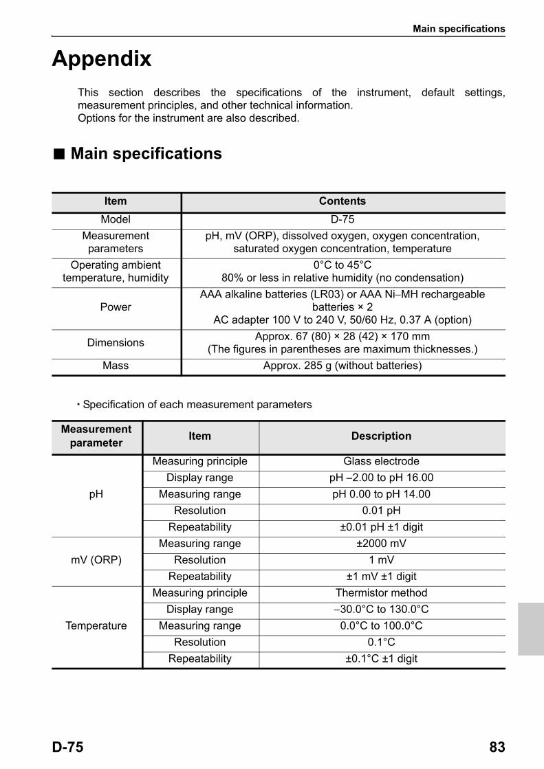
Main specifications
D-75 83
AppendixThis section describes the specifications of the instrument, default settings, measurement principles, and other technical information. Options for the instrument are also described.
■ Main specifications
・Specification of each measurement parameters
Item Contents
Model D-75
Measurement parameters
pH, mV (ORP), dissolved oxygen, oxygen concentration, saturated oxygen concentration, temperature
Operating ambient temperature, humidity
0°C to 45°C80% or less in relative humidity (no condensation)
PowerAAA alkaline batteries (LR03) or AAA NiMH rechargeable
batteries × 2AC adapter 100 V to 240 V, 50/60 Hz, 0.37 A (option)
DimensionsApprox. 67 (80) × 28 (42) × 170 mm
(The figures in parentheses are maximum thicknesses.)
Mass Approx. 285 g (without batteries)
Measurementparameter
Item Description
pH
Measuring principle Glass electrode
Display range pH 2.00 to pH 16.00
Measuring range pH 0.00 to pH 14.00
Resolution 0.01 pH
Repeatability ±0.01 pH ±1 digit
mV (ORP)
Measuring range ±2000 mV
Resolution 1 mV
Repeatability ±1 mV ±1 digit
Temperature
Measuring principle Thermistor method
Display range 30.0°C to 130.0°C
Measuring range 0.0°C to 100.0°C
Resolution 0.1°C
Repeatability ±0.1°C ±1 digit

Instrument default settings
84 HORIBA
■ Instrument default settings
Measurementparameter
Item Description
Dissolved oxygen
Measuring principle Membrane galvanic cell
Measuring range(Display range)
0.00 mg/L to 20.00 mg/L
Resolution 0.01 mg/L
Repeatability ±0.1 mg/L ±1 digit
Oxygen concentration
Measuring principle Conversion from dissolved oxygen value
Measuring range(Display range)
0.0% to 200.0%
Resolution 0.1%
Saturated oxygen
concentration
Measuring principle Conversion from dissolved oxygen value
Measuring range(Display range)
0.0% to 50.0%
Resolution 0.1%
Measurementparameter
ItemSelection item/Setting
rangeDefault values
Common
Temperature settingAutomatic (ATC)/
Manual (MTC)Automatic (ATC)
Temperature input value 0.0°C to 100.0°C 25.0°C
Auto power off ON/OFF OFF
Auto power off time 1 min to 30 min 30 min
Sample ID 000 to 2999 000
Auto data memory ON/OFF OFF
Auto data memory time 2 seconds to 24 hours 2 seconds
pH
Standard solution NIST/USA/CUST NIST
Calibration interval alarm
ON/OFF OFF
Calibration interval 1 day to 400 days 1 day
Dissolved oxygen
Salinity correctionSea concentration (SEA)/
numeric settingnumeric setting
Salinity correction value 0.0 PPT to 40.0 PPT 0.0 PPT
Air pressure value 100 hPa to 1999 hPa 1013 hPa
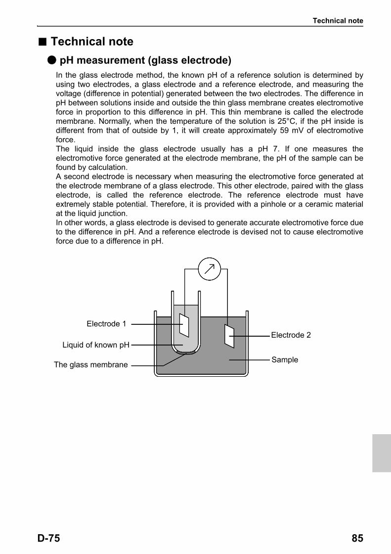
Technical note
D-75 85
■ Technical note
● pH measurement (glass electrode)In the glass electrode method, the known pH of a reference solution is determined by using two electrodes, a glass electrode and a reference electrode, and measuring the voltage (difference in potential) generated between the two electrodes. The difference in pH between solutions inside and outside the thin glass membrane creates electromotive force in proportion to this difference in pH. This thin membrane is called the electrode membrane. Normally, when the temperature of the solution is 25°C, if the pH inside is different from that of outside by 1, it will create approximately 59 mV of electromotive force.The liquid inside the glass electrode usually has a pH 7. If one measures the electromotive force generated at the electrode membrane, the pH of the sample can be found by calculation.A second electrode is necessary when measuring the electromotive force generated at the electrode membrane of a glass electrode. This other electrode, paired with the glass electrode, is called the reference electrode. The reference electrode must have extremely stable potential. Therefore, it is provided with a pinhole or a ceramic material at the liquid junction.In other words, a glass electrode is devised to generate accurate electromotive force due to the difference in pH. And a reference electrode is devised not to cause electromotive force due to a difference in pH.
Electrode 1
Liquid of known pH
The glass membrane
Electrode 2
Sample
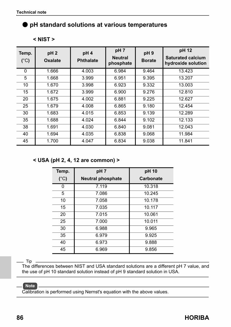
Technical note
86 HORIBA
● pH standard solutions at various temperatures
< NIST >
< USA (pH 2, 4, 12 are common) >
TipThe differences between NIST and USA standard solutions are a different pH 7 value, and the use of pH 10 standard solution instead of pH 9 standard solution in USA.
Note
Calibration is performed using Nernst's equation with the above values.
Temp.
(°C)
pH 2
Oxalate
pH 4
Phthalate
pH 7
Neutral phosphate
pH 9
Borate
pH 12
Saturated calcium hydroxide solution
0 1.666 4.003 6.984 9.464 13.423
5 1.668 3.999 6.951 9.395 13.207
10 1.670 3.998 6.923 9.332 13.003
15 1.672 3.999 6.900 9.276 12.810
20 1.675 4.002 6.881 9.225 12.627
25 1.679 4.008 6.865 9.180 12.454
30 1.683 4.015 6.853 9.139 12.289
35 1.688 4.024 6.844 9.102 12.133
38 1.691 4.030 6.840 9.081 12.043
40 1.694 4.035 6.838 9.068 11.984
45 1.700 4.047 6.834 9.038 11.841
Temp.
(°C)
pH 7
Neutral phosphate
pH 10
Carbonate
0 7.119 10.318
5 7.086 10.245
10 7.058 10.178
15 7.035 10.117
20 7.015 10.061
25 7.000 10.011
30 6.988 9.965
35 6.979 9.925
40 6.973 9.888
45 6.969 9.856
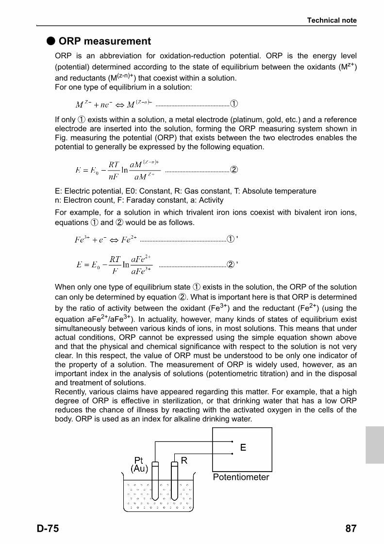
Technical note
D-75 87
● ORP measurementORP is an abbreviation for oxidation-reduction potential. ORP is the energy level
(potential) determined according to the state of equilibrium between the oxidants (Mz+)
and reductants (M(z-n)+) that coexist within a solution.For one type of equilibrium in a solution:
...............................................①
If only ① exists within a solution, a metal electrode (platinum, gold, etc.) and a reference electrode are inserted into the solution, forming the ORP measuring system shown in Fig. measuring the potential (ORP) that exists between the two electrodes enables the potential to generally be expressed by the following equation.
.........................................②
E: Electric potential, E0: Constant, R: Gas constant, T: Absolute temperaturen: Electron count, F: Faraday constant, a: Activity
For example, for a solution in which trivalent iron ions coexist with bivalent iron ions, equations ① and ② would be as follows.
.......................................................① '
...........................................② '
When only one type of equilibrium state ① exists in the solution, the ORP of the solution can only be determined by equation ②. What is important here is that ORP is determined
by the ratio of activity between the oxidant (Fe3+) and the reductant (Fe2+) (using the
equation aFe2+/aFe3+). In actuality, however, many kinds of states of equilibrium exist simultaneously between various kinds of ions, in most solutions. This means that under actual conditions, ORP cannot be expressed using the simple equation shown above and that the physical and chemical significance with respect to the solution is not very clear. In this respect, the value of ORP must be understood to be only one indicator of the property of a solution. The measurement of ORP is widely used, however, as an important index in the analysis of solutions (potentiometric titration) and in the disposal and treatment of solutions. Recently, various claims have appeared regarding this matter. For example, that a high degree of ORP is effective in sterilization, or that drinking water that has a low ORP reduces the chance of illness by reacting with the activated oxygen in the cells of the body. ORP is used as an index for alkaline drinking water.
Potentiometer

Technical note
88 HORIBA
● Dissolved oxygen measurementDissolved oxygen (DO) is the concentration of oxygen that is dissolved in water. DO is essential in the self-cleaning mechanism of rivers and seas and for fish and other aquatic animals. The measurement of DO is also essential for waste-water treatment and water- quality management.The principles of measurement using a DO tip are explained below.
A precious metal (silver) is used as the cathode, which is tightly affixed to an oxygen- permeable membrane, and a base metal (lead) is used as the anode. Both the cathode and anode are immersed in an alkaline electrolytic solution. The external circuit between the anode and cathode is closed. Oxygen that diffuses through the oxygen-permeable membrane causes the following chain reaction to occur in the cathode and allows current to flow in the external circuit.
Whereas, the following oxidation reaction occurs at the anode.
This current is proportional to the amount of oxygen that is diffused through the oxygen- permeable membrane, so measuring the current of the sample enables the DO contained within the sample to be determined. The DO measurement method that is based on this principle is called the “Membrane electrode method.” This is a much simpler and more convenient way of measuring DO than using chemical analysis, which requires complex pretreatment in order to eliminate the effects of reductants and oxidants in the sample.
Anode (lead)
Alkaline electrolyte
Gas-permeable membrane
Electrode
Cathode (silver)
Technical note
D-75 89
● Salinity concentration correctionWhen a solution is in contact with air and is in a state of perfect equilibrium (a state of saturation), the relationship between the DO contained within the solution C (mg/L) and the partial pressure of the oxygen in the air Ps (Mpa) is shown by the following equation.
The H in this equation is referred to as the “Henry constant” and has a different value depending on the composition of the solution. Generally, the higher the salinity concentration within a solution, the larger H becomes, and, consequently, the smaller C becomes.DO tips actually detect the Ps that occurs in the above equation. This means that even if a DO tip is immersed in pure water that is saturated with air or in an aqueous solution containing salt, the output current will not change, which gives rise to a problem.For this reason, it is necessary to correct the salinity concentration, to enable the correct DO to maintain a current, even in an aqueous solution containing salt, and resolve the problem.
● Air pressure correctionThe amount of DO in a solution is proportional to the partial pressure of the oxygen contained within the air in which the solution is in contact. At 25°C, for example, when water is saturated by air that has an atmospheric pressure of 1013 hPa (1 atmosphere), the DO is 8.11 mg/L. As the elevation at which measurement takes place increases, however, the atmospheric pressure caused by the air decreases. So, when air is made to saturate water at a high elevation, where the air pressure is, for example, 506.5 hPa (1/2 atmosphere), the DO will be 4.06 mg/L. As explained above, careful attention must by paid to atmospheric pressure when calibrating a DO meter. Air pressure does not present any special problem when a DO meter is used near sea level, but when it is used at especially high altitudes, it is necessary to correct for the air pressure. This instrument has a built-in air pressure correction function. Set the atmospheric pressure in the instrument when calibrating and the instrument will automatically be calibrated using the air pressure corrected value. Air pressure correction is calculated using the equation below. When calibration is finished, the value derived from this equation is displayed.
Compensated value = × measured value
P: air pressure set in the instrument (hPa)
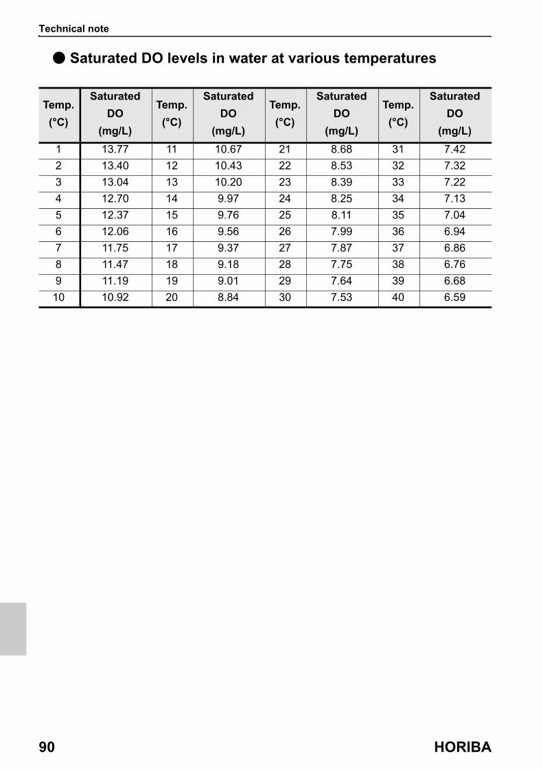
Technical note
90 HORIBA
● Saturated DO levels in water at various temperatures
Temp.
(°C)
Saturated
DO
(mg/L)
Temp.
(°C)
Saturated
DO
(mg/L)
Temp.
(°C)
Saturated
DO
(mg/L)
Temp.
(°C)
Saturated
DO
(mg/L)
1 13.77 11 10.67 21 8.68 31 7.42
2 13.40 12 10.43 22 8.53 32 7.32
3 13.04 13 10.20 23 8.39 33 7.22
4 12.70 14 9.97 24 8.25 34 7.13
5 12.37 15 9.76 25 8.11 35 7.04
6 12.06 16 9.56 26 7.99 36 6.94
7 11.75 17 9.37 27 7.87 37 6.86
8 11.47 18 9.18 28 7.75 38 6.76
9 11.19 19 9.01 29 7.64 39 6.68
10 10.92 20 8.84 30 7.53 40 6.59

For more information
D-75 91
■ For more informationThis manual describes pH measurement, ORP measurement and dissolved oxygen measurement. For detailed information, see "The Story of pH and Water quality" on our website.This page presents the knowhow we have cultivated over many years, for example, how temperature affects measured values and what to do when you want to measure various samples.By registering as a user, you can download sample software, refer to technical documents and receive the newsletter each of which contains useful information on water quality measurement.We look forward to your registration.

Options
92 HORIBA
■ OptionsA wide variety of electrodes and options are available for use with the instrument. You can select the optimum electrode and options for your application and objectives.These options can be purchased from your nearest agency. Please provide the part name and part number to the representative.With regard to electrodes, it is important to select the optimum electrode for the sample you want to measure. For details, refer to the catalogue or our website, or contact your dealer.
Part name Part number Remarks
AC adapter, Cable (UL, 120 V) 3014031951
AC adapter, Cable (EU, 230 V) 3014031952
Plain paperprinter
Printer (USA, 120 V) 3014030146 Printer cable sold separately
Printer (EU, 230 V) 3014030147
Printer cable 3014030148 1.5 m
Roll paper 3014030149 20 rolls/set
Ink ribbon 3014030150 5 pcs/set
Serial cable 3014030151
Electrode stand(model DP-70S)
3200528474
Electrode hook attachment 3200528475
Electrode cleaning solution for low conductivity water or tap water
(model 230)3200530494

2 Miyanohigashi, Kisshoin Minami-ku, Kyoto 601-8510 Japanhttp://www.horiba.com


![Instruction Manual for Ku-band GaN 25W BUC [NJT8370 series] · 2019-03-03 · * Pin G: RS-232C TxD and Pin H: RS-232C RxD are available for only RS-232C Interface M&C models. * Do](https://img.pdfslide.us/doc/110x75/5e98d9fb511fe222e63bf374/instruction-manual-for-ku-band-gan-25w-buc-njt8370-series-2019-03-03-pin-g.jpg)