Embed Size (px)
Citation preview
Hobbico® Model Manufacturing Co. guarantees this kit to be free from defects in both material and workmanship at the date of purchase. This warranty does not cover any component parts damaged by use or modifi cation. In no case shall Hobbico’s liability exceed the original cost of the purchased kit. Further, Hobbico reserves the right to change or modify this warranty without notice.
In that Hobbico has no control over the fi nal assembly or material used for fi nal assembly, no liability shall be assumed nor accepted for any damage resulting from the use by the user of the fi nal user-assembled product. By the act of using the user-assembled product, the user accepts all resulting liability.
If the buyer is not prepared to accept the liability associated with the use of this product, the buyer is advised to return this kit immediately in new and unused condition to the place of purchase.
To make a warranty claim send the defective part or item to Hobby Services at the address below:
Hobby Services3002 N. Apollo Dr., Suite 1Champaign, IL 61822 USA
Include a letter stating your name, return shipping address, as much contact information as possible (daytime telephone number, fax number, e-mail address), a detailed description of the problem and a photocopy of the purchase receipt. Upon receipt of the package, the problem will be evaluated as quickly as possible.
READ THROUGH THIS MANUAL BEFORE STARTING CONSTRUCTION. IT CONTAINS IMPORTANT INSTRUCTIONS AND WARNINGS CONCERNING THE ASSEMBLY AND USE OF THIS MODEL.
Champaign, Illinois(217) 398-8970, Ext 5
E-mail: [email protected]
WARRANTY
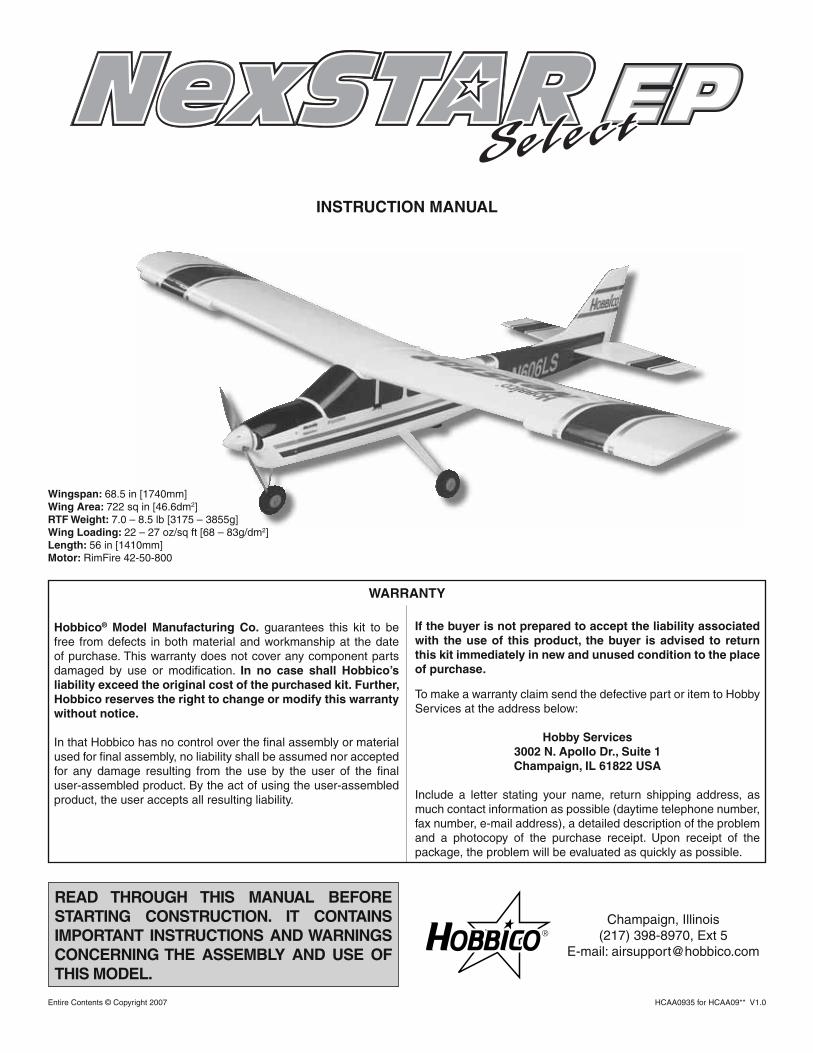
INSTRUCTION MANUAL
Entire Contents © Copyright 2007 HCAA0935 for HCAA09** V1.0
Wingspan: 68.5 in [1740mm] Wing Area: 722 sq in [46.6dm2] RTF Weight: 7.0 – 8.5 lb [3175 – 3855g]Wing Loading: 22 – 27 oz/sq ft [68 – 83g/dm2] Length: 56 in [1410mm]Motor: RimFire 42-50-800
2
TABLE OF CONTENTS
INTRODUCTION ............................................................... 2ACADEMY OF MODEL AERONAUTICS (AMA) .............. 2SPECIFICATION & DESCRIPTION CHANGES ............... 3SAFETY PRECAUTIONS ................................................. 3ADDITIONAL REQUIRED ITEMS .................................... 3 Hardware & Accessories ............................................ 3 Optional Supplies & Tools .......................................... 4ORDERING REPLACEMENT PARTS .............................. 4COMMON ABBREVIATIONS ........................................... 4KIT INSPECTION .............................................................. 5KIT CONTENTS ................................................................ 5A GUIDE TO THE NEXSTAR EP SELECT FEATURES ... 6 Brushless Power System ........................................... 6 CenterCore™ Wing Rib ............................................... 6 SpinControl™ Airfoil Extensions .................................. 6 SpeedBrakes™ Training Flaps .................................... 6 PivotFlex™ Wing Mounting System ............................ 7 EasyAlign™ Tail Mounting System .............................. 7 SnapGear™ Landing Gear .......................................... 7 Futaba® PA-2 Pilot Assist Link ................................... 7 RealFlight® NexStar Edition ....................................... 8ASSEMBLY ....................................................................... 8 Charge the Batteries .................................................. 8 Assemble the Wing .................................................... 9 Install the Landing Gear ........................................... 10 Install the Tail Surfaces ............................................ 10 Install the Motor Batteries ........................................ 11SET-UP ............................................................................ 12 Center the Control Surfaces..................................... 12 Check Control Surface Directions ............................ 14 Arming the Motor ..................................................... 15 Check the Control Throws ........................................ 15 Identify Your Model ................................................... 15 Balance the Model (C.G. - Center of Gravity) .......... 16 Balance the Model Laterally ..................................... 16 Setting Up the Futaba® PA-2 Pilot Assist Link .......... 16 Adjusting the PA-2 from Your Transmitter ................. 19FINAL PREPARATIONS ................................................. 20 Gather the Necessary Tools ..................................... 20 Other Useful Items ................................................... 20 At-The-Shop Check List ........................................... 20FLIGHT PREPARATIONS ............................................... 20 Check the Frequency ............................................... 20 Check the Controls .................................................. 21 Range Check the Radio ........................................... 21FLYING ............................................................................ 21 Taxiing ...................................................................... 21 Takeoff ..................................................................... 21 Flight ........................................................................ 22 Landing .................................................................... 22MAINTENANCE TIPS ..................................................... 22 Covering ................................................................... 22 Propeller ................................................................... 22AFTER YOU MASTER THE NEXSTAR EP SELECTIN ITS ORIGINAL FORM ................................................ 23 SpeedBrakes Training Flaps .................................... 23 SpinControl Airfoil Extensions .................................. 23 Dual Aileron Servos ................................................. 23 Flaperons ................................................................. 24 Dual Aileron Servos & Flaps .................................... 25AMA SAFETY CODE (excerpts) .................................... 26
General .................................................................... 26 Radio Control ........................................................... 26PRE-FLIGHT CHECK LIST ............................................ 26NEXSTAR EP SELECT SUCCESS GUARANTEE ......... 27
INTRODUCTION
Thank you for purchasing the Hobbico NexSTAR™ EP Select, the next generation in Radio Control Trainers. You’ve made the right decision by purchasing a “real” model airplane equipped with a state-of-the-art brushless electric motor, a6-channel radio, the Futaba® PA-2 Pilot Assist Link system, and the latest in aerodynamic and assembly technologies. Once assembled and set up, there will be no fi ddling with a temperamental engine or constant troubleshooting to fi gure out how to get the model to fl y. Under the guidance of an experienced fl ight instructor, all you’ll have to do is concentrate on learning to fl y. And after you’ve mastered the NexSTAR EP Select, the motor, ESC (electronic speed control), and radio system may be transferred to your next model!
We at Hobbico know how exciting a new plane purchase can be and we know you’re anxious to get started, but please take the time to read these instructions before attempting to build and operate your model.
There are three parts to this manual. The fi rst part contains a guide to the unique features of the NexSTAR EP Select, followed by four pages of easy assembly. Lastly, a set-up guide takes you through initial adjustments and fl ight preparation. Do not overlook any of the important set-up procedures and be sure to follow the instructions all the way to the end. Anything skipped in the shop will have to be done at the fi eld anyway.
ACADEMY OF MODELAERONAUTICS (AMA)
If this is your fi rst endeavor in the world of radio-controlled fl ight, we strongly recommend that you join the AMA (Academy of Model Aeronautics) and a local R/C club. The AMA is the governing body of model aviation and membership is required to fl y at AMA clubs. Joining the AMA provides many benefi ts but one of the primary reasons to join is liability protection. The AMA can also direct you to the closest R/C club whose membership includes qualifi ed instructors.
The best thing you can do to insure success is to fi nd a fl ight instructor who will inspect your model for air-worthiness and provide fl ying lessons. It cannot be stated strongly enough that, if you do not already know how to fl y an R/C airplane, you will probably not be able to fl y this model by yourself. It may appear to be easy, but over-controlling and disorientation quickly overcome inexperienced fl iers, swiftly ending their fi rst fl ight. Many have tried to teach themselves, but most become discouraged and end up quitting the hobby, or destroy several models before they are ready to solo.
3
Contact your local hobby shop and ask them to introduce you to an instructor or an R/C club representative. There are over 2,500 AMA chartered clubs across the USA. If there is no club or experienced R/C pilot nearby, it would be worth even a long drive to fi nd one–if only for just a few fl ight lessons (then you’ll have an idea of what to expect). If there is no hobby shop in your area, contact the AMA at the address or toll-free phone number below.
Academy of Model Aeronautics5151 East Memorial Drive
Muncie, IN 47302-9252Tele. (800) 435-9262Fax (765) 741-0057
Or via the Internet at:http://www.modelaircraft.org
Insurance coverage provided by the AMA is not limited to fl ying at contests or on the club fi eld, but even applies to fl ying at public demonstrations and air shows. Failure to comply with the AMA Safety Code (excerpts can be found on page 26 of this manual) may endanger insurance coverage.
IMPORTANT!! Two of the most important things you can do to preserve the radio controlled aircraft hobby are to avoid fl ying near full-scale aircraft and avoid fl ying near or over groups of people.
SPECIFICATION & DESCRIPTION CHANGES
All pictures, descriptions, and specifi cations found in this instruction manual are subject to change without notice. Hobbico maintains no responsibility for inadvertent errors in this manual.
For the latest technical updates or manual corrections for the NexSTAR EP Select, visit the Hobbico web site listed below and select the NexSTAR EP Select. A “Tech Notice” box will appear in the upper left corner of the page if there is new technical information or changes to the kit.
http://www.hobbico.com/airplanes/index.html
PROTECT YOUR MODEL, YOURSELF & OTHERS...FOLLOW THESE
IMPORTANT SAFETY PRECAUTIONS
• Your NexSTAR EP Select should not be considered a toy, but rather a sophisticated, working model that functions very much like a full-size airplane. Because of its performance capabilities, the NexSTAR EP Select, if not assembled and operated properly, could cause injury to yourself, spectators, and/or damage to property.
• You must assemble the model according to the instructions. Do not alter or modify the model, as doing so may result in an unsafe or unfl yable model. In a few cases the instructions may differ slightly from drawings or sketches. In those instances the written instructions should be considered as correct.
• You must check the operation of the model before every fl ight to insure that all equipment is operating and that the model has remained structurally sound. Be sure to check clevises or other connectors often and replace them if they show any signs of wear or fatigue.
• If you are not already an experienced R/C pilot, you should fl y the model only with the help of an experienced R/C pilot.
We, as the kit manufacturer, provide you with a top quality kit and instructions, but ultimately the quality and fl yability of your fi nished model depends on how you build it; therefore, we cannot in any way guarantee the performance of your completed model, and no representations are expressed or implied as to the performance or safety of your completed model.
• Before starting to build, inspect the parts in this kit to make sure that they are of acceptable quality. If any parts are not of acceptable quality, or if you need assistance withassembly, contact:
Hobbico Product SupportPhone: (217) 398-8970, ext. 5
Fax: (217) 398-7721E-mail: [email protected]
If the buyer is not prepared to accept the liability associated with the use of this product, the buyer is advised to return this kit in new and unused condition to the place of purchase.
ADDITIONAL REQUIRED ITEMS
Hardware & Accessories
The following is a list of accessories required to make the NexSTAR EP Select operational. Order numbers are in parentheses.
❏ (2) 8-Cell 9.6V 3600 mAh NiMH (Nickel-Metal Hydride) battery packs (GPMP0362)
❏ Hobbico Dual Peak NiMH Charger (HCAP0255)
The NexSTAR EP Select can also be fl own with a 5-cell Lithium-Polymer (LiPo) set up. If you decide to go with LiPo batteries, you will need the following items:
❏ *2S 3200mAh 7.4V 20C Discharge w/Balance (GPMP0622)❏ *3S 3200mAh 11.1V 20C Discharge w/Balance (GPMP0623)(*Use them together for a 5S set-up)
A cell balancer is highly recommended for the battery packs listed above:
❏ Great Planes Electrifl y™ Equinox™ Cell Balancer 1 to 5 (GPMM3160)
A suitable charger is also required:
The Great Planes PolyCharge4™ (GPMM3015) is designed for LiPo packs only, but is able to charge four LiPo packs simultaneously. The Great Planes Triton™2 (GPMM3153) charger will only charge one pack at a time, but is capable of charging NiCd, NiMH, LiPo and lead acid batteries.
Optional Supplies & Tools
Here is a list of optional tools mentioned in the manual that will help you prepare the NexSTAR EP Select for fl ight.
❏ C.G. Machine™ (GPMR2400)❏ Precision Magnetic Propeller Balancer (TOPQ5700)❏ Stick-On Segmented Lead Weights (GPMQ4485)❏ Top Flite® MonoKote® Sealing Iron (TOPR2100)❏ Top Flite Hot Sock™ Iron Cover (TOPR2175)❏ Robart Super Stand II (ROBP1402)
ORDERING REPLACEMENT PARTS
Replacement parts for the NexSTAR EP Select are available using the order numbers in the Replacement Parts List that follows. The fastest, most economical service can be provided by your hobby dealer or mail-order company.
To locate a hobby dealer, visit the Hobbico web site atwww.hobbico.com. Choose “Where to Buy” at the bottom of the menu on the left side of the page. Follow the instructions provided on the page to locate a U.S., Canadian, or International dealer.
Parts may also be ordered directly from Hobby Services by calling (217) 398-0007 or via facsimile at (217) 398-7721, but full retail prices and shipping and handling charges will apply. Illinois and Nevada residents will also be charged sales tax. If ordering via fax, include a Visa® or MasterCard® number and expiration date for payment.
If ordering via mail, send parts orders and payments by personal check to:
Hobby Services3002 N. Apollo Drive, Suite 1
Champaign, IL 61822
Be certain to specify the order number exactly as listed in the Replacement Parts List and indicate the quantity of each item. Payment accepted by credit card or personal check only;no C.O.D.
If additional assistance is required for any reason, contact Product Support by e-mail at [email protected], or by telephone at (217) 398-8970.
Description How to PurchaseMissing Pieces Contact Product SupportInstruction Manual Contact Product SupportFull-Size Plans Not AvailableKit Parts (see Replacement Parts List) Hobby Supplier
Replacement Parts List
HCAA3770 Wing KitHCAA3771 Fuselage KitHCAA3772 Tail SetHCAA3742 Landing GearHCAA3774 Decal SetAPCQ4120 PropellerGPMQ4515 SpinnerGPMG4700 RimFire Brushless MotorHCAA3773 ESCHCAA3737 Spin Control/SpeedBrakesHCAA3748 Tail Mounting Screw (2)HCAA3745 CenterCore Wing JoinerHCAA3746 PivotFlex Wing BracketHCAA3775 Cowling
WARNING: The motor, ESC, and propeller supplied with the NexSTAR EP Select are a matched set and must be used together. Should you choose to change one or more of the supplied components, you will void your warranty on this product.
COMMON ABBREVIATIONS
Fuse = Fuselage Stab = Horizontal Stabilizer Fin = Vertical Fin or Vertical Stabilizer LE = Leading Edge TE = Trailing Edge LG = Landing Gear " = Inches mm = Millimeters ESC = Electronic Speed Control mAh = Milliamp Hours NiMH = Nickel-Metal Hydride LiPo = Lithium Polymer NiCd = Nickel cadmium Prop = Propeller C.G. = Center of Gravity SHCS = Socket Head Cap Screw
4
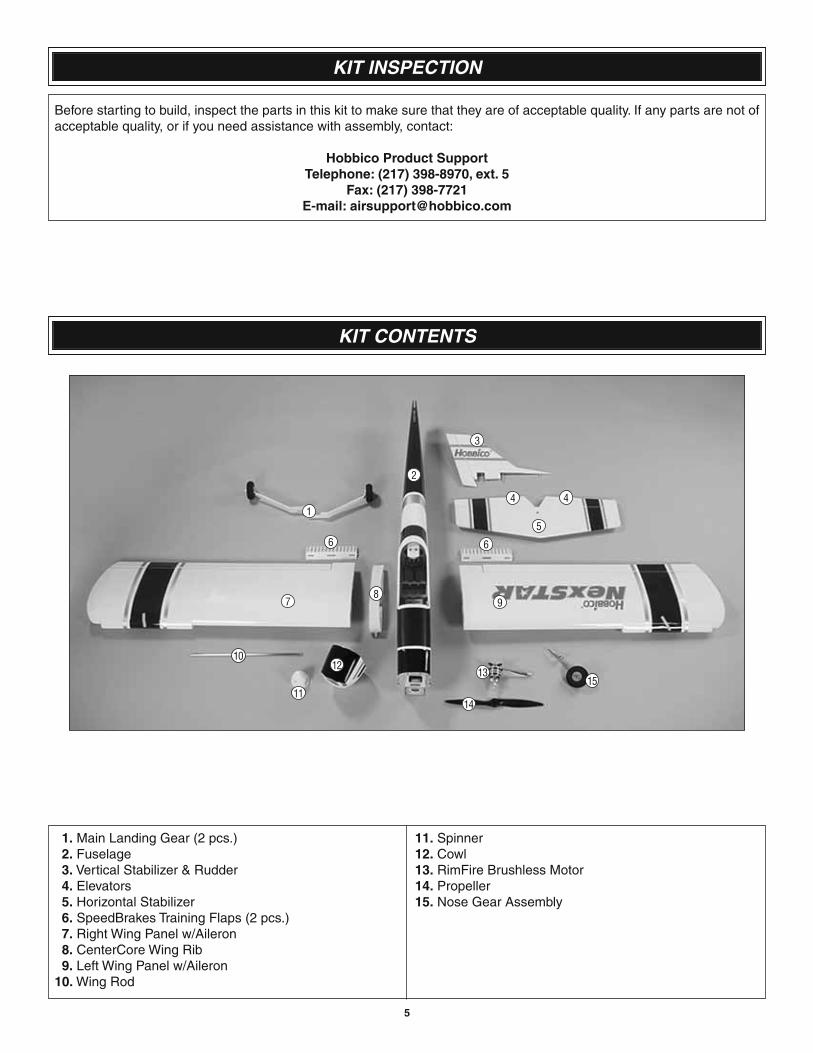
KIT INSPECTION
Before starting to build, inspect the parts in this kit to make sure that they are of acceptable quality. If any parts are not of acceptable quality, or if you need assistance with assembly, contact:
Hobbico Product SupportTelephone: (217) 398-8970, ext. 5
Fax: (217) 398-7721E-mail: [email protected]
1. Main Landing Gear (2 pcs.) 2. Fuselage 3. Vertical Stabilizer & Rudder 4. Elevators 5. Horizontal Stabilizer 6. SpeedBrakes Training Flaps (2 pcs.) 7. Right Wing Panel w/Aileron 8. CenterCore Wing Rib 9. Left Wing Panel w/Aileron 10. Wing Rod
11. Spinner 12. Cowl 13. RimFire Brushless Motor 14. Propeller 15. Nose Gear Assembly
5
KIT CONTENTS
3
2
9
10
5
4
13
1
6
87
4
6
11
12
14
15
6
A GUIDE TO THE NEXSTAR EP SELECT FEATURES
Brushless Power System
Though electric R/C fl ying has been around a long time, brushless motor technology has renewed interest in the hobby for old-timers and sparked a whole new generation of R/C modelers.
The brushless motor used on the NexSTAR EP Select is a Great Planes RimFire™ 42-50-800. Deatils about this motor can be found at www.electrifl y/rimfi re.com.
The electronic speed control (ESC) used on the NexSTAR EP Select is a Great Planes Silver Series SS-55D. This is a 6S LiPo (or 16C NiMH) programmable 55 amp ESC.
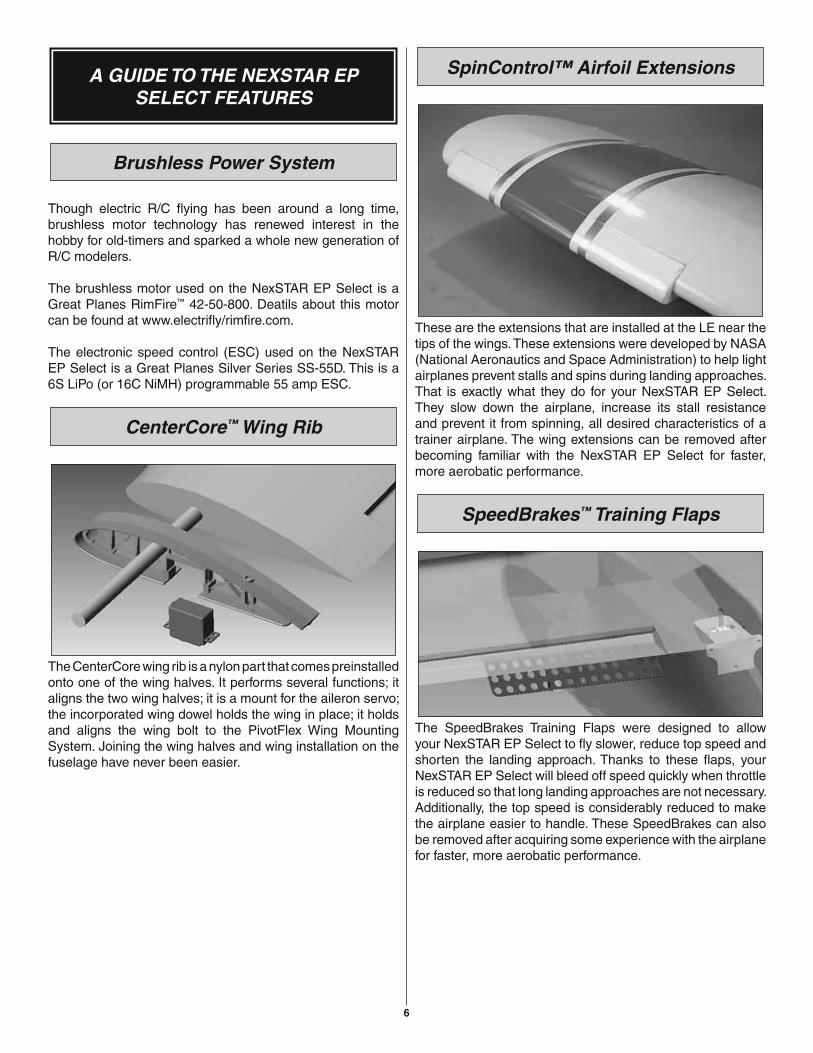
CenterCore™ Wing Rib
The CenterCore wing rib is a nylon part that comes preinstalled onto one of the wing halves. It performs several functions; it aligns the two wing halves; it is a mount for the aileron servo; the incorporated wing dowel holds the wing in place; it holds and aligns the wing bolt to the PivotFlex Wing Mounting System. Joining the wing halves and wing installation on the fuselage have never been easier.
SpinControl™ Airfoil Extensions
These are the extensions that are installed at the LE near the tips of the wings. These extensions were developed by NASA (National Aeronautics and Space Administration) to help light airplanes prevent stalls and spins during landing approaches. That is exactly what they do for your NexSTAR EP Select. They slow down the airplane, increase its stall resistance and prevent it from spinning, all desired characteristics of a trainer airplane. The wing extensions can be removed after becoming familiar with the NexSTAR EP Select for faster, more aerobatic performance.
SpeedBrakes™ Training Flaps
The SpeedBrakes Training Flaps were designed to allow your NexSTAR EP Select to fl y slower, reduce top speed and shorten the landing approach. Thanks to these fl aps, your NexSTAR EP Select will bleed off speed quickly when throttle is reduced so that long landing approaches are not necessary. Additionally, the top speed is considerably reduced to make the airplane easier to handle. These SpeedBrakes can also be removed after acquiring some experience with the airplane for faster, more aerobatic performance.
7
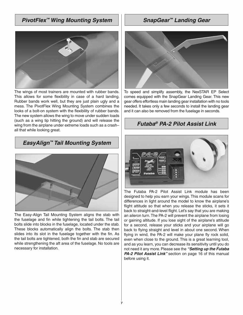
PivotFlex™ Wing Mounting System
The wings of most trainers are mounted with rubber bands. This allows for some fl exibility in case of a hard landing. Rubber bands work well, but they are just plain ugly and a mess. The PivotFlex Wing Mounting System combines the looks of a bolt-on system with the fl exibility of rubber bands. The new system allows the wing to move under sudden loads (such as a wing tip hitting the ground) and will release the wing from the airplane under extreme loads such as a crash–all that while looking great.
EasyAlign™ Tail Mounting System
The Easy-Align Tail Mounting System aligns the stab with the fuselage and fi n while tightening the tail bolts. The tail bolts slide into blocks in the fuselage, located under the stab. These blocks automatically align the bolts. The stab then slides into its slot in the fuselage together with the fi n. As the tail bolts are tightened, both the fi n and stab are secured while strengthening the aft area of the fuselage. No tools are necessary for installation.
SnapGear™ Landing Gear
To speed and simplify assembly, the NexSTAR EP Select comes equipped with the SnapGear Landing Gear. This new gear offers effortless main landing gear installation with no tools needed. It takes only a few seconds to install the landing gear and it can also be removed from the fuselage in seconds.
Futaba® PA-2 Pilot Assist Link
The Futaba PA-2 Pilot Assist Link module has been designed to help you earn your wings. This module scans for differences in light around the model to know the airplane’s fl ight attitude so that when you release the sticks, it sets it back to straight-and-level fl ight. Let’s say that you are making an aileron turn. The PA-2 will prevent the airplane from losing or gaining altitude. If you lose sight of the airplane’s attitude for a second, release your sticks and your airplane will go back to fl ying straight and level in about one second. When fl ying in wind, the PA-2 will make your plane fl y rock solid, even when close to the ground. This is a great learning tool, and as you learn, you can decrease its sensitivity until you do not need it any more. Please see the “Setting up the Futaba PA-2 Pilot Assist Link” section on page 16 of this manual before using it.
8
RealFlight® NexSTAR Edition
On top of the previously mentioned items, there is still one last treat in your NexSTAR EP Select package: A RealFlight NexSTAR EP Edition CD-ROM. RealFlight is the best R/C airplane simulator in the market, and it is a great learning tool. Once installed in your computer, RealFlight will allow you to use your own NexSTAR EP Select Radio Transmitter to fl y your NexSTAR EP Select on your computer. Simulators are great learning tools because they allow you to learn about airplane orientation, fl ying speed, stalling performance, take off and landing, and the whole spectrum of fl ight without any risk. The physics of RealFlight are so close to reality that you will be amazed. The RealFlight NexSTAR EP edition also lets you practice with your transmitter and all the controls in it. Learn to fl y with RealFlight, practice new maneuvers and once you feel confi dent, get out there and enjoy your NexSTAR EP Select.
ASSEMBLY
Charge the Batteries
First, a word about the different batteries associated with this airplane.
Generally, batteries are shipped with a partial or “residual” charge. If you plan to assemble the plane now, this will probably be enough of a charge to set-up your airplane but you will need to give them a full charge before attempting to fl y. This applies to the transmitter, receiver, and motor batteries. If you plan to assemble the plane later, charge the radio system batteries following the instructions in the instruction manual; this is typically an overnight charge.
This would also be a good time to charge the motor batteries. You will need to refer to your charger’s instruction manual for proper charging procedures.
While the batteries are charging, feel free to begin assembling the airplane.
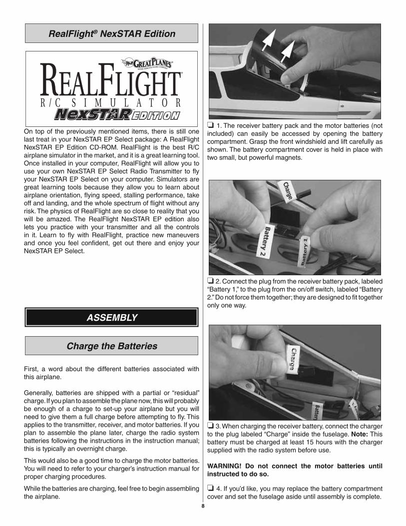
❏ 1. The receiver battery pack and the motor batteries (not included) can easily be accessed by opening the battery compartment. Grasp the front windshield and lift carefully as shown. The battery compartment cover is held in place with two small, but powerful magnets.
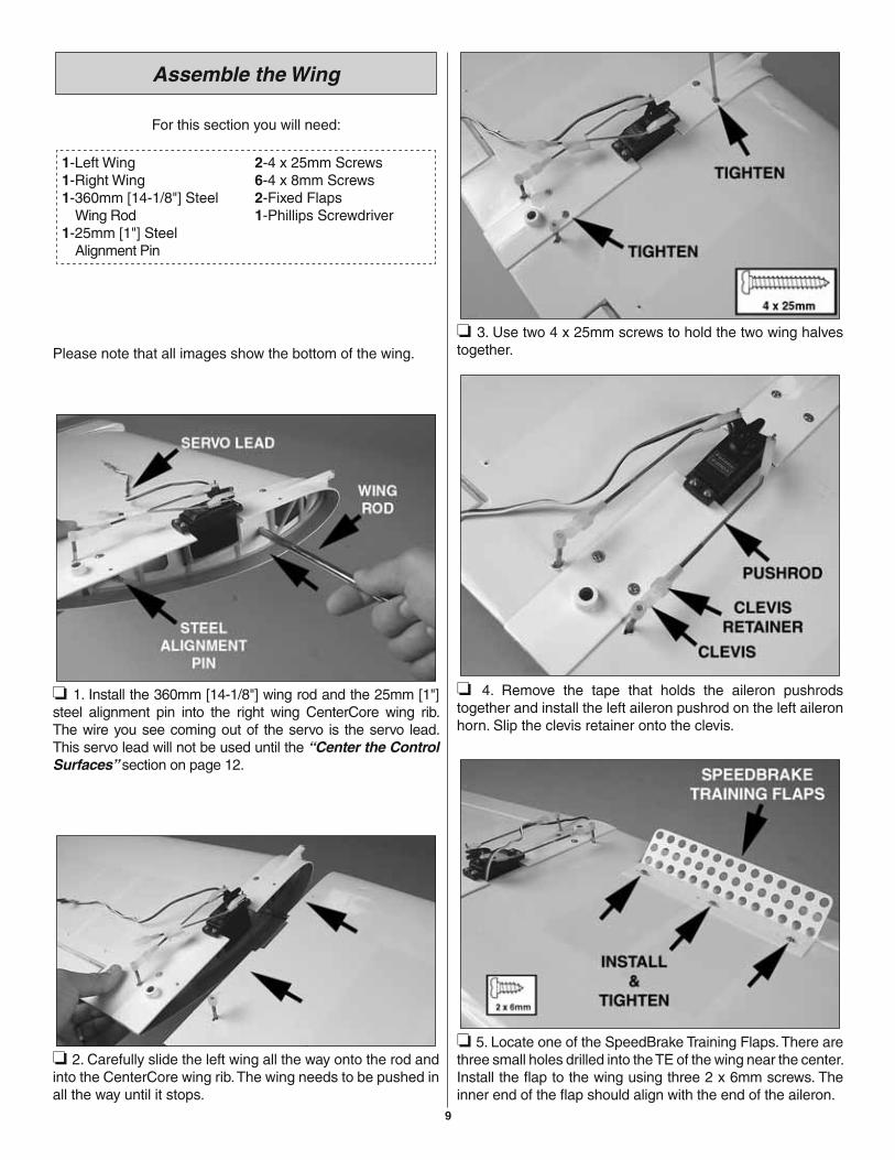
❏ 2. Connect the plug from the receiver battery pack, labeled “Battery 1,” to the plug from the on/off switch, labeled “Battery 2.” Do not force them together; they are designed to fi t together only one way.
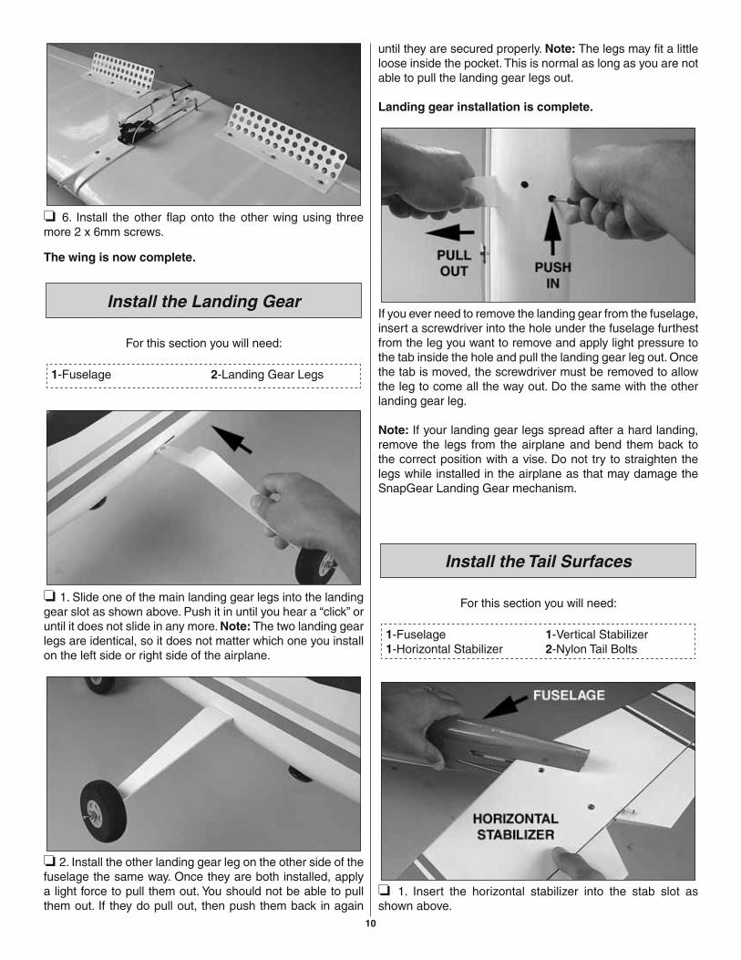
❏ 3. When charging the receiver battery, connect the charger to the plug labeled “Charge” inside the fuselage. Note: This battery must be charged at least 15 hours with the charger supplied with the radio system before use.
WARNING! Do not connect the motor batteries until instructed to do so.
❏ 4. If you’d like, you may replace the battery compartment cover and set the fuselage aside until assembly is complete.
9
Assemble the Wing
For this section you will need:
1-Left Wing1-Right Wing1-360mm [14-1/8"] Steel Wing Rod1-25mm [1"] Steel Alignment Pin
2-4 x 25mm Screws6-4 x 8mm Screws2-Fixed Flaps1-Phillips Screwdriver
Please note that all images show the bottom of the wing.
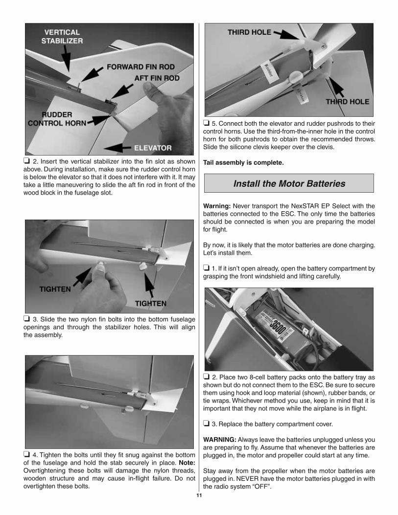
❏ 1. Install the 360mm [14-1/8"] wing rod and the 25mm [1"] steel alignment pin into the right wing CenterCore wing rib. The wire you see coming out of the servo is the servo lead. This servo lead will not be used until the “Center the Control Surfaces” section on page 12.
❏ 2. Carefully slide the left wing all the way onto the rod and into the CenterCore wing rib. The wing needs to be pushed in all the way until it stops.
❏ 3. Use two 4 x 25mm screws to hold the two wing halves together.
❏ 4. Remove the tape that holds the aileron pushrods together and install the left aileron pushrod on the left aileron horn. Slip the clevis retainer onto the clevis.
❏ 5. Locate one of the SpeedBrake Training Flaps. There are three small holes drilled into the TE of the wing near the center. Install the fl ap to the wing using three 2 x 6mm screws. The inner end of the fl ap should align with the end of the aileron.
10
❏ 6. Install the other fl ap onto the other wing using three more 2 x 6mm screws.
The wing is now complete.
Install the Landing Gear
For this section you will need:
1-Fuselage 2-Landing Gear Legs
❏ 1. Slide one of the main landing gear legs into the landing gear slot as shown above. Push it in until you hear a “click” or until it does not slide in any more. Note: The two landing gear legs are identical, so it does not matter which one you install on the left side or right side of the airplane.
❏ 2. Install the other landing gear leg on the other side of the fuselage the same way. Once they are both installed, apply a light force to pull them out. You should not be able to pull them out. If they do pull out, then push them back in again
until they are secured properly. Note: The legs may fi t a little loose inside the pocket. This is normal as long as you are not able to pull the landing gear legs out.
Landing gear installation is complete.
If you ever need to remove the landing gear from the fuselage, insert a screwdriver into the hole under the fuselage furthest from the leg you want to remove and apply light pressure to the tab inside the hole and pull the landing gear leg out. Once the tab is moved, the screwdriver must be removed to allow the leg to come all the way out. Do the same with the other landing gear leg.
Note: If your landing gear legs spread after a hard landing, remove the legs from the airplane and bend them back to the correct position with a vise. Do not try to straighten the legs while installed in the airplane as that may damage the SnapGear Landing Gear mechanism.
Install the Tail Surfaces
For this section you will need:
1-Fuselage1-Horizontal Stabilizer
1-Vertical Stabilizer2-Nylon Tail Bolts
❏ 1. Insert the horizontal stabilizer into the stab slot asshown above.
11
❏ 2. Insert the vertical stabilizer into the fi n slot as shown above. During installation, make sure the rudder control horn is below the elevator so that it does not interfere with it. It may take a little maneuvering to slide the aft fi n rod in front of the wood block in the fuselage slot.
❏ 3. Slide the two nylon fi n bolts into the bottom fuselage openings and through the stabilizer holes. This will alignthe assembly.
❏ 4. Tighten the bolts until they fi t snug against the bottom of the fuselage and hold the stab securely in place. Note: Overtightening these bolts will damage the nylon threads, wooden structure and may cause in-fl ight failure. Do not overtighten these bolts.
❏ 5. Connect both the elevator and rudder pushrods to their control horns. Use the third-from-the-inner hole in the control horn for both pushrods to obtain the recommended throws. Slide the silicone clevis keeper over the clevis.
Tail assembly is complete.
Install the Motor Batteries
Warning: Never transport the NexSTAR EP Select with the batteries connected to the ESC. The only time the batteries should be connected is when you are preparing the model for fl ight.
By now, it is likely that the motor batteries are done charging. Let’s install them.
❏ 1. If it isn’t open already, open the battery compartment by grasping the front windshield and lifting carefully.
❏ 2. Place two 8-cell battery packs onto the battery tray as shown but do not connect them to the ESC. Be sure to secure them using hook and loop material (shown), rubber bands, or tie wraps. Whichever method you use, keep in mind that it is important that they not move while the airplane is in fl ight.
❏ 3. Replace the battery compartment cover.
WARNING: Always leave the batteries unplugged unless you are preparing to fl y. Assume that whenever the batteries are plugged in, the motor and propeller could start at any time.
Stay away from the propeller when the motor batteries are plugged in. NEVER have the motor batteries plugged in with the radio system “OFF”.
12
SET-UP
Now the plane is assembled, but there are a few things that must be done before it will be ready to fl y. You must carefully perform all of the following set-up procedures. If possible, have your fl ight instructor assist.
If you have not yet charged the batteries, you may still proceed. However, as the batteries have not yet been fully charged, they may not provide enough power to make it all the way through the set-up procedures. If the batteries quit working, set your tools aside and charge the batteries as described in the instruction manual for the Futaba radio control system that came with this kit.
The PA-2 Pilot Assist Link device should be unplugged at this point to ensure that the following set-up is successful. The PA-2 Pilot Assist Link unit comes unplugged from the factory.
Center the Control Surfaces
1-1/4-20 Nylon Bolt
The fi rst thing that has to be done is to make sure all the control surfaces are centered.
❏ 1. Connect the aileron servo wire coming from the wing labeled “Aileron A” to the plug in the fuselage labeled “Aileron B” coming from the receiver. Do not force them together; they are designed to fi t together only one way. Temporarily mount the wing to the fuselage with a nylon wing bolt.
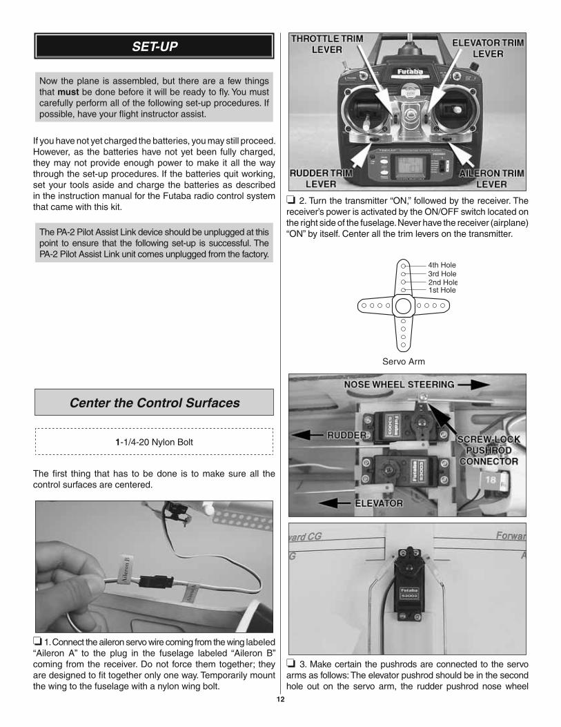
❏ 2. Turn the transmitter “ON,” followed by the receiver. The receiver’s power is activated by the ON/OFF switch located on the right side of the fuselage. Never have the receiver (airplane) “ON” by itself. Center all the trim levers on the transmitter.
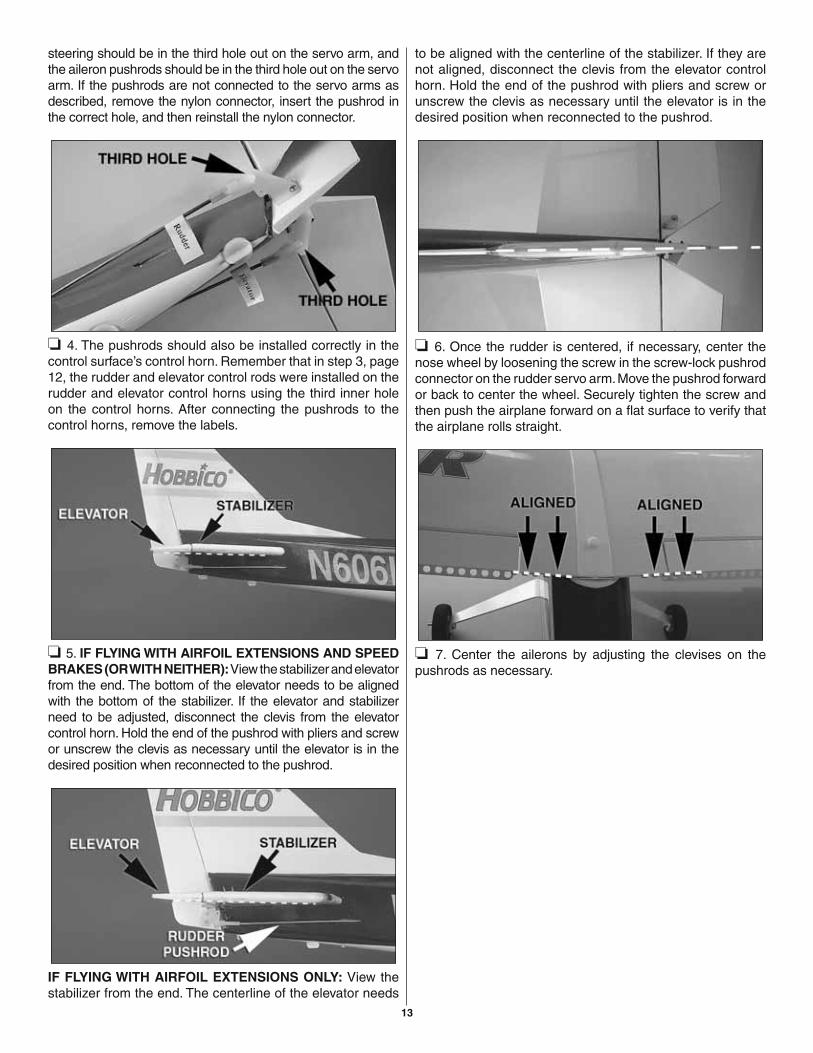
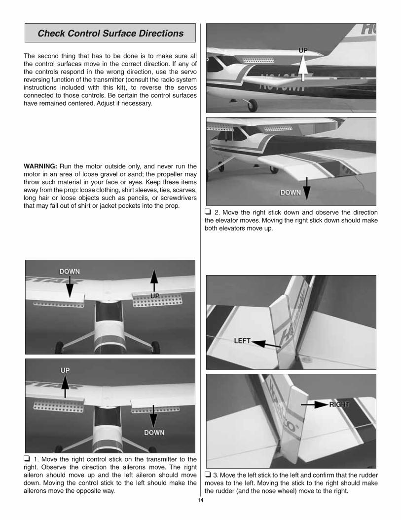
❏ 3. Make certain the pushrods are connected to the servo arms as follows: The elevator pushrod should be in the second hole out on the servo arm, the rudder pushrod nose wheel
13
steering should be in the third hole out on the servo arm, and the aileron pushrods should be in the third hole out on the servo arm. If the pushrods are not connected to the servo arms as described, remove the nylon connector, insert the pushrod in the correct hole, and then reinstall the nylon connector.
❏ 4. The pushrods should also be installed correctly in the control surface’s control horn. Remember that in step 3, page 12, the rudder and elevator control rods were installed on the rudder and elevator control horns using the third inner hole on the control horns. After connecting the pushrods to the control horns, remove the labels.
❏ 5. IF FLYING WITH AIRFOIL EXTENSIONS AND SPEED BRAKES (OR WITH NEITHER): View the stabilizer and elevator from the end. The bottom of the elevator needs to be aligned with the bottom of the stabilizer. If the elevator and stabilizer need to be adjusted, disconnect the clevis from the elevator control horn. Hold the end of the pushrod with pliers and screw or unscrew the clevis as necessary until the elevator is in the desired position when reconnected to the pushrod.
IF FLYING WITH AIRFOIL EXTENSIONS ONLY: View the stabilizer from the end. The centerline of the elevator needs
to be aligned with the centerline of the stabilizer. If they are not aligned, disconnect the clevis from the elevator control horn. Hold the end of the pushrod with pliers and screw or unscrew the clevis as necessary until the elevator is in the desired position when reconnected to the pushrod.
❏ 6. Once the rudder is centered, if necessary, center the nose wheel by loosening the screw in the screw-lock pushrod connector on the rudder servo arm. Move the pushrod forward or back to center the wheel. Securely tighten the screw and then push the airplane forward on a fl at surface to verify that the airplane rolls straight.
❏ 7. Center the ailerons by adjusting the clevises on the pushrods as necessary.
14
Check Control Surface Directions
The second thing that has to be done is to make sure all the control surfaces move in the correct direction. If any of the controls respond in the wrong direction, use the servo reversing function of the transmitter (consult the radio system instructions included with this kit), to reverse the servos connected to those controls. Be certain the control surfaces have remained centered. Adjust if necessary.
WARNING: Run the motor outside only, and never run the motor in an area of loose gravel or sand; the propeller may throw such material in your face or eyes. Keep these items away from the prop: loose clothing, shirt sleeves, ties, scarves, long hair or loose objects such as pencils, or screwdrivers that may fall out of shirt or jacket pockets into the prop.
❏ 1. Move the right control stick on the transmitter to the right. Observe the direction the ailerons move. The right aileron should move up and the left aileron should move down. Moving the control stick to the left should make the ailerons move the opposite way.
❏ 2. Move the right stick down and observe the direction the elevator moves. Moving the right stick down should make both elevators move up.
❏ 3. Move the left stick to the left and confi rm that the rudder moves to the left. Moving the stick to the right should make the rudder (and the nose wheel) move to the right.
15
Note that moving the elevator stick down moves the elevator up (which, in fl ight, pushes the tail down, thus increasing the angle of the wing and making the model climb). The best way to keep this in mind is to think in terms of a pilot in an airplane. He pulls the control stick back to “pull up” the nose of the plane.
Arming the Motor
Before arming the motor, please check the propeller to make sure it is tightened securely. Using a #2 Philips head screwdriver, simply remove the two 3 x 12mm[#4 x 3/8"] screws and remove the spinner cone. Use a 13mm [1/2"] wrench to tighten the prop nut securely (Be careful not to overtighten it). Replace the spinner cone and re-tighten the two 3 x 12mm [#4 x 3/8"] screws.
Note: The ESC will remain armed until you disconnect the motor battery packs.
The ESC provided with the NexSTAR EP Select features a brake function that is useful for some aircraft, but is unnecessary for this model. The factory default setting is “BRAKE OFF” but if you notice that the motor stops abruptly when you shut down the throttle, the ESC will need to be re-programmed. This is something that you can easily do by following these simple steps:
❏ 1. With the power “OFF” to both the transmitter and airplane, move the transmitter throttle stick to full throttle position.
❏ 2. Turn the transmitter “ON,” turn the plane’s receiver “ON”, and then connect the motor batteries to the ESC.
❏ 3. After 5 seconds the motor will beep once.
❏ 4. Move the transmitter throttle stick toward you to the “throttle down” position. The motor will beep once.
❏ 5. Again, move the transmitter throttle stick to full throttle. The motor will beep once more to confi rm the brake is now “OFF.”
Once the brake is set, it does not require resetting after the motor batteries have been disconnected.
Check the Control Throws
The fi nal thing that has to be done is to make sure the controls move the correct amount. The control throws were set-up at the factory, so use the following as a guide to make sure they work correctly.
IMPORTANT: The control throws are a measure of how far the fl ight controls (ailerons, elevator and rudder) move. The NexSTAR EP Select has been extensively fl own and tested to arrive at the throws at which it fl ies best. Flying your model at these throws will provide you with the greatest chance for successful fi rst fl ights. After you have become accustomed to the way the NexSTAR EP Select fl ies and would like to change the throws to suit your taste, you may do so. However, too much control throw could make the model diffi cult to control, so remember, “more is not always better.” Due to the great effect the control throws have on the way a model fl ies, the control throws must be checked.
Use a Great Planes AccuThrow™ or a ruler to accurately measure and set the control throw of each control surface as indicated in the chart that follows. Note: The throws are measured at the widest part of the elevators, rudder, and ailerons.
CONTROL THROWS CHART
AILERONS 1/2" [13mm] up 1/2" [13mm] downELEVATOR 1/2" [13mm] up 1/2" [13mm] downRUDDER: 3/4" [19mm] right 3/4" [19mm] leftFLAP: *1/2" [13mm] down (*Optional, see page 24)
When turning off the system, always disconnect the motor batteries, turn the receiver “OFF”, and then the transmitter. Once the motor is “armed” always remain behind the arc of the propeller until the batteries are disconnected.
Identify Your Model
Whether you fl y at an R/C club or somewhere on your own, you should have your name, telephone number, address and AMA number on or in your model so it can be identifi ed and returned in case it lands somewhere away from the fl ying site. Fill out the I.D. tag found on page 27 and use spray adhesive or tape to stick it in the model.
16
Balance the Model(C.G. - Center of Gravity)
More than any other factor, the Center of Gravity (C.G. a.k.a. balance point) can have the greatest effect on how a model fl ies and may determine whether or not your fi rst fl ight will be successful. If you value this model and wish to enjoy it for many fl ights, do not disregard this step. A model that is not properly balanced will be unstable and possibly unfl yable.
At this stage the model should be in ready-to-fl y condition with all of the systems in place including the motor batteries.
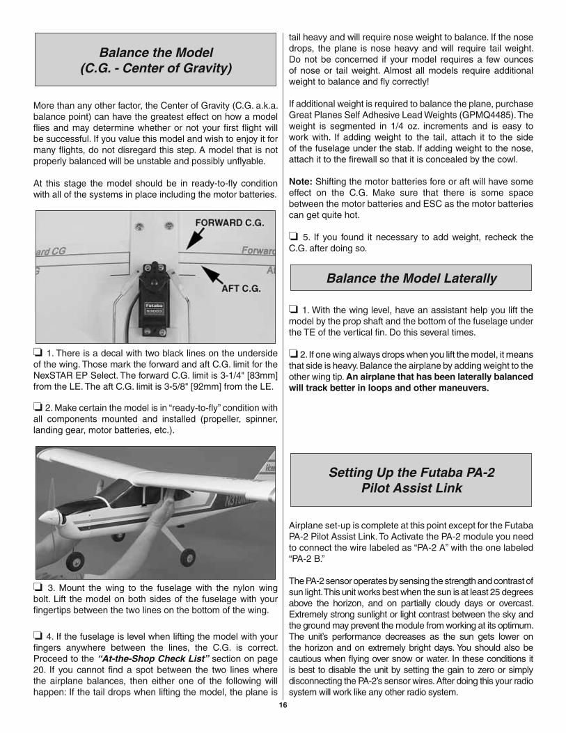
❏ 1. There is a decal with two black lines on the underside of the wing. Those mark the forward and aft C.G. limit for the NexSTAR EP Select. The forward C.G. limit is 3-1/4" [83mm] from the LE. The aft C.G. limit is 3-5/8" [92mm] from the LE.
❏ 2. Make certain the model is in “ready-to-fl y” condition with all components mounted and installed (propeller, spinner, landing gear, motor batteries, etc.).
❏ 3. Mount the wing to the fuselage with the nylon wing bolt. Lift the model on both sides of the fuselage with your fi ngertips between the two lines on the bottom of the wing.
❏ 4. If the fuselage is level when lifting the model with your fi ngers anywhere between the lines, the C.G. is correct. Proceed to the “At-the-Shop Check List” section on page 20. If you cannot fi nd a spot between the two lines where the airplane balances, then either one of the following will happen: If the tail drops when lifting the model, the plane is
tail heavy and will require nose weight to balance. If the nose drops, the plane is nose heavy and will require tail weight. Do not be concerned if your model requires a few ounces of nose or tail weight. Almost all models require additional weight to balance and fl y correctly!
If additional weight is required to balance the plane, purchase Great Planes Self Adhesive Lead Weights (GPMQ4485). The weight is segmented in 1/4 oz. increments and is easy to work with. If adding weight to the tail, attach it to the side of the fuselage under the stab. If adding weight to the nose, attach it to the fi rewall so that it is concealed by the cowl.
Note: Shifting the motor batteries fore or aft will have some effect on the C.G. Make sure that there is some space between the motor batteries and ESC as the motor batteries can get quite hot.
❏ 5. If you found it necessary to add weight, recheck the C.G. after doing so.
Balance the Model Laterally
❏ 1. With the wing level, have an assistant help you lift the model by the prop shaft and the bottom of the fuselage under the TE of the vertical fi n. Do this several times.
❏ 2. If one wing always drops when you lift the model, it means that side is heavy. Balance the airplane by adding weight to the other wing tip. An airplane that has been laterally balanced will track better in loops and other maneuvers.
Setting Up the Futaba PA-2Pilot Assist Link
Airplane set-up is complete at this point except for the Futaba PA-2 Pilot Assist Link. To Activate the PA-2 module you need to connect the wire labeled as “PA-2 A” with the one labeled “PA-2 B.”
The PA-2 sensor operates by sensing the strength and contrast of sun light. This unit works best when the sun is at least 25 degrees above the horizon, and on partially cloudy days or overcast. Extremely strong sunlight or light contrast between the sky and the ground may prevent the module from working at its optimum. The unit’s performance decreases as the sun gets lower on the horizon and on extremely bright days. You should also be cautious when fl ying over snow or water. In these conditions it is best to disable the unit by setting the gain to zero or simply disconnecting the PA-2’s sensor wires. After doing this your radio system will work like any other radio system.
17
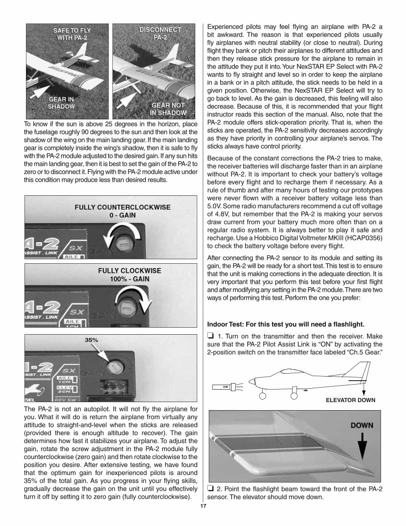
To know if the sun is above 25 degrees in the horizon, place the fuselage roughly 90 degrees to the sun and then look at the shadow of the wing on the main landing gear. If the main landing gear is completely inside the wing’s shadow, then it is safe to fl y with the PA-2 module adjusted to the desired gain. If any sun hits the main landing gear, then it is best to set the gain of the PA-2 to zero or to disconnect it. Flying with the PA-2 module active under this condition may produce less than desired results.
The PA-2 is not an autopilot. It will not fl y the airplane for you. What it will do is return the airplane from virtually any attitude to straight-and-level when the sticks are released (provided there is enough altitude to recover). The gain determines how fast it stabilizes your airplane. To adjust the gain, rotate the screw adjustment in the PA-2 module fully counterclockwise (zero gain) and then rotate clockwise to the position you desire. After extensive testing, we have found that the optimum gain for inexperienced pilots is around 35% of the total gain. As you progress in your fl ying skills, gradually decrease the gain on the unit until you effectively turn it off by setting it to zero gain (fully counterclockwise).
Experienced pilots may feel fl ying an airplane with PA-2 a bit awkward. The reason is that experienced pilots usually fl y airplanes with neutral stability (or close to neutral). During fl ight they bank or pitch their airplanes to different attitudes and then they release stick pressure for the airplane to remain in the attitude they put it into. Your NexSTAR EP Select with PA-2 wants to fl y straight and level so in order to keep the airplane in a bank or in a pitch attitude, the stick needs to be held in a given position. Otherwise, the NexSTAR EP Select will try to go back to level. As the gain is decreased, this feeling will also decrease. Because of this, it is recommended that your fl ight instructor reads this section of the manual. Also, note that the PA-2 module offers stick-operation priority. That is, when the sticks are operated, the PA-2 sensitivity decreases accordingly as they have priority in controlling your airplane’s servos. The sticks always have control priority.
Because of the constant corrections the PA-2 tries to make, the receiver batteries will discharge faster than in an airplane without PA-2. It is important to check your battery’s voltage before every fl ight and to recharge them if necessary. As a rule of thumb and after many hours of testing our prototypes were never fl own with a receiver battery voltage less than 5.0V. Some radio manufacturers recommend a cut off voltage of 4.8V, but remember that the PA-2 is making your servos draw current from your battery much more often than on a regular radio system. It is always better to play it safe and recharge. Use a Hobbico Digital Voltmeter MKIII (HCAP0356) to check the battery voltage before every fl ight.
After connecting the PA-2 sensor to its module and setting its gain, the PA-2 will be ready for a short test. This test is to ensure that the unit is making corrections in the adequate direction. It is very important that you perform this test before your fi rst fl ight and after modifying any setting in the PA-2 module. There are two ways of performing this test. Perform the one you prefer:
Indoor Test: For this test you will need a fl ashlight.
❏ 1. Turn on the transmitter and then the receiver. Make sure that the PA-2 Pilot Assist Link is “ON” by activating the2-position switch on the transmitter face labeled “Ch.5 Gear.”
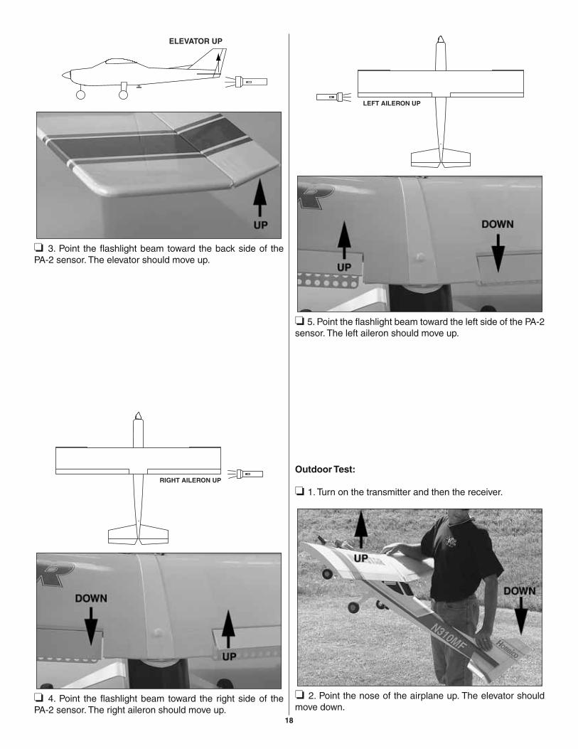
❏ 2. Point the fl ashlight beam toward the front of the PA-2 sensor. The elevator should move down.
18
❏ 3. Point the fl ashlight beam toward the back side of the PA-2 sensor. The elevator should move up.
❏ 4. Point the fl ashlight beam toward the right side of thePA-2 sensor. The right aileron should move up.
❏ 5. Point the fl ashlight beam toward the left side of the PA-2 sensor. The left aileron should move up.
Outdoor Test:
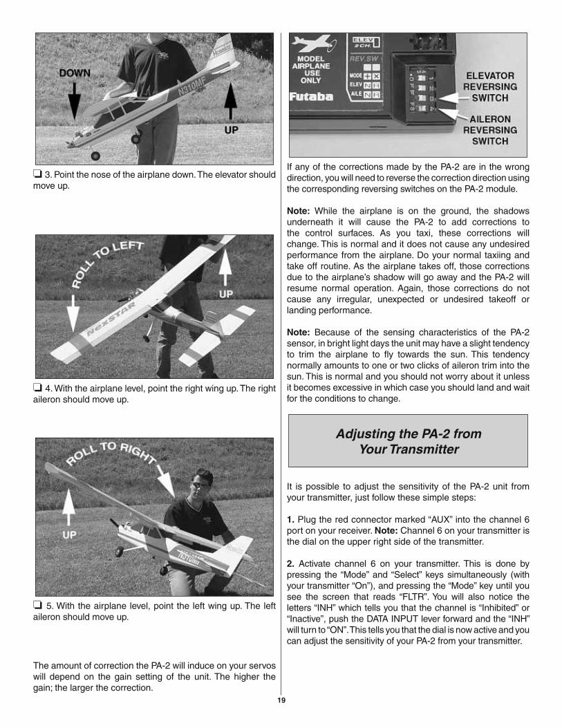
❏ 1. Turn on the transmitter and then the receiver.
❏ 2. Point the nose of the airplane up. The elevator should move down.
19
❏ 3. Point the nose of the airplane down. The elevator should move up.
❏ 4. With the airplane level, point the right wing up. The right aileron should move up.
❏ 5. With the airplane level, point the left wing up. The left aileron should move up.
The amount of correction the PA-2 will induce on your servos will depend on the gain setting of the unit. The higher the gain; the larger the correction.
If any of the corrections made by the PA-2 are in the wrong direction, you will need to reverse the correction direction using the corresponding reversing switches on the PA-2 module.
Note: While the airplane is on the ground, the shadows underneath it will cause the PA-2 to add corrections to the control surfaces. As you taxi, these corrections will change. This is normal and it does not cause any undesired performance from the airplane. Do your normal taxiing and take off routine. As the airplane takes off, those corrections due to the airplane’s shadow will go away and the PA-2 will resume normal operation. Again, those corrections do not cause any irregular, unexpected or undesired takeoff or landing performance.
Note: Because of the sensing characteristics of the PA-2 sensor, in bright light days the unit may have a slight tendency to trim the airplane to fl y towards the sun. This tendency normally amounts to one or two clicks of aileron trim into the sun. This is normal and you should not worry about it unless it becomes excessive in which case you should land and wait for the conditions to change.
Adjusting the PA-2 fromYour Transmitter
It is possible to adjust the sensitivity of the PA-2 unit from your transmitter, just follow these simple steps:
1. Plug the red connector marked “AUX” into the channel 6 port on your receiver. Note: Channel 6 on your transmitter is the dial on the upper right side of the transmitter.
2. Activate channel 6 on your transmitter. This is done by pressing the “Mode” and “Select” keys simultaneously (with your transmitter “On”), and pressing the “Mode” key until you see the screen that reads “FLTR”. You will also notice the letters “INH” which tells you that the channel is “Inhibited” or “Inactive”, push the DATA INPUT lever forward and the “INH” will turn to “ON”. This tells you that the dial is now active and you can adjust the sensitivity of your PA-2 from your transmitter.
20
FINAL PREPARATIONS
Now the plane is assembled, but there are a few things that must be done before it will be ready to fl y. You must carefully perform all of the following procedures.
Gather the Necessary Tools
When you are ready to head out to the fl ying fi eld, there are some items you’ll defi nitely want to have on hand. The most important items include:
• Support equipment – extra battery packs, chargers (for radio and motor batteries), propellers.
• Tools – You won’t need every tool you own, basically just any tools that you used to assemble the plane.
1-#2 Phillips Screwdriver (HCAR1024)1-Long Nose Pliers (HCAR0625)
1-Hobby Knife (HCAR0109)1-3mm Hex Wrench (for prop)
Your fl ight instructor will probably let you share his equipment for a while, but eventually you’ll need your own. Visit your local hobby dealer or see the Hobbico web site for a full selection, descriptions and pricing.
Other Useful Items
• 1 oz. [28g] Thin Pro™ CA adhesive (GPMR6002)• 2 oz. [57g] Spray CA Activator (GPMR6035)• CA Applicator tips (HCAR3780)• CA De-bonder (GPMR6039)• Hook & loop material (GPMQ4480)• Tie straps• Threadlocking compound
…And If You Really Want to Go Nuts• Cooler fi lled with ice and soda• Folding table • Lawn chairs• EZ-up or canopy for shelter• First-aid kit• Paper towels• Spray-on glass cleaner• Sunglasses• Sun block
At-the-Shop Check List
Now it’s time to do a fi nal check before taking the model to the fi eld. These checks are best done in the peace and comfort of your own shop, so take the time now to make certain your model is ready.
❏ 1. Check to see that the screws on the wheel collars that hold on the wheels are fully tightened.
❏ 2. Be certain the silicone retainers on all the nylon clevises are in position.
❏ 3. Make certain the elevator, rudder and ailerons respond in the correct directions.
❏ 4. Make certain the wing is securely joined.❏ 5. Check to see that the fi n bolts that hold the fi n and stab
in position are present and secure.❏ 6. Make certain the propeller, prop adapter and spinner
are secure.❏ 7. Make certain you have balanced the model according
to the instructions.❏ 8. Check to see that the screws that hold the servo arms
to the servos are present and secure.❏ 9. Make certain you have fi lled out the I.D. card on page
27 and place it inside the model.
FLIGHT PREPARATIONS
Flight preparation is to be done at the fl ying fi eld.
Check the Frequency
IMPORTANT: Your radio control system transmits a signal on a certain frequency. Be certain you know what the frequency is. This is expressed as a two-digit number (42, 56, etc.), and can be found on the container the transmitter came in and is also located on the transmitter. There are several different frequencies, but there is still a chance that someone else at the fl ying fi eld may be on the same frequency as you. If you turn on your transmitter while that person is fl ying, a crash will result. NEVER turn on your transmitter until you have permission from your instructor, and until you have possession of the frequency clip used for frequency control at the fl ying site.
Be certain your fl ight instructor performs these following checks with you.
21
Check the Controls
1. Get the frequency clip from the frequency control board at your fl ying site.
2. Mount the wing to the fuselage with the nylon wing bolt supplied with this kit.
3. Turn on the transmitter and receiver. One at a time, operate each control on the airplane using the sticks on the transmitter. Make certain each control is responding correctly. This must be done before every fl ight. There are several types of malfunctions that can be discovered by performing this elementary task, thus saving your model!
Range Check the Radio
A range check must be performed before the fi rst fl ight of a new model. It is not necessary to do a range check before every fl ight (but is not a bad idea to perform a range check before the fi rst fl ight of each day). A range check is the fi nal opportunity to reveal any radio malfunctions, and to be certain the system has adequate operational range.
1. Turn on the transmitter and receiver. Leave the transmitter antenna all the way down. Walk away from the model while simultaneously operating the transmitter controls. Have an assistant stand by the model and tell you what the controls are doing to confi rm that they operate correctly. You should be able to walk approximately 100 feet from the model and still have control without any “glitching” or inadvertent servo operation.2. If everything operates correctly, repeat this test with the motor running at various speeds. If the control surfaces are not always responding correctly, do not fl y! Find and correct the problem fi rst.
Interference can be caused by many factors; here are some things to look for:
• Loose servo connections• Corrosion on connectors• Loose hardware that may cause vibration• Defective radio equipment• Low battery voltage• Damaged receiver antenna or receiver crystal
If the radio appears to only be affected when the motor is running, try moving your receiver farther away from the motor battery and motor.
FLYING
Do not attempt to fl y by yourself. The Hobbico NexSTAR EP Select has many features that make fl ying R/C an easier experience, but the help from an instructor is invaluable. An instructor is going to be able to inspect your airplane to make sure everything is working correctly and he will also be able to give you a few tips and comments on how to improve your fl ying. Also, make sure you fl y at an AMA sanctioned fl ying fi eld.
IMPORTANT: Be aware of your proximity to R/C club sites. If there is an R/C site within six miles of where you are fl ying, and if you are operating your model on the same frequency at the same time as somebody else, there is a strong possibility that one or both models will crash due to radio interference. There is great potential for an out-of-control model to cause property damage and/or severe personal injury. We strongly urge you to fl y at a R/C club site where frequency control is in effect so you can be assured you will be the only one fl ying on your channel.
Taxiing
Remember, it is assumed that your instructor is operating the model for you.
Before the model is ready for takeoff, it must fi rst be set up to roll straight down the runway. Place the plane on the runway and if your fl ying fi eld permits, stand behind the model. Advance the throttle just enough to allow the model to roll. If the model does not roll straight down the runway, shut the power off and adjust the nose gear pushrod as necessary. Do not use the rudder trim to correct the nose wheel because this will also affect the rudder. Note: Crosswinds may affect the direction the model rolls, so this test should be done in calm conditions, or with the model facing directly into the wind.
Takeoff
If possible, takeoff directly into the wind. If you are experienced, taking off in a crosswind is permissible (and sometimes necessary-depending upon the prevailing wind conditions and runway heading). Taking off into the wind will help the model roll straight and also reduces ground speed for takeoff. Taxi the model onto the runway or have an assistant carry it out and set it down, pointing down the runway into the wind. When ready, gradually advance the throttle while simultaneously using the left stick (rudder/nose wheel) to steer the model. Gain as much speed as the runway and fl ying site will practically allow before gently applying up elevator lifting the model into the air. Be ready to make immediate corrections with the ailerons to keep the wings level, and be smooth on the elevator stick, allowing the model to establish a gentle climb to a safe altitude before making the fi rst turn (away from yourself). Do not “yank” back the elevator stick forcing the plane into too steep
22
of a climb which could cause the model to stall. The NexSTAR EP Select includes a powerful brushless motor that will safely pull your airplane up at a 45° angle. If you have the PA-2 Pilot Assist Link on, it will try to level your airplane as soon as you let go of the elevator stick, so make sure you keep some pressure on the stick to keep the airplane climbing.
Flight
Once airborne, maintain a steady climb and make the initial turn away from the runway. When at a comfortable, safe altitude, throttle back to slow the model. This will give you more time to think and react. The NexSTAR EP Select should fl y well at half or slightly less than half-throttle. Adjust the trims so that the plane fl ies straight and level. After fl ying around for awhile still at a safe altitude with plenty of battery power, practice slow fl ight and execute practice landing approaches by reducing the throttle further to see how the model handles when coming in to land. Add power to see how the model climbs as well. Continue to fl y around while learning how the model responds. Mind your battery power level, but use the fi rst fl ight to become familiar with the model before landing.
Landing
When ready to land, pull the throttle stick fully back while fl ying downwind just before making the 180° turn toward the runway. Allow the nose of the model to pitch downward to gradually bleed off altitude. Continue to lose altitude, but maintain airspeed by keeping the nose down while turning. Apply up elevator to level the plane when it reaches the end of the runway and is about fi ve to ten feet off the ground. If the model is too far away, carefully add a small amount of power to fl y the model closer. If going to fast, smoothly advance the throttle and allow the model to gain airspeed. Then apply elevator to climb out and go around to make another attempt. When fi nally ready to touch down, continue to apply up elevator, but not so much that the airplane will climb. Continue to apply up elevator while the plane descends until it gently touches down.
The NexSTAR EP Select has been designed to make steep landing approaches so that the landing approach is short and easy. The SpeedBrakes Training Flaps excel at maintaining fl ying speed even in steep dives, and when the airplane is leveled-out, they also help to increase lift. You can also make a long landing approach and use throttle to keep the airplane fl ying at a very low speed until you reach the runway threshold where you should cut the throttle for the airplane to land.
After you have landed and shut off the power to your model, adjust the pushrods on the ailerons, elevator and rudder as necessary so the trim levers on the transmitter may be returned to center. This will not be required on any of the controls that did not need trim adjustments.
After your fl ight, the motor batteries will be hot. Allow them to cool down before attempting to re-charge them.
MAINTENANCE TIPS
Covering
1. The NexSTAR EP Select is factory-covered with iron-on model covering fi lm. Should repairs ever be required, the covering can be patched with new pieces of iron-on covering. Among several types of covering that will work, Top Flite® MonoKote® fi lm may be used to make repair patches to this model. MonoKote is packaged in six-foot rolls, but some hobby shops also sell it by the foot. If only a small piece of covering is needed for a minor patch, perhaps a fellow modeler would give you some. The covering is applied with a model airplane covering iron, but in an emergency a regular iron set to a lower temperature could be used.
2. Check all screws that hold the wings together, tail bolts, wheel collars, etc.
3. Check all the high-stress areas for cracks or fatigue such as the landing gear area, the wing mounting area, stab and fi n mounting area.
Propeller
Your NexSTAR EP Select comes equipped with a nylon10" x 5" propeller (APCQ4120). After initial fl ights, a 10" x 7" propeller (APCQ4123) will provide a little more power.
Keep clear of the propeller while the motor is armed. This motor is powerful enough to cause damage if anything (including you) gets in the propeller arc.
If the propeller ever gets in contact with anything while the motor is running, inspect it before running it again. Check for cracks, scuffed tips or unbalanced blades. If necessary, replace the propeller.
23
AFTER YOU MASTER THE NEXSTAR EP SELECT IN ITS ORIGINAL FORM
SpeedBrakes Training Flaps
After you feel comfortable fl ying the NexSTAR EP Select and you want to improve its high speed performance, the fi rst thing you can do is to remove the SpeedBrakes Training Flaps by removing the six screws that hold them in place. The NexSTAR EP Select was optimized to fl y with the SpeedBrakes instead of fl aps, so if you remove them, you will have to re-trim the elevator (see page 13). Without fl aps, the NexSTAR EP Select will try to pitch down (nose down) until you re-trim it. Without the SpeedBrakes Training Flaps, the airplane will fl y much faster at any throttle setting and longer landing approaches will be needed. Also, the NexSTAR EP Select will not brake as well on down lines and stall speed will increase slightly.
SpinControl Airfoil Extensions
The second thing you can do to improve the high speed and aerobatic performance of the NexSTAR EP Select is to remove the SpinControl Airfoil Extensions. These extensions at the LE of the wings are held in place with tape that can be carefully removed. Once you remove these extensions, you will need to re-trim your elevator to align it with the stab. The SpinControl Airfoil Extensions produce the opposite effect than the SpeedBrakes Training Flaps in pitch, so if you remove both, the net pitch effect would be almost non existent (see page 13). After you remove these extensions, the NexSTAR EP Select will be faster and able to spin and snap. Also, the stall speed will increase slightly.
Dual Aileron Servos
The Hobbico NexSTAR EP Select comes equipped with dual aileron servo trays for dual aileron servos. If you wish to use fl aperons you will need to upgrade your radio system to 6 channels. To install the dual aileron servos, follow these instructions:
For this section you will need:
1- Additional Aileron Servo (same type as thatalready installed in your NexSTAR EP Select
1-“Y” harness 2-6" [152mm] Pushrods2-Nylon Clevises2-Silicone Clevis Retainers
2-Faslinks1-Servo Mounting Hardware Set1-Screwdriver1-Wire Cutter1-Pliers1-Thin CA1-Trim Sealing Iron
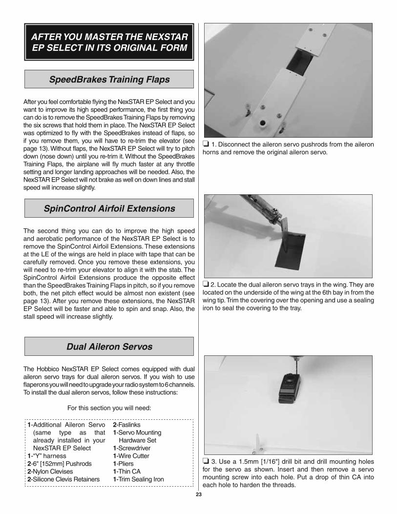
❏ 1. Disconnect the aileron servo pushrods from the aileron horns and remove the original aileron servo.
❏ 2. Locate the dual aileron servo trays in the wing. They are located on the underside of the wing at the 6th bay in from the wing tip. Trim the covering over the opening and use a sealing iron to seal the covering to the tray.
❏ 3. Use a 1.5mm [1/16"] drill bit and drill mounting holes for the servo as shown. Insert and then remove a servo mounting screw into each hole. Put a drop of thin CA into each hole to harden the threads.
24
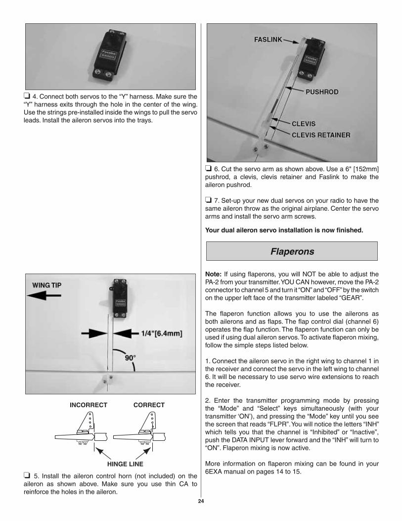
❏ 4. Connect both servos to the “Y” harness. Make sure the “Y” harness exits through the hole in the center of the wing. Use the strings pre-installed inside the wings to pull the servo leads. Install the aileron servos into the trays.
❏ 5. Install the aileron control horn (not included) on the aileron as shown above. Make sure you use thin CA to reinforce the holes in the aileron.
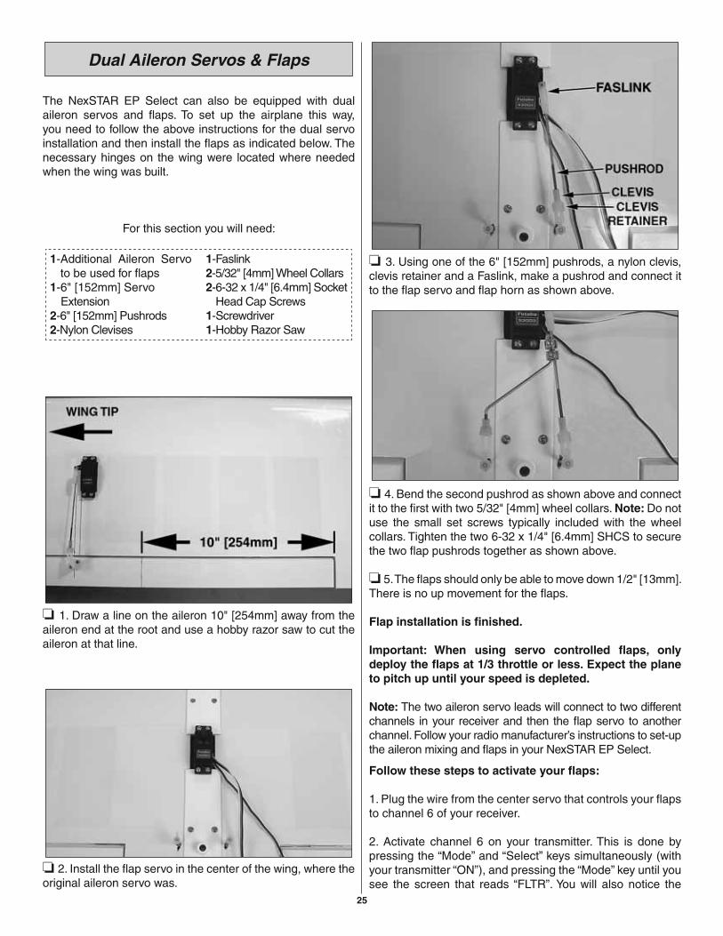
❏ 6. Cut the servo arm as shown above. Use a 6" [152mm] pushrod, a clevis, clevis retainer and Faslink to make the aileron pushrod.
❏ 7. Set-up your new dual servos on your radio to have the same aileron throw as the original airplane. Center the servo arms and install the servo arm screws.
Your dual aileron servo installation is now fi nished.
Flaperons
Note: If using fl aperons, you will NOT be able to adjust the PA-2 from your transmitter. YOU CAN however, move the PA-2 connector to channel 5 and turn it “ON” and “OFF” by the switch on the upper left face of the transmitter labeled “GEAR”.
The fl aperon function allows you to use the ailerons as both ailerons and as fl aps. The fl ap control dial (channel 6) operates the fl ap function. The fl aperon function can only be used if using dual aileron servos. To activate fl aperon mixing, follow the simple steps listed below.
1. Connect the aileron servo in the right wing to channel 1 in the receiver and connect the servo in the left wing to channel 6. It will be necessary to use servo wire extensions to reach the receiver.
2. Enter the transmitter programming mode by pressing the “Mode” and “Select” keys simultaneously (with your transmitter ‘ON’), and pressing the “Mode” key until you see the screen that reads “FLPR”. You will notice the letters “INH” which tells you that the channel is “Inhibited” or “Inactive”, push the DATA INPUT lever forward and the “INH” will turn to “ON”. Flaperon mixing is now active.
More information on fl aperon mixing can be found in your 6EXA manual on pages 14 to 15.
25
Dual Aileron Servos & Flaps
The NexSTAR EP Select can also be equipped with dual aileron servos and fl aps. To set up the airplane this way, you need to follow the above instructions for the dual servo installation and then install the fl aps as indicated below. The necessary hinges on the wing were located where needed when the wing was built.
For this section you will need:
1- Additional Aileron Servo to be used for fl aps
1-6" [152mm] Servo Extension2-6" [152mm] Pushrods2-Nylon Clevises
1-Faslink2-5/32" [4mm] Wheel Collars2- 6-32 x 1/4" [6.4mm] Socket
Head Cap Screws1-Screwdriver1-Hobby Razor Saw
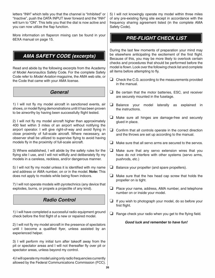
❏ 1. Draw a line on the aileron 10" [254mm] away from the aileron end at the root and use a hobby razor saw to cut the aileron at that line.
❏ 2. Install the fl ap servo in the center of the wing, where the original aileron servo was.
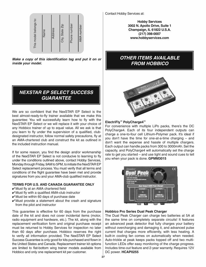
❏ 3. Using one of the 6" [152mm] pushrods, a nylon clevis, clevis retainer and a Faslink, make a pushrod and connect it to the fl ap servo and fl ap horn as shown above.
❏ 4. Bend the second pushrod as shown above and connect it to the fi rst with two 5/32" [4mm] wheel collars. Note: Do not use the small set screws typically included with the wheel collars. Tighten the two 6-32 x 1/4" [6.4mm] SHCS to secure the two fl ap pushrods together as shown above.
❏ 5. The fl aps should only be able to move down 1/2" [13mm]. There is no up movement for the fl aps.
Flap installation is fi nished.
Important: When using servo controlled fl aps, only deploy the fl aps at 1/3 throttle or less. Expect the plane to pitch up until your speed is depleted.
Note: The two aileron servo leads will connect to two different channels in your receiver and then the fl ap servo to another channel. Follow your radio manufacturer’s instructions to set-up the aileron mixing and fl aps in your NexSTAR EP Select.
Follow these steps to activate your fl aps:
1. Plug the wire from the center servo that controls your fl aps to channel 6 of your receiver.
2. Activate channel 6 on your transmitter. This is done by pressing the “Mode” and “Select” keys simultaneously (with your transmitter “ON”), and pressing the “Mode” key until you see the screen that reads “FLTR”. You will also notice the
26
letters “INH” which tells you that the channel is “Inhibited” or “Inactive”, push the DATA INPUT lever forward and the “INH” will turn to “ON”. This tells you that the dial is now active and you can now utilize the fl ap function.
More information on fl aperon mixing can be found in your 6EXA manual on page 15.
AMA SAFETY CODE (excerpts)
Read and abide by the following excerpts from the Academy of Model Aeronautics Safety Code. For the complete Safety Code refer to Model Aviation magazine, the AMA web site, or the Code that came with your AMA license.
General
1) I will not fl y my model aircraft in sanctioned events, air shows, or model fl ying demonstrations until it has been proven to be airworthy by having been successfully fl ight tested.
2) I will not fl y my model aircraft higher than approximately 400 feet within 3 miles of an airport without notifying the airport operator. I will give right-of-way and avoid fl ying in close proximity of full-scale aircraft. Where necessary, an observer shall be utilized to supervise fl ying to avoid having models fl y in the proximity of full-scale aircraft.
3) Where established, I will abide by the safety rules for the fl ying site I use, and I will not willfully and deliberately fl y my models in a careless, reckless, and/or dangerous manner.
5) I will not fl y my model unless it is identifi ed with my name and address or AMA number, on or in the model. Note: This does not apply to models while being fl own indoors.
7) I will not operate models with pyrotechnics (any device that explodes, burns, or propels a projectile of any kind).
Radio Control
1) I will have completed a successful radio equipment ground check before the fi rst fl ight of a new or repaired model.
2) I will not fl y my model aircraft in the presence of spectators until I become a qualifi ed fl yer, unless assisted by an experienced helper.
3) I will perform my initial turn after takeoff away from the pit or spectator areas and I will not thereafter fl y over pit or spectator areas, unless beyond my control.
4) I will operate my model using only radio frequencies currently allowed by the Federal Communications Commission (FCC).
5) I will not knowingly operate my model within three miles of any pre-existing fl ying site except in accordance with the frequency sharing agreement listed (in the complete AMA Safety Code).
PRE-FLIGHT CHECK LIST
During the last few moments of preparation your mind may be elsewhere anticipating the excitement of the fi rst fl ight. Because of this, you may be more likely to overlook certain checks and procedures that should be performed before the model is fl own. Look over the following check list and complete all items before attempting to fl y.
❏ Check the C.G. according to the measurements provided in the manual.
❏ Be certain that the motor batteries, ESC, and receiver are securely mounted in the fuselage.
❏ Balance your model laterally as explained inthe instructions.
❏ Make sure all hinges are damage-free and securely glued in place.
❏ Confi rm that all controls operate in the correct direction and the throws are set up according to the manual.
❏ Make sure that all servo arms are secured to the servos.
❏ Make sure that any servo extension wires that you have do not interfere with other systems (servo arms, pushrods, etc.)
❏ Balance your propeller (and spare propellers).
❏ Make sure that the hex head cap screw that holds the propeller on is tight.
❏ Place your name, address, AMA number, and telephone number on or inside your model.
❏ If you wish to photograph your model, do so before your fi rst fl ight.
❏ Range check your radio when you get to the fl ying fi eld.
Good luck and remember to have fun!
27
Make a copy of this identifi cation tag and put it on or inside your model.
NEXSTAR EP SELECT SUCCESS GUARANTEE
We are so confi dent that the NexSTAR EP Select is the best almost-ready-to-fl y trainer available that we make this guarantee: You will successfully learn how to fl y with the NexSTAR EP Select or we will replace it with your choice of any Hobbico trainer of up to equal value. All we ask is that you learn to fl y under the supervision of a qualifi ed, club-designated instructor, follow normal safety precautions, fl y at an AMA-chartered club and construct the kit as outlined in the included instruction manual.
If for some reason, you fi nd the design and/or workmanship of the NexSTAR EP Select is not conducive to learning to fl y under the conditions outlined above, contact Hobby Services, Monday through Friday, 9AM to 5PM, to initiate the NexSTAR EP Select replacement process. You must verify that all terms and conditions of the fl ight guarantee have been met and provide signatures from you and your AMA-club qualifi ed instructor.
TERMS FOR U.S. AND CANADA GUARANTEE ONLY✔ Must fl y at an AMA chartered fi eld✔ Must fl y with a qualifi ed AMA-club instructor✔ Must be within 60 days of purchase date✔ Must provide a statement about the crash and signature
from the pilot and instructor
This guarantee is effective for 60 days from the purchase date of the kit and does not cover incidental items (motor, radio equipment and hardware, etc.). The kit, along with the replacement verifi cation form and original purchase receipt must be returned to Hobby Services for inspection no later than 60 days after purchase. Hobbico reserves the right to verify all information provided. The NexSTAR EP Select Success Guarantee is only good for kits purchased and fl own in the United States and Canada. Replacement trainer kit options are limited to fl at-bottom wing trainer models available from Hobbico and only one replacement kit per customer.
Contact Hobby Services at:
Hobby Services3002 N. Apollo Drive, Suite 1Champaign, IL 61822 U.S.A.
(217) 398-0007www.hobbyservices.com
OTHER ITEMS AVAILABLEFROM HOBBICO
ElectriFly™ PolyCharge4™
For convenience with multiple LiPo packs, there’s the DC PolyCharge4. Each of its four independent outputs can charge a one-to-four cell Lithium-Polymer pack. It’s ideal if you don’t have the time for one-at-a-time charging – and don’t want the expense and hassle of multiple chargers. Each output can handle packs from 300 to 3000mAh. Set the capacity, and PolyCharge4 will automatically set the charge rate to get you started – and use light and sound cues to tell you when your pack is done. GPMM3015
Hobbico Pro Series Dual Peak ChargerThe Dual Peak Charger can charge two batteries at 5A at the same time on completely separate circuits! It features an advanced peak detector that fully charges your battery without overcharging and damaging it, and advanced pulse current that charges more efficiently, with less heating. A built-in cooling fan comes on automatically when needed. Auto-trickle at peak keeps packs topped off and two multi-function LEDs offer easy monitoring of the charge progress. Includes time-out feature and 2-year warranty. Requires 12V DC power. HCAP0255

BUILDING NOTES
Kit Purchased Date: ___________________________
Where Purchased: ____________________________
Date Construction Started: _____________________
Date Construction Finished: _______________________
Finished Weight: _______________________________
Date of First Flight: ______________________________
FLIGHT LOG


![DLE-35RA - Hobbico - Hobbico, Inc. - largest U.S ...manuals.hobbico.com/dle/dleg0435-manual.pdfDLE with Manual Choke Main Engine − 2.08lb [947g] ... DLE-35RA Gas Engine with DLE](https://img.pdfslide.us/doc/110x75/5abf1f1d7f8b9a3a428dcf03/dle-35ra-hobbico-hobbico-inc-largest-us-with-manual-choke-main-engine.jpg)