Embed Size (px)
Citation preview
Instruction manual
Scrubmaster B12 (7745.02)

EN
EN-1
Dear Customer,Thank you for choosing one of our cleaning products.
The floor scrubber dryer that you have purchased has been designed to satisfy the user in terms of ease of use and reliability over time.
We are aware that in order for a good product to stay that way, over time, it requires continuous updates aimed at meeting the expectations of those who use it on a daily basis. For this reason, we hope that you will not only be a satisfied customer but also a partner who does not hesitate to give us your opinions and ideas originating from your personal day-to-day experience.
Before the first use of your floor scrubber read this original instruction manual, then operate and keep this instruction manual for later use or for next owners.
EN
EN-2
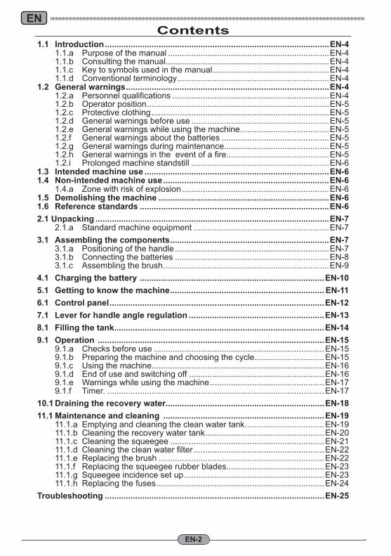
1.1 Introduction ................................................................................................EN-4 1.1.a Purpose of the manual .....................................................................EN-4 1.1.b Consulting the manual......................................................................EN-4 1.1.c Key to symbols used in the manual..................................................EN-4 1.1.d Conventional terminology .................................................................EN-41.2 General warnings .......................................................................................EN-4 1.2.a Personnelqualifications ...................................................................EN-4 1.2.b Operator position ..............................................................................EN-5 1.2.c Protective clothing ............................................................................EN-5 1.2.d General warnings before use ...........................................................EN-5 1.2.e General warnings while using the machine ......................................EN-5 1.2.f General warnings about the batteries ..............................................EN-5 1.2.g General warnings during maintenance.............................................EN-5 1.2.h Generalwarningsintheeventofafire............................................EN-5 1.2.i Prolonged machine standstill ...........................................................EN-61.3 Intended machine use ...............................................................................EN-61.4 Non-intended machine use .......................................................................EN-6 1.4.a Zone with risk of explosion ...............................................................EN-61.5 Demolishing the machine .........................................................................EN-61.6 Reference standards .................................................................................EN-62.1 Unpacking ....................................................................................................EN-7 2.1.a Standard machine equipment ..........................................................EN-73.1 Assembling the components ....................................................................EN-7 3.1.a Positioning of the handle ..................................................................EN-7 3.1.b Connecting the batteries ..................................................................EN-8 3.1.c Assembling the brush .......................................................................EN-94.1 Charging the battery ...............................................................................EN-105.1 Getting to know the machine .................................................................. EN-116.1 Control panel ............................................................................................EN-127.1 Lever for handle angle regulation ..........................................................EN-138.1 Filling the tank ..........................................................................................EN-149.1 Operation .................................................................................................EN-15 9.1.a Checks before use .........................................................................EN-15 9.1.b Preparing the machine and choosing the cycle..............................EN-15 9.1.c Using the machine..........................................................................EN-16 9.1.d End of use and switching off ..........................................................EN-16 9.1.e Warnings while using the machine .................................................EN-17 9.1.f Timer. .............................................................................................EN-1710.1 Draining the recovery water....................................................................EN-1811.1 Maintenance and cleaning .....................................................................EN-19 11.1.a Emptying and cleaning the clean water tank ..................................EN-19 11.1.b Cleaning the recovery water tank ...................................................EN-20 11.1.c Cleaning the squeegee ..................................................................EN-21 11.1.d Cleaningthecleanwaterfilter ........................................................EN-22 11.1.e Replacing the brush .......................................................................EN-22 11.1.f Replacing the squeegee rubber blades..........................................EN-23 11.1.g Squeegee incidence set up ............................................................EN-23 11.1.h Replacing the fuses ........................................................................EN-24Troubleshooting ..............................................................................................EN-25
Contents
EN
EN-3
Technical data
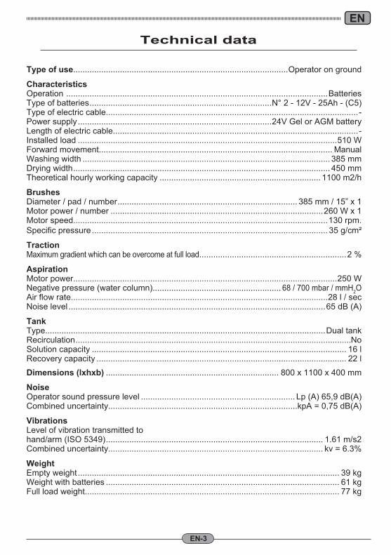
Type of use............................................................................................Operator on ground
CharacteristicsOperation ................................................................................................................BatteriesType of batteries ..............................................................................N° 2 - 12V - 25Ah - (C5)Type of electric cable............................................................................................................-Power supply ...................................................................................24V Gel or AGM batteryLength of electric cable.........................................................................................................-Installed load ...............................................................................................................510 WForward movement.................................................................................................... ManualWashing width .......................................................................................................... 385 mmDrying width .............................................................................................................. 450 mmTheoretical hourly working capacity ..................................................................... 1100 m2/h
BrushesDiameter / pad / number ............................................................................. 385 mm / 15” x 1Motor power / number ...........................................................................................260 W x 1Motor speed.............................................................................................................130 rpm.Specific pressure ..................................................................................................... 35 g/cm²
TractionMaximum gradient which can be overcome at full load ...............................................................2 %
AspirationMotor power.................................................................................................................250 WNegative pressure (water column)....................................................... 68 / 700 mbar / mmH2OAir flow rate..............................................................................................................28 l / secNoise level ..............................................................................................................65 dB (A)
TankType........................................................................................................................Dual tankRecirculation ......................................................................................................................NoSolution capacity ............................................................................................................. 16 lRecovery capacity ........................................................................................................... 22 l
Dimensions (lxhxb) .......................................................................... 800 x 1100 x 400 mm
NoiseOperator sound pressure level .................................................................. Lp (A) 65,9 dB(A)Combined uncertainty.................................................................................kpA = 0,75 dB(A)
VibrationsLevel of vibration transmitted tohand/arm (ISO 5349) ............................................................................................. 1.61 m/s2Combined uncertainty............................................................................................ kv = 6.3%
WeightEmpty weight ................................................................................................................ 39 kgWeight with batteries .................................................................................................... 61 kgFull load weight............................................................................................................. 77 kg
EN
EN-4
1.1 INTRODUCTIONThe manual is an integral part of the machine itself; it must therefore be stored carefully in a safe place which is accessible to all users (oper-ators and personnel in charge of maintenance) for the entire machine life until demolition.
1.1.a - Purpose of the manualThe purpose of the manual is to provide the instructions necessary for putting into serv-ice, using and maintaining the machine with which it is enclosed.
It is advisable to read the instructions care-fully and comply with the safety standards described in the manual to the letter.
The non-observance of these instructions/stand-ards may cause damage to the machine and in-jury to the operator for which under no circum-stances is the manufacturer responsible.
The safety information described in the man-ual supplements and DOES NOT REPLACE standards in force in the country in which the machine is used.
1.1.b - Consulting the manualThe manual is divided into chapters accord-ing to a logical order of knowledge and use of the machine.For help with finding a specific topic, first consult the CONTENTS shown at the begin-ning of the manual.
1.1.c - Key to symbols used in the manual
In order to highlight information and proce-dures regarding safety, maintenance etc., the following symbols have been adopted in the manual:
DANGER:Warns of a serious, even fatal danger for the safety of the operator and/or third per-sons.
WARNING:Extremely important information in or-der to prevent serious damage to the machine and the environment in which it operates.
N.B.:Additional information for correct machine operation or of a general nature.
1.1.d - Conventional terminologyThe terms front, rear, forward, back, upper, lower, left and right refer to the operator in the working position with his/her hands on the guide handle.To simplify, the brand name of the model has been replaced with “Machine”.
The machine comes in two versions:- BC: version with batteries- E: version with electric cable
1.2 GENERAL WARNINGS
Before putting into service, using and main-taining the machine, it is necessary for the persons involved (persons in charge and op-erators) to be trained regarding the operating procedures and safety standards shown in this manual.Respect all the provisions contained in the manual and in any enclosed documentation.
DANGER:It is forbidden for untrained personnel, children and disabled persons to use the machine.
1.2.a - Personnel qualificationsOperatorThe term operator refers to a generic worker able to perform simple operations such as running the machine and carrying out the relative cleaning at the end of the working shift.
Electrical/mechanical maintenance technicianA technician qualified to operate on the ma-chine in order to repair or replace parts which require the removal of the protective cover.
EN
EN-5
1.2.b - Operator positionWhile using the machine, the operator is po-sition at the rear of the machine with his/her hands on the handle.
1.2.c - Protective clothing- Use protective clothing as indicated in the
standards in force in the country in which the machine is used.
1.2.d - General warnings before use- Before using the machine, check that the
fixed safety guards (covers) are always correctly secured in position.
1.2.e - General warnings while using the machine
- If the machine makes strange noises, stop it immediately and identify the cause.
- Do NOT abandon the machine on sur-faces which slope by more than 2%.
- While using the machine, do not knock into shelving or cupboards.
- It is forbidden to use the machine out-doors or on public roads.
- If possible, use the machine in environ-ments where no persons are present; in the present of unauthorised persons, warn them to move away before using the machine.
- Do not use the machine in environments with the presence of corrosive or salty substances.
- Do not use the machine in explosive en-vironments (ATEX).
- It is not advisable to use an adaptor, mul-tiple sockets, or an extension cord.
- If the electrical cord of this appliance is damaged, it must be replaced by an Au-thorized Customer Service Centre.
1.2.f - General warnings about the batteries
- Use appropriate personal protection equipment to avoid contact with the skin (see standards in force in the country in which the machine is used).
- Do not inhale the vapour: it is danger-ous.
- It is forbidden to smoke and/or use na-ked flames within 2 metres of the battery during charging, in the charging area and while the battery is cooling after charg-ing.
- Report any liquid leaking from the battery: leaks are dangerous and highly pollut-
ing.- Use only sealed GEL or AGM batteries.- Batteries must be replaced only by quali-
fied personnel.
1.2.g - General warnings during maintenance
- Disconnect the batteries before perform-ing maintenance and repair operations.
- Do not rest tools and metal objects on the batteries; danger of short circuits.
- Do not use aggressive detergents, acid, lye etc. during cleaning and washing and take particular care with electrical parts.
- Do not wash the machine with direct or pressurised jets of water.
- When the machine must be lifted for any maintenance operations, it is necessary to work safely by placing fixed supports underneath it.
- Contact an authorised support centre for repairs and request ORIGINAL spare parts only.
1.2.h - General warnings in the event of a fire
- In the event of a fire, use approved pow-der extinguishers only; do NOT use water to put out the fire.
EN
EN-6
1.4.a - Zone with risk of explosionIt is strictly forbidden to use the machine in environments where there is a risk of explo-sion with the presence of flammable and explosive gases, vapours, liquids and pow-ders.
1.5. DEMOLISHING THE MACHINE
In order to protect the environment, proceed in compliance with local standards in force. When the appliance can no longer be used or repaired, proceed with the separate dis-posal of its components.
Electrical equipment cannot be disposed of as urban waste and it is necessary to dispose of it separately as in-troduced by the special regulation regarding the disposal of waste originating from electrical equip-ment (Italian Legislative Decree no. 151 of 25/7/05 - 2002/96/EC - 2003/108/EC).
The electrical equipment is marked with a sym-bol showing a wheeled bin with a cross on it. The symbol indicates that the equipment was put on the market after 13 August 2005 and that it must be disposed of separately.
In consideration of the substances and ma-terials contained, inadequate or abusive dis-posal of the equipment or its improper use may cause damage or injury to persons and the environment.
Disposal of electrical waste which does not respect the standards in force leads to the application of administrative sanctions and penalties.
1.6. REFERENCE STANDARDS
This machine has been built in compliance with the machine directive in force and in ac-cordance with the standards contained in the EC Declaration of Conformity supplied with the machine.
1.2.i - Prolonged machine standstill- Place the machine under cover, shel-
tered from atmospheric agents in a place where the temperature is between 5°C and +40°C.
- Remove the ignition key.- Drain the clean water contained in the
tank.- Charge the batteries and, once they
are charged, disconnect them from the charger.
- Charge the batteries once a month.
1.3. INTENDED MACHINE USE
The machine has been designed and manu-factured for cleaning indoor floor surfaces.
DANGER:Any other use releases the manufacturer from responsibility for damage or injury to persons and/or things and invalidates any warranty condition.
1.4 - NON-INTENDED MACHINE USE
WARNING:The machine is not intended for outdoor use.
DANGER:- washing floors with water which is hotter
than 50°C;- using diesel/petrol or corrosive deter-
gents to wash floors;- washing and sucking up corrosive, flam-
mable and/or explosive liquids, even if diluted.
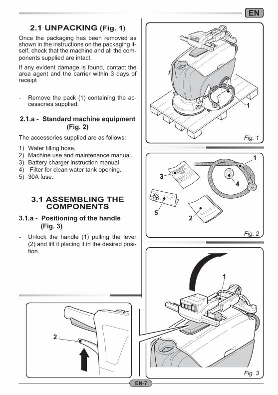
Fig. 1
Fig. 2
1
34
Fig. 3
34
25
1
1
2
EN
EN-7
2.1 UNPACKING (Fig. 1)Once the packaging has been removed as shown in the instructions on the packaging it-self, check that the machine and all the com-ponents supplied are intact.If any evident damage is found, contact the area agent and the carrier within 3 days of receipt
- Remove the pack (1) containing the ac-cessories supplied.
2.1.a - Standard machine equipment(Fig. 2)
The accessories supplied are as follows:
1) Water filling hose.2) Machine use and maintenance manual.3) Battery charger instruction manual4) Filter for clean water tank opening.5) 30A fuse.
3.1 ASSEMBLING THECOMPONENTS
3.1.a - Positioning of the handle (Fig. 3)- Unlock the handle (1) pulling the lever
(2) and lift it placing it in the desired posi-tion.
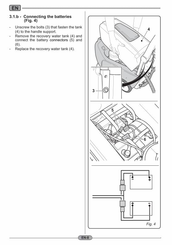
Fig. 4
4
3
5
6
EN
EN-8
3.1.b - Connecting the batteries (Fig. 4)- Unscrew the bolts (3) that fasten the tank
(4) to the handle support.- Remove the recovery water tank (4) and
connect the battery connectors (5) and (6).
- Replace the recovery water tank (4).
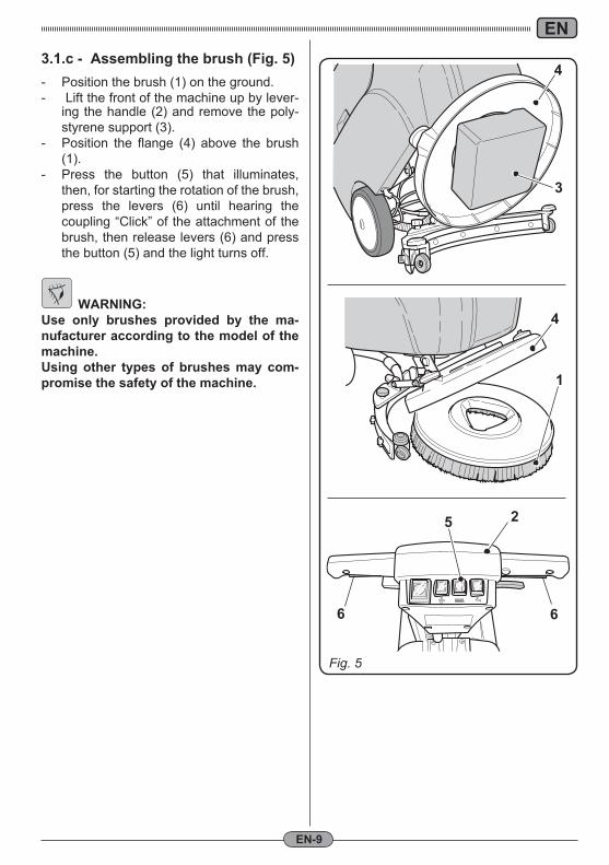
Fig. 5
1
3
4
4
6
2
6
5
EN
EN-9
3.1.c - Assembling the brush (Fig. 5)- Position the brush (1) on the ground.- Lift the front of the machine up by lever-
ing the handle (2) and remove the poly-styrene support (3).
- Position the flange (4) above the brush (1).
- Press the button (5) that illuminates, then, for starting the rotation of the brush, press the levers (6) until hearing the coupling “Click” of the attachment of the brush, then release levers (6) and press the button (5) and the light turns off.
WARNING:Use only brushes provided by the ma-nufacturer according to the model of the machine.Using other types of brushes may com-promise the safety of the machine.
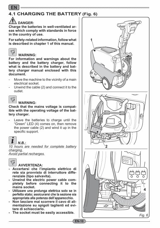
Fig. 6
2
4
1
EN
EN-10
DANGER:Charge the batteries in well-ventilated ar-eas which comply with standards in force in the country of use.For safety-related information, follow what is described in chapter 1 of this manual.
WARNING:For information and warnings about the battery and the battery charger, follow what is described in the battery and bat-tery charger manual enclosed with this document.- Move the machine to the vicinity of a main
electrical socket.- Unwind the cable (2) and connect it to the
outlet.
WARNING:Check that the mains voltage is compat-ible with the operating voltage of the bat-tery charger.- Leave the batteries to charge until the
“Green” LED (4) comes on, then remove the power cable (2) and wind it up in the specific support.
N.B.: 10 hours are needed for complete battery charging. Avoid partial recharges.
AVVERTENZA:- Accertarsi che l’impianto elettrico di
rete sia provvisto di interruttore diffe-renziale (tipo salvavita).
- Unwind the electric power cable com-pletely before connecting it to the mains socket.
- Utilizzare una prolunga elettrica solo se in perfetto stato; assicurarsi che la sezione sia appropriata alla potenza dell’apparecchio.
- Non lasciare mai scorrere il cavo di ali-mentazione su spigoli taglienti ed evi-tare di schiacciarlo.
- The socket must be easily accessible.
4.1 CHARGING THE BATTERY (Fig. 6)
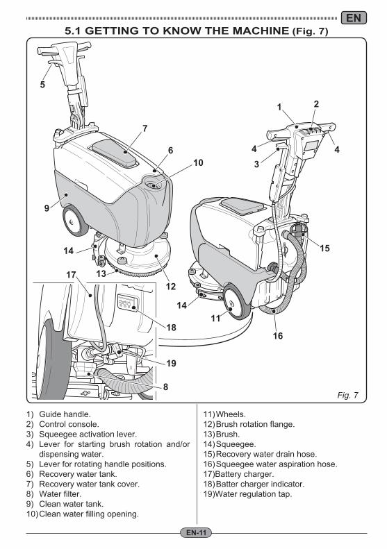
Fig. 7
Fig. 6
4
2
36
7
9
10
11
1213
14 15
16
17
18
19
8
14
4
5
1
EN
EN-11
5.1 GETTING TO KNOW THE MACHINE (Fig. 7)
1) Guide handle.2) Control console.3) Squeegee activation lever.4) Lever for starting brush rotation and/or
dispensing water.5) Lever for rotating handle positions.6) Recovery water tank.7) Recovery water tank cover.8) Water filter.9) Clean water tank.10) Clean water filling opening.
11) Wheels.12) Brush rotation flange.13) Brush.14) Squeegee.15) Recovery water drain hose.16) Squeegee water aspiration hose.17)Battery charger.18) Batter charger indicator.19)Water regulation tap.
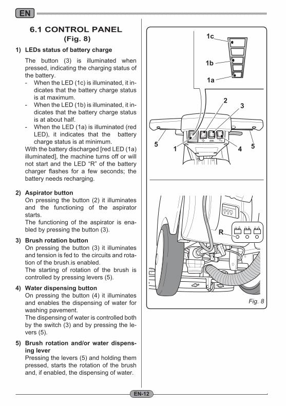
Fig. 8
R
1a
1b
1c
5 5
3
4
2
1
EN
EN-12
6.1 CONTROL PANEL (Fig. 8)
1) LEDs status of battery charge The button (3) is illuminated when
pressed, indicating the charging status of the battery.- When the LED (1c) is illuminated, it in-
dicates that the battery charge status is at maximum.
- When the LED (1b) is illuminated, it in-dicates that the battery charge status is at about half.
- When the LED (1a) is illuminated (red LED), it indicates that the battery charge status is at minimum.
With the battery discharged [red LED (1a) illuminated], the machine turns off or will not start and the LED “R” of the battery charger flashes for a few seconds; the battery needs recharging.
2) Aspirator button On pressing the button (2) it illuminates
and the functioning of the aspirator starts.
The functioning of the aspirator is ena-bled by pressing the button (3).
3) Brush rotation button On pressing the button (3) it illuminates
and tension is fed to the circuits and rota-tion of the brush.is enabled.
The starting of rotation of the brush is controlled by pressing levers (5).
4) Water dispensing button On pressing the button (4) it illuminates
and enables the dispensing of water for washing pavement.
The dispensing of water is controlled both by the switch (3) and by pressing the le-vers (5).
5) Brush rotation and/or water dispens-ing lever
Pressing the levers (5) and holding them pressed, starts the rotation of the brush and, if enabled, the dispensing of water.
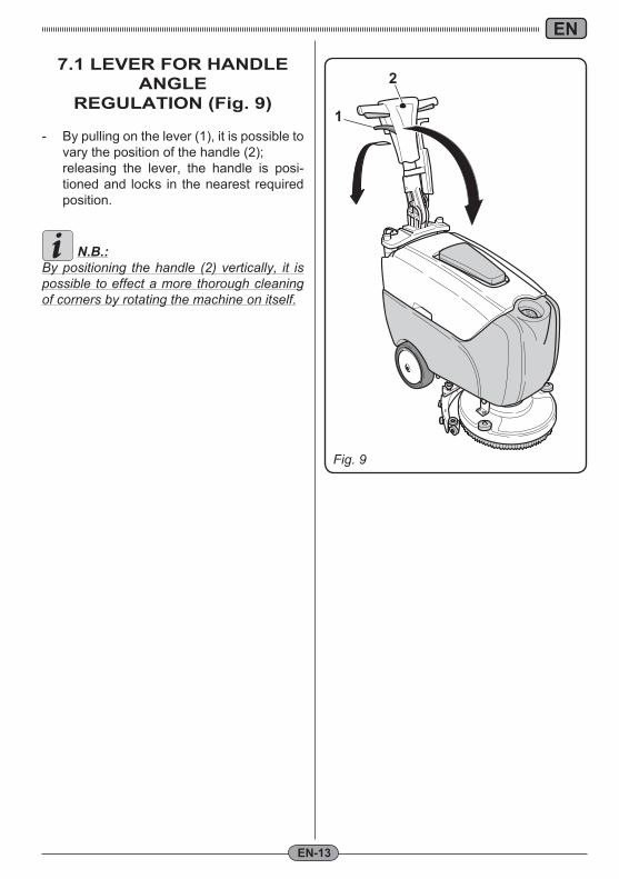
Fig. 8
1
2
Fig. 9
EN
EN-13
7.1 LEVER FOR HANDLE ANGLE
REGULATION (Fig. 9)
- By pulling on the lever (1), it is possible to vary the position of the handle (2);
releasing the lever, the handle is posi-tioned and locks in the nearest required position.
N.B.:By positioning the handle (2) vertically, it is possible to effect a more thorough cleaning of corners by rotating the machine on itself.
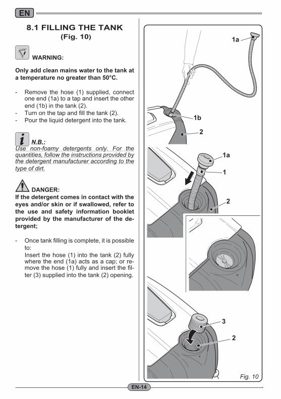
Fig. 10
1
1a
1a
1b
2
2
2
3
EN
EN-14
8.1 FILLING THE TANK (Fig. 10)
WARNING:
Only add clean mains water to the tank at a temperature no greater than 50°C.
- Remove the hose (1) supplied, connect one end (1a) to a tap and insert the other end (1b) in the tank (2).
- Turn on the tap and fill the tank (2).- Pour the liquid detergent into the tank.
N.B.:Use non-foamy detergents only. For the quantities, follow the instructions provided by the detergent manufacturer according to the type of dirt.
DANGER:If the detergent comes in contact with the eyes and/or skin or if swallowed, refer to the use and safety information booklet provided by the manufacturer of the de-tergent;
- Once tank filling is complete, it is possible to:
Insert the hose (1) into the tank (2) fully where the end (1a) acts as a cap; or re-move the hose (1) fully and insert the fil-ter (3) supplied into the tank (2) opening.
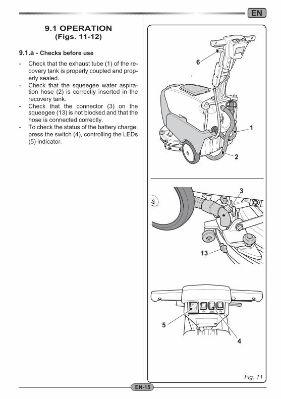
Fig. 11
4
5
1
3
13
2
6
EN
EN-15
9.1 OPERATION (Figs. 11-12)
9.1.a - Checks before use
- Check that the exhaust tube (1) of the re-covery tank is properly coupled and prop-erly sealed.
- Check that the squeegee water aspira-tion hose (2) is correctly inserted in the recovery tank.
- Check that the connector (3) on the squeegee (13) is not blocked and that the hose is connected correctly.
- To check the status of the battery charge; press the switch (4), controlling the LEDs (5) indicator.
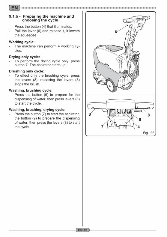
Fig. 11
98
47
8
6
EN
EN-16
9.1.b - Preparing the machine and choosing the cycle- Press the button (4) that illuminates.- Pull the lever (6) and release it, it lowers
the squeegee.
Working cycle:- The machine can perform 4 working cy-
cles:
Drying only cycle:- To perform the drying cycle only, press
button 7. The aspirator starts up.
Brushing only cycle:- To effect only the brushing cycle, press
the levers (8), releasing the levers (8) stops the brush.
Washing, brushing cycle:- Press the button (9) to prepare for the
dispensing of water, then press levers (8) to start the cycle.
Washing, brushing, drying cycle:- Press the button (7) to start the aspirator,
the button (9) to prepare the dispensing of water, then press the levers (8) to start the cycle.
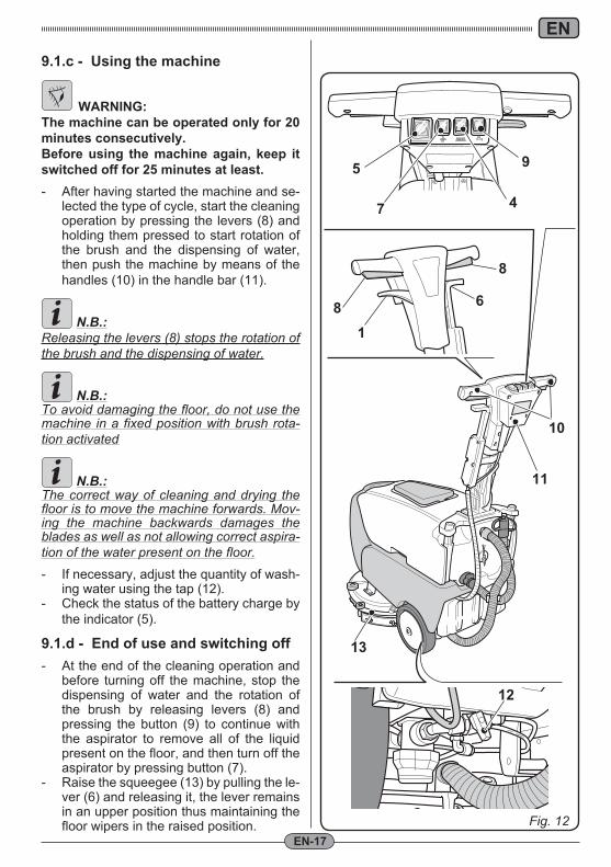
Fig. 12
10
11
13
9
7
5
12
81
6
8
4
EN
EN-17
9.1.c - Using the machine
WARNING:The machine can be operated only for 20 minutes consecutively.Before using the machine again, keep it switched off for 25 minutes at least.- After having started the machine and se-
lected the type of cycle, start the cleaning operation by pressing the levers (8) and holding them pressed to start rotation of the brush and the dispensing of water, then push the machine by means of the handles (10) in the handle bar (11).
N.B.:Releasing the levers (8) stops the rotation of the brush and the dispensing of water.
N.B.:To avoid damaging the floor, do not use the machine in a fixed position with brush rota-tion activated
N.B.:The correct way of cleaning and drying the floor is to move the machine forwards. Mov-ing the machine backwards damages the blades as well as not allowing correct aspira-tion of the water present on the floor.
- If necessary, adjust the quantity of wash-ing water using the tap (12).
- Check the status of the battery charge by the indicator (5).
9.1.d - End of use and switching off- At the end of the cleaning operation and
before turning off the machine, stop the dispensing of water and the rotation of the brush by releasing levers (8) and pressing the button (9) to continue with the aspirator to remove all of the liquid present on the floor, and then turn off the aspirator by pressing button (7).
- Raise the squeegee (13) by pulling the le-ver (6) and releasing it, the lever remains in an upper position thus maintaining the floor wipers in the raised position.
1
2
3
4
5
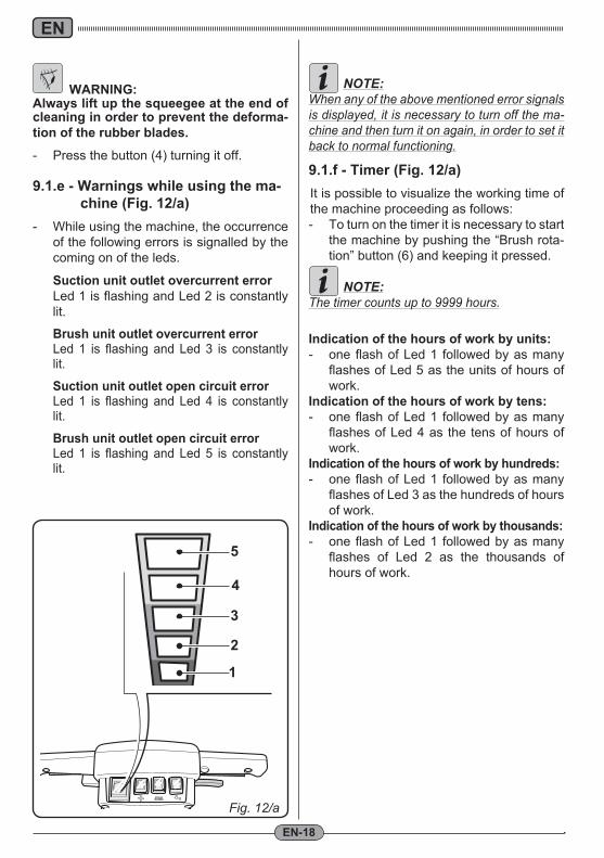
Fig. 12/a
EN
EN-18
WARNING:Always lift up the squeegee at the end of cleaning in order to prevent the deforma-tion of the rubber blades.
- Press the button (4) turning it off.
9.1.e - Warnings while using the ma-chine (Fig. 12/a)
- While using the machine, the occurrence of the following errors is signalled by the coming on of the leds.
Suction unit outlet overcurrent error Led 1 is flashing and Led 2 is constantly lit.
Brush unit outlet overcurrent error Led 1 is flashing and Led 3 is constantly
lit.
Suction unit outlet open circuit error Led 1 is flashing and Led 4 is constantly
lit.
Brush unit outlet open circuit error Led 1 is flashing and Led 5 is constantly
lit.
NOTE:When any of the above mentioned error signals is displayed, it is necessary to turn off the ma-chine and then turn it on again, in order to set it back to normal functioning.
9.1.f - Timer (Fig. 12/a)It is possible to visualize the working time of the machine proceeding as follows:- To turn on the timer it is necessary to start
the machine by pushing the “Brush rota-tion” button (6) and keeping it pressed.
NOTE:The timer counts up to 9999 hours.
Indication of the hours of work by units:- one flash of Led 1 followed by as many
flashes of Led 5 as the units of hours of work.
Indication of the hours of work by tens:- one flash of Led 1 followed by as many
flashes of Led 4 as the tens of hours of work.
Indication of the hours of work by hundreds:- one flash of Led 1 followed by as many
flashes of Led 3 as the hundreds of hours of work.
Indication of the hours of work by thousands:- one flash of Led 1 followed by as many
flashes of Led 2 as the thousands of hours of work.
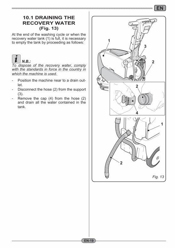
Fig. 13
1
2
31
4
2
2
EN
EN-19
10.1 DRAINING THE RECOVERY WATER
(Fig. 13)At the end of the washing cycle or when the recovery water tank (1) is full, it is necessary to empty the tank by proceeding as follows:
N.B.:To dispose of the recovery water, comply with the standards in force in the country in which the machine is used.
- Position the machine near to a drain out-let.
- Disconnect the hose (2) from the support (3).
- Remove the cap (4) from the hose (2) and drain all the water contained in the tank.
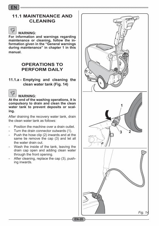
Fig. 14
3 2
1
EN
EN-20
11.1 MAINTENANCE AND CLEANING
WARNING:For information and warnings regarding maintenance or cleaning, follow the in-formation given in the “General warnings during maintenance” in chapter 1 in this manual.
OPERATIONS TO PERFORM DAILY
11.1.a - Emptying and cleaning the clean water tank (Fig. 14)
WARNING:At the end of the washing operations, it is compulsory to drain and clean the clean water tank to prevent deposits or scal-ing. After draining the recovery water tank, drain the clean water tank as follows:
- Position the machine over a drain outlet.- Turn the drain connector outwards (1).- Push the hose clip (2) inwards and at the
same tie remove the cap (3) and let all the water drain out.
- Wash the inside of the tank, leaving the drain cap open and adding clean water through the front opening.
- After cleaning, replace the cap (3), push-ing inwards.
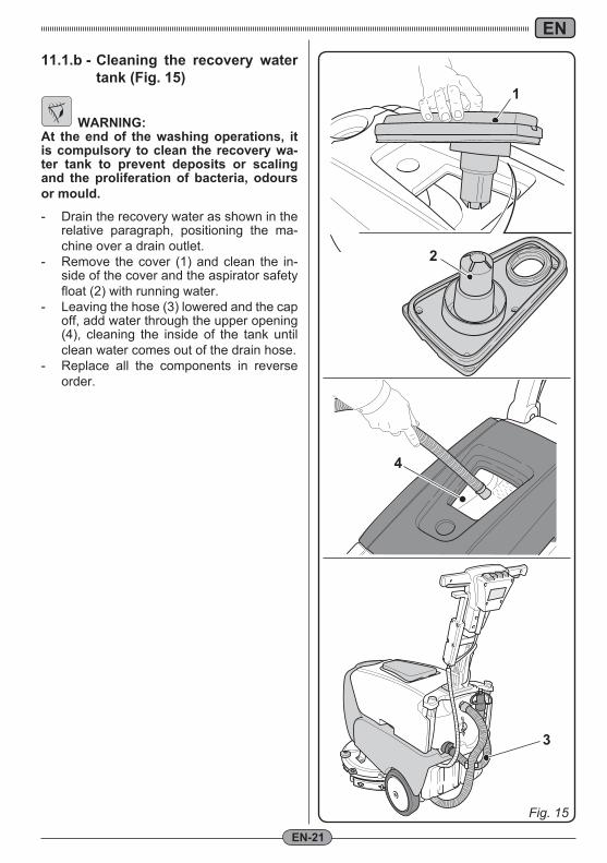
Fig. 14 Fig. 15
1
2
3
4
EN
EN-21
11.1.b - Cleaning the recovery water tank (Fig. 15)
WARNING:At the end of the washing operations, it is compulsory to clean the recovery wa-ter tank to prevent deposits or scaling and the proliferation of bacteria, odours or mould.
- Drain the recovery water as shown in the relative paragraph, positioning the ma-chine over a drain outlet.
- Remove the cover (1) and clean the in-side of the cover and the aspirator safety float (2) with running water.
- Leaving the hose (3) lowered and the cap off, add water through the upper opening (4), cleaning the inside of the tank until clean water comes out of the drain hose.
- Replace all the components in reverse order.
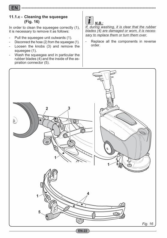
Fig. 16
11
2 3
1 4
5
EN
EN-22
11.1.c - Cleaning the squeegee (Fig. 16)In order to clean the squeegee correctly (1), it is necessary to remove it as follows:
- Pull the squeegee unit outwards (1).- Disconnect the hose (2) from the squeegee (1).- Loosen the knobs (3) and remove the
squeegee (1).- Wash the squeegee and in particular the
rubber blades (4) and the inside of the as-piration connector (5).
N.B.:If, during washing, it is clear that the rubber blades (4) are damaged or worn, it is neces-sary to replace them or turn them over. - Replace all the components in reverse
order.
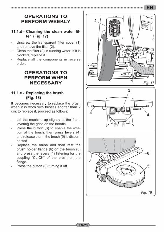
Fig. 171
2
Fig. 18
5
6
4
3
4
EN
EN-23
OPERATIONS TO PERFORM WEEKLY
11.1.d - Cleaning the clean water fil-ter (Fig. 17)
- Unscrew the transparent filter cover (1) and remove the filter (2).
- Clean the filter (2) in running water. If it is blocked, replace it.
- Replace all the components in reverse order.
OPERATIONS TO PERFORM WHEN
NECESSARY
11.1.e - Replacing the brush (Fig. 18)It becomes necessary to replace the brush when it is worn with bristles shorter than 2 cm; to replace it, proceed as follows:
- Lift the machine up slightly at the front, levering the grips on the handle.
- Press the button (3) to enable the rota-tion of the brush, then press levers (4) and release them; the brush (5) is discon-nected.
- Replace the brush and then rest the brush holder flange (6) on the brush (5) and press the levers (4) listening for the coupling “CLICK” of the brush on the flange.
- Press the button (3) turning it off.
OK
Fig. 19
1
2
3
2
Fig. 20
1
3
3
A
B
C
EN
EN-24
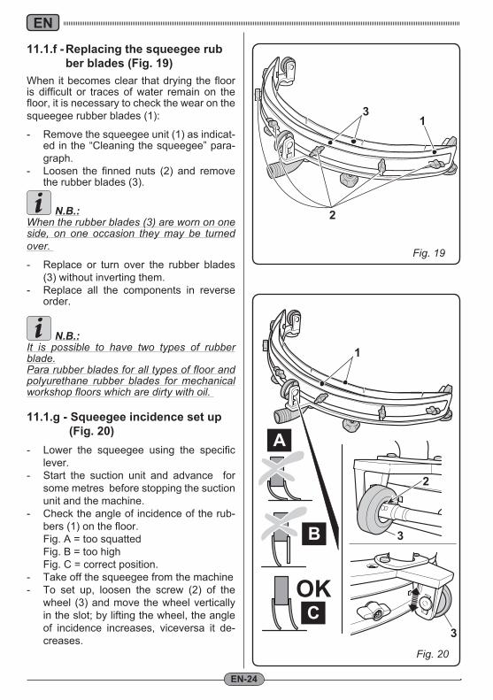
11.1.f - Replacing the squeegee rub ber blades (Fig. 19)
When it becomes clear that drying the floor is difficult or traces of water remain on the floor, it is necessary to check the wear on the squeegee rubber blades (1):
- Remove the squeegee unit (1) as indicat-ed in the “Cleaning the squeegee” para-graph.
- Loosen the finned nuts (2) and remove the rubber blades (3).
N.B.:When the rubber blades (3) are worn on one side, on one occasion they may be turned over.
- Replace or turn over the rubber blades (3) without inverting them.
- Replace all the components in reverse order.
N.B.:It is possible to have two types of rubber blade.Para rubber blades for all types of floor and polyurethane rubber blades for mechanical workshop floors which are dirty with oil.
11.1.g - Squeegee incidence set up (Fig. 20)
- Lower the squeegee using the specific lever.
- Start the suction unit and advance for some metres before stopping the suction unit and the machine.
- Check the angle of incidence of the rub-bers (1) on the floor.
Fig. A = too squatted Fig. B = too high Fig. C = correct position.- Take off the squeegee from the machine- To set up, loosen the screw (2) of the
wheel (3) and move the wheel vertically in the slot; by lifting the wheel, the angle of incidence increases, viceversa it de-creases.
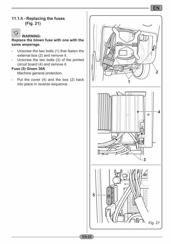
Fig. 21
4
5 E
1
2
3
EN
EN-25
11.1.h - Replacing the fuses (Fig. 21)
WARNING:Replace the blown fuse with one with the same amperage.
- Unscrew the two bolts (1) that fasten the external box (2) and remove it.
- Unscrew the two bolts (3) of the printed circuit board (4) and remove it.
Fuse (5) Green 30A Machine general protection.
- Put the cover (4) and the box (2) back into place in reverse sequence.
EN
EN-26
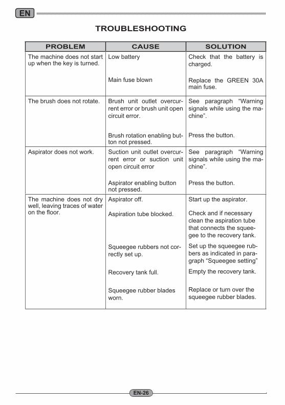
TROUBLESHOOTING
PROBLEM CAUSE SOLUTIONThe machine does not start up when the key is turned.
Low battery
Main fuse blown
Check that the battery is charged.
Replace the GREEN 30A main fuse.
The brush does not rotate. Brush unit outlet overcur-rent error or brush unit open circuit error.
Brush rotation enabling but-ton not pressed.
See paragraph “Warning signals while using the ma-chine”.
Press the button.
Aspirator does not work. Suction unit outlet overcur-rent error or suction unit open circuit error
Aspirator enabling button not pressed.
See paragraph “Warning signals while using the ma-chine”.
Press the button.
The machine does not dry well, leaving traces of water on the floor.
Aspirator off.
Aspiration tube blocked.
Squeegee rubbers not cor-rectly set up.
Recovery tank full.
Squeegee rubber blades worn.
Start up the aspirator.
Check and if necessary clean the aspiration tube that connects the squee-gee to the recovery tank.
Set up the squeegee rub-bers as indicated in para-graph “Squeegee setting”
Empty the recovery tank.
Replace or turn over the squeegee rubber blades.
EN
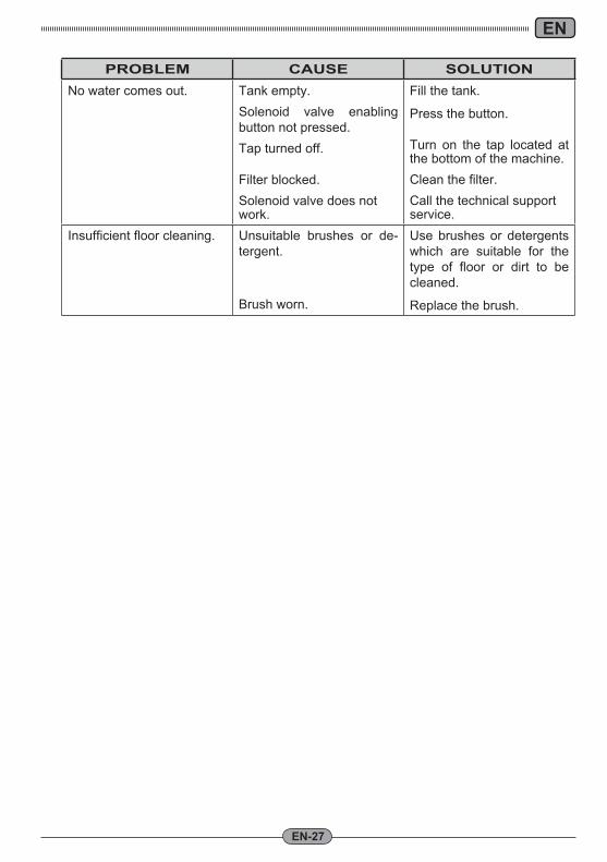
EN-27
PROBLEM CAUSE SOLUTIONNo water comes out. Tank empty.
Solenoid valve enabling button not pressed. Tap turned off.
Filter blocked.Solenoid valve does not work.
Fill the tank.
Press the button.
Turn on the tap located at the bottom of the machine.Clean the filter.Call the technical support service.
Insufficient floor cleaning. Unsuitable brushes or de-tergent.
Brush worn.
Use brushes or detergents which are suitable for the type of floor or dirt to be cleaned.
Replace the brush.
EN
EN-28
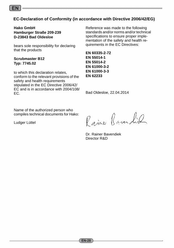
Hako GmbHHamburger Straße 209-239D-23843 Bad Oldesloe
bears sole responsibility for declaring that the products
Scrubmaster B12Typ: 7745.02
to which this declaration relates, conform to the relevant provisions of the safety and health requirements stipulated in the EC Directive 2006/42/EC and is in accordance with 2004/108/EC.
Name of the authorized person who compiles technical documents for Hako:
Ludger Lüttel
Reference was made to the following standards and/or norms and/or technical specifications to ensure proper imple-mentation of the safety and health re-quirements in the EC Directives:
EN 60335-2-72EN 55014-1EN 55014-2EN 61000-3-2EN 61000-3-3EN 62233
Bad Oldesloe, 22.04.2014
Dr. Rainer BavendiekDirector R&D
EC-Declaration of Conformity (in accordance with Directive 2006/42/EG)

Hako GmbH · Hamburger Str. 209-239 · D-23843 Bad Oldesloe +49 4531 806-0 · Fax +49 4531 806-338
88-1
0-29
54 -
3100
-04
Spitzentechnik für eine saubere und schönere UmweltAdvanced Technology for a Cleaner, Better Environment


![openp2pdesign.org 1.1 [en Castellano]](https://img.pdfslide.us/doc/110x75/577dad3c1a28ab223f8ef5fb/openp2pdesignorg-11-en-castellano.jpg)