Embed Size (px)
Citation preview

Instruction Manual
Free Standing
Jib Crane
Model A360 XXXX
Serial Number XX-XXXXX
Date

Krane-King ® THE CALDWELL GROUP
2

Krane-King ® THE CALDWELL GROUP
3
Your new KRANE-KING®, free standing Jib Crane is for specific tasks, withstanding forces based on the unit’s rated capacity when loaded correctly. The installation, operation, and maintenance instructions in this manual are typical of the KRANE-KING®, free standing Jib Crane. Please note that your Jib Crane may differ from the pictorial examples in this manual. Use the following guidelines in this manual for your protection, and for optimal operation of your equipment. The safety precautions listed in the man-ual are not all-inclusive. The owner/user is responsible for understanding and acting according to indus-try standards and any other required local, city, state, or federal regulations. In addition, refer to the Manufacturer’s instruction manuals for more detailed product information on other attachments or com-ponents used with your equipment. This manual contains important information to help you install, operate, maintain, and service your Jib Crane from The Caldwell Group. We recommend that you study its contents thoroughly before putting the crane into use. Properly installing, applying correct operating procedures, and by practicing the rec-ommended inspection and maintenance suggestions, you can expect maximum service from your equipment. When ordering replacement parts, include your unit’s model and serial number with your order. This information is located the manual’s front cover and on your Jib Crane’s I.D. tag (see Caldwell I.D. tag, page 35). The following information and recommendations in this manual are guidelines for installing, operating, inspecting, and maintaining your Jib Crane and general in nature. If specific information is required and not in this manual, contact THE CALDWELL GROUP: Toll Free (800) 628-4263, Customer Service (815) 229-5667 fax (815) 229-5686 www.caldwellinc.com
PREFACE

Preface 3
Safety Information 5
Installation
Supporting Structure 11
Mast Installation 12
Taper Bearing Installation 13
Head Installation 14
Roller Shim Installation 15
Boom Installation 16
Head Beam Shim Installation 18
Safety Bar and Safety Pipe Installation 19
Optional Accessories 20
Slip Ring Assembly 21
Tagline Kit 22
Trolley and Hoist 23
Rotational Stops 24
Anchor Bolts 24
Roto-Max and Roto-Mate 25
Jib Crane Motorization Instructions-ROTO-MATE™ 26
Lubrication 34
Tag and Decal Location 35
Inspection & Maintenance 36

Krane-King ® THE CALDWELL GROUP
5
DANGER indicates a hazardous Situation which, if not avoided, will result in death or serious injury.
CAUTION, used with the safety alert symbol, indicates a hazardous situation which, if not avoided, could result in minor or moderate injury.
This is the safety alert symbol. It is used to alert you to potential
hazards. Obey all safety messages that follow this symbol to avoid possible injury or death.
WARNING indicates a hazardous situation which, if not avoided, could result in death or serious injury.
SAFETY INFORMATION
SAFETY

Krane-King ® THE CALDWELL GROUP
6
SAFETY
The fundamental objective of the following safety suggestions is to protect authorized, qualified persons responsible for installation, operations, and inspection of the A360 Jib Crane from serious injury or death. The owner or user is responsible for providing all proper devices, tools and methods that may be necessary to effectively protect each employee from recognized hazards, during installation, operation, maintenance, or servicing. The safety precautions stated in this manual are not all-inclusive. The owner/user is responsible for understanding and acting according to industry standards and regulations—and any other applicable local, city, state, or fedral ordinances.
GENERAL
Authorized, qualified individuals need comprehensive training in the use of protective equipment, safe-guards, and safe operation of the A360 Jib Crane.
Permit only authorized, qualified people to operate and maintain your A360 Jib Crane.
Personal protective equipment is required whenever there are hazards that can do bodily harm through physical contact. The construction requirements of all personal protective equipment must be concurrent to the work performed.
PERSONAL PROTECTION
TRAINING
SAFETY INFORMATION

Krane-King ® THE CALDWELL GROUP
7
Read this manual before preparing the support structure, installing, operating, or inspecting the A360 Jib Crane.
Allow only qualified persons to install, operate, inspect, maintain, and service your Model A360 Jib Crane.
Check your unit upon arrival, ensuring no damage or lost parts occurred during transit. Contact the carrier’s agent, reporting loss or damage.
Consult a qualified, professional engineer to assess the supporting structure stability, which will support the weight of the hoisting equipment, platform, and load; and obtain written approval. The supporting structure’s stability deter-mines whether or not the jib crane is secure and plumb.
Designate only qualified persons to properly erect the jib crane and platform.
Inspect equipment before installing, ensuring possession of all components.
Install and plumb the mast .
Confirm the unit is assembled correctly.
Inspect the crane, confirming all:
equipment is plumb
fasteners are tight
tapered bearing, located on the mast spindle, is well lubricated .
Before Installing
Before initial operation
Installing
Receiving
SAFETY INFORMATION
WARNINGWARNING

Krane-King ® THE CALDWELL GROUP
8
SAFETY INFORMATION
WARNINGWARNING
Verify each operator is qualified or certified.
Request each operator to demonstrate proper hoisting techniques, using the jib crane.
Verify the travel path is clear.
Test the jib crane before initial use, confirming proper trolley movement.
Barricade people from swing zones, fall zones, and crush zones.
Confirm the combined weight of the load and hoist does NOT exceed the crane’s rated capacity.
Confirm all lifting devices: chains, ropes, or slings are free from twists, kinks, or any damages.
Confirm all lifting devices: chains, ropes, slings, are completely seated in the hook.
Center the hoist in-line with the load’s center of gravity.
Inspect the load, making sure nothing can fall from the load, during the lifting or transporting cycle.
Verify all equipment adjustments are correct and secure.
Do NOT lift loads over people.
Do NOT lift people.
Prohibit any person from riding on the load or crane.
Obey stop signals from anyone.
Lift or transport only properly balanced loads.
Confirm the load is ready for the lifting or transporting cycle.
Verify the transport area is clear of people and physical obstructions before the lifting cycle begins.
Operating Practices

Krane-King ® THE CALDWELL GROUP
9
Lifting Cycle
Departing
Inspecting &
Maintaining
Pick up all loads with the hoist line vertical.
Start lifting the load slowly and gently.
Raise, lower, or transport the load ONLY over specified areas.
Avoid swinging loads—Transport the load slowly.
Do NOT use shock loading or side loading.
Do NOT drag loads along the ground.
Prohibit people from standing under a suspended load.
Prohibit operators from leaving a suspended load unattended.
Set the load down gently.
Establish a regular inspection and maintenance schedules:
—operator visually examines before and during each lift
—visual examination by operator or designated person:
1. Normal Service—monthly
2. Heavy Service—weekly to monthly
3. Severe Service—daily to weekly
4. Special or Infrequent Service—a qualified person shall recommend before and after each occurrence
—visual inspection by a qualified person,
recording external conditions.:
1. Normal Service—yearly
2. Heavy Service—semi-annually
3. Severe Service—quarterly
4. Special or Infrequent Service—a qualified person shall recommend before and after each occurrence
Keep the jib crane clean and operational at all times.
Disconnect all power when the crane is not in use.
SAFETY INFORMATION
WARNINGWARNING

Krane-King ® THE CALDWELL GROUP
10
Inspecting
Modifying
Keeping Records
Establish a regular inspection schedule.
Inspect the jib crane regularly for malfunctions, wear, damages, or missing parts.
Inspect equipment regularly for worn, damaged, or missing: ID tag, product safety labels, rated capacity, or weight markings.
Prohibit warning label and identification tag removal or concealment.
Contact The Caldwell Group for complimentary replacement tags: ID tag, product safety labels, rated capacity, or weight markings.
Remove the jib crane from service and tag the jib crane “OUT OF SERVICE” when regular inspection reveals :
-malfunctions
-wear
-damage
-missing parts
-worn, damaged, or missing —
ID tag
product safety labels
rated capacity markings.
Secure written approval from The Caldwell Group before making any alterations or
modifications to the jib crane.
Keep complete records on your jib crane: instructions, inspections, maintenance,
service, and modifications.
SAFETY INFORMATION
WARNINGWARNING

Krane-King ® THE CALDWELL GROUP
11
INSTALLATION Model A360 Free Standing Jib Crane
Upon receipt of your new Model A360, Jib Crane, fully inspect to confirm no parts were lost or damaged, during transit. The A360 is shipped in two sections: 1. the mast, 2. the head and boom attached, The hardware is packed separately. If a hoist package is a selected feature on your Jib Crane, it is also packed separately. Confirm all the tags and decals are securely fixed to your unit and clearly legible (see Tag & Decal Location drawing, pg 35). Permit only authorized, qualified persons, to install, operate, maintain, and service the A360 Jib Crane.
Supporting Structure Consult a qualified, professional engineer to assess and provide precise, supporting structure plans for your A360 Jib Crane. Prepare the supporting structure per professional instructions. Use a template to install the anchors in the correct orientation. Then, match it up to the Mast Base Plate and rotate as required. Soil Foundation The A360 Jib Crane requires a minimum of 2,500 pounds of soil pressure per square foot. Concrete Foundation The A360 Jib Crane requires a minimum of 3,000 pounds of compressive strength per square inch. Contact the concrete supplier for required cure times, achieving maximum concrete compressive strength. Grout The base plate must have thorough contact with the supporting structure. Allow approximately one inch of grout (non-shrinking, high machinery type) between the base plate and the supporting structure surface. Grout shall completely support the base plate contact area.
Base Plate

Krane-King ® THE CALDWELL GROUP
12
MAST INSTALLATION
WARNINGWARNING
Correctly plumb the Mast. When the Mast is plumbed, an assembled jib crane independently rotates, swings, or drifts with or without a load, causing death, serious injury, property damage, or all three. Do NOT plumb the Mast with a level. Use a commercial plumb fixture and plumb line.
Plumb the Mast 4. Clamp a plumb fixture securely to the Mast Spindle. 5. Secure and drop a plumb line from the plumb fixture. 6. Position the plumb line 3 inches out from the Mast Pipe
vertical edge at two locations: a. 1 inch below the Top Mast Plate lip b. at the approximate Roller center line 7. Position and measure plumb line every 60° around the
Mast, ensuring the Mast is exactly vertical. 8. Tighten alternate hold down hardware until the Mast is
plumb. 9. After all anchor bolts are tight, re-check and verify the
Mast is plumb every 60 degrees.
Position the Mast 1. Position the Mast on top of the supporting
structure.
2. Attach the Mast to the supporting structure.
3. Do NOT over tighten hold down hardware
because adjustments may be needed later.

Krane-King ® THE CALDWELL GROUP
13
WARNINGWARNING
1. Pack the taper bearing with grease.
2. Place the taper bearing on the Mast Spindle , using the correct orientation.
TAPER BEARING INSTALLATION
Taper Bearing
Mast Spindle
Mast Top Plate
CORRECT INCORRECT
Attach the taper bearing to the mast before connecting the Head

Krane-King ® THE CALDWELL GROUP
14
HEAD INSTALLATION
1. Set the Head on the Mast.
3. Lower the Head onto the Mast.
2. Line up the center of the Head’s medium bearing cup with the center of the Mast Spindle.

Krane-King ® THE CALDWELL GROUP
15
1. Add Roller Shims, if necessary, to assure the Head is plumb.
2. Loosen the Roller Shim Mounting Bolts. 3. Turn the Adjustment Screw clockwise,
which tightens the Adjustment Screw and widens the gap between the Roller Support Channel and the Roller Shim Assembly.
4. Measure the gap, making sure the gap is
wide enough for the shim to slide into place.
5. Insert the Roller Shim. Additional shims
may be required. 6. Turn the Adjustment Screw counter-
clockwise, which loosens the Adjustment Screw and relieves the pressure on the Roller Support Channel.
7. Tighten the Roller Shim Mounting Bolts
when the Head is plumb. 8. After the crane is completely assembled,
use the Roller Shim Adjustment Screw when the crane is load free.
ROLLER SHIM INSTALLATION
WARNINGWARNING
Remove the load from the crane. The adjustment screw is not designed to support a loaded crane.

Krane-King ® THE CALDWELL GROUP
16
1. Set the Boom on the Head. 2. Line up the Boom and Head Rear Mounting Plate holes. 3. Tighten the bolts. 4. Do NOT over-tighten because adjustments may be needed later.
BOOM INSTALLATION

Krane-King ® THE CALDWELL GROUP
17
WARNINGWARNING
CORRECT SPAN 300
BOOM INSTALLATION
Avoid deflection.
Position the boom— SPAN I 300 = distance above horizontal.
Do NOT position the Boom exactly at the head’s horizontal line.
Do NOT position the Boom the head’s horizontal line.
U P
XX TON CAP.
Crane Height
HORIZONTAL(Top of Head)
SPAN
MastCenter Line
XX TON CAP.
HORIZONTAL(Top of Head)
Crane Height
D O W N
XX TON CAP.
HORIZONTAL(Top of Head)
Crane Height
Position the Boom above the head’s horizontal line:
INCORRECT
INCORRECT
SPAN 300

Krane-King ® THE CALDWELL GROUP
18
HEAD BEAM SHIM INSTALLATION
1. Add Front Beam Shims, adjusting the Boom position above horizontal, . 2. Tighten the bolts: Front Beam Mounting Bolts, Boom and Head Rear Mounting Plate Bolts. 3. Do NOT over-tighten because adjustments may be needed later. 4. Verify the crane is plumb and the boom is above horizontal, .
5. Make adjustments as necessary. 6. Tighten the bolts: Front Shim Bolts, Boom and Head Rear Mounting
Plate Bolts, when the crane is plumb and the boom is above horizontal, .
SPAN 300
SPAN 300
SPAN 300

Krane-King ® THE CALDWELL GROUP
19
SAFETY BAR AND SAFETY PIPE INSTALLATION
Safety Bar and Safety Pipe
1. Insert the Safety Bar and Safety Pipe through the Head.
2. Fasten securely on both sides of the Head.

Krane-King ® THE CALDWELL GROUP
20
OPTIONAL ACCESSORIES
HE
AD
MA
ST
4411
14W
AS
HE
RE
AE
AB
OL
T-H
EX
HE
AD
13E
AB
AS
E,
TO
P C
OL
LE
CT
OR
12E
AC
OL
LE
CT
OR
, TO
P E
NT
RY
11
UM
CO
LL
EC
TO
R T
OP
EN
TR
Y
O
PT
ION
QT
YIT
EM
QT
YIT
EM
1091
PA
INT
, 2
CO
AT
S
JU
NC
TIO
N B
OX
, N
EM
A
4X
ST
AIN
LE
SS
OU
TD
OO
R O
PT
ION
S
EA
EA
UMEA
EA
EA
EA
EA
EA
EA
87654321
11*11131
(SE
E N
OT
E B
EL
OW
)H
OIS
T P
AC
KA
GE
AN
CH
OR
BO
LT
SC
OL
LE
CT
OR
, B
OT
TO
M E
NT
RY
RO
TO
-MA
XR
OT
O-M
AT
ES
TO
P B
LO
CK
TA
G L
INE
KIT
, W
EL
D-O
NU
MD
ES
CR
IPT
ION
QT
YIT
EM
5
7
2
34
1
1112
1413
NO
TE
:D
O N
OT
US
E S
TO
PS
W
ITH
CO
LL
EC
TO
R
OP
TIO
N.
OP
TIO
N
HE
AD
RO
TA
TIO
NA
LS
TO
P B
LO
CK
IT
EM
# 2
OP
TIO
N
RO
TA
TIO
N S
TO
PS
,IT
EM
#2
LO
CA
TE
D B
Y
CU
ST
OM
ER
AN
DF
EIL
D W
EL
D T
O S
UIT
OP
TIO
N
OP
TIO
NOP
TIO
N
Krane-King ® THE CALDWELL GROUP
21
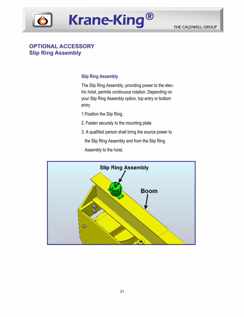
OPTIONAL ACCESSORY Slip Ring Assembly
Slip Ring Assembly
The Slip Ring Assembly, providing power to the elec-tric hoist, permits continuous rotation. Depending on your Slip Ring Assembly option, top entry or bottom entry
1.Position the Slip Ring.
2. Fasten securely to the mounting plate.
3. A qualified person shall bring the source power to
the Slip Ring Assembly and from the Slip Ring
Assembly to the hoist.

Krane-King ® THE CALDWELL GROUP
22
OPTIONAL ACCESSORY Tagline Kit
TAG LINE KIT (1)
Tag Line Bracket (Ref)(2)
Eyebolt1/4-20 X 4.00 LG (2)
1/4-20 Hex Nut(4)
1/4" Flat Washer(4)
1/4" Lockwasher(2)
Closed End S Hook(5)
1/8" Wire Rope Clip(4)
1/8" Ø Aircraft Cable(1)
Using a Tagline Kit, prevents the power cord from tangling and dropping 1. Locate the tagline position on the boom 2. Field weld the tagline brackets to suit. 3. Follow AWS D1.1 standards. 4. Attach the remaining tagline kit components. 5. Make sure bolts are tight and aircraft cable is taught.

Krane-King ® THE CALDWELL GROUP
23
OPTIONAL ACCESSORY Hoist
When the hoist is attached, maintain the boom’s position. If the boom is at
horizontal or below horizontal, shim as needed.
WARNINGWARNING
Trolley and Hoist
1. Place the trolly on the boom flange.
2. Attach the hoist to the trolley.
3. Verify the boom is above horizontal after the hoist is attached.
4. Adjust as needed, maintaining the boom’s above horizontal position.
XX TON CAP.
Hoist
Shim
HORIZONTAL(Top of Head)
U P

Krane-King ® THE CALDWELL GROUP
24
OPTIONAL ACCESSORY
Anchor Bolts
Rotational Stop Blocks
J-type anchor bolts with nuts and washers are for mounting the mast to the foundation.
Rotational stop blocks limit the cranes rotational travel. If rotational stop blocks are a selected option, then, the stop blocks are shipped loose to be field welded to suit.

Krane-King ® THE CALDWELL GROUP
25
Roto-Max or Roto-Mate If the jib crane motorization package is a selected feature, the motor will be either a Roto-Max or Roto-Mate, depending on the size and rated ca-pacity of your crane. 1. Bolt the Roto-Max or Roto_Mate to the back of the Head. 2. Make sure bolts are tight. 3. Follow the manufacturer’s instructions for more detail information.
OPTIONAL ACCESSORY Roto-Max or Roto-Mate

Krane-King ® THE CALDWELL GROUP
26

Krane-King ® THE CALDWELL GROUP
27

Krane-King ® THE CALDWELL GROUP
28

Krane-King ® THE CALDWELL GROUP
29

Krane-King ® THE CALDWELL GROUP
30

Krane-King ® THE CALDWELL GROUP
31

Krane-King ® THE CALDWELL GROUP
32

Krane-King ® THE CALDWELL GROUP
33

Krane-King ® THE CALDWELL GROUP
34
LUBRICATION
1. Establish a lubrication schedule based on: a. environmental conditions b. operational frequency 2. Keep the Mast tapered bearing well lubricated.
WARNINGWARNING
Lubricate the tapered bearing before initial operation.

Krane-King ® THE CALDWELL GROUP
35
ID Tag and Product
When the markings, identification tag, or product safety labels are damaged or missing: 1. Remove the unit from service, 2. Tag the unit with an “OUT of SERVICE” label, 3. contact The Caldwell Group for complimentary replacements.
MARKINGS, ID TAG, & PRODUCT SAFETY LABELS
Warning read-understand
instruction manual
6
Made in the USA
5
Parts and Service
4
3
Product identification tag
2
Caldwell Logo 1
XX TON CAP Unit Rated Capacity
Warning Do NOT exceed
rated capacity
7
8
Warning Pinch Points
A360 JIB CRANE
XXTON CAP.
MODIFICATIONS TO YOUR LIFTING EQUIPMENT WITHOUT PRIOR
WRITTEN APPROVAL FROM THE CALDWELL GROUP, INC.
VOIDS YOUR WARRANTY.

Krane-King ® THE CALDWELL GROUP
36
Before servicing the jib crane, de-energize and disconnect all power .
WARNINGWARNING
Regular inspections may be more or less frequent for your crane, depending on the severity of use and site conditions. Regular inspections also serve as maintenance checks and identifies the need for repair or replacements. Three inspection intervals for regular service: Every Lift Inspection—operator or designate person visually examines, determining safe crane operation a. before the shift starts b. before each lift c. during each lift Frequent Inspection—operator or designated person visually examines, determining safe crane operation a. Normal Service…..monthly b. Heavy Service……weekly to monthly c. Severe Service……daily to weekly Periodic Inspection—qualified person visually inspects and evaluates units external condition, determining unit repair or component replacements a. Normal Service…...yearly (unit in place) b. Heavy Service…….semi-annually (determining further detailed inspection) c. Severe Service…...quarterly (determining further detailed inspection) d. Special or Infrequent Service—recommended by a qualified person Regularly scheduled inspection and maintenance assures reliable operation.
INSPECTION and MAINTENANCE

Krane-King ® THE CALDWELL GROUP
37
Inspect the entire crane
Check for: Condition:
Vertical Straightness Crane must be plumb
Horizontal Boom Position
Boom must be slightly above horizontal—with
out a load—SPAN I 300
Structural Damage Free from distortion, cracks, excessive wear, dents, bends, corrosion
Roller Assembly Full contact with the Mast , bolts are tight, prop-erly adjusted, free from wear, bends, cracks
Guarding Tightly secured and stable
Hooks Free from distortion, cracks, excessive throat openings
Wire Ropes-Hoist Cable-Pendant Cable Free from cracks, twists, kinks, splits, corrosion,
looseness
All Welds Free from distortion, cracks, bends
Paint Cracking or flaking may indicate metal fatigue
Hardware:
Bolts Fasteners Pins
Rollers Bearings Washers
nuts
Free from looseness, deformation, corrosion, cracks, wear—make sure all bolts and fasteners are secure.
Performance Indicators Free from excessive noise and vibration, main-tains regular operating speed
Freedom of Rotation Rotational travel is smooth
Electrical Components
Wiring is free from cracks and splits—Insulation
Is tight and free from corrosion-controls are free from deterioration and damage
Lubrication Keep Mast Tapered Bearing well lubricated

The Caldwell Group, Inc.5055 26th Avenue Phone (815) 229-5667Rockford, IL 61109 Toll Free (800) 628-4263www.caldwellinc.com Fax (815) 229-5686
A360 (Rev_00 Feb 2010)