Embed Size (px)
Citation preview
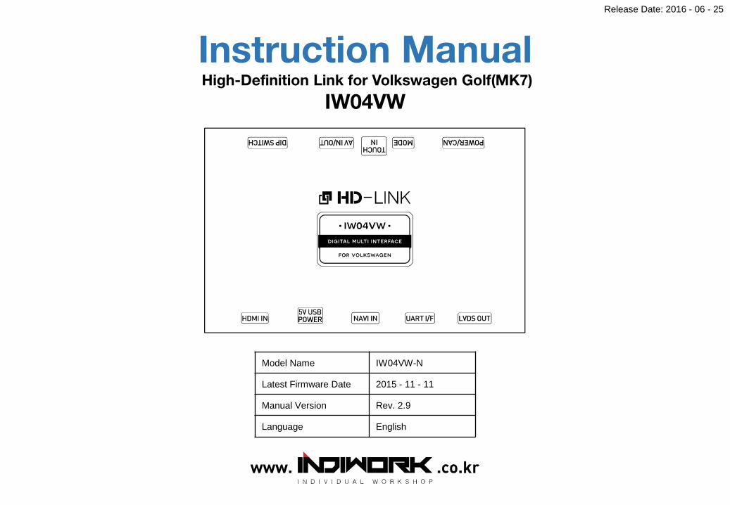
Instruction ManualHigh-Definition Link for Volkswagen Golf(MK7)
IW04VW
Model Name IW04VW-N
Latest Firmware Date 2015 - 11 - 11
Manual Version Rev. 2.9
Language English
Release Date: 2016 - 06 - 25
Contents
• Cautions
• Dimension & Exterior
• Components & Optional parts
• Full Installation Diagram
• HDMI Connection Diagram
• Navigation Connection Diagram
• Compatibility Chart for Navigation(GPS) box models
• LVDS Connection Diagram
• Body Connector specifications
• Car Compatibility Chart
• Activation by original buttons
• DIP Switch Settings
• Settings
1. Enter into the setting menu
2. HDMI mode settings
3. NAVI mode settings
4. Rear view camera settings
5. AV1(Front view camera) settings
6. Automatic activation function(AV1)
7. AV2 settings
8. System settings
9. System information
____________________________________________________________ 3
_________________________________________________ 4
_________________________________________ 5
______________________________________________ 7
____________________________________________ 9
_________________________ 10
___________________ 12
___________________________________________ 13
_______________________________________ 14
______________________________________________ 15
________________________________________ 16
_________________________________________________ 17
____________________________________ 18
___________________________________________ 19
____________________________________________ 19
_____________________________________ 20
________________________________ 20
_____________________________ 21
___________________________________________________ 21
_______________________________________________ 22
____________________________________________ 22
3
IW04VW-related
• You should check the names and colors of each wires exactly, before you connect the wires.
ex) CAN HIGH: White wires / CAN LOW: Blue wires
• The ‘POWER / CAN Cable’ should always be connected last and be disconnected first.
• The 'Mode Switch' is an optional part to change modes forcibly without CAN-BUS.
Generally, the CAN-BUS wires are connected for changing modes by original buttons.
• When the reverse gear is not detected by CAN-BUS,
the 'REVERSE 12V IN wire’ should be spliced with 12V power of reverse light.
HDMI device-related
• HDMI mode accepts general-screen resolution of HDMI devices(1080P / 1920*1080).
If screen size of HDMI does not fit on the monitor, should adjust screen size & position in 'settings mode'.
• Generally, '5V 1A Power output(5V USB POWER)' is a standard voltage for charging smartphone.
If you need higher voltage than 5V, you should add a separate power supply.
Navigation(GPS) box-related
• When you connect the power wires(B+, ACC) to the navigation(GPS) box,
the ‘NAVI 12V OUT' wire supported by IW04VW should be spliced with an ACC wire of navigation box.
• After installation is done, select an applicable navigation(GPS) box model in the 'Navigation model selection
menu' of setting mode.
• The navigation box should be powered off before unplugging the HDMI cable.
Cautions
4
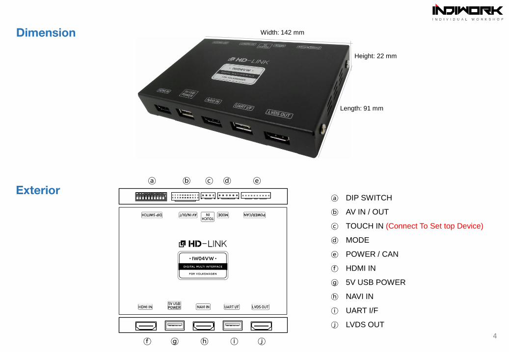
ⓐ ⓑ ⓒ ⓓ ⓔ
ⓕ ⓖ ⓗ ⓘ ⓙ
ⓐ DIP SWITCH
ⓑ AV IN / OUT
ⓒ TOUCH IN (Connect To Set top Device)
ⓓ MODE
ⓔ POWER / CAN
ⓕ HDMI IN
ⓖ 5V USB POWER
ⓗ NAVI IN
ⓘ UART I/F
ⓙ LVDS OUT
Width: 142 mm
Length: 91 mm
Height: 22 mm
Exterior
Dimension
5
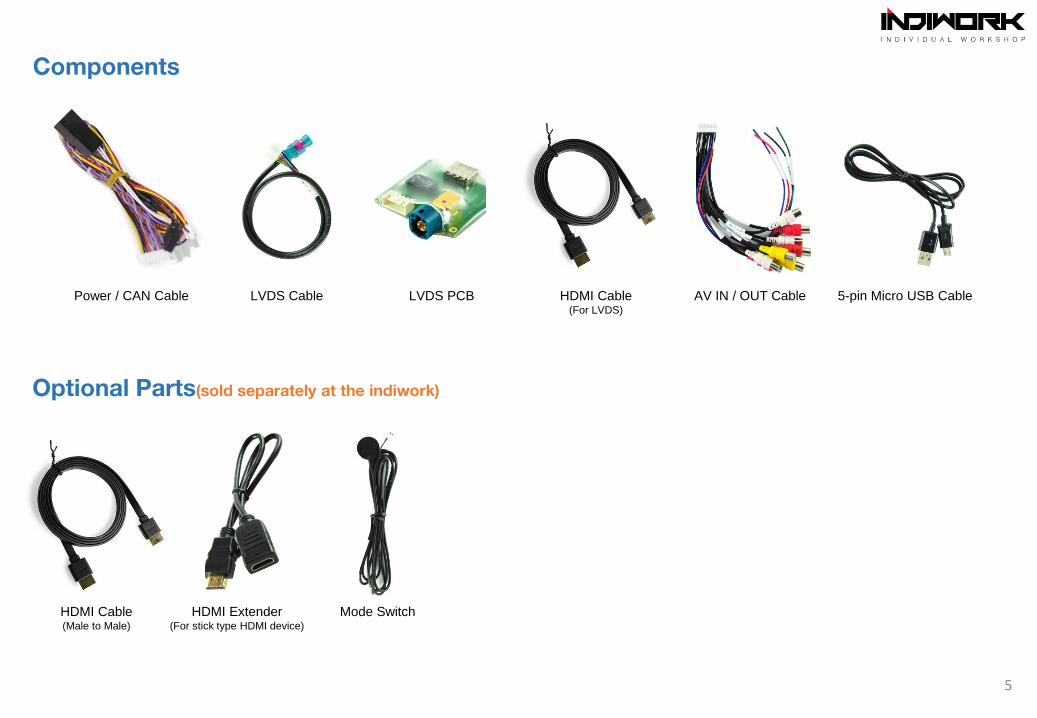
Power / CAN Cable LVDS Cable LVDS PCB HDMI Cable(For LVDS)
AV IN / OUT Cable 5-pin Micro USB Cable
Components
Optional Parts(sold separately at the indiwork)
Mode SwitchHDMI Extender(For stick type HDMI device)
HDMI Cable(Male to Male)
External Rear View
Camera
Audio(AUX) Output of
Navigation Box
Auxiliary(AUX)
Input of the car
External Front View
Camera
AV device
(ex: DTV Box, Divx)
HDMI
HDMI
HDMI
HDMI
HDMI USB
7
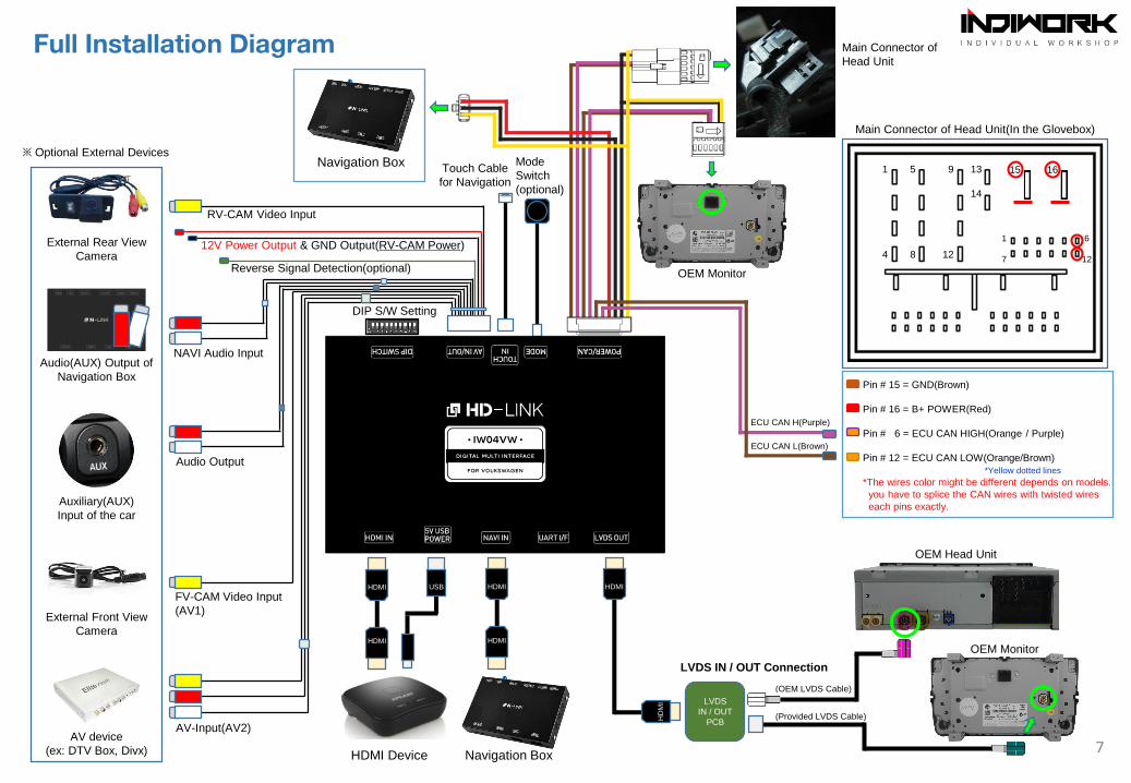
LVDS IN / OUT Connection
OEM Head Unit
LVDS
IN / OUT
PCB
HD
MI
Main Connector of Head Unit(In the Glovebox)
1
4
5
8
9
12
13
14
15 16
1 6
7 12
Pin # 15 = GND(Brown)
Pin # 16 = B+ POWER(Red)
Pin # 6 = ECU CAN HIGH(Orange / Purple)
Pin # 12 = ECU CAN LOW(Orange/Brown)
*Yellow dotted lines
*The wires color might be different depends on models.
you have to splice the CAN wires with twisted wires
each pins exactly.
ECU CAN H(Purple)
ECU CAN L(Brown)
(OEM LVDS Cable)
(Provided LVDS Cable)
OEM Monitor
Full Installation Diagram
※ Optional External Devices
RV-CAM Video Input
DIP S/W Setting
12V Power Output & GND Output(RV-CAM Power)
Reverse Signal Detection(optional)
NAVI Audio Input
HDMI Device
FV-CAM Video Input
(AV1)
Audio Output
AV-Input(AV2)
Mode
Switch
(optional)
Navigation Box
OEM Monitor
Main Connector of
Head Unit
Navigation BoxTouch Cable
for Navigation
HDMI
HDMI(Female)
USB
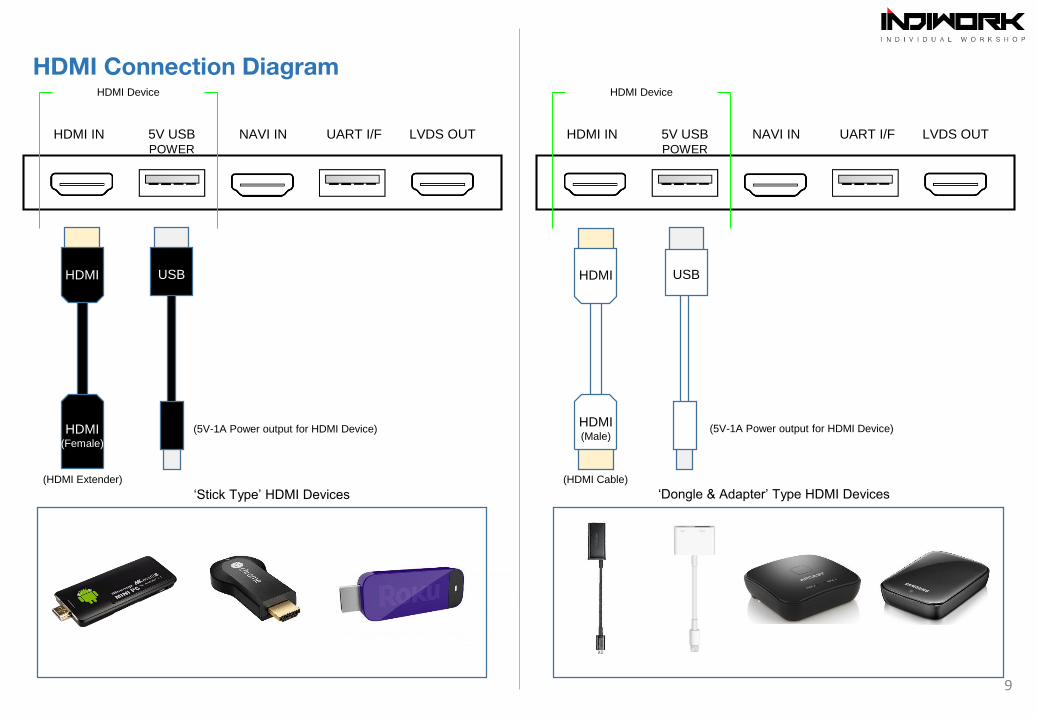
‘Stick Type’ HDMI Devices
HDMI IN 5V USBPOWER
NAVI IN UART I/F LVDS OUT
HDMI Device
HDMI IN 5V USBPOWER
NAVI IN UART I/F LVDS OUT
HDMI Device
USBHDMI
HDMI(Male)
‘Dongle & Adapter’ Type HDMI Devices
HDMI Connection Diagram
(5V-1A Power output for HDMI Device) (5V-1A Power output for HDMI Device)
(HDMI Extender) (HDMI Cable)
9
HDMI IN 5V USBPOWER
NAVI IN UART I/F LVDS OUT HDMI IN 5V USBPOWER
NAVI IN UART I/F LVDS OUT
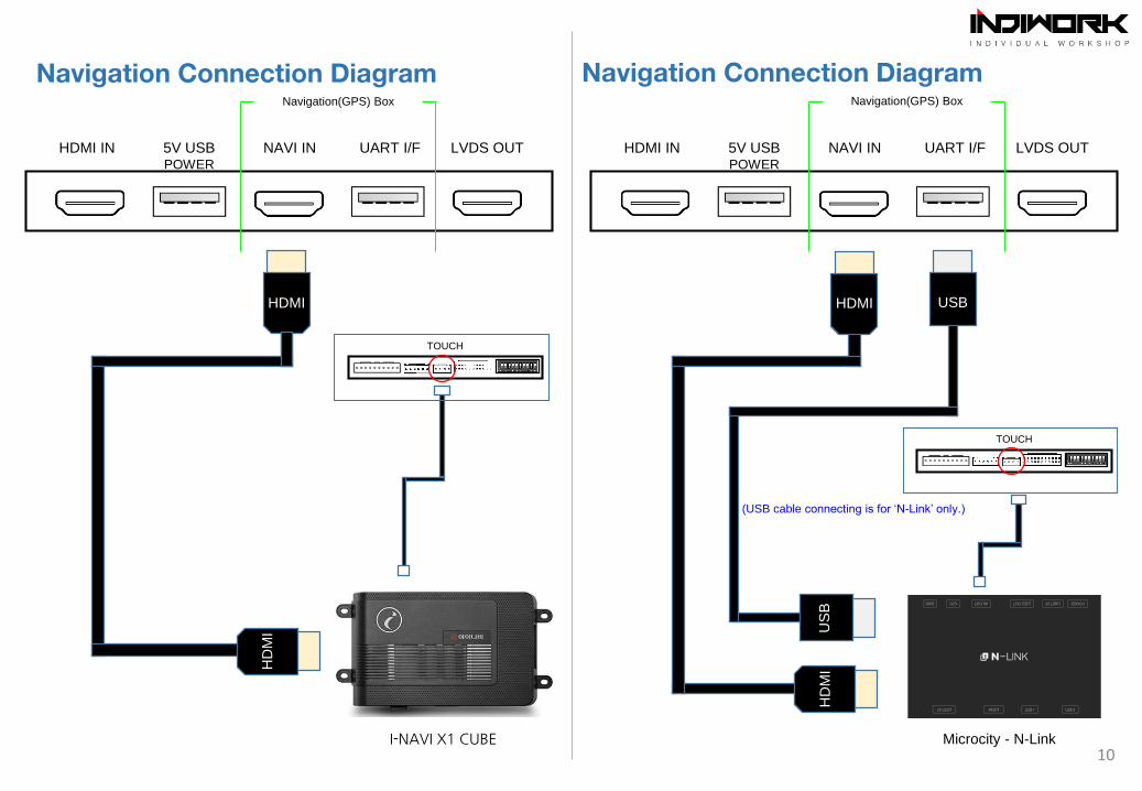
Navigation Connection Diagram Navigation Connection Diagram
Navigation(GPS) Box Navigation(GPS) Box
10Microcity - N-Link
HDMI
HD
MI
USB
US
B
(USB cable connecting is for ‘N-Link’ only.)
HDMI
I-NAVI X1 CUBE
HD
MI
TOUCH
TOUCH
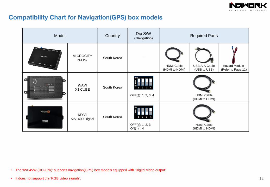
Model CountryDip S/W
(Navigation)Required Parts
MICROCITY
N-LinkSouth Korea -
HDMI Cable
(HDMI to HDMI)
USB A-A Cable
(USB to USB)
Hazard Module
(Refer to Page.11)
iNAVI
X1 CUBESouth Korea
OFF(↑): 1, 2, 3, 4 HDMI Cable
(HDMI to HDMI)
MYVI
MS1400 DigitalSouth Korea
OFF(↓): 1, 2, 3
ON(↑) : 4
HDMI Cable
(HDMI to HDMI)
Compatibility Chart for Navigation(GPS) box models
• The 'IW04VW (HD-Link)' supports navigation(GPS) box models equipped with 'Digital video output'.
• It does not support the 'RGB video signals'. 12
1 2 3 4
ON
↑
1 2 3 4
OFF
↓ON
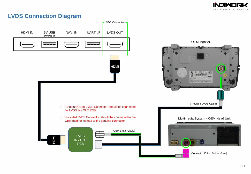
LVDS Connection Diagram
HDMI
HD
MI
Multimedia System - OEM Head Unit
HDMI IN 5V USBPOWER
NAVI IN UART I/F LVDS OUT
LVDS Connection
LVDS
IN / OUT
PCB
LCD
Cable(OEM LVDS Cable)
(Provided LVDS Cable)
13
OEM Monitor
(Connector Color: Pink or Gray)
• 'Genuine(OEM) LVDS Connector' should be connected
to ‘LVDS IN / OUT PCB'.
• ‘Provided LVDS Connector' should be connected to the
OEM monitor instead to the genuine connector.
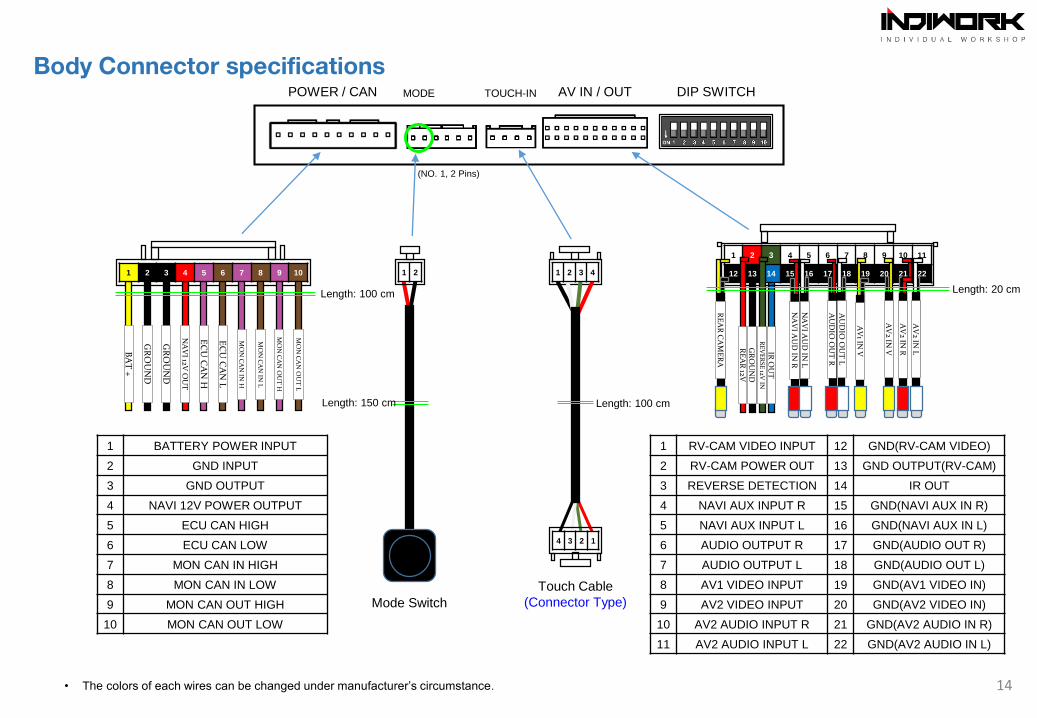
POWER / CAN MODE TOUCH-IN AV IN / OUT DIP SWITCH
1 2 3 4 5 6 7 8 9 10 11
12 13 14 15 16 17 18 19 20 21 22
1 BATTERY POWER INPUT
2 GND INPUT
3 GND OUTPUT
4 NAVI 12V POWER OUTPUT
5 ECU CAN HIGH
6 ECU CAN LOW
7 MON CAN IN HIGH
8 MON CAN IN LOW
9 MON CAN OUT HIGH
10 MON CAN OUT LOW
1 RV-CAM VIDEO INPUT 12 GND(RV-CAM VIDEO)
2 RV-CAM POWER OUT 13 GND OUTPUT(RV-CAM)
3 REVERSE DETECTION 14 IR OUT
4 NAVI AUX INPUT R 15 GND(NAVI AUX IN R)
5 NAVI AUX INPUT L 16 GND(NAVI AUX IN L)
6 AUDIO OUTPUT R 17 GND(AUDIO OUT R)
7 AUDIO OUTPUT L 18 GND(AUDIO OUT L)
8 AV1 VIDEO INPUT 19 GND(AV1 VIDEO IN)
9 AV2 VIDEO INPUT 20 GND(AV2 VIDEO IN)
10 AV2 AUDIO INPUT R 21 GND(AV2 AUDIO IN R)
11 AV2 AUDIO INPUT L 22 GND(AV2 AUDIO IN L)
GR
OU
ND
IR O
UT
RE
VE
RSE
12V IN
RE
AR
12V
RE
AR
CA
ME
RA
NA
VI A
UD
IN R
NA
VI A
UD
IN L
1 2 3 4
AU
DIO
OU
T R
AU
DIO
OU
T L
AV
1 IN V
AV
2 IN V
AV
2 IN R
AV
2 IN L
1 2
4 3 2 1
(NO. 1, 2 Pins)
Mode Switch
Touch Cable
(Connector Type)
Length: 100 cm Length: 20 cm
Length: 150 cm Length: 100 cm
• The colors of each wires can be changed under manufacturer’s circumstance. 14
Body Connector specifications
EC
U C
AN
H
EC
U C
AN
L
BA
T +
GR
OU
ND
GR
OU
ND
NA
VI 12V
OU
T
1 2 3 4 5 6 7 8 9 10
MO
N C
AN
IN H
MO
N C
AN
IN L
MO
N C
AN
OU
T H
MO
N C
AN
OU
T L
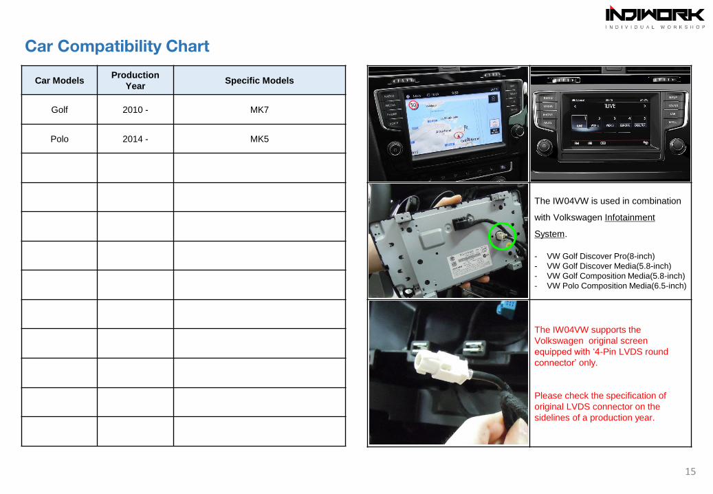
Car ModelsProduction
YearSpecific Models
Golf 2010 - MK7
Polo 2014 - MK5
The IW04VW is used in combination
with Volkswagen Infotainment
System.
- VW Golf Discover Pro(8-inch)
- VW Golf Discover Media(5.8-inch)
- VW Golf Composition Media(5.8-inch)
- VW Polo Composition Media(6.5-inch)
The IW03GF supports the
Chevrolet(GM) original screen &
Head unit equipped with ‘GVIF
connector’ only.
Please check the specification of
original GVIF connector on the
sidelines of a production year.
The IW04VW supports the
Volkswagen original screen
equipped with ‘4-Pin LVDS round
connector’ only.
Please check the specification of
original LVDS connector on the
sidelines of a production year.
15
Car Compatibility Chart
16
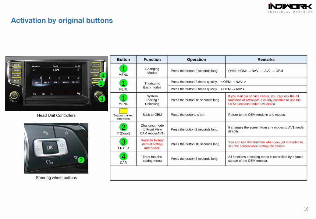
Steering wheel buttons
3
1
4
2
Activation by original buttons
Head Unit Controllers
1
Button Function Operation Remarks
MENU
Changing
ModesPress the button 2 seconds long. Order: HDMI → NAVI → AV2 → OEM
MENU
Shortcut to
Each modes
Press the button 2 times quickly. < OEM → NAVI >
Press the button 3 times quickly. < OEM → AV2 >
MENU
System
Locking /
Unlocking
Press the button 10 seconds long.
If you visit car service center, you can lock the all
functions of IW04VW. It is only possible to use the
OEM functions under it is locked.
Buttons marked
with yellow
Back to OEM Press the buttons short. Return to the OEM mode in any modes.
▽(Down)
Changing mode
to Front View
CAM mode(AV1)
Press the button 2 seconds long.It changes the screen from any modes to AV1 mode
directly.
ENTER
Reset to factory
default setting
and power.
Press the button 10 seconds long.You can use this function when you get in trouble to
see the screen while setting the screen.
CAR
Enter into the
setting menu Press the button 5 seconds long.
All functions of setting menu is controlled by a touch
screen of the OEM monitor.
1
1
3
2
4
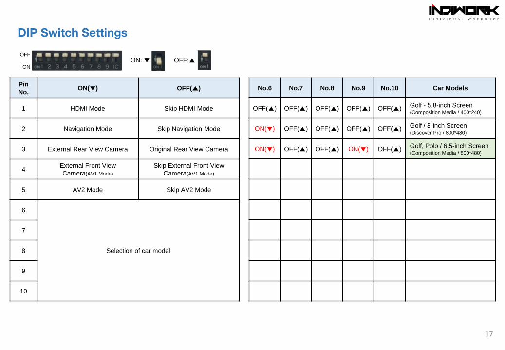
Pin
No.ON(▼) OFF(▲)
1 HDMI Mode Skip HDMI Mode
2 Navigation Mode Skip Navigation Mode
3 External Rear View Camera Original Rear View Camera
4External Front View
Camera(AV1 Mode)
Skip External Front View
Camera(AV1 Mode)
5 AV2 Mode Skip AV2 Mode
6
Selection of car model
7
8
9
10
17
OFF
ON
ON: ▼ OFF:▲
No.6 No.7 No.8 No.9 No.10 Car Models
OFF(▲) OFF(▲) OFF(▲) OFF(▲) OFF(▲)Golf - 5.8-inch Screen(Composition Media / 400*240)
ON(▼) OFF(▲) OFF(▲) OFF(▲) OFF(▲)Golf / 8-inch Screen(Discover Pro / 800*480)
ON(▼) OFF(▲) OFF(▲) ON(▼) OFF(▲)Golf, Polo / 6.5-inch Screen(Composition Media / 800*480)
DIP Switch Settings
18
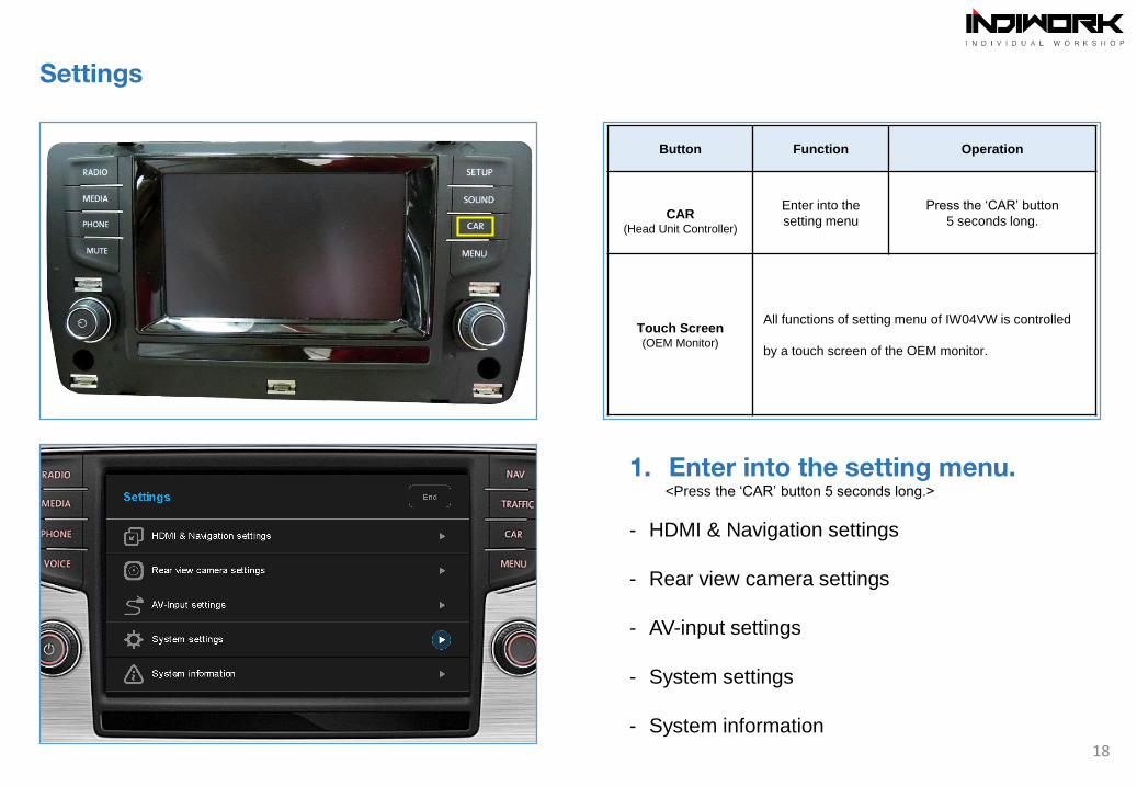
Button Function Operation
CAR(Head Unit Controller)
Enter into the
setting menu
Press the ‘CAR’ button
5 seconds long.
Touch Screen(OEM Monitor)
All functions of setting menu of IW04VW is controlled
by a touch screen of the OEM monitor.
Settings
1. Enter into the setting menu.
<Press the ‘CAR’ button 5 seconds long.>
- HDMI & Navigation settings
- Rear view camera settings
- AV-input settings
- System settings
- System information
19
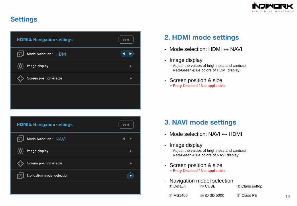
Settings
2. HDMI mode settings
- Mode selection: HDMI ↔ NAVI
- Image display= Adjust the values of brightness and contrast
Red-Green-Blue colors of HDMI display.
- Screen position & size= Entry Disabled / Not applicable.
3. NAVI mode settings
- Mode selection: NAVI ↔ HDMI
- Image display= Adjust the values of brightness and contrast
Red-Green-Blue colors of NAVI display.
- Screen position & size= Entry Disabled / Not applicable.
- Navigation model selection① Default ② CUBE ③ Class settop
④ MS1400 ⑤ iQ 3D 5000 ⑥ Class PE
20
Settings
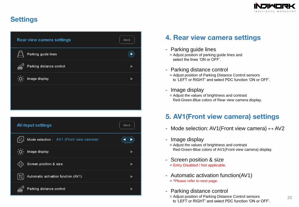
4. Rear view camera settings
- Parking guide lines= Adjust position of parking guide lines and
select the lines ‘ON or OFF’.
- Parking distance control= Adjust position of Parking Distance Control sensors
to ‘LEFT or RIGHT’ and select PDC function ‘ON or OFF’.
- Image display= Adjust the values of brightness and contrast
Red-Green-Blue colors of Rear view camera display.
5. AV1(Front view camera) settings
- Mode selection: AV1(Front view camera) ↔ AV2
- Image display= Adjust the values of brightness and contrast
Red-Green-Blue colors of AV1(Front view camera) display.
- Screen position & size= Entry Disabled / Not applicable.
- Automatic activation function(AV1)= *Please refer to next page.
- Parking distance control= Adjust position of Parking Distance Control sensors
to ‘LEFT or RIGHT’ and select PDC function ‘ON or OFF’.
21
Settings
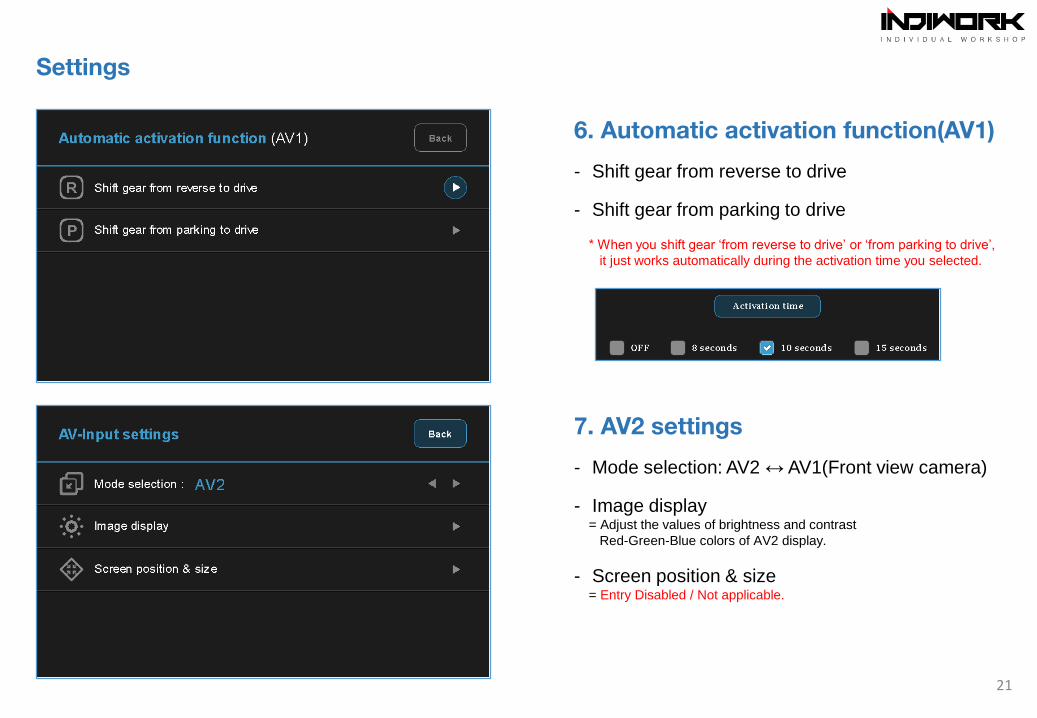
6. Automatic activation function(AV1)
- Shift gear from reverse to drive
- Shift gear from parking to drive
* When you shift gear ‘from reverse to drive’ or ‘from parking to drive’,
it just works automatically during the activation time you selected.
7. AV2 settings
- Mode selection: AV2 ↔ AV1(Front view camera)
- Image display= Adjust the values of brightness and contrast
Red-Green-Blue colors of AV2 display.
- Screen position & size= Entry Disabled / Not applicable.
22
Settings
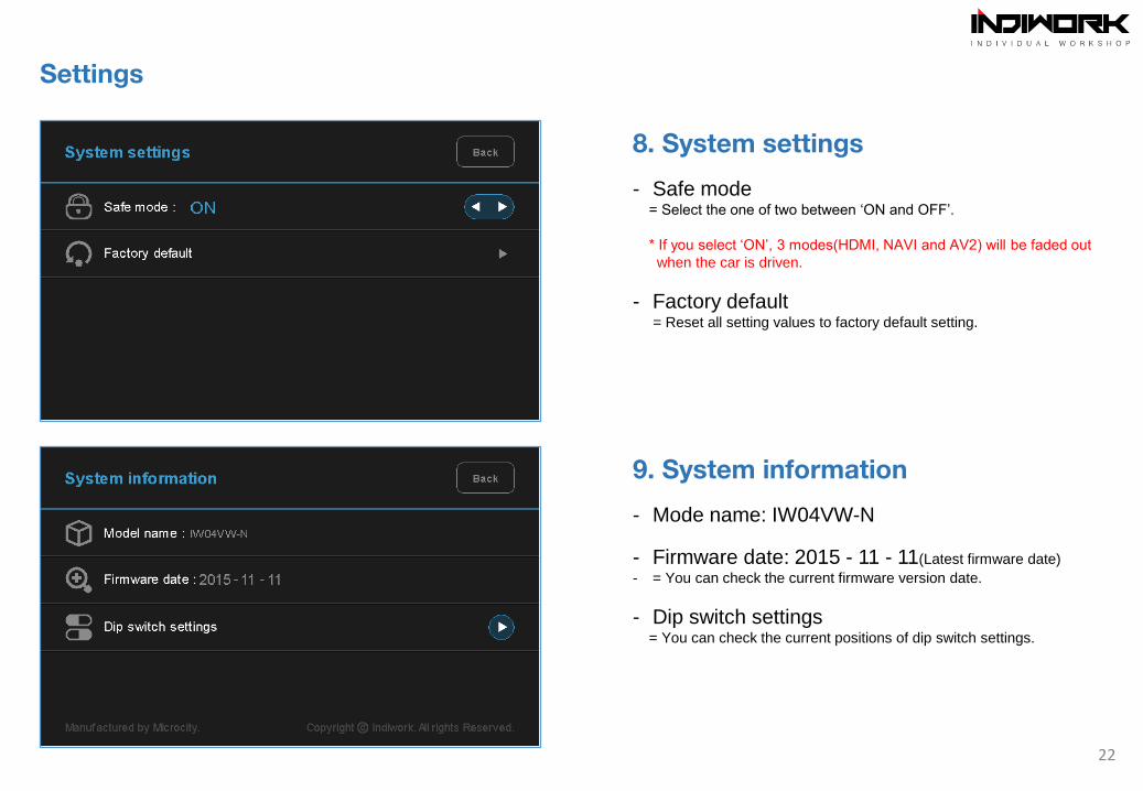
8. System settings
- Safe mode= Select the one of two between ‘ON and OFF’.
* If you select ‘ON’, 3 modes(HDMI, NAVI and AV2) will be faded out
when the car is driven.
- Factory default= Reset all setting values to factory default setting.
9. System information
- Mode name: IW04VW-N
- Firmware date: 2015 - 11 - 11(Latest firmware date)
- = You can check the current firmware version date.
- Dip switch settings= You can check the current positions of dip switch settings.

Copyright ⓒ indiwork. All Rights Reserved.

![DHL Just Sell Redesign Wireframes v0 - kleinrogge.co.uk file[Link] [Link] [Link] [Link] [Link] [Link] [Link] [Link] [Link] [Link] [Link] [Link] [Link] [Link] [Link] [Link] [Link] [Link]](https://img.pdfslide.us/doc/110x75/5e01cdbb8c84236e132280ba/dhl-just-sell-redesign-wireframes-v0-link-link-link-link-link-link.jpg)