Embed Size (px)
Citation preview
J Electr Eng Technol.2016; 11(?): 1921-718 http://dx.doi.org/10.5370/JEET.2016.11.1.1921
1921Copyright The Korean Institute of Electrical Engineers
This is an Open-Access article distributed under the terms of the Creative Commons Attribution Non-Commercial License (http://creativecommons.org/ licenses/by-nc/3.0/) which permits unrestricted non-commercial use, distribution, and reproduction in any medium, provided the original work is properly cited.
Capacitance Estimation Method of DC-Link Capacitors for BLDC Motor Drive Systems
Jong-Joo Moon*, Won-Sang Im**, June-Ho Park* and Jang-Mok Kim†
Abstract – This paper proposes a capacitance estimation method of the dc-link capacitor for brushless DC motor (BLDCM) drive systems. In order to estimate the dc-link capacitance, the BLDCM is operated in quadrant-II or -IV among four-quadrant operation. Quadrant-II and -IV are called reverse braking and forward braking, respectively. During the braking operation of the BLDCM, the capacitor is charged by the phase current and then the voltage is increased during the braking operation time. The capacitor current and voltage can be obtained by using the phase current sensor of BLDCM and the dc-link voltage sensor. The capacitance and be easily obtained by the voltage equation of the capacitor. The proposed method guarantees the reliable and simple calculation of the dc-link capacitance without additional hardware system except several the sensors already installed for the motor control system. The effectiveness of the proposed method is verified through both the simulation and experimental results.
Keywords: Capacitance estimation, Condition monitoring, BLDC motor drive system, Braking operation
1. Introduction BLDCM (Brushless DC motor) is becoming widely used
in various consumer and industrial drive systems [1-3]. In general, BLDCM drive system consists of a diode rectifier, dc-link capacitors, an inverter, phase current sensors, a dc-link voltage sensor, a control board and BLDCM as shown in Fig. 1.
Among components, the dc-link capacitor is one of the most essential parts to ensure the life time of the motor drive system. The dc-link capacitor is used to smooth the dc-link voltage, yet it is sensitive to temperature and the ripple frequency of the dc-link voltage. According to a failure survey, about 60~70% of power supply failures came from the capacitor breakdown [4-6]. Therefore, it is necessary to estimate the dc-link capacitance to maintain the motor drive system at normal condition. It will also improve the reliability and extend the durability of the total system [6-13].
Several researches proposed different methods to estimate the dc-link capacitance. One is the estimation of ESR (Equivalent Series Resistance) of the dc-link capacitor to decide whether it has a suitable value or not. Usually the ESR of the capacitor steadily increased when the performance of the capacitor deteriorates step by step [6-8]. The state averaging method, proposed by K. Harada,
derived a formula for ESR to be the ratio of the capacitor voltage to the capacitor current. The state averaging method is applied to a forward converter and a buck-boost converter [6]. K. A. proposed a real-time predictive-maintenance strategy for aluminum electrolytic capacitors used in uninterrupted power supplies [7]. This method detects the variations in the ESR and capacitance by using the capacitor current and voltage ripples. However, it requires a prior experimental test for proper operation. Y. M. Chen proposed a low-cost scheme to identify the increment of the ESR in real time [8]. However, this method requires an additional hardware to measure the capacitor voltage. The very small ESR value of MPPF capacitor makes the accurate estimation of ESR too difficult. Therefore, it is impossible to apply those method mentioned above to MPPF capacitor [6-8].
The other methods utilize the ac voltage injection [9, 10] or ac current injection [11-13] to the dc-link. A condition monitoring method [9] is proposed to estimates the ESR and the capacitance of the DC-link capacitor of the general drive system by applying short voltage pulses into a motor when the motor is stopped. However, it is difficult to measure the exact current for the estimation of the capacitor since the short voltage pulses cannot guarantee the settling time of the current, dead-time of the switching devices and the conversion time of the ADC (analog-to-digital converter). A. G. Abo-Khalil proposed the dc-link capacitance estimation method for the AC/DC/AC PWM converters using the ac-voltage injection [10]. The injected ac-voltage causes a ripple-voltage on the dc-link. The capacitance can be estimated by using the variation of the capacitor voltage and the dc-current. D.-C. Lee proposed
† Corresponding Author: Dept. of Electrical Engineering, Pusan National University, Korea. ([email protected])
* Dept. of Electrical Engineering, Pusan National University, Korea. ([email protected])
** Dept. of Electrical and Computer Engineering, Lehigh University, Bethlehem, PA, USA. ([email protected])
Received: June 26, 2015; Accepted: November 29, 2015
ISSN(Print) 1975-0102ISSN(Online) 2093-7423
Capacitance Estimation Method of DC-Link Capacitors for BLDC Motor Drive Systems
710 J Electr Eng Technol.2016; 11(1): 709-718
online capacitance estimation of DC-link electrolytic capacitors for three-phase AC/DC/AC PWM converters [11]. In this method, a regulated ac-current component is injected into the q-axis input current component of the AC/DC PWM converter. X.-S. Pu estimates the ESR of the dc-link capacitor by using ac-current injection [12]. Although the author considers the effect of temperature on the resistance, the implementation is similar with [11]. The method proposed by T. H. Nguyen uses the regenerative operation of the PMSM for the estimation of the dc-link capacitor [13]. In the regenerative mode, the ac-current is injected to the q-axis current. The implementation for the estimation of the capacitance is similar with [11-12]. However, those methods [10-13] are complicated to implement the estimation operation due to the double sampling on the on/off sequences of the PWM, band pass filter, and the settling time of the dc-current. In addition, the reliability of such a monitoring system depends on the accuracy of the sensors, the proper ground wiring layout, and the shielding, which removes noise interference. Moreover, the accuracy of the estimated capacitance value depends on the adjustable gain of the recursive least square (RLS) method because this gain must be obtained by a trial and error method.
In this paper, the proposed method only uses the phase currents and the dc-link voltage during the braking operation of the BLDCM without any additional hardware except the sensors used in the motor drive system. Unlike the conventional methods, the proposed method can be easily implemented without the double sampling method, trial and error method, or any filter algorithm. A reliable result can be obtained by applying this method to normal BLDC motor drive system. The usefulness of the proposed method is verified through the computer simulation and the experimental results.
2. Control of Brushless DC Motor Fig. 1 shows a typical BLDC motor drive system. It
consists of a diode rectifier, dc-link capacitor, a PWM inverter, dc-link voltage sensor, phase current sensors, BLDCM and hall sensor. The operation of the BLDCM drive system can be divided into motoring and the braking operations. The proposed method of the capacitor estimation is activated only during the braking operation.
Fig. 1. BLDC motor drive system
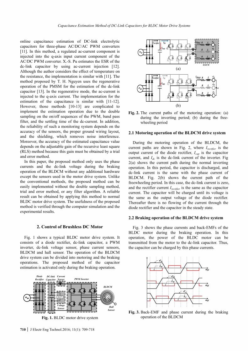
2.1 Motoring operation of the BLDCM drive system During the motoring operation of the BLDCM, the
current paths are shown in Fig. 2, where Irectifier is the output current of the diode rectifier, Icap is the capacitor current, and Idc is the dc-link current of the inverter. Fig 2(a) shows the current path during the normal inverting operation. In this period, the capacitor is discharged, and dc-link current is the same with the phase current of BLDCM. Fig. 2(b) shows the current path of the freewheeling period. In this case, the dc-link current is zero, and the rectifier current Irectifier is the same as the capacitor current. The capacitor will be charged until its voltage is the same as the output voltage of the diode rectifier. Thereafter there is no flowing of the current through the diode rectifier and the capacitor in the steady state.
2.2 Braking operation of the BLDCM drive system
Fig. 3 shows the phase currents and back-EMFs of the
BLDC motor during the braking operation. In this operation, the power of the BLDC motor can be transmitted from the motor to the dc-link capacitor. Thus, the capacitor can be charged by this phase currents.
Fig. 3. Back-EMF and phase current during the braking
operation of the BLDCM
(a)
(b)
Fig. 2. The current paths of the motoring operation: (a) during the inverting period; (b) during the free-wheeling period

Jong-Joo Moon, Won-Sang Im, June-Ho Park and Jang-Mok Kim
http://www.jeet.or.kr 711
Fig. 4 and 5 show the current paths of the braking operation during the freewheeling and the regenerating periods, respectively.
In the freewheeling period, D1 and S5 are conducting as shown in Fig. 4(a). The voltage equation can be described by (1).
( )
0 ( ) 2 2 ( )ss s s s
di tR i t L e t
dt= +- - (1)
where, is(t), es(t), Rs and Ls denote the phase current, the phase back-EMF, the phase resistor and the phase inductance, respectively. In this period, the rectifier and the capacitor currents are zero, while the phase current is freewheeling as shown in Fig. 4 (a). This means that the dc-link capacitor cannot be estimated in this case.
When S2 is turned OFF, freewheeling diodes D1 and D2 are conducting as shown in Fig. 5(a). During this inverting period, the voltage equation is described by
( )
2 ( ) 2 2 ( )sdc s s s s
di tV R i t L e t
dt= +- - . (2)
Because the rectifier diodes are blocking the negative
current of the rectifier diode, the rectifier current (Irectifier) is always zero. Thus, the inverse dc current only flows through the dc-link capacitor as shown in Fig. 5 (a). Fig. 5 (b) shows the dc-link and the capacitor currents during the regenerative operation. In this period, the capacitor voltage can be increased by the capacitor current. The capacitor current can be easily obtained from the phase current because these two currents are the same as shown in Fig. 5(b).
Irectifier
S3 S5
S4 S6 S2
D1Icap
Idc Iphase L
L
L
R
R
R
n
ea
eb
ec
(a)
(b)
Fig. 4. (a) Current paths of the freewheeling period during the braking operation; (b) Dc-link, capacitor and phase currents
Irectifier
S3 S5
S4 S6 D2
D1Icap
IdcIphase L
L
L
R
R
R
n
ea
eb
ec
(a)
(b)
Fig. 5. (a) The current paths of the regenerating period during the braking operation; (b) Dc-link, capacitor and phase currents on the time domain
3. Proposed Capacitance Estimation Method
3.1 Algorithm for the proposed method
The main concept of the proposed capacitance
estimation method is to use the variation of the capacitor voltage and the mean value of the capacitor current during the braking operation of the BLDCM.
Fig. 6 shows the capacitor voltage and the capacitor current during the braking operation. The capacitor voltage is increasing, and proportional to the charging capacitor current. The capacitor current can be obtained through the phase current sensors because the phase current is the same as the capacitor current during the braking operation as mentioned before.
Fig. 6. Dc-link voltage and the capacitor current during the
braking operation
Capacitance Estimation Method of DC-Link Capacitors for BLDC Motor Drive Systems
712 J Electr Eng Technol.2016; 11(1): 709-718
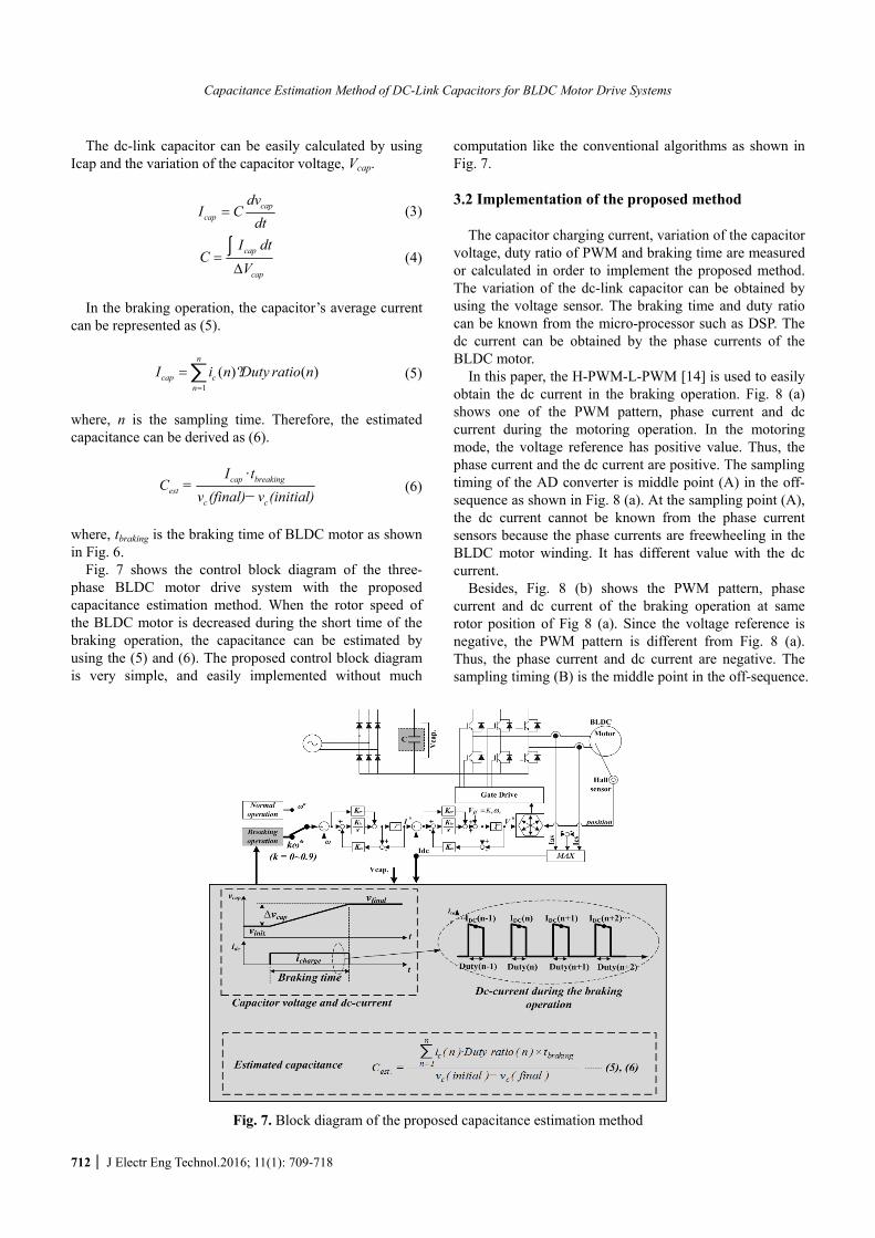
The dc-link capacitor can be easily calculated by using Icap and the variation of the capacitor voltage, Vcap.
capcap
dvI C
dt= (3)
cap
cap
I dtC
V=
Δ∫ (4)
In the braking operation, the capacitor’s average current
can be represented as (5).
1
( )? ( )n
cap cn
I i n Duty ratio n=
=∑ (5)
where, n is the sampling time. Therefore, the estimated capacitance can be derived as (6).
·cap breaking
estc c
I tC =
v (final) v (initial)- (6)
where, tbraking is the braking time of BLDC motor as shown in Fig. 6.
Fig. 7 shows the control block diagram of the three-phase BLDC motor drive system with the proposed capacitance estimation method. When the rotor speed of the BLDC motor is decreased during the short time of the braking operation, the capacitance can be estimated by using the (5) and (6). The proposed control block diagram is very simple, and easily implemented without much
computation like the conventional algorithms as shown in Fig. 7.
3.2 Implementation of the proposed method
The capacitor charging current, variation of the capacitor
voltage, duty ratio of PWM and braking time are measured or calculated in order to implement the proposed method. The variation of the dc-link capacitor can be obtained by using the voltage sensor. The braking time and duty ratio can be known from the micro-processor such as DSP. The dc current can be obtained by the phase currents of the BLDC motor.
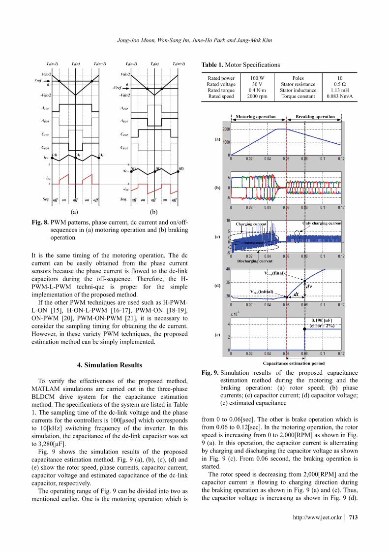
In this paper, the H-PWM-L-PWM [14] is used to easily obtain the dc current in the braking operation. Fig. 8 (a) shows one of the PWM pattern, phase current and dc current during the motoring operation. In the motoring mode, the voltage reference has positive value. Thus, the phase current and the dc current are positive. The sampling timing of the AD converter is middle point (A) in the off-sequence as shown in Fig. 8 (a). At the sampling point (A), the dc current cannot be known from the phase current sensors because the phase currents are freewheeling in the BLDC motor winding. It has different value with the dc current.
Besides, Fig. 8 (b) shows the PWM pattern, phase current and dc current of the braking operation at same rotor position of Fig 8 (a). Since the voltage reference is negative, the PWM pattern is different from Fig. 8 (a). Thus, the phase current and dc current are negative. The sampling timing (B) is the middle point in the off-sequence.
Fig. 7. Block diagram of the proposed capacitance estimation method
Jong-Joo Moon, Won-Sang Im, June-Ho Park and Jang-Mok Kim
http://www.jeet.or.kr 713
It is the same timing of the motoring operation. The dc current can be easily obtained from the phase current sensors because the phase current is flowed to the dc-link capacitors during the off-sequence. Therefore, the H-PWM-L-PWM techni-que is proper for the simple implementation of the proposed method.
If the other PWM techniques are used such as H-PWM-L-ON [15], H-ON-L-PWM [16-17], PWM-ON [18-19], ON-PWM [20], PWM-ON-PWM [21], it is necessary to consider the sampling timing for obtaining the dc current. However, in these variety PWM techniques, the proposed estimation method can be simply implemented.
4. Simulation Results To verify the effectiveness of the proposed method,
MATLAM simulations are carried out in the three-phase BLDCM drive system for the capacitance estimation method. The specifications of the system are listed in Table 1. The sampling time of the dc-link voltage and the phase currents for the controllers is 100[μsec] which corresponds to 10[kHz] switching frequency of the inverter. In this simulation, the capacitance of the dc-link capacitor was set to 3,280[μF].
Fig. 9 shows the simulation results of the proposed capacitance estimation method. Fig. 9 (a), (b), (c), (d) and (e) show the rotor speed, phase currents, capacitor current, capacitor voltage and estimated capacitance of the dc-link capacitor, respectively.
The operating range of Fig. 9 can be divided into two as mentioned earlier. One is the motoring operation which is
from 0 to 0.06[sec]. The other is brake operation which is from 0.06 to 0.12[sec]. In the motoring operation, the rotor speed is increasing from 0 to 2,000[RPM] as shown in Fig. 9 (a). In this operation, the capacitor current is alternating by charging and discharging the capacitor voltage as shown in Fig. 9 (c). From 0.06 second, the braking operation is started.
The rotor speed is decreasing from 2,000[RPM] and the capacitor current is flowing to charging direction during the braking operation as shown in Fig. 9 (a) and (c). Thus, the capacitor voltage is increasing as shown in Fig. 9 (d).
(a) (b) Fig. 8. PWM patterns, phase current, dc current and on/off-
sequences in (a) motoring operation and (b) braking operation
Table 1. Motor Specifications
Rated power Rated voltageRated torque Rated speed
100 W 30 V
0.4 N·m 2000 rpm
Poles Stator resistance Stator inductance Torque constant
10 0.5 Ω
1.13 mH 0.083 Nm/A
Fig. 9. Simulation results of the proposed capacitance
estimation method during the motoring and the braking operation: (a) rotor speed; (b) phase currents; (c) capacitor current; (d) capacitor voltage; (e) estimated capacitance
Capacitance Estimation Method of DC-Link Capacitors for BLDC Motor Drive Systems
714 J Electr Eng Technol.2016; 11(1): 709-718
Therefore, the capacitance can be estimated by using the variation of the capacitor voltage and the capacitor current from t=0.06 to 0.08[sec] during the braking operation. It is calculated at 0.08[sec] as shown in Fig. 9 (e).
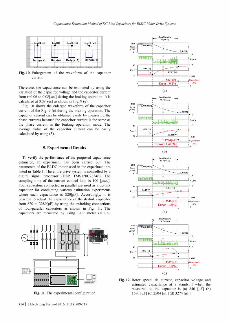
Fig. 10 shows the enlarged waveform of the capacitor current of the Fig. 9 (c) during the braking operation. The capacitor current can be obtained easily by measuring the phase currents because the capacitor current is the same as the phase current in the braking operation mode. The average value of the capacitor current can be easily calculated by using (5).
5. Experimental Results To verify the performance of the proposed capacitance
estimator, an experiment has been carried out. The parameters of the BLDC motor used in the experiment are listed in Table 1. The entire drive system is controlled by a digital signal processor (DSP, TMS320C28346). The sampling time of the current control loop is 100 [μsec]. Four capacitors connected in parallel are used as a dc-link capacitor for conducting various estimation experiments where each capacitance is 820[μF]. Accordingly, it is possible to adjust the capacitance of the dc-link capacitor from 820 to 3280[μF] by using the switching connections of four-parallel capacitors as shown in Fig. 11. The capacitors are measured by using LCR meter (HIOKI
Fig. 10. Enlargement of the waveform of the capacitor
current
(a)
(b)
(c)
(d)
Fig. 12. Rotor speed, dc current, capacitor voltage and estimated capacitance at a standstill when the measured dc-link capacitor is (a) 840 [μF] (b) 1680 [μF] (c) 2504 [μF] (d) 3274 [μF] Fig. 11. The experimental configuration
Jong-Joo Moon, Won-Sang Im, June-Ho Park and Jang-Mok Kim
http://www.jeet.or.kr 715
3532) for the comparison between the estimated value and the measured value. The measured values are 840, 1680, 2504, and 3274 [μF] in the four cases.
Fig. 12 shows the estimated results obtained from the proposed method. The BLDC motor speed is sopped from 2,000 [RPM] by the braking operation. During this braking time, the capacitor voltage is increased because the capacitor current flow into the capacitor as shown in Fig. 12. The capacitor’s average current can be obtained by using (5), and the capacitance can be calculated by using (6). As shown from Fig. 12, the value of the estimated capacitance is nearly identical to the real capacitance.
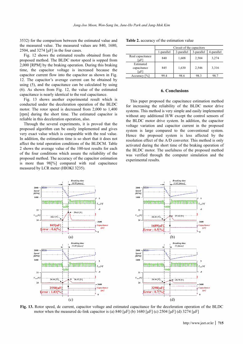
Fig. 13 shows another experimental result which is conducted under the deceleration operation of the BLDC motor. The rotor speed is decreased from 2,000 to 1,400 [rpm] during the short time. The estimated capacitor is reliable in this deceleration operation, also.
Through the several experiments, it is proved that the proposed algorithm can be easily implemented and gives very exact value which is comparable with the real value. In addition, the estimation time is so short that it does not affect the total operation conditions of the BLDCM. Table 2 shows the average value of the 100-test results for each of the four conditions which assure the reliability of the proposed method. The accuracy of the capacitor estimation is more than 98[%] compared with real capacitance measured by LCR meter (HIOKI 3235).
Table 2. accuracy of the estimation value
Circuit of the capacitors 1-parallel 2-parallel 3-parallel 4-parallel
Real capacitance [μF] 840 1,608 2,504 3,274
Estimated capacitance
[μF] 845 1,630 2,546 3,316
Accuracy [%] 99.4 98.6 98.3 98.7
6. Conclusions This paper proposed the capacitance estimation method
for increasing the reliability of the BLDC motor drive systems. This method is very simple and easily implemented without any additional H/W except the control sensors of the BLDC motor drive system. In addition, the capacitor voltage variation and capacitor current in the proposed system is large compared to the conventional system. Hence the proposed system is less affected by the resolution effect of the A/D converter. This method is only activated during the short time of the braking operation of the BLDC motor. The usefulness of the proposed method was verified through the computer simulation and the experimental results.
(a)
(b)
(c)
(d)
Fig. 13. Rotor speed, dc current, capacitor voltage and estimated capacitance for the deceleration operation of the BLDC motor when the measured dc-link capacitor is (a) 840 [μF] (b) 1680 [μF] (c) 2504 [μF] (d) 3274 [μF]

Capacitance Estimation Method of DC-Link Capacitors for BLDC Motor Drive Systems
716 J Electr Eng Technol.2016; 11(1): 709-718
Acknowledgements This work was supported by the Human Resources
Program in Energy Technology of Korea Institute of Energy Technology Evaluation and Planning (KETEP), granted financial resource from the Ministry of Trade, Industry & Energy, Republic of Korea. (No. 2015 4030200670)
References
[1] N. H. Kim, O. Yang, and M. H. Kim, “BLDC motor control algorithm for industrial applications using a general purpose processor,” Journal of Power Electronics, vol. 7, no. 2, pp. 132-139, Apr. 2007.
[2] W. S. Im, J. P. Kim, J. M. Kim K. R. Baek, “Torque Maximization Control of 3-Phase BLDC Motors in the High Speed Region,” Journal of Power Electro-nics, vol. 10, no. 6, pp. 717-723, Jun. 2010.
[3] H. W. Kim, H. K. Shin, H. S. Mok, Y. K. Lee, K. Y. Cho, “Novel PWM Method with Low Ripple Current for Position Control Applications of BLDC motors,” Journal of Power Electronics, vol. 11, no. 5, pp. 726-733, Sept. 2011.
[4] A. Layhani, P. Venet, G. Grellet, and P. J. Viverge, “Failure prediction of electrolytic capacitors during operation of a switch mode power supply,” IEEE Trans. Power Electron., vol. 13, no. 6, pp. 1199-1207, Nov. 1998.
[5] C. Wang, T. C. Cheng, G. Zheng, Y. D, L. Mu, B. Palk and M. Moon, “Failure Analysis of Composite Dielectric of Power Capacitors in Distribution Systems,” IEEE Transactions Dielectrics and Elec-trical Insulation, Vol. 5, No. 4, pp.583-58, Aug. 1998.
[6] K. Harada, A. Katsuki, and M. Fujiwara, “Use of ESR for deterioration diagnosis of electrolytic capacitor,” IEEE Trans. Power Electron.,vol. 8, no. 4, pp. 355-361, Oct. 1993
[7] K. Abdennadher, P. Venet, F. Rojat, J. M. Retif, and C. Rosset, “A real-time predictive-maintenance system for aluminum electrolytic capacitors used in uninterru-pted power supplied,” IEEE Trans. Ind. Appl., vol. 46, no. 4, pp. 1644-1652, Jul./Aug. 2010.
[8] Y. M. Chen, H. C. Wu, M. W. Chou, and K. Y. Lee, “Online failure prediction of the electrolytic capacitor for LC filter of switching-mode power converters,” IEEE Trans. Ind. Electron., vol. 55, no. 1, pp. 400-406, Jan. 2008.
[9] K. W. Lee, M. C. Kim, J. H. Yoon, and S. B. Lee, J. Y. Yoo, “Condition Monitoring of DC-Link Electrolytic Capacitors in Adjustable-Speed Drives”, IEEE Trans. Industry Applications, vol. 44, no. 5, pp. 1606-1613, Sept/Oct. 2008.
[10] A. G. Abo-Khalil, and D. C. Lee, “DC-Link Capacit-ance Estimation in AC/DC/ACPWM Converters
Using Voltage Injection”, IEEE Trans. Industry Applications, vol. 44, no. 5, pp. 1631-1637, Sept/Oct. 2008.
[11] D. C. Lee, K. J. Lee, J. K. Seok, and J. W. Choi, “Online capacitance estimation of DC-link elec-trolytic capacitors for three-phase AC/DC/AC PWM converters using recursive least squares method”, IEEE Trans. Electric Power Applications, vol. 152, no. 6, pp. 1503-1508, Nov. 2005.
[12] X. S. Pu, T. H. Nguyen, D. C. Lee, K. B. Lee and J. M. Kim, “Fault Diagnosis of DC-Link Capacitors in Three-Phase AC/DC PWM Converters by Online Estimation of Equivalent Series Resistance”, IEEE Trans. Industrial Electronics, early access articles, 2012.
[13] T. H. Nguyen, and D. C. Lee, “Deterioration Moni-toring of DC-Link Capacitors in AC Machine Drives by Current Induction”, IEEE Trans. Power Electronics, vol. 30, no. 3, pp. 1126-1130, Mar. 2015.
[14] Q. Li, H. Huang, and B. Yin, “The study of PWM methods in permanent magnet brushless DC motor speed control system,” in Proc. Int. Conf. Electr. Mach. Syst., Oct. 2008, pp. 3897–3900.
[15] G. J. Su and J. W. McKeever, “Low-cost sensorless control of brushless DC motors with improved speed range,” IEEE Trans. Power Electron., vol. 19, no. 2, pp. 296-302, Mar. 2004.
[16] R. C. Becerra, T. M. Jahns, and M. Ehsani, “Four-quadrant sensorless brushless ECM drive,” in Proc. IEEE Appl. Power Electron. Conf., Mar. 1991, pp. 202–209.
[17] J. Shao, D. Nolan, M. Teissier, and D. Swanson, “A novel microcontroller based sensorless brushless DC (BLDC) motor drive for automotive fuel pumps,” in Proc. IEEE Trans. Ind. Appl., Dec. 2003, vol. 39, pp. 1734-1740.
[18] Y. S. Lai, F. S. Shyu, and Y. H. Chang, “Novel loss reduction pulse-width modulation technique for brushless DC motor drives fed by MOSFET inverter,” IEEE Trans. Power Electron., vol. 19, no. 6, pp. 1646-1656, Nov. 2004.
[19] Y. S. Lai, F. S. Shyu, and Y. H. Chang, “Novel pulse-width modulation technique with loss reduction for small power brushless DCmotor drives,” in Proc. Conf. Rec. IEEE IAS Ann. Meet., 2002, pp. 2057–2064.
[20] Tokyo Shibaura Electric Co., “Drive control apparatus for brushless DC motor and driving method therefore,” U.S. Patent 5491393, 1996.
[21] J. Fang, H. Li, and B. Han, “Torque ripple reduction in BLDC torque motor with nonideal back EMF,” IEEE Trans. Power Electron., vol. 27, no. 11, pp. 4630-4637, Nov. 2012.
Jong-Joo Moon, Won-Sang Im, June-Ho Park and Jang-Mok Kim
http://www.jeet.or.kr 717
Jong-Joo Moon He received the B.S. degree from the Department of Elec-tronics Engineering, Inje University, Kimhea, Korea, in 2008 and the M.S. degree from the Department of Electrical Engineering, Pusan National University, Busan, Korea, in 2011 where he is currently working toward
the Ph.D. degree. His research interests are electric machine drives, multi-phase motor drives, fault diagnosis and tolerance control.
Won-Sang Im He received B.S., M.S., Ph.D. degrees in electrical engineering from Pusan National University, Busan, Korea. He is currently a Postdoctoral Researcher at Lehigh University, PA, USA. His research interests are electric machine drives, fault diagnosis and tolerance control.
June-Ho Park He received the B.S., M.S. and Ph.D. degrees from Seoul National University, Seoul, Korea in 1978, 1980, and 1987, respectively, all in electrical engineering. He is cur-rently a Professor at the School of Electrical Engineering, Pusan National University, Busan, Korea. His research
interests include intelligent systems applications to power systems. Dr. Park has been a member of the IEEE Power Engineering Society.
Jang-Mok Kim He received the B.S. degree from Pusan National University (PNU), Busan, Korea, in 1988 and the M.S. and Ph.D. degrees from the Department of Electrical Engineering, Seoul National University, Seoul, Korea, in 1991 and 1996, respectively. From 1997 to 2000, he was a Senior
Research Engineer with the Korea Electrical Power Research Institute. Since 2001, he has been with the School of Electrical Engineering, PNU, where he is currently a Research Member with the Research Institute of Com-puters, Information and Communication, a Faculty Member, and the Head of the LG Electronics Smart Control Center. As a Visiting Scholar, he was with the Center for Advanced Power Systems, Florida State University, Tallahassee, FL, USA, in 2007. His current interests include control of electric machines, electric vehicle propulsion, and power quality.