Embed Size (px)
Citation preview

INSTRUCTION MANUALFOR
OVERCURRENT RELAYSBE1-50/51B-214 AND BE1-50/51B-225
Publication: 9 2520 00 994Revision: G 03/2001

BE1-50/51B-214/-225 - Introduction i
W A R N I N G !To avoid personal injury or equipment damage, only qualifiedpersonnel should perform the procedures presented in this manual.
INTRODUCTION
This manual provides information concerning the operation and installation of the BE1-50/51B-214 and BE1-50/51B-225 Overcurrent Relays. To accomplish this, the following is provided.
� Specifications
� Functional description
� Mounting information
� Setting procedure/example

ii BE1-50/51B-214/-225 - Introduction
CONFIDENTIAL INFORMATION
OF BASLER ELECTRIC COMPANY, HIGHLAND, IL. IT IS LOANED FORCONFIDENTIAL USE, SUBJECT TO RETURN ON REQUEST, AND WITH THE MUTUALUNDERSTANDING THAT IT WILL NOT BE USED IN ANY MANNER DETRIMENTAL TOTHE INTEREST OF BASLER ELECTRIC COMPANY.
First Printing: July 1995
Printed in USA
© 1995 - 2001 Basler Electric Co., Highland, IL 62249
March 2001
It is not the intention of this manual to cover all details and variations in equipment, nor does thismanual provide data for every possible contingency regarding installation or operation. Theavailability and design of all features and options are subject to modification without notice.Should further information be required, contact Basler Electric Company, Highland, Illinois.
BASLER ELECTRICROUTE 143, BOX 269
HIGHLAND, IL 62249 USAhttp://www.basler.com, [email protected]
PHONE 618-654-2341 FAX 618-654-2351

BE1-50/51B-214/-225 - Introduction iii
��������
SECTION 1 GENERAL INFORMATION . . . . . . . . . . . . . . . . . . . . . . . 1-1
Description . . . . . . . . . . . . . . . . . . . . . . . . . . . . . . . . . . . . . . . . . . . . . . . . . . . . . . . . 1-1Application . . . . . . . . . . . . . . . . . . . . . . . . . . . . . . . . . . . . . . . . . . . . . . . . . . . . . . . . 1-1Features . . . . . . . . . . . . . . . . . . . . . . . . . . . . . . . . . . . . . . . . . . . . . . . . . . . . . . . . 1-2Advantages . . . . . . . . . . . . . . . . . . . . . . . . . . . . . . . . . . . . . . . . . . . . . . . . . . . . . . . . 1-2Specifications . . . . . . . . . . . . . . . . . . . . . . . . . . . . . . . . . . . . . . . . . . . . . . . . . . . . . . . . 1-2Characteristic Curves . . . . . . . . . . . . . . . . . . . . . . . . . . . . . . . . . . . . . . . . . . . . . . . . . 1-10
SECTION 2 HUMAN MACHINE INTERFACE . . . . . . . . . . . . . . . . . . . 2-1
SECTION 3 FUNCTIONAL DESCRIPTION . . . . . . . . . . . . . . . . . . . . . 3-1
General . . . . . . . . . . . . . . . . . . . . . . . . . . . . . . . . . . . . . . . . . . . . . . . . . . . . . . . . 3-1Functional Description . . . . . . . . . . . . . . . . . . . . . . . . . . . . . . . . . . . . . . . . . . . . . . . . . 3-1
Sensing Input . . . . . . . . . . . . . . . . . . . . . . . . . . . . . . . . . . . . . . . . . . . . . . . . . . . . . 3-1Power Supply . . . . . . . . . . . . . . . . . . . . . . . . . . . . . . . . . . . . . . . . . . . . . . . . . . . . . 3-1Instantaneous Signal . . . . . . . . . . . . . . . . . . . . . . . . . . . . . . . . . . . . . . . . . . . . . . . 3-1Time Signal . . . . . . . . . . . . . . . . . . . . . . . . . . . . . . . . . . . . . . . . . . . . . . . . . . . . . . . 3-1Microprocessor . . . . . . . . . . . . . . . . . . . . . . . . . . . . . . . . . . . . . . . . . . . . . . . . . . . . 3-1Power-Off Sensing . . . . . . . . . . . . . . . . . . . . . . . . . . . . . . . . . . . . . . . . . . . . . . . . . 3-1Outputs . . . . . . . . . . . . . . . . . . . . . . . . . . . . . . . . . . . . . . . . . . . . . . . . . . . . . . . . 3-2
SECTION 4 INSTALLATION . . . . . . . . . . . . . . . . . . . . . . . . . . . . . . . . 4-1
General . . . . . . . . . . . . . . . . . . . . . . . . . . . . . . . . . . . . . . . . . . . . . . . . . . . . . . . . 4-1Dielectric Test . . . . . . . . . . . . . . . . . . . . . . . . . . . . . . . . . . . . . . . . . . . . . . . . . . . . . . . . 4-1Mounting . . . . . . . . . . . . . . . . . . . . . . . . . . . . . . . . . . . . . . . . . . . . . . . . . . . . . . . . 4-1Factory Settings . . . . . . . . . . . . . . . . . . . . . . . . . . . . . . . . . . . . . . . . . . . . . . . . . . . . . . 4-1Installation . . . . . . . . . . . . . . . . . . . . . . . . . . . . . . . . . . . . . . . . . . . . . . . . . . . . . . . . 4-1Application Coordination . . . . . . . . . . . . . . . . . . . . . . . . . . . . . . . . . . . . . . . . . . . . . . . . 4-2Connections . . . . . . . . . . . . . . . . . . . . . . . . . . . . . . . . . . . . . . . . . . . . . . . . . . . . . . . . 4-3
AC Input Connections . . . . . . . . . . . . . . . . . . . . . . . . . . . . . . . . . . . . . . . . . . . . . . 4-3DC Control Connections . . . . . . . . . . . . . . . . . . . . . . . . . . . . . . . . . . . . . . . . . . . . 4-4
SECTION 5 TESTING . . . . . . . . . . . . . . . . . . . . . . . . . . . . . . . . . . . . . . 5-1
General . . . . . . . . . . . . . . . . . . . . . . . . . . . . . . . . . . . . . . . . . . . . . . . . . . . . . . . . 5-1Dielectric Test . . . . . . . . . . . . . . . . . . . . . . . . . . . . . . . . . . . . . . . . . . . . . . . . . . . . . . . . 5-1Operational Test Procedure . . . . . . . . . . . . . . . . . . . . . . . . . . . . . . . . . . . . . . . . . . . . . 5-1
Test Equipment Required . . . . . . . . . . . . . . . . . . . . . . . . . . . . . . . . . . . . . . . . . . . 5-1Pickup and Timing Test Setup . . . . . . . . . . . . . . . . . . . . . . . . . . . . . . . . . . . . . . . . 5-2Target Operational Test Setup . . . . . . . . . . . . . . . . . . . . . . . . . . . . . . . . . . . . . . . . 5-2Test Procedure, Models BE1-50/51B-214 (Five Ampere Sensing Input) . . . . . . . 5-3Test Procedure, Models BE1-50/51B-225 (One Ampere Sensing Input) . . . . . . . 5-5
Setting the Relay . . . . . . . . . . . . . . . . . . . . . . . . . . . . . . . . . . . . . . . . . . . . . . . . . . . . . . 5-8Periodic Tests . . . . . . . . . . . . . . . . . . . . . . . . . . . . . . . . . . . . . . . . . . . . . . . . . . . . . . . . 5-8
General . . . . . . . . . . . . . . . . . . . . . . . . . . . . . . . . . . . . . . . . . . . . . . . . . . . . . . . . . . 5-8Periodic Test . . . . . . . . . . . . . . . . . . . . . . . . . . . . . . . . . . . . . . . . . . . . . . . . . . . . . . 5-8
iv BE1-50/51B-214/-225 - Introduction
CONTENTS - Continued
SECTION 6 MAINTENANCE . . . . . . . . . . . . . . . . . . . . . . . . . . . . . 6-1
General . . . . . . . . . . . . . . . . . . . . . . . . . . . . . . . . . . . . . . . . . . . . . . . . . . . . . . . . . . . . . 6-1In-House Repair . . . . . . . . . . . . . . . . . . . . . . . . . . . . . . . . . . . . . . . . . . . . . . . . . . . . . . 6-1Storage . . . . . . . . . . . . . . . . . . . . . . . . . . . . . . . . . . . . . . . . . . . . . . . . . . . . . . . . . . . . . 6-1Periodic Tests . . . . . . . . . . . . . . . . . . . . . . . . . . . . . . . . . . . . . . . . . . . . . . . . . . . . . . . . 6-1
General . . . . . . . . . . . . . . . . . . . . . . . . . . . . . . . . . . . . . . . . . . . . . . . . . . . . . . . . . . 6-1Periodic Test . . . . . . . . . . . . . . . . . . . . . . . . . . . . . . . . . . . . . . . . . . . . . . . . . . . . . . 6-1
SECTION 7 MANUAL CHANGE INFORMATION . . . . . . . . . . . . . 7-1

BE1-50/51B-214/-225 - General Information 1-1
SECTION 1 • GENERAL INFORMATION
DESCRIPTION
BE1-50/51B-214 and BE1-50/51B-225 Overcurrent Relays are direct replacements for General Electric, IACrelays. Specific IAC relays by model number are shown in Table 1-1. To replace an existing IAC relay,perform the following steps.
• Select the desired relay settings on your new BE1-50/51B-214/-225 relay.• Remove the existing IAC relay.• Attach the cover adapter to the existing case.• Insert the new BE1-50/51B-214/-225 relay.• Reinstall the existing connection plug.• Install the new Basler Electric cover.
BE1-50/51B-214/-225 Overcurrent Relays are self-powered, microprocessor based, non-directional phaseor ground relays that monitor the magnitude of a single phase ac current to provide accurate instantaneousand time overcurrent protection for 50 hertz or 60 hertz power systems. One model covers ten popular timecharacteristics and a wide range of pickup settings.
Table 1-1. G.E. IAC Relays Suitable For Direct Replacement
IAC Model Number Curve Type
12IAC51A***A Inverse
12IAC51B***A Inverse with Instantaneous
12IAC53A***A Very Inverse
12IAC53B***A Very Inverse with Instantaneous
12IAC55A***A Short Time
12IAC55B***A Short Time with Instantaneous
12IAC66A**A Long Time
12IAC66B**A Long Time with Instantaneous
12IAC77A***A Extremely Inverse
12IAC77B***A Extremely Inverse with Instantaneous
NOTE: * = Any digit covering all pickup ranges and 50 hertz or 60 hertz models.
APPLICATION
BE1-50/51B-214/-225 Overcurrent Relays with a wide range of pickup settings and front panel selectabletime characteristics permit applications involving coordination with fuses, reclosers, cold load pickup, motorstarting, and fixed time requirements. Also, a field selectable, integrating reset function that simulates thedisk reset of electromechanical relays or instantaneous reset to avoid ratcheting makes the BE1-50/51B-214/-225 Overcurrent Relays ideal for almost every application.

1-2 BE1-50/51B-214/-225 - General Information
Features
BE1-50/51B-214/-225 Overcurrent Relays have the following standard features.
• Independent time and instantaneous elements.• A secure method to manually trip the breaker at the relay front panel.• Direct reading front panel controls.• Minimum pickup setting for safety during installation.• Time characteristics extend to a pickup multiple of 40.• Rugged draw-out construction with steel case.• Magnetic latching targets retain indication without power.• Built-in accuracy eliminates internal adjustments.• Minimum transient overreach.• Field selectable characteristic curve selection similar to either GE IAC or ABB type curves.• Field selectable instantaneous or integrating reset.• Field selectable 50 or 60 hertz operation.• Field selectable 0.0 or 0.1 second, fixed, instantaneous delay.• One ampere and five ampere sensing input models.
Internal switches provide for selecting system operating frequencies of 50 or 60 hertz, instantaneouselement delays of 0.0 or 0.1 second, characteristic curve group selection for either GE IAC or ABB typecurves, and instantaneous or integrating reset characteristics. Switch location and description isprovided in Section 2. Table 1-2 provides model number to nominal current sensing input information.
Table 1-2. Model Number To Nominal Current Sensing Input
Model NumberNominal Current
Sensing Input
Sensing Input Range (Amperes)
TIME Increments INST Increments
BE1-50/51B-214 5 amperes 0.5 - 15.9 0.1 1.0 - 99.0 1.0
BE1-50/51B-225 1 ampere 0.1 - 3.18 0.02 0.2 - 19.8 0.2
Advantages
BE1-50/51B-214 Overcurrent Relays have many advantages over other overcurrent relays. The five primaryadvantages are:
• Time characteristics are defined by equations and graphs.• Field selectable time characteristics.• Very low burden extends the linear range of the CTs.• Self powered from the sensed current.• Continuous automatic calibration.
BE1-50/51B-214 Overcurrent Relays may be tested without removing the relay from the case. Shortingcontacts are provided for all current inputs when the connection plugs or relay chassis is removed from therelay case.
SPECIFICATIONSBE1-50/51B-214/-225 Overcurrent Relays have the following features and capabilities.
Current Sensing Input
1 Ampere Unit Continuous current: 2.8 amperes. One second current: 80 amperes.
5 Ampere Unit Continuous current: 14 amperes. One second current: 400 amperes.

BE1-50/51B-214/-225 - General Information 1-3
TIME PICKUP Range Setting the TIME PICKUP to the minimum pickup (0.5 ampere), places therelay in the most sensitive state and may be used as a safety setting.
1 Ampere Unit 0.1 to 3.18 amperes in 0.02 ampere steps.
5 Ampere Unit 0.5 to 15.9 amperes in 0.1 ampere steps.
TIME Dropout Dropout occurs at 95% of pickup value.
TIME PICKUPAccuracy The timing accuracy is the sum of +1 cycle +2%. This is over the range of
1.3 to 40 times tap. This accuracy is for a given measured multiple of tap.The measurement of the multiple of tap has an accuracy that is the sum of+2% +25 milliampere for 5 ampere units and +2% +5 milliamperes for 1ampere units.
Example: (5 ampere unit)PU Setting: 5 amperesCurrent Applied: 6.5 amperes+ Multiple Tolerance: 6.655 amperes- Multiple Tolerance: 6.345 amperesTime Curve: ETime Dial: 5.0Minimum Time Using 6.655 amperes: 46.5470 secondsMaximum Time Using 6.345 amperes: 61.3968 secondsCurve Time Using 6.5 amperes: 53.1800 seconds
TIME PICKUPAccuracy 1 Ampere Unit ±2% ±5 milliamperes at or above 0.1 ampere settings.
5 Ampere Unit ±2% ±25 milliamperes at or above 0.5 ampere settings.
Frequency Response A change of ±5 hertz from the nominal 50/60 hertz current causes lessthan 0.5% change in the current required for pickup.
TIME DIAL Range1 Ampere Unit 0.0 to 9.9, in 0.1 steps.
5 Ampere Unit 0.0 to 9.9, in 0.1 steps.
INST PICKUP Range Setting the INST PICKUP to the minimum pickup (1.0 ampere), places therelay in the most sensitive state and may be used as a safety setting.
1 Ampere Unit 0.2 to 19.8 amperes in 0.2 ampere steps.
5 Ampere Unit 1 to 99 amperes in 1 ampere steps.
INST Dropout Dropout occurs at 95% of pickup value.
INST PICKUPAccuracy1 Ampere Unit ±2% ±5 milliamperes at or above 0.2 ampere settings.5 Ampere Unit ±2% ±25 milliamperes at or above 1.0 ampere settings.
Frequency Response A change of ±5 hertz from the nominal 50/60 hertz current causes lessthan 0.5% change in the current required for pickup.
1-4 BE1-50/51B-214/-225 - General Information
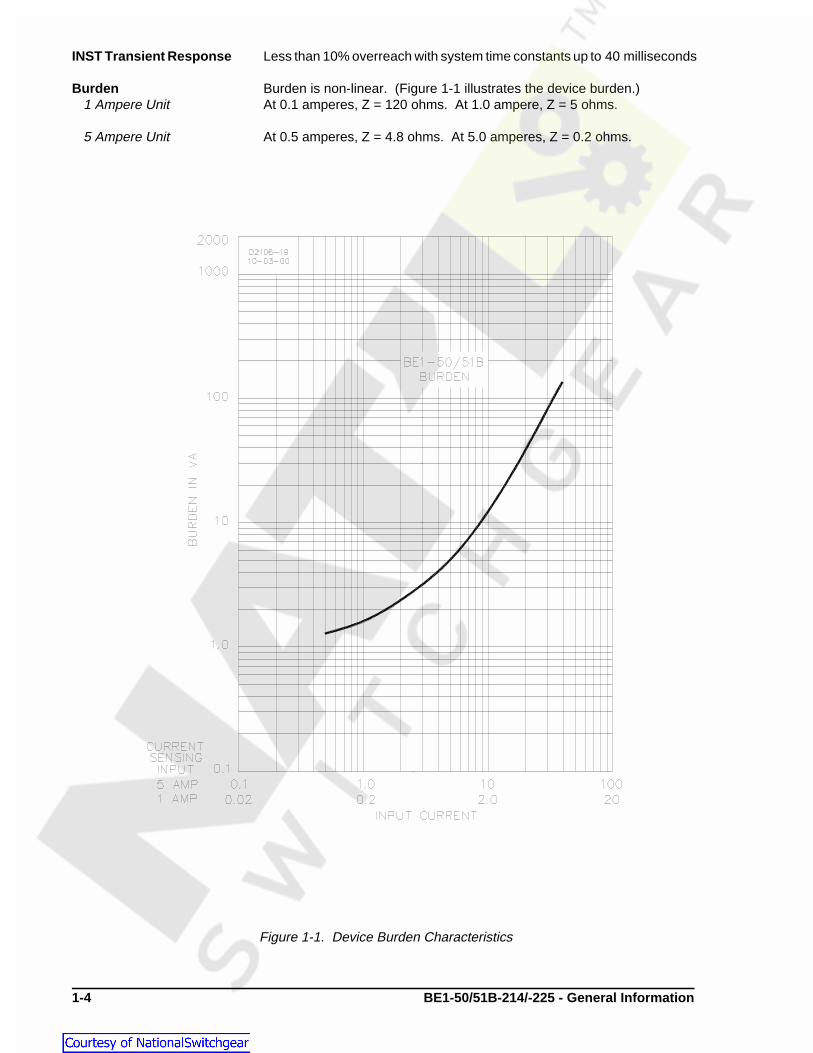
Figure 1-1. Device Burden Characteristics
INST Transient Response Less than 10% overreach with system time constants up to 40 milliseconds
Burden Burden is non-linear. (Figure 1-1 illustrates the device burden.)1 Ampere Unit At 0.1 amperes, Z = 120 ohms. At 1.0 ampere, Z = 5 ohms.
5 Ampere Unit At 0.5 amperes, Z = 4.8 ohms. At 5.0 amperes, Z = 0.2 ohms.

BE1-50/51B-214/-225 - General Information 1-5
Figure 1-2. Harmonic Rejection
Harmonic Response Harmonic rejection is illustrated in Figure 1-2.
Figure 1-2 shows that a relay set for one ampere pickup would pickup at0.96 ampere on a current containing 40% seventh harmonic. Thiscorresponds to a ten-to-one rejection ratio. Other conditions may beevaluated in the same manner.
INST Characteristics Instantaneous characteristic curves are similar to standardelectromechanical instantaneous units. However, the time to trip forapplications where the initial current through the relay is less than 0.4ampere (5 ampere relay) or 0.08 ampere (1 ampere relay) may be slightlylonger. This may occur on a very lightly loaded circuit or when the relay isproviding ground protection and is connected to measure neutral current.Figure 1-3 shows the instantaneous characteristic curves for maximumtime to trip.
An additional fixed delay of 0.1 second may be added with internal switchSW3-2. This delay applies to both phase and ground applications. Closingswitch SW3-2 provides an additional delay of 0.1 second. Section 2illustrates the location of SW3.
The instantaneous element in BE1-50/51B-214/-225 relays may be setlower than the instantaneous element in IAC relays and still have the samereach. This is because the BE1-50/51B-214/-225 instantaneous elementeffectively eliminates the fault current transient overreach components.When calculating BE1-50/51B-214/-225 relay instantaneous elementsettings, calculate the symmetrical value without any adder for transientoverreach.

1-6 BE1-50/51B-214/-225 - General Information
Figure 1-3. Instantaneous Characteristic Curves
TT �
AD
M N�C
�BD�K
Time Characteristics Nine inverse time functions and one fixed time function can be selected bya front panel switch. Characteristic curves for the inverse and definite timefunctions are defined by the following equation.
Where: TT = Time to trip in secondsD = TIME DIAL settingM = Multiple of PICKUP setting
A, B, C, N, K = Constants for the particular curve
Refer to Tables 1-3 or 1-4 for the time characteristic curve constants.Constants have been selected to conform to the characteristics ofelectromechanical relays over a range of pickup multiples from 1.3 to 40.Values of the constants are provided for use in computer relay settingprograms. Timing accuracy is ±1 cycle ±2% of time to trip.

BE1-50/51B-214/-225 - General Information 1-7
Time Characteristics - The fixed time characteristic provides delays of 0.0 to 9.9 secondsContinued corresponding to the time dial setting. The time set is constant over a
range of pickup multiples from 1.0 to 40. Accuracy is ±1 cycle ±2% of timeto trip for time dial settings of 0.1 and greater.
Table 1-3. Time Characteristic Curve Constants With SW3-3 Open (OFF)
Curve Type Figure Constants
BE1 Similar To Number A B C N K R
S ABB CO-2 1-5 0.2663 0.03393 1.000 1.2969 0.028 0.500
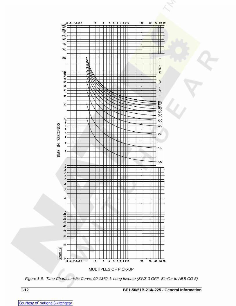
L ABB CO-5 1-6 5.6143 2.18592 1.000 1.000 0.028 15.750
D ABB CO-6 1-7 0.4797 0.21359 1.000 1.5625 0.028 0.875
M ABB CO-7 1-8 0.3022 0.12840 1.000 0.5000 0.028 1.750
I ABB CO-8 1-9 8.9341 0.17966 1.000 2.0938 0.028 9.000
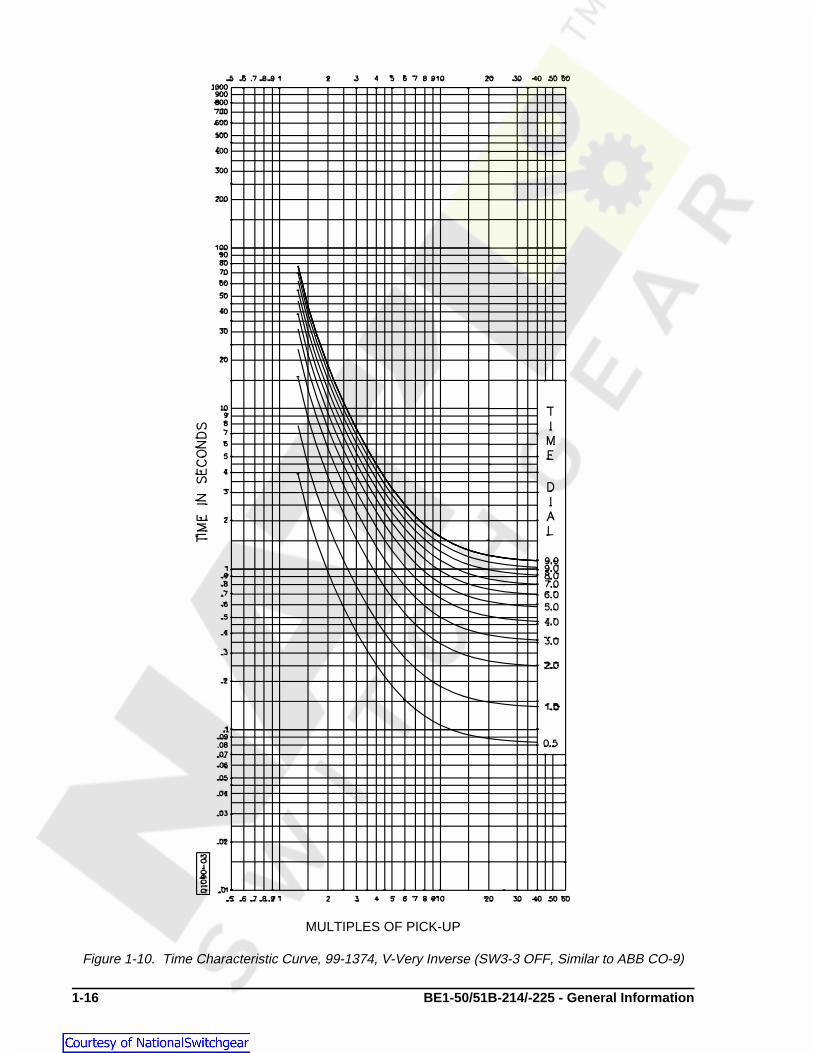
V ABB CO-9 1-10 5.4678 0.10814 1.000 2.0469 0.028 5.500
E ABB CO-11 1-11 7.7624 0.02758 1.000 2.0938 0.028 7.750
B BS142-B* 1-12 1.4636 0.00000 1.000 1.0469 0.028 3.250
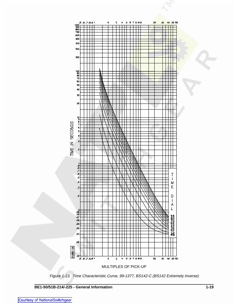
C BS142-C* 1-13 8.2506 0.00000 1.000 2.0469 0.028 8.000
F None** None 0.0000 1.00000 0.000 0.0000 0.000 1.000
* Curves B and C are defined in British Standard BS142 and IEC 255-4 (InternationalElectrotechnical Commission)
** Fixed time from 0.1 to 9.9 seconds.
BE1 Curve Types:
S = Short Inverse V = Very InverseL = Long Inverse E = Extremely InverseD = Definite Time B = BS142 Very InverseM = Moderately Inverse C = BS142 Extremely InverseI = Inverse F = Fixed Time
Table 1-4. Time Characteristic Curve Constants With SW3-3 Closed (ON)
Curve Type Figure Constants
BE1 Similar To Number A B C N K R
S GE IAC 55 1-14 0.0286 0.0208 1.000 0.9844 0.028 0.0940
L GE IAC 66 1-15 2.3955 0.00002 1.000 0.3125 0.028 7.8001
D ABB CO-6 1-7 0.4797 0.21359 1.000 1.5625 0.028 0.8750
M ABB CO-7 1-8 0.3022 0.12840 1.000 0.5000 0.028 1.7500
I GE IAC 51 1-16 0.2747 0.1042 1.000 0.4375 0.028 0.8868
V GE IAC 53 1-17 4.4309 0.0991 1.000 1.9531 0.028 5.8231
E GE IAC 77 1-18 4.9883 0.0129 1.000 2.0469 0.028 4.7742
B BS142-B* 1-12 1.4636 0.00000 1.000 1.0469 0.028 3.2500
C BS142-C* 1-13 8.2506 0.00000 1.000 2.0469 0.028 8.0000
F None** None 0.0000 1.00000 0.000 0.0000 0.000 1.0000

1-8 BE1-50/51B-214/-225 - General Information
TR �
RD
M 2�1
TT �
AD
M N�C
�BD�K � Time To Trip
TR �
RD
M 2�1
� Time To Reset
Integrating Time Reset Reset begins when the current drops below 95% of pickup. Integrating resetCharacteristic simulates the disk reset of electromechanical relays. BE1-50/51B-214/-
225 relays provide the integrating reset function even when input currentfalls to zero.
Integrating reset characteristics are defined by the following equation andshown in Figure 1-4. Equation constants are provided in Tables 1-2 or 1-3.
Where: TR = Time to reset in secondsR = Constant for the particular curveD = TIME DIAL settingM = Current in multiples of PICKUP setting during reset
Time characteristic curve equation.
Where: D = TIME DIAL settingM = Multiple of PICKUP setting
Reset characteristic curve equation.
Instantaneous Time Reset Resets within 16 milliseconds when current drops below pickup.Characteristic
Target Indicators Magnetically latched, manually reset targets indicate that current of 0.2amperes or greater was present in the trip circuit. Target coil resistance isless than 0.1 ohms and operate time is less than one millisecond. See50/51 Output specifications for maximum current rating.
50/51 Output Output contacts are surge protected and rated as follows:
Resistive:120/240 Vac Make 30 amperes for 0.2 seconds, carry 7 amperes for 2 minutes, 3
amperes continuously, and break 5 amperes.
125/250 Vdc Make 30 amperes for 0.2 seconds, carry 7 amperes for 2 minutes, 3amperes continuously, and break 0.3 ampere.
Inductive:120/240 Vac, Make and carry 30 amperes for 0.2 seconds, carry 7 amperes for 2 125/250 Vdc minutes, 3 amperes continuously, and break 0.3 ampere. 0.3 amperes.
(L/R = 0.04).

BE1-50/51B-214/-225 - General Information 1-9
1.0
10.0
100.0
0.0 0.2 0.4 0.6 0.8 1.0
Multiple of Pickup
xRD
(S
econ
ds)
Isolation Meets IEC 255-5 and exceeds IEEE C37.90-1989, one-minute dielectric(high potential) tests as follows:
All circuits to ground: 2828 VdcInput to Output Circuits: 2000 Vac or 2828 Vdc
This chart vertical axis xRD (Seconds) isapplicable for all curves and is derivedfrom multiplying the constant R for thecurve selected times D (the TIME DIALsetting).
Figure 1-4. Integrating Reset Characteristic Curve
Surge Withstand CapabilityOscillatory Qualified to IEEE C37.90.1-1989 Standard Surge Withstand Capability
(SWC) Tests for Protective Relays and Relay Systems.
Fast Transient Qualified to IEEE C37.90.1-1989 Standard Surge Withstand Capability(SWC) Tests for Protective Relays and Relay Systems.
Impulse Test Qualified to IEC 255-5.
Radio Frequency Field tested using a five watt, hand held transceiver operating at random Interference (RFI) frequencies centered around 144 megahertz and 440 megahertz, with the
antenna located six inches from the relay in both horizontal and verticalplanes.
Patent Patented in U.S., 1998, U.S. Patent No. 5751532.

1-10 BE1-50/51B-214/-225 - General Information
Temperature Operating Range-40�C (-40�F) to 70�C (158�F)
Recommended Storage Range-50�C (-58�F) to 50�C (122�F).
Shock 15 g in each of three mutually perpendicular planes.
Vibration 2 g in each of three mutually perpendicular planes swept over the range of10 to 500 hertz for a total of six sweeps, 15 minutes each sweep.
Weight 6.1 pounds.
CHARACTERISTIC CURVES
Figures 1-5 through 1-18 illustrate the characteristic curves that are programmed into the nonvolatilememory of this relay. To order full-size drawings of these characteristic curves, contact Customer ServiceDepartment of the Power Systems Group, Basler Electric, and request publication 9 2520 00 999. Thispublication contains fourteen full size characteristic curves on transparent paper (vellum).

BE1-50/51B-214/-225 - General Information 1-11
MULTIPLES OF PICK-UP
Figure 1-5. Time Characteristic Curve 99-1369, S-Short Inverse (SW3-3 OFF, Similar to ABB CO-2)
1-12 BE1-50/51B-214/-225 - General Information
MULTIPLES OF PICK-UP
Figure 1-6. Time Characteristic Curve, 99-1370, L-Long Inverse (SW3-3 OFF, Similar to ABB CO-5)

BE1-50/51B-214/-225 - General Information 1-13
MULTIPLES OF PICK-UP
Figure 1-7. Time Characteristic Curve, 99-1371, D-Definite Time (Similar to ABB CO-6)

1-14 BE1-50/51B-214/-225 - General Information
MULTIPLES OF PICK-UP
Figure 1-8. Time Characteristic Curve, 99-1372, M-Moderately Inverse (Similar to ABB CO-7)

BE1-50/51B-214/-225 - General Information 1-15
MULTIPLES OF PICK-UP
Figure 1-9. Time Characteristic Curve, 99-1373, I-Inverse (SW3-3 OFF, Similar to ABB CO-8)
1-16 BE1-50/51B-214/-225 - General Information
MULTIPLES OF PICK-UP
Figure 1-10. Time Characteristic Curve, 99-1374, V-Very Inverse (SW3-3 OFF, Similar to ABB CO-9)

BE1-50/51B-214/-225 - General Information 1-17
MULTIPLES OF PICK-UPFigure 1-11. Time Characteristic Curve, 99-1375, E-Extremely Inverse
(SW3-3 OFF, Similar to ABB CO-11)

1-18 BE1-50/51B-214/-225 - General Information
MULTIPLES OF PICK-UP
Figure 1-12. Time Characteristic Curve, 99-1376, BS142-B (BS142 Very Inverse)
BE1-50/51B-214/-225 - General Information 1-19
MULTIPLES OF PICK-UP
Figure 1-13. Time Characteristic Curve, 99-1377, BS142-C (BS142 Extremely Inverse)

1-20 BE1-50/51B-214/-225 - General Information
Figure 1-14. Time Characteristic Curve, 99-1595, S2-Short Inverse (SW3-3 ON, Similar to GE IAC 55)

BE1-50/51B-214/-225 - General Information 1-21
Figure 1-15. Time Characteristic Curve, 99-1594, L2-Long Inverse (SW3-3 ON, Similar To GE IAC 66)

1-22 BE1-50/51B-214/-225 - General Information
Figure 1-16. Time Characteristic Curve, 99-1597, I2-Inverse (SW3-3 ON, Similar To GE IAC 51)

BE1-50/51B-214/-225 - General Information 1-23
Figure 1-17. Time Characteristic Curve, 99-1596, V2-Very Inverse (SW3-3 ON, Similar To GE IAC 53)

1-24 BE1-50/51B-214/-225 - General Information
Figure 1-18. Time Characteristic Curve, 99-1598, E2-Extremely Inverse(SW3-3 ON, Similar To GE IAC 77)
BE1-50/51B-214/-225 - Human Machine Interface (Controls and Indicators) 2-1
SECTION 2 • HUMAN MACHINE INTERFACE(Controls and Indicators)
DESCRIPTION
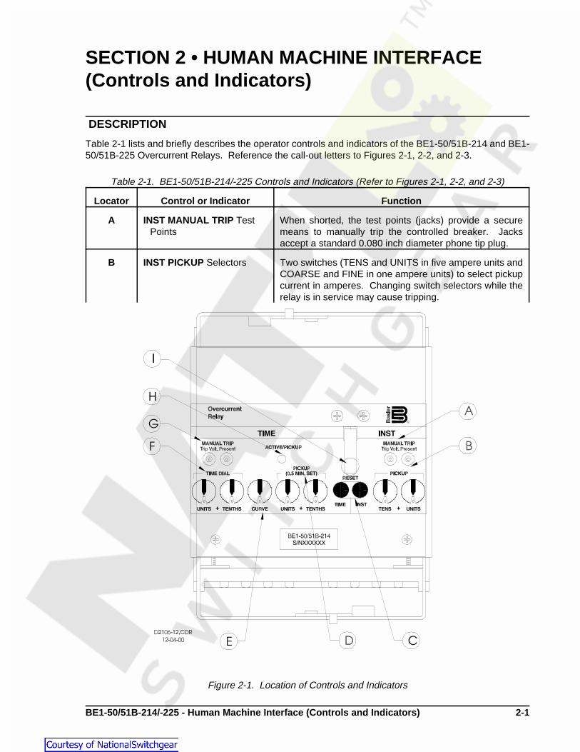
Table 2-1 lists and briefly describes the operator controls and indicators of the BE1-50/51B-214 and BE1-50/51B-225 Overcurrent Relays. Reference the call-out letters to Figures 2-1, 2-2, and 2-3.
Table 2-1. BE1-50/51B-214/-225 Controls and Indicators (Refer to Figures 2-1, 2-2, and 2-3)
Locator Control or Indicator Function
A INST MANUAL TRIP TestPoints
When shorted, the test points (jacks) provide a securemeans to manually trip the controlled breaker. Jacksaccept a standard 0.080 inch diameter phone tip plug.
B INST PICKUP Selectors Two switches (TENS and UNITS in five ampere units andCOARSE and FINE in one ampere units) to select pickupcurrent in amperes. Changing switch selectors while therelay is in service may cause tripping.
Figure 2-1. Location of Controls and Indicators

2-2 BE1-50/51B- 214/-225 - Human Machine Interface (Controls and Indicators)
Table 2-1. BE1-50/51B-214 Controls and Indicators - Continued
Locator Control or Indicator Function
C Targets Black target indicators trip to red and magnetically latchwhen the trip circuit current is greater than 0.2 amperes.One target each for TIME and INST.
D TIME PICKUP Selectors Two switches (UNITS and TENTHS in five ampere unitsand COARSE and FINE in one ampere units) to selectpickup current in amperes. Changing switch selectorswhile the relay is in service may cause tripping.
E CURVE Selector Ten position selector switch to select one of nine inversefunctions or one fixed time function.
F TIME DIAL Selectors Two selector switches (UNITS and TENTHS) to select thedesired characteristic curve. A setting of 0.0 results ininstantaneous operation without any intentional delay. Asetting of 9.9 corresponds to the typical time provided byan electromechanical relay at its maximum dial setting.
G TIME MANUAL TRIP TestPoints
When shorted, the test points provide a secure means tomanually trip the controlled breaker. Jacks accept astandard 0.080 inch diameter phone tip plug.
H ACTIVE/PICKUP LED Red LED indicates sensed current has exceeded the TIMEPICKUP setting. LED turns from red to green when sensedcurrent falls below 95 % of pickup setting. When the LEDis green, the relay is active but has not picked up.
I Target Reset Lever Linkage extends through back of front cover to reset bothmagnetically latched target indicators.
J SW3 -1 SW3-1 selects the system operating frequency. SW3-1open (OFF) selects 60 hertz operation. SW3-1 closed(ON) selects 50 hertz operation.
SW3-2
SW3-3
SW3-4
SW3-2 provides additional time delay for the instantaneouselement. Closing switch SW3-2 (ON) provides anadditional instantaneous delay of 0.1 second.
SW3-3 provides selection of GE IAC type curves or ABBtype curves. Closing switch SW3-3 (ON) selects GE IACtype curves (refer to Table 1-3). Opening switch SW3-3(OFF) selects ABB type curves (refer to Table 1-2).
SW3-4 provides selection of either instantaneous orintegrating reset characteristics. Closing SW3-4 (ON)selects integrating reset characteristics. Opening SW3-4(OFF) selects instantaneous reset characteristics.
Note: For BE1-50/51B-214, unit revisions J and previous,SW3 is labeled SW8.

BE1-50/51B-214/-225 - Human Machine Interface (Controls and Indicators) 2-3
Figure 2-2. Location of Controls and Indicators

2-4 BE1-50/51B- 214/-225 - Human Machine Interface (Controls and Indicators)
Figure 2-3. Location of Controls and Indicators

BE1-50/51B-214/-225 - Functional Description 3-1
SECTION 3 • FUNCTIONAL DESCRIPTION
GENERAL
BE1-50/51B-214/-225 Overcurrent Relays are microprocessor based non-directional relays that measureac current to provide secure and reliable instantaneous and time overcurrent protection for power systems.
FUNCTIONAL DESCRIPTION
Sensing Input
Single phase ac current from system current transformers (CT) is brought into the BE1-50/51B-214/-225Overcurrent Relay at terminals five and six. Refer to Figure 3-1 to follow the functional description. Theinput current is applied to internal power and signal CTs.
Power Supply
Current from the power CT is rectified, filtered, and supplied to all relay internal circuitry for operating power.A precision +5 Vdc supply also serves as a reference for automatic calibration.
Instantaneous Signal
Current from the signal CT is rectified and applied to the instantaneous scaling resistors controlled by theINST PICKUP selector switches. The analog voltage of the instantaneous input signal developed acrossthe scaling resistors is filtered and applied to the multiplexor (MUX).
Time Signal
Current from the signal CT is also rectified and applied to the time scaling resistors controlled by the TIMEPICKUP selector switches. The analog voltage of the time input signal is also filtered and applied to themultiplexor.
Microprocessor
Operating power from the power supply is applied to the microprocessor supervisor circuit. When themicroprocessor is active and executing code, the ACTIVE/PICKUP LED is green. When the input currentfalls below an acceptable level, the supervisor circuit interrupts the microprocessor, halts further operation,and turns OFF the ACTIVE/PICKUP LED. A microprocessor watchdog feature resets the microprocessorprogram when the program flow is interrupted.
Information from the TIME DIAL selector switches, the TIME CURVE selector switch, and the 50/60 Hz, INSTDELAY, and RESET CHAR switches is also applied to the microprocessor. The microprocessor uses theseinputs to set the operating parameters.
When the microprocessor is ready for analog information from the multiplexor, microprocessor controlsignals cause the multiplexor to route the desired input through to the output. The output is converted froman analog value to a digital value and applied to the microprocessor.
The microprocessor performs the program operations based on the inputs and the internal softwareprogram. When the sensed current exceeds the TIME PICKUP setting, the ACTIVE/PICKUP LED turns fromgreen to red. TIME contacts (51) are closed in accordance with the time characteristic equation. If thesensed current exceeds the INST PICKUP setting, the INST contacts (50) are closed.
Power-Off Sensing
Power-off sensing circuits measure the voltage across a capacitor at power-down and at power-up. Thesecircuits determine how long power has been removed based on the difference voltage and the circuit RCtime constant. This provides information for the integrating reset function even when power has beenentirely removed.

3-2 BE1-50/51B-214/-225 - Functional Description
CAUTIONTrip circuit voltage is present at the front panel test points. When shorting the testpoints, use insulated jumpers to avoid contact with these voltages.
Outputs
Instantaneous And Timed
System circuit breakers controlled by the output contacts can be manually tripped by applying a short acrossthe TIME or INST MANUAL TRIP front panel test points. Current flow in the trip circuit is indicated by theoperation of the target. The targets will not operate without adequate operating power for the relay.
Figure 3-1. Functional Block Diagram

BE1-50/51B-214/-225 - Installation 4-1
SECTION 4 • INSTALLATION
GENERAL
When not shipped as part of a control or switchgear panel, the relays are shipped in sturdy cartons to preventdamage during transit. Immediately upon receipt of a relay, check the model and part number against therequisition and packing list to see that they agree. Visually inspect the relay for damage that may have occurredduring shipment. If there is evidence of damage, immediately file a claim with the carrier and notify the RegionalSales Office, or contact the Sales Representative at Basler Electric, Highland, Illinois.
Proper operation of the relay may be confirmed by performing the operational test procedure (Section 5). In theevent the relay is not to be installed immediately, store the relay in its original shipping carton in a moisture anddust free environment.
DIELECTRIC TEST
In accordance with IEC 255-5 and IEEE C37.90-1989, one-minute dielectric (high potential) tests may beperformed as shown in the following paragraphs. Output contacts are surge protected.
All circuits to ground: 2828 VdcInput to output circuits: 2000 Vac or 2828 Vdc
MOUNTING
Because the relay is of solid state design, it does not have to be mounted vertically. Any convenient mountingangle may be chosen.
FACTORY SETTINGSFactory settings for the internal switches of SW3 are as follows:
• SW3-1 — OFF (60 hertz operation).• SW3-2 — OFF (0.0 additional fixed delay for the instantaneous element).• SW3-3 — ON (GE IAC type characteristic curves).• SW3-4 — ON (Integrating reset characteristics).
INSTALLATION
Select the desired relay settings before putting the relay into service. Changing pickup current settings whilethe relay is in service may cause tripping. Perform the following procedures to install the BE1-50/51B-214 orBE1-50/51B-225 relay.
• Remove the existing relay.• Use the four screws provided and attach the cover adapter to the existing case.• Insert the new BE1-50/51B-214 or BE1-50/51B-225 relay and close the cradle latches locking the relay
into the case.• Reinstall the existing connection plug.• to install the cover, position the interlocking bracket at the top of the new Basler Electric cover into the
mating receptacle at the top of the cover adapter plate. Secure the captive fastener at the bottom of thecover.

4-2 BE1-50/51B-214/-225 - Installation
TTrip �AD
M N�C
�BD�K
�7.7624×2
102.0938�1
� (0.02758×2) � 0.028
�15.5248
124.10806�1� (0.05516) � 0.028
� 0.209 seconds
TReset �RD
M 2�1
�7.75×2
02�1
� �15.5 seconds
Figure 4-1. Coordination Timing Diagram
APPLICATION COORDINATION
In a typical application coordination scheme, a BE1-50/51B-214 or BE1-50/51B-225 is being used to provideprimary protection for a radial distribution feeder. An electromechanical overcurrent relay with extremely inversetiming provides protection for the transformer and bus. To improve coordination with the electromechanicalrelay, the BE1 relay with integrating reset characteristic has the time characteristic curve E (extremely inverse)selected (SW3-3 set to OFF) and the TIME DIAL set to 2.0. The feeder reclosing relay is set for two recloseattempts at 3 and 15 seconds after the initial trip. If a permanent fault occurs (magnitude ten times pickup),calculate the feeder breaker trip time for each of the three operations. Refer to Section 1 for characteristic curveconstants.
From the time characteristic curve equation.
From the reset characteristic curve equation.
M = 0 if current goes to zero.Negative result indicates reset time.
Results: Full trip = 0.209 seconds and full reset = 15.5 seconds if current goes to zero.
In Figure 4-1,
TA = 0.209 seconds (relay was at reset).TB = value < TA because rewind has not gone to zero.TC = value < TA because rewind has not gone to zero.

BE1-50/51B-214/-225 - Installation 4-3
TTrip This Occurance �(Full Trip)(Rewind Time)
Full Rewind
TB �(0.209)(3)
15.5
TB � 0.040 seconds
TC �(0.209)(11.96)
15.5
TC � 0.161 seconds
Equation for time to trip during rewind (before relay is reset).
Second Operation
Third Operation
CONNECTIONS
Typical ac input and dc control connections are shown in Figures 4-2 and 4-3. Refer to Section 3, block diagramfor relay internal connections.
Figure 4-2. AC Input Connections

4-4 BE1-50/51B-214/-225 - Installation
Figure 4-3. DC Control Connections

BE1-50/51B-214/-225 - Testing 5-1
CAUTIONTo ensure proper timing during testing, before each test, remove the current from theunit for R times D seconds (refer to Section 1, Specifications, Time Reset for R and Ddefinitions).
SECTION 5 • TESTING
GENERAL
When not shipped as part of a control or switchgear panel, the relays are shipped in sturdy cartons toprevent damage during transit. Immediately upon receipt of a relay, check the model and part numberagainst the requisition and packing list to see that they agree. Visually inspect the relay for damage that mayhave occurred during shipment. If there is evidence of damage, immediately file a claim with the carrier andnotify the Regional Sales Office, or contact the Sales Representative at Basler Electric, Highland, Illinois.
Proper operation of the relay may be confirmed by performing the operational test procedures in this Section.In the event the relay is not to be installed immediately, store the relay in its original shipping carton in amoisture and dust free environment.
DIELECTRIC TEST
In accordance with IEC 255-5 and IEEE C37.90-1989, one-minute dielectric (high potential) tests may beperformed as follows:
All circuits to ground: 2828 Vdc.Input to output circuits: 2000 Vac or 2828 Vdc.
Output contacts are surge protected.
OPERATIONAL TEST PROCEDURE
The following procedures verify operation of relays BE1-50/51B-214 (5 ampere model) and BE1-50/51B-225(1 ampere model). The test setup of Figures 5-1 and 5-2 (showing the BE1-50/51B-214) are intendedprimarily as an illustration of the principles involved. Other test setups known to be capable of testing withthe stated and implied tolerances (including equipment specifically designed for testing relays) may be used.
Test Equipment Required� Current source with a range from 0 to 20 amperes ac (sensing input current).� Current source 0.2 to 3 amperes ac (target operation).� Timer or counter.

5-2 BE1-50/51B-214 /-225- Testing
BE1-50/51B-214
6 5 3 1
TIMEINST
2
CURRENTSOURCE
INPUTSTOP TIMER
START
AMPS
TEST SET
12-09-99D1148-25.vsd
BE1-50/51B-214
6 5
C U R R E N TS O U R C E
INPUTS T O P TIMER
START
AMPS
TEST SET
12-09-99D1148-24.vsd
1.0AC U R R E N T
LIMITER
TARGET CURRENT
23
INST
1
TIME
Figure 5-1. Pickup And Timing Test Setup
Figure 5-2. Target Operational Test Setup

BE1-50/51B-214/-225 - Testing 5-3
NOTEWhen testing TIME overcurrent functions, INST PICKUP settings of 00 will affect thecalibration of the TIME functions. TIME PICKUP settings of 00 also affect INSTfunctions.
Test Procedure, Models BE1-50/51B-214 (Five Ampere Sensing Input)
Time Pickup Test
Perform preliminary setup:
• Connect test setup as shown in Figure 5-1.• Insure that SW3 switches are set: SW3-1 for the operating frequency, SW3-2 to OFF, SW3-3 to ON,
and SW3-4 to ON.• Set TIME DIAL to 0.0.• Set CURVE to S• Set TIME PICKUP to 0.5.• Set INST PICKUP to 90.
Step 1. Slowly increase current to terminals 5 and 6. PICKUP LED should turn RED at a maximum inputcurrent of 0.550 ampere.
Step 2. Decrease input current until PICKUP LED turns GREEN then OFF.
Step 3. Set TIME PICKUP to 2.2.
Step 4. Slowly increase current to terminals 5 and 6. PICKUP LED should change from GREEN to REDat an input current of 2.131 to 2.269 amperes.
Step 5. Decrease input current until PICKUP LED turns OFF.
INST Pickup Test
Perform preliminary setup:
• Connect test setup as shown in Figure 5-1.• Insure that SW3 switches are set: SW3-1 for the operating frequency, SW3-2 to OFF, SW3-3 to ON,
and SW3-4 ON.• Set TIME DIAL to 0.0.• Set CURVE to S• Set TIME PICKUP to 1.0.• Set INST PICKUP to 01.
Step 1. Slowly increase current to terminals 5 and 6. INST contacts should close at an input current of0.955 to 1.045 amperes.
Step 2. Decrease input current until INST output contacts open.
Step 3. Set INST PICKUP to 08.
Step 4. Slowly increase current to terminals 5 and 6. INST contacts should close at an input current of7.815 to 8.185 amperes.
Step 5. Decrease input current until INST output contacts open.

5-4 BE1-50/51B-214 /-225- Testing
Time Dial Test
Perform preliminary setup:
• Connect test setup as shown in Figure 5-1.• Insure that SW3 switches are set: SW3-1 for the operating frequency, SW3-2 to OFF, SW3-3 to ON,
and SW3-4 ON.• Set TIME DIAL to 4.5.• Set CURVE to S• Set TIME PICKUP to 1.0.• Set INST PICKUP to 90.
Step 1. Prepare to apply 1.5 amperes input current to terminals 5 and 6 and record the elapsed time fromwhen current is applied until TIME output contacts close.
Step 2. Apply the current (step from 0 to 1.5 amperes) and record the elapsed time. Elapsed time shouldbe 0.345 to 0.424 seconds. (This tolerance is greater than ±2 % because it is the accumulation ofboth pickup and timing tolerances.)
Step 3. Remove input current.
Target Test
Perform preliminary setup:
• Connect test setup as shown in Figure 5-2.• Insure that SW3 switches are set: SW3-1 for the operating frequency, SW3-2 to OFF, SW3-3 to ON,
and SW3-4 ON.• Set TIME DIAL to 4.5.• Set CURVE to S• Set TIME PICKUP to 1.0.• Set INST PICKUP to 01.
Step 1. Set target current source to 1.0 ampere, ac.
Step 2. Apply 5 amperes input current to terminals 5 and 6. Check that both TIME and INST targetsoperate.
Step 3. Remove input current and reset targets.
Manual Trip Test
Perform preliminary setup:
• Connect test setup as shown in Figure 5-2.• Insure that SW3 switches are set: SW3-1 for the operating frequency, SW3-2 to OFF, SW3-3 to ON,
and SW3-4 ON.• Set TIME DIAL to 4.5.• Set CURVE to S• Set TIME PICKUP to 1.0.• Set INST PICKUP to 01.

BE1-50/51B-214/-225 - Testing 5-5
CAUTIONTrip circuit voltage is present at the front panel test points. When shorting the testpoints, use insulated jumpers to avoid contact with these voltages.
Step 1. Set target current source to 1.0 ampere, ac.
Step 2. Apply 0.9 ampere input current to terminals 5 and 6. (0.9 ampere provides input power but staysbelow pickup.)
Step 3. Connect a jumper between TIME MANUAL TRIP test points. Check that TIME target operates.
Step 4. Connect a jumper between INST MANUAL TRIP test points. Check that INST target operates.
Step 5. Reset targets.
Integrating Reset Test
Perform preliminary setup:
• Connect test setup as shown in Figure 5-1.• Insure that SW3 switches are set: SW3-1 for the operating frequency, SW3-2 to OFF, SW3-3 to ON,
and SW3-4 ON.• Set TIME DIAL to 9.9.• Set CURVE to V.• Set TIME PICKUP to 1.0.• Set INST PICKUP to 90.
Step 1. Set target current source to 1.0 ampere, ac.
Step 2. Read all of Step 3 before beginning Step 3.
Step 3. Apply 4.0 amperes input current to terminals 5 and 6. After the unit trips, remove the input currentfor 29 ±0.25 seconds, then reapply the 4.0 amperes input current. Record the elapsed time fromthe reapplication of input current to the output retrip.
Result: Elapsed time should be 2.08 ±0.4 seconds.
Test Procedure, Models BE1-50/51B-225 (One Ampere Sensing Input)
Time Pickup Test
Perform preliminary setup:
• Connect test setup as shown in Figure 5-1.• Insure that SW3 switches are set: SW3-1 for the operating frequency, SW3-2 to OFF, SW3-3 to ON,
and SW3-4 to ON.• Set TIME DIAL to 0.0.• Set CURVE to S• Set TIME PICKUP to 0.5.• Set INST PICKUP to 18.0.
Step 1. Slowly increase current to terminals 5 and 6. PICKUP LED should turn RED at a maximum inputcurrent of 0.110 ampere.
Step 2. Decrease input current until PICKUP LED turns GREEN then OFF.

5-6 BE1-50/51B-214 /-225- Testing
Step 3. Set TIME PICKUP to 0.44.
Step 4. Slowly increase current to terminals 5 and 6. PICKUP LED should change from GREEN to REDat an input current of 0.426 to 0.454 amperes.
Step 5. Decrease input current until PICKUP LED turns OFF.
INST Pickup Test
Perform preliminary setup:
• Connect test setup as shown in Figure 5-1.• Insure that SW3 switches are set: SW3-1 for the operating frequency, SW3-2 to OFF, SW3-3 to ON,
and SW3-4 ON.• Set TIME DIAL to 0.0.• Set CURVE to S• Set TIME PICKUP to 3.02.• Set INST PICKUP to 0.2
Step 1. Slowly increase current to terminals 5 and 6. INST contacts should close at an input current of0.191 to 0.209 amperes.
Step 2. Decrease input current until INST output contacts open.
Step 3. Set INST PICKUP to 08.
Step 4. Slowly increase current to terminals 5 and 6. INST contacts should close at an input current of1.563 to 1.637 amperes.
Step 5. Decrease input current until INST output contacts open.
Time Dial Test
Perform preliminary setup:
• Connect test setup as shown in Figure 5-1.• Insure that SW3 switches are set: SW3-1 for the operating frequency, SW3-2 to OFF, SW3-3 to ON,
and SW3-4 ON.• Set TIME DIAL to 4.5.• Set CURVE to S• Set TIME PICKUP to 0.2.• Set INST PICKUP to 18.0.
Step 1. Prepare to apply 0.3 amperes input current to terminals 5 and 6 and record the elapsed time fromwhen current is applied until TIME output contacts close.
Step 2. Apply the current (step from 0 to 0.3 amperes) and record the elapsed time. Elapsed time shouldbe 1.754 to 2.084 seconds. (This tolerance is greater than ±2 % because it is the accumulation ofboth pickup and timing tolerances.)
Step 3. Remove input current.
Target Test
Perform preliminary setup:
• Connect test setup as shown in Figure 5-2.• Insure that SW3 switches are set: SW3-1 for the operating frequency, SW3-2 to OFF, SW3-3 to ON,

BE1-50/51B-214/-225 - Testing 5-7
CAUTIONTrip circuit voltage is present at the front panel test points. When shorting the testpoints, use insulated jumpers to avoid contact with these voltages.
and SW3-4 ON.• Set TIME DIAL to 4.5.• Set CURVE to S• Set TIME PICKUP to 0.2.• Set INST PICKUP to 0.2.
Step 1. Set target current source to 1.0 ampere, ac.
Step 2. Apply 1 ampere input current to terminals 5 and 6. Check that both TIME and INST targets operate.
Step 3. Remove input current and reset targets.
Manual Trip Test
Perform preliminary setup:
• Connect test setup as shown in Figure 5-2.• Insure that SW3 switches are set: SW3-1 for the operating frequency, SW3-2 to OFF, SW3-3 to ON,
and SW3-4 ON.• Set TIME DIAL to 4.5.• Set CURVE to S• Set TIME PICKUP to 0.2.• Set INST PICKUP to 0.2.
Step 1. Set target current source to 1.0 ampere, ac.
Step 2. Apply 0.15 ampere input current to terminals 5 and 6. (0.15 ampere provides input power but staysbelow pickup.)
Step 3. Connect a jumper between TIME MANUAL TRIP test points. Check that TIME target operates.
Step 4. Connect a jumper between INST MANUAL TRIP test points. Check that INST target operates.
Step 5. Reset targets.
Integrating Reset Test
Perform preliminary setup:
• Connect test setup as shown in Figure 5-1.• Insure that SW3 switches are set: SW3-1 for the operating frequency, SW3-2 to OFF, SW3-3 to ON,
and SW3-4 ON.• Set TIME DIAL to 4.5.• Set CURVE to I.• Set TIME PICKUP to 0.20.• Set INST PICKUP to 18.0.
Step 1. Set target current source to 1.0 ampere, ac.
Step 2. Read all of Step 3 before beginning Step 3.

5-8 BE1-50/51B-214 /-225- Testing
Step 3. Apply 0.8 amperes input current to terminals 5 and 6. After the unit trips, remove the input currentfor 20 ±0.25 seconds, then reapply the 0.8 amperes input current. Record the elapsed time fromthe reapplication of input current to the output retrip.
Result: Elapsed time should be 1.55 ±0.3 seconds.
SETTING THE RELAY
Select the desired relay settings before putting the relay into service. Changing pickup current settings whilethe relay is in service may cause tripping.
PERIODIC TESTS
General
All relays should be tested periodically to identify and correct any problems that are found.
Single phase relays such as the BE1-50/51B-214 are normally used in groups of four (three phase andground) on the protected circuit. This relay scheme allows each unit to be withdrawn one at a time fortesting purposes without loosing protection. Only three are required at any one time to sense all types offaults on a grounded wye system. Refer to Figures 5-1 and 5-2 for recommended test setups.
Periodic Test
Periodic testing should consist of the following procedures.
Step 1. Verify that the instantaneous pickup is within ±2% of the value set on the dials. Pickup occurs whenthe INST output contacts close.
Step 2. Verify that the time pickup is within ±2% of the value set on the dials. Pickup occurs when the LEDturns GREEN then RED.
Step 3. Verify that the time to trip for the curve and time dial settings at a multiple of six is the same as thetime given on the characteristic curve. Refer to Section 1 for the characteristics curves.
Step 4. Verify that the time to trip for the instantaneous element at a pickup multiple of 2 is not greater thanthe time given on the instantaneous characteristic curve. Refer to Section 1 for the instantaneouscharacteristic curve.
Step 5. Verify that the targets operate with one ac ampere of trip current in the trip circuits and that they canbe reset using the RESET LEVER.
This completes the periodic test.

BE1-50/51B-214/-225 - Maintenance 6-1
CAUTIONSubstitution of printed circuit boards or individual components does not necessarilymean the relay will operate properly. Always test the relay before placing it in operation.
SECTION 6 • MAINTENANCE
GENERAL
BE1-50/51B-214/-225 Overcurrent Relays require no preventive maintenance. However, periodic checks shouldbe performed according to scheduled practices. A recommended periodic test is provided in this section. If therelay fails to function properly and in-house repair is considered, contact the Customer Service Department ofthe Power Systems Group, Basler Electric, for a return authorization number prior to shipping.
IN-HOUSE REPAIR
In-house replacement of individual components should be performed by qualified technicians.
When complete boards or assemblies are needed, the following information is required.
1. Relay model number2. Relay serial number
STORAGE
This protective relay contains long life aluminum electrolytic capacitors. Life in excess of 20 years may beexpected if the storage temperature does not exceed 40�C (72�F).
PERIODIC TESTS
General
All relays should be tested periodically to identify and correct any problems that are found.
Single phase relays such as the BE1-50/51B-214 are normally used in groups of four (three phase and ground)on the protected circuit. Only three are required at any one time to provide complete protection. The fourth oneassures that protection is maintained even if one relay failed.
This protection scheme also allows one unit at a time to be withdrawn from service for testing purposes withoutlosing protection during the test. Refer to Section 5 for recommended test setups.
Periodic Test
Periodic testing should consist of the following procedures.
Step 1. Verify that the instantaneous pickup is within ±2% of the value set on the dials. Pickup occurs when theINST output contacts close.
Step 2. Verify that the time pickup is within ±2% of the value set on the dials. Pickup occurs when the LEDchanges from GREEN to RED.

6-2 BE1-50/51B-214/-225 - Maintenance
Step 3. Verify that the time to trip for the curve and time dial settings at a multiple of six is the same as the timegiven on the characteristic curve. Refer to Section 1 for the characteristics curves.
Step 4. Verify that the time to trip for the instantaneous element at a pickup multiple of 2 is not greater than thetime given on the instantaneous characteristic curve. Refer to Section 1 for the instantaneouscharacteristic curve.
Step 5. Verify that the targets operate with one ac ampere of trip current in the trip circuits and that they can bereset using the RESET LEVER.
This completes the periodic test.

BE1-50/51B-214/-225 - Manual Change Information 7-1
SECTION 7 • MANUAL CHANGE INFORMATION
SUMMARY AND CROSS REFERENCE GUIDE
This section contains information concerning the previous editions of the manual. The substantive changes todate are summarized in Table 7-1.
Table 7-1. Changes
Revision Summary of Changes ECA/ECO/Date
A Changed all references to SW8-4 being field selectable. ECR 15202sealed SW8-4 in the integrating reset position.
15207/08-08-95
B Corrected minor typographical errors in Sections 1 and 2. ChangedFigure 5-2 and all references for testing target current source from 0.2ampere to 1.0 ampere.
15325/10-26-95
C Incorporated changes in the relay that added five characteristic curvesand provided for curve group (GE IAC or ABB) selection. ChangedSection 5, Testing to use the GE IAC curve group.
15435/12-06-95
D Added Patent number to Specifications. Changed manual format toreflect the current style.
16768/05-21-98
E Changed all references to target test current to one ampere alternatingcurrent. Deleted Step 5 in Section 6, Periodic Test.
7356/12-10-99
F Updated drawings in Section 2 to reflect changes to the PC board. Alsoupdated the rest of the manual to reflect the change in switch call outfrom SW8 to SW3. Added new functionality to the PICKUP LED. It isnow the ACTIVE/PICKUP LED and will be green when active and redwhen picked up.
11566/12-01-00
G Added the necessary information for part number 9 2520 00 225, oneampere nominal sensing input to all Sections of the manual asappropriate.
12837/03-30-00

ROUTE 143, BOX 269HIGHLAND, IL 62249 USA
http://www.basler.com, [email protected] 618-654-2341 FAX 618-654-2351