Embed Size (px)
Citation preview
1
INSTRUCTION MANUALAND
SAFETY INSTRUCTIONSFOR
CORDLESS IMPACT DRIVER
Variable speed
MODEL WH 8DC2
WARNING:Improper and unsafe use of this power tool can result indeath or serious bodily injury!This manual contains important information about productsafety. Please read and understand this manual beforeoperating the power tool. Please keep this manual availablefor others before they use the power tool.
2
CONTENTS
PageIMPORTANT INFORMATION .................................................................................... 3MEANINGS OF SIGNAL WORDS ............................................................................. 3
SAFETYIMPORTANT SAFETY INSTRUCTIONS
FOR USING ALL POWER TOOLS.................................................................... 4IMPORTANT SAFETY INSTRUCTIONS
FOR USE OF THE CORDLESS IMPACT DRIVER ............................................ 7IMPORTANT SAFETY INSTRUCTIONS
FOR BATTERY CHARGER................................................................................ 7IMPORTANT SAFETY INSTRUCTIONS
FOR USE OF THE BATTERY AND BATTERY CHARGER ............................... 9DISPOSAL OF THE EXHAUSTED BATTERY ....................................................... 10
OPERATION AND MAINTENANCEMODEL .................................................................................................................. 11NAME OF PARTS .................................................................................................. 11SPECIFICATIONS .................................................................................................. 12ACCESSORIES ...................................................................................................... 13
STANDARD ACCESSORIES ............................................................................ 13OPTIONAL ACCESSORIES .............................................................................. 13
APPLICATIONS ..................................................................................................... 14REMOVAL AND INSTALLATION METHOD OF BATTERY ................................. 15CHARGING METHOD ........................................................................................... 15PRIOR TO OPERATION......................................................................................... 17HOW TO USE ........................................................................................................ 18OPERATIONAL CAUTIONS .................................................................................. 19MAINTENANCE AND INSPECTION..................................................................... 20STORAGE .............................................................................................................. 21SERVICE AND REPAIRS ....................................................................................... 21PARTS LIST ........................................................................................................... 22
3
IMPORTANT INFORMATION
Read and understand all of the operating instructions, safety precautions andwarnings in the Instruction Manual before operating or maintaining this power tool.
Most accidents that result from power tool operation and maintenance are causedby the failure to observe basic safety rules or precautions. An accident can often beavoided by recognizing a potentially hazardous situation before it occurs, and byobserving appropriate safety procedures.
Basic safety precautions are outlined in the “SAFETY” section of this InstructionManual and in the sections which contain the operation and maintenance instruc-tions.
Hazards that must be avoided to prevent bodily injury or machine damage areidentified by WARNINGS on the power tool and in this Instruction Manual.
Never use this power tool in a manner that has not been specifically recommendedby HITACHI, unless you first confirm that the planned use will be safe for you andothers.
The warranty of this power tool is separately packed. Before using this power tool,make sure to thoroughly read and understand the content of the warranty.
MEANINGS OF SIGNAL WORDS
WARNING indicates a potentially hazardous situations which, if ignored, couldresult in serious personal injury.
CAUTION indicates a hazardous situations which, if ignored, could result inmoderate personal injury, or could cause machine damage.
NOTE emphasizes essential information.
4
SAFETY
IMPORTANT SAFETY INSTRUCTIONSFOR USING ALL POWER TOOLS
WARNING: Death or serious bodily injury could result from improper or
unsafe use of power tools. To avoid these risks, follow these
basic safety instructions:
READ ALL INSTRUCTIONS1. NEVER TOUCH MOVING PARTS.
Never place your hands, fingers or other body parts near the tool’s movingparts.
2. NEVER OPERATE WITHOUT ALL GUARDS IN PLACE.
Never operate this tool without all guards or safety features in place and inproper working order. If maintenance or servicing requires the removal of aguard or safety feature, be sure to replace the guard or safety feature beforeresuming operation of the tool.
3. ALWAYS WEAR EYE AND EAR PROTECTION.
Protect yourself from flying or expelled wood chips, metal particles or otherdebris by using safety goggles or equivalent eye protection. Wear ear protec-tion to protect yourself from excessive noise.
4. AVOID UNINTENTIONAL STARTING.
Don’t carry the tool with your finger near the power switch.5. STORE TOOL PROPERLY.
When not in use, the tool should be stored in a dry place. Keep out of reach ofchildren. Lock-out the storage area.
6. KEEP WORK AREA CLEAN.
Cluttered areas and benches invite injuries.Clear all work areas and work benches of unnecessary tools, debris, furniture,etc.
7. CONSIDER WORK AREA ENVIRONMENT.
Don’t expose power tools to rain.Don’t use power tools in damp or wet locations.Keep work area well lit and well ventilated.Don’t use tool in presence of flammable liquids or gases.
Power tools produce sparks during operation. They also spark whenswitching ON/OFF. Never use power tools in sites containing lacquer, paint,benzine, thinner, gasoline, gases, adhesive agents, and other materialswhich are combustible or explosive.
5
8. KEEP CHILDREN AWAY.
Do not let visitors contact tool.All visitors should be kept safely away from work area.
9. DON’T FORCE TOOL.
It will do the job better and safer at the rate for which it was intended.10. USE RIGHT TOOL.
Don’t force small tool or attachment to do the job of a heavy-duty tool.Don’t use tool for purpose not intended – for example – don’t use circular sawfor cutting tree limbs or logs.
11. DRESS PROPERLY.
Do not wear loose clothing or jewelry.They can be caught in moving parts. Rubber gloves and non-skid footwear arerecommended when working outdoors.Wear protective hair covering to contain long hair.
12. USE FACE OR DUST MAKE IF OPERATION IS DUSTY.
13. SECURE WORK.
Use clamps or a vise to hold work. It’s safer than using your hand and it freesboth hands to operate tool.
14. DON’T OVERREACH.
Keep proper footing and balance at all times.15. MAINTAIN TOOLS WITH CARE.
Keep tools sharp and clean for better and safer performance.Follow instructions for lubricating and changing accessories.Keep handles dry, clean, and free from oil and grease.
16. REMOVE ADJUSTING KEYS AND WRENCHES.
Keys and adjusting wrenches remove from tool before turning it on.17. STAY ALERT.
Watch what you are doing. Use common sense. Do not operate tool when youare tired.Tools should never be used by you if you are under the influence of alcohol,drugs or medication that makes you drowsy.
18. CHECK DAMAGED PARTS.
Before further use of the tool, a guard or other part that is damaged should becarefully checked to determine that it will operate properly and perform itsintended function. Check for alignment of moving parts, binding of movingparts, breakage of parts, mounting, and any other conditions that may affectits operation. A guard or other part that is damaged should be properlyrepaired or replaced by an authorized service center unless otherwise indi-cated elsewhere in this Instruction Manual.Have defective switches replaced by authorized service center.Do not use tool if switch does not turn it on and off.
6
19. NEVER USE A POWER TOOL FOR APPLICATIONS OTHER THAN THOSE
SPECIFIED.
Never use a power tool for applications other than those specified in theInstruction Manual.
20. HANDLE TOOL CORRECTLY.
Operate the tool according to the instructions provided herein. Do not drop orthrow the tool. Never allow the tool to be operated by children, individualsunfamiliar with its operation or unauthorized personnel.
21. CHECK FOR LIVE WIRES.
Avoid the risk of severe electrical shock by checking for live electrical wires thatmay be hidden by walls, floors or ceilings. The wires should be de-energizedbefore work begins.
22. KEEP ALL SCREWS, BOLTS AND COVERS TIGHTLY IN PLACE.
Keep all screws, bolts, and plates tightly mounted. Check their conditionperiodically.
23. DO NOT USE POWER TOOLS IF THE PLASTIC HOUSING OR HANDLE ARE
CRACKED.
Cracks in the tool’s housing or handle can lead to electric shock.Such tools should not be used until repaired.
24. BLADES AND ACCESSORIES MUST BE SECURELY MOUNTED TO THE TOOL
Prevent potential injuries to yourself or others. Blades, cutting implements andaccessories which have been mounted to the tool should be secure and tight.
25. NEVER USE A TOOL WHICH IS DEFECTIVE OR OPERATING ABNORMALLY.
If the tool appears to be operating unusually, making strange noises, orotherwise appears defective, stop using it immediately and arrange for repairsby an authorized Hitachi service center.
26. CAREFULLY HANDLE POWER TOOLS.
Should a power tool be dropped or struck against hard materials inadvertentlyit may be deformed, cracked, or damaged.
27. DO NOT WIPE PLASTIC PARTS WITH SOLVENT.
Solvents such as gasoline, thinner, benzine, carbon tetrachloride, and alcoholmay damage and crack plastic parts. Do not wipe them with such solvents.Wipe plastic parts with a soft cloth lightly dampened with soapy water.
28. USE ONLY AUTHENTIC HITACHI REPLACEMENT PARTS.
Replacement parts not manufactured by Hitachi may void your warranty andcan lead to malfunction and resulting injuries. Authentic Hitachi parts areavailable from your dealer.

7
IMPORTANT SAFETY INSTRUCTIONSFOR USE OF THE CORDLESS IMPACT DRIVER
WARNING: Death or serious bodily injury could result from improper or
unsafe use of the cordless impact driver. To avoid these risks,
follow these basic safety instructions:
1. Never use this driver handle for any application other than those in this manual.2. Never place hands or other body parts near the drill bit or chuck during operation.
Hold the impact driver by its handle only.3. When working in high places, always make sure that there is no one below before
starting to work.4. Always wear eye and ear protection when you work.5. Always install the driver bit securely. A loose bit is dangerous because it can
come loose while you are working.6. Always use the driver bit that matches the screw size.7. Always have the screw you are screwing in and this impact driver in a straight
line. Working with this impact driver at an angle to the screw can damage thescrew head and will not give the prescribed tightening torque.
8. Be careful that foreign matters do not block the holes located on both sides of thehandle. Also do not close the holes with a tape. The holes act an important role.
IMPORTANT SAFETY INSTRUC-
TIONS FOR BATTERY CHARGER1. This manual contains important safety and operating instructions for battery
charger Model UC 12Y.2. Before using battery charger, read all instructions and cautionary markings on (1)
battery charger, (2) battery, and (3) product using battery.3. To reduce risk of injury, charge HITACHI rechargeable batteries type EB7, EB9,
EB12, EB2, B-2, B-3 or B-4. Other type of batteries may burst causing personalinjury and damage.
4. Do not expose battery charger to rain or snow.5. Use of an attachment not recommended or sold by the battery charger manufac-
turer may result in a risk of fire, electric shock, or injury to persons.6. To reduce risk of damage to electric plug and cord, pull by plug when disconnect-
ing battery charger.7. Make sure cord is located so that it will not be stepped on, tripped over, or
otherwise subjected to damage or stress.
8
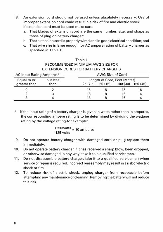
8. An extension cord should not be used unless absolutely necessary. Use ofimproper extension cord could result in a risk of fire and electric shock.If extension cord must be used make sure:a. That blades of extension cord are the same number, size, and shape as
those of plug on battery charger:b. That extension cord is properly wired and in good electrical condition; andc. That wire size is large enough for AC ampere rating of battery charger as
specified in Table 1.
Table 1RECOMMENDED MINIMUM AWG SIZE FOR
EXTENSION CORDS FOR BATTERY CHARGERS
AC Input Rating Amperes* AWG Size of Cord
Equal to or but less Length of Cord, Feet (Meter)greater than than 25 (7.5) 50 (15) 100 (30) 150 (45)
0 2 18 18 18 162 3 18 18 16 143 4 18 18 16 14
* If the input rating of a battery charger is given in watts rather than in amperes,the corresponding ampere rating is to be determined by dividing the wattagerating by the voltage rating-for example:
9. Do not operate battery charger with damaged cord or plug-replace themimmediately.
10. Do not operate battery charger if it has received a sharp blow, been dropped,or otherwise damaged in any way; take it to a qualified serviceman.
11. Do not disassemble battery charger; take it to a qualified serviceman whenservice or repair is required. Incorrect reassembly may result in a risk of electricshock or fire.
12. To reduce risk of electric shock, unplug charger from receptacle beforeattempting any maintenance or cleaning. Removing the battery will not reducethis risk.
1250watts 125 volts
= 10 amperes
9
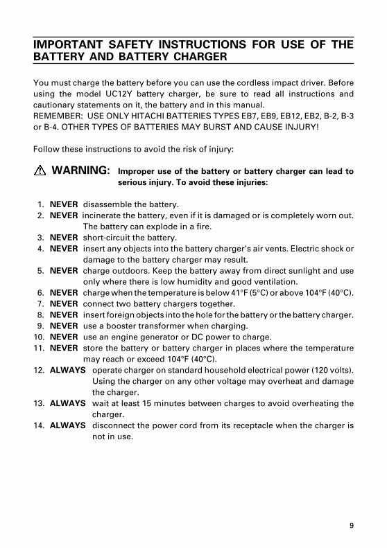
IMPORTANT SAFETY INSTRUCTIONS FOR USE OF THEBATTERY AND BATTERY CHARGER
You must charge the battery before you can use the cordless impact driver. Beforeusing the model UC12Y battery charger, be sure to read all instructions andcautionary statements on it, the battery and in this manual.REMEMBER: USE ONLY HITACHI BATTERIES TYPES EB7, EB9, EB12, EB2, B-2, B-3or B-4. OTHER TYPES OF BATTERIES MAY BURST AND CAUSE INJURY!
Follow these instructions to avoid the risk of injury:
WARNING: Improper use of the battery or battery charger can lead to
serious injury. To avoid these injuries:
1. NEVER disassemble the battery.2. NEVER incinerate the battery, even if it is damaged or is completely worn out.
The battery can explode in a fire.3. NEVER short-circuit the battery.4. NEVER insert any objects into the battery charger’s air vents. Electric shock or
damage to the battery charger may result.5. NEVER charge outdoors. Keep the battery away from direct sunlight and use
only where there is low humidity and good ventilation.6. NEVER charge when the temperature is below 41°F (5°C) or above 104°F (40°C).7. NEVER connect two battery chargers together.8. NEVER insert foreign objects into the hole for the battery or the battery charger.9. NEVER use a booster transformer when charging.
10. NEVER use an engine generator or DC power to charge.11. NEVER store the battery or battery charger in places where the temperature
may reach or exceed 104°F (40°C).12. ALWAYS operate charger on standard household electrical power (120 volts).
Using the charger on any other voltage may overheat and damagethe charger.
13. ALWAYS wait at least 15 minutes between charges to avoid overheating thecharger.
14. ALWAYS disconnect the power cord from its receptacle when the charger isnot in use.
10
DISPOSAL OF THE EXHAUSTED BATTERY
WARNING: Do not dispose of the exhausted battery. The battery must
explode if it is incinerated. The product that you have pur-
chased contains a rechargeable battery. The battery is recy-
clable. At the end of it’s useful life, under various state and
local laws, it may be illegal to dispose of this battery into the
municipal waste stream. Check with your local solid waste
officials for details in your area for recycling options or proper
disposal.
SAVE THESE INSTRUCTIONSAND
MAKE THEM AVAILABLE TOOTHER USERS OF THIS TOOL!
11
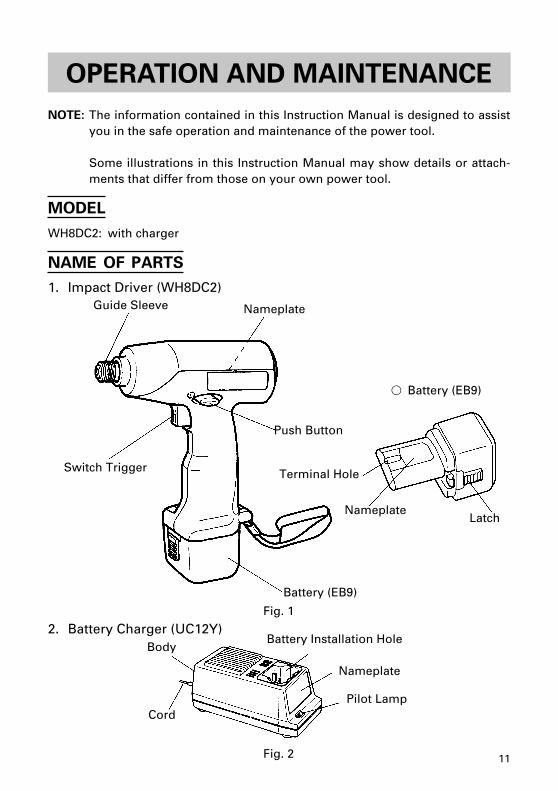
OPERATION AND MAINTENANCE
NOTE: The information contained in this Instruction Manual is designed to assistyou in the safe operation and maintenance of the power tool.
Some illustrations in this Instruction Manual may show details or attach-ments that differ from those on your own power tool.
MODEL
WH8DC2: with charger
NAME OF PARTS
1. Impact Driver (WH8DC2)
2. Battery Charger (UC12Y)Body
CordPilot Lamp
Nameplate
Battery Installation Hole
Nameplate
Battery (EB9)
Guide Sleeve
Switch Trigger
Push Button
Terminal Hole
NameplateLatch
� Battery (EB9)
Fig. 1
Fig. 2
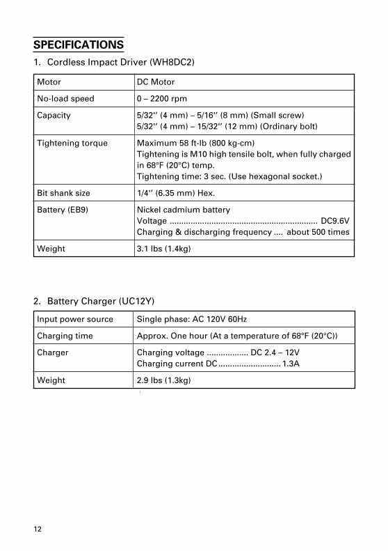
12
Motor DC Motor
No-load speed 0 – 2200 rpm
Capacity 5/32'’ (4 mm) – 5/16'’ (8 mm) (Small screw)5/32'’ (4 mm) – 15/32'’ (12 mm) (Ordinary bolt)
Tightening torque Maximum 58 ft-lb (800 kg-cm)Tightening is M10 high tensile bolt, when fully chargedin 68°F (20°C) temp.Tightening time: 3 sec. (Use hexagonal socket.)
Bit shank size 1/4'’ (6.35 mm) Hex.
Battery (EB9) Nickel cadmium batteryVoltage ................................................................ DC9.6VCharging & discharging frequency .... about 500 times
Weight 3.1 Ibs (1.4kg)
SPECIFICATIONS
1. Cordless Impact Driver (WH8DC2)
2. Battery Charger (UC12Y)
Input power source Single phase: AC 120V 60Hz
Charging time Approx. One hour (At a temperature of 68°F (20°C))
Charger Charging voltage .................. DC 2.4 – 12VCharging current DC........................... 1.3A
Weight 2.9 Ibs (1.3kg)
13
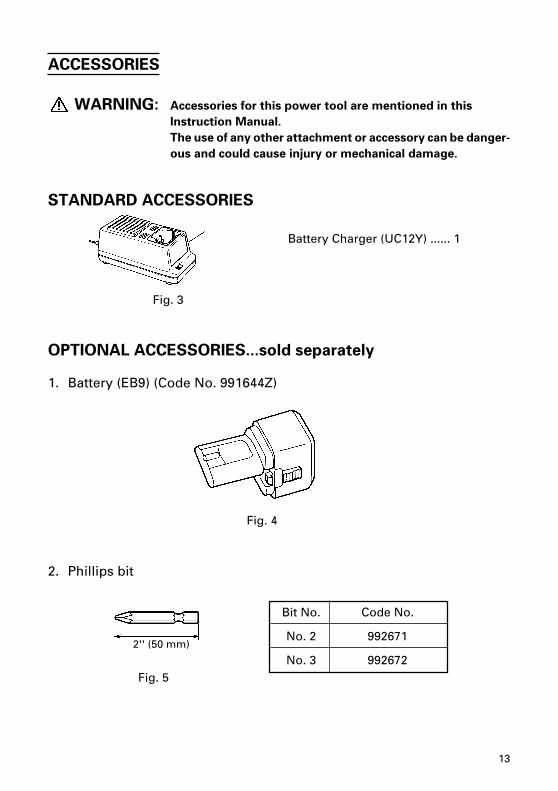
Battery Charger (UC12Y) ...... 1
ACCESSORIES
WARNING: Accessories for this power tool are mentioned in this
Instruction Manual.
The use of any other attachment or accessory can be danger-
ous and could cause injury or mechanical damage.
STANDARD ACCESSORIES
OPTIONAL ACCESSORIES...sold separately
1. Battery (EB9) (Code No. 991644Z)
2. Phillips bit
Fig. 4
Fig. 5
2'' (50 mm)
Fig. 3
Bit No. Code No.
No. 2 992671
No. 3 992672
14
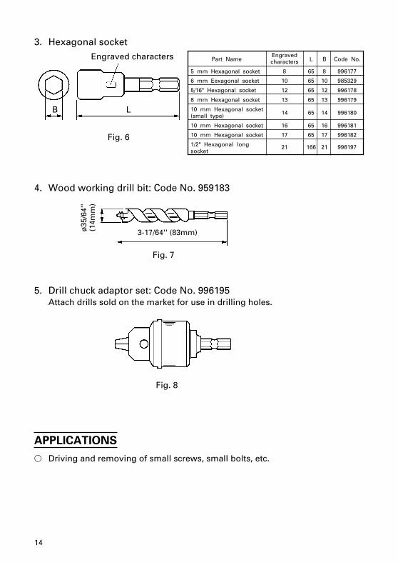
3. Hexagonal socket
4. Wood working drill bit: Code No. 959183
5. Drill chuck adaptor set: Code No. 996195Attach drills sold on the market for use in drilling holes.
APPLICATIONS
� Driving and removing of small screws, small bolts, etc.
Fig. 6
Part NameEngraved
L B Code No.characters
5 mm Hexagonal socket 8 65 8 996177
6 mm Eexagonal socket 10 65 10 985329
5/16" Hexagonal socket 12 65 12 996178
8 mm Hexagonal socket 13 65 13 996179
10 mm Hexagonal socket14 65 14 996180(small type)
10 mm Hexagonal socket 16 65 16 996181
10 mm Hexagonal socket 17 65 17 996182
1/2" Hexagonal longsocket
21 166 21 996197
Fig. 8
Fig. 7
3-17/64'' (83mm)ø35
/64'
'(1
4mm
)
Engraved characters
B L
15
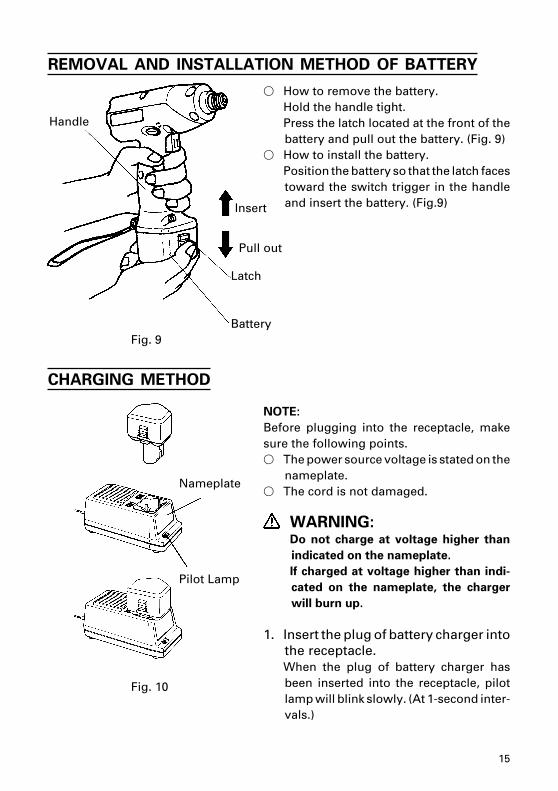
REMOVAL AND INSTALLATION METHOD OF BATTERY
CHARGING METHOD
NOTE:
Before plugging into the receptacle, makesure the following points.� The power source voltage is stated on the
nameplate.� The cord is not damaged.
WARNING:Do not charge at voltage higher than
indicated on the nameplate.
If charged at voltage higher than indi-
cated on the nameplate, the charger
will burn up.
1. Insert the plug of battery charger intothe receptacle.When the plug of battery charger hasbeen inserted into the receptacle, pilotlamp will blink slowly. (At 1-second inter-vals.)
Fig. 10
Fig. 9
Pilot Lamp
Nameplate
� How to remove the battery.Hold the handle tight.Press the latch located at the front of thebattery and pull out the battery. (Fig. 9)
� How to install the battery.Position the battery so that the latch facestoward the switch trigger in the handleand insert the battery. (Fig.9)
Handle
Insert
Pull out
Latch
Battery
16
WARNING: Do not use the electrical cord if damaged.
Have it repaired immediately.
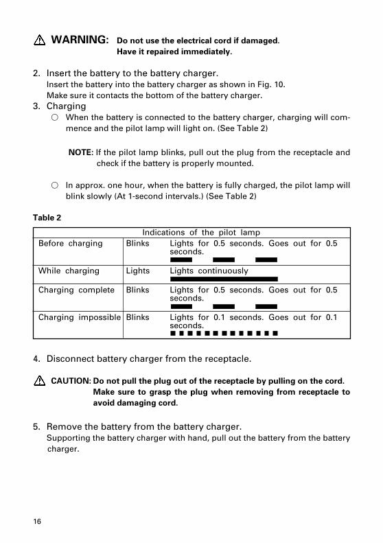
2. Insert the battery to the battery charger.Insert the battery into the battery charger as shown in Fig. 10.Make sure it contacts the bottom of the battery charger.
3. Charging� When the battery is connected to the battery charger, charging will com-
mence and the pilot lamp will light on. (See Table 2)
NOTE: If the pilot lamp blinks, pull out the plug from the receptacle andcheck if the battery is properly mounted.
� In approx. one hour, when the battery is fully charged, the pilot lamp willblink slowly (At 1-second intervals.) (See Table 2)
Table 2
Indications of the pilot lampBefore charging Blinks Lights for 0.5 seconds. Goes out for 0.5
seconds.
While charging Lights Lights continuously
Charging complete Blinks Lights for 0.5 seconds. Goes out for 0.5seconds.
Charging impossible Blinks Lights for 0.1 seconds. Goes out for 0.1seconds.
4. Disconnect battery charger from the receptacle.
CAUTION: Do not pull the plug out of the receptacle by pulling on the cord.
Make sure to grasp the plug when removing from receptacle to
avoid damaging cord.
5. Remove the battery from the battery charger.Supporting the battery charger with hand, pull out the battery from the batterycharger.
17
CAUTION:
� When the battery charger has been continuously used, the battery charger will
be heated, thus constituting the cause of failures. Once the charging has been
completed, give 15 minutes rest until the next charging.
� If the battery is recharged when it is warm due to battery use or exposure to
sunlight, the pilot lamp may not light. The battery will not be recharged. In such
a case, let the battery cool before charging.
� If the pilot lamp blinks quickly (at 0.2-second intervals), check for and take out
any foreign objects in the charger’s battery installation hole.
If there are no foreign objects, it is probable that the battery or charger is
malfunctioning. Bring them to HITACHI AUTHORIZED SERVICE CENTER.
PRIOR TO OPERATION
1. Preparing and checking the work environmentMake sure that the work site meets all the conditions laid forth in the precautions.
2. Checking the batteryMake sure that the battery is installed firmly. If it is at all loose it can fall off andcause an accident.
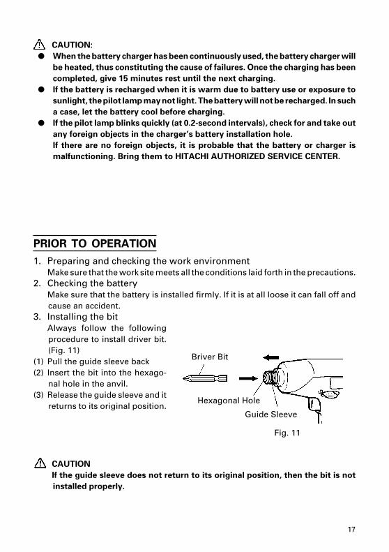
3. Installing the bitAlways follow the followingprocedure to install driver bit.(Fig. 11)
(1) Pull the guide sleeve back(2) Insert the bit into the hexago-
nal hole in the anvil.(3) Release the guide sleeve and it
returns to its original position.
CAUTION
If the guide sleeve does not return to its original position, then the bit is not
installed properly.
Briver Bit
Hexagonal Hole
Guide Sleeve
Fig. 11
18
HOW TO USE
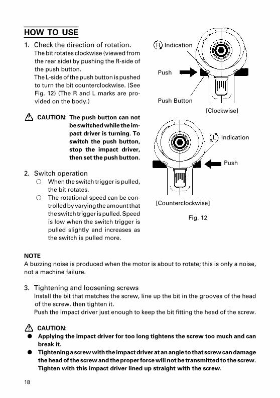
1. Check the direction of rotation.The bit rotates clockwise (viewed fromthe rear side) by pushing the R-side ofthe push button.The L-side of the push button is pushedto turn the bit counterclockwise. (SeeFig. 12) (The R and L marks are pro-vided on the body.)
CAUTION: The push button can not
be switched while the im-
pact driver is turning. To
switch the push button,
stop the impact driver,
then set the push button.
2. Switch operation� When the switch trigger is pulled,
the bit rotates.� The rotational speed can be con-
trolled by varying the amount thatthe switch trigger is pulled. Speedis low when the switch trigger ispulled slightly and increases asthe switch is pulled more.
Push Button
Push
[Clockwise]
Fig. 12
[Counterclockwise]
Push
NOTE
A buzzing noise is produced when the motor is about to rotate; this is only a noise,not a machine failure.
3. Tightening and loosening screwsInstall the bit that matches the screw, line up the bit in the grooves of the headof the screw, then tighten it.Push the impact driver just enough to keep the bit fitting the head of the screw.
CAUTION:
� Applying the impact driver for too long tightens the screw too much and can
break it.
� Tightening a screw with the impact driver at an angle to that screw can damage
the head of the screw and the proper force will not be transmitted to the screw.
Tighten with this impact driver lined up straight with the screw.
Indication
Indication
19
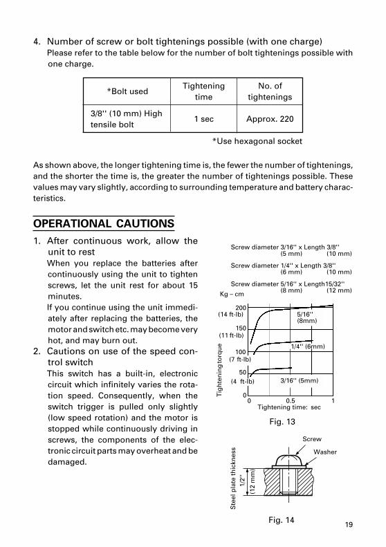
4. Number of screw or bolt tightenings possible (with one charge)Please refer to the table below for the number of bolt tightenings possible withone charge.
*Bolt usedTightening No. of
time tightenings
3/8'' (10 mm) High1 sec Approx. 220
tensile bolt
*Use hexagonal socket
As shown above, the longer tightening time is, the fewer the number of tightenings,and the shorter the time is, the greater the number of tightenings possible. Thesevalues may vary slightly, according to surrounding temperature and battery charac-teristics.
OPERATIONAL CAUTIONS
1. After continuous work, allow theunit to restWhen you replace the batteries aftercontinuously using the unit to tightenscrews, let the unit rest for about 15minutes.If you continue using the unit immedi-ately after replacing the batteries, themotor and switch etc. may become veryhot, and may burn out.
2. Cautions on use of the speed con-trol switchThis switch has a built-in, electroniccircuit which infinitely varies the rota-tion speed. Consequently, when theswitch trigger is pulled only slightly(low speed rotation) and the motor isstopped while continuously driving inscrews, the components of the elec-tronic circuit parts may overheat and bedamaged.
Screw diameter 3/16'' x Length 3/8''(5 mm) (10 mm)
Screw diameter 1/4'' x Length 3/8''(6 mm) (10 mm)
Screw diameter 5/16'' x Length15/32''(8 mm) (12 mm)
(7 ft-lb)
Ste
el p
late
th
ickn
ess
Fig. 14
Screw
Washer
Tightening time: sec
Fig. 13
5/16''(8mm)
3/16'' (5mm)
(11 ft-lb)
Tig
hte
nin
g to
rqu
e
Kg – cm
1/4'' (6mm)
(12
mm
)
1/2'
'
(14 ft-lb)
(4 ft-lb)
200
150
100
50
00 0.5 1
20
3. Tightening torqueRefer to Fig. 13 for the tightening torque of screws (according to size), under theconditions shown in Fig. 14. Please use this example as a general reference, astightening torque will vary according to tightening conditions.
NOTE
� If a long striking time is used, screws will be strongly tightened. This may causethe screw to break, or may damage the end of the bit.
� If the unit is held at an angle to the screw being tightened, the head of the screwmay be damaged, or the specified torque may not be transmitted to the screw.Always keep the unit and the screw being tightened in a straight line.
4. Use a tightening time suitable for the screwThe appropriate torque for a screw differs according to the material and size ofthe screw, and the material being screwed etc., so please use a tightening timesuitable for the screw. In particular, if a long tightening time is used in the caseof screws smaller than 1/4'’ (6 mm), there is a danger of the screw breaking, soplease confirm the tightening time and the tightening torque beforehand.
MAINTENANCE AND INSPECTION
CAUTION: Pull out battery before doing any inspection or maintenance.
1. Checking the condition of the bit.The bits should be checked regularly. If worn or broken bits can slip or decreasethe efficiency of the motor and burn it out.
CAUTION: If you use a driver bit of which point is worn or broken, it will be
dangerous since it slips. So replace it with a new one.
2 Check the Mounting ScrewsLoose mounting screws are dangerous. Regularly inspect them and make surethey are tight.
CAUTION: Using this power tool with loosen, screws is extremely dangerous.
3 Check for DustDust may be removed with a soft cloth or a cloth dampened with soapy water.Do not use bleach, chlorine, gasoline or thinner, for they may damage theplastics.

21
STORAGE
Storing in a place below 104°F (40°C) and out of the reach of children.
SERVICE AND REPAIRS
All quality power tools will eventually require servicing or replacement of partsbecause of wear from normal use. To assure that only authorized replacement partswill be used, all service and repairs must be performed by a HITACHI AUTHORIZEDSERVICE CENTER, ONLY.
NOTE:
Specifications are subject to change without any obligation on the part of theHITACHI.
22
23
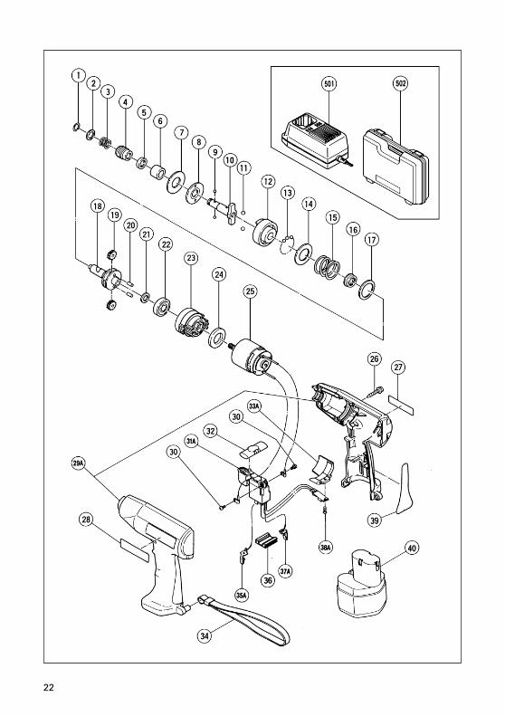
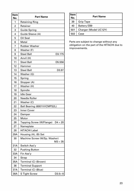
ItemPart Name
No.
1 Retaining Ring
2 Retainer
3 Guide Spring
4 Guide Sleeve (A)
5 Oil Seal
6 Metal
7 Rubber Washer
8 Washer (F)
9 Steel Ball D3.175
10 Anvil (H)
11 Steel Ball D5.556
12 Hammer
13 Steel Ball D3.97
14 Washer (G)
15 Spring
16 Stopper (A)
17 Washer (H)
18 Spindle
19 Idle Gear
20 Needle Roller
21 Washer (C)
22 Ball Bearing (6001VVCMPS2L)
23 Inner Cover
24 Damper
25 Motor
26 Tapping Screw (W/Flange) D4 × 20
27 Nameplate
28 HITACHI Label
29A Housing (A), (B) Set
30 Machine Screw (W/Sp. Washer)M3 × 35
31A Switch Ass’y
32 Pushing Button
33A Fin Ass'y
34 Strap
35A Terminal (C) (Brown)
36 Terminal Support
37A Terminal (C) (Blue)
38A S Tight Screw D3.5× 6
ItemPart Name
No.
39 Grip Tape
40 Battery EB9
501 Charger (Model UC12Y)
502 Case
Parts are subject to change without anyobligation on the part of the HITACHI due toimprovements.
24
Sinagawa Intercity Tower A, 15-1, Konan 2-chome
Minato-ku, Tokyo 108-6020, Japan912
Code No. C99065462 NPrinted in Japan
Please contact HITACHI KOKI U.S.A.LTD. at 1-800-59-TOOLS (toll free), orHITACHI AUTHORIZED POWER TOOLSERVICE CENTER regarding COLLEC-TION.
NICKEL-CADMIUMBATTERY MUST BE RE-CYCLED ORDISPOSED OFPROPERLY.


![À } o © ] } } v Ì ] v · Bb7 Bb7 Db7 Db7 Eb7 Gm7 Db7 * D.C. al Fine Fine (third time) Db 13 Plav through entire form 3 ti mes. Db7 Eb7 F#m7](https://img.pdfslide.us/doc/110x75/5fbec29cae3b4c7bca046993/-o-v-oe-v-bb7-bb7-db7-db7-eb7-gm7-db7-dc-al-fine-fine-third.jpg)