Embed Size (px)
Citation preview

Instruction Manual andExperiment Guide forthe PASCO scientificModel CI-6538
012-06053A5/96
ROTARY MOTION SENSOR
© 1996 PASCO scientific $10.00

012-06053A Rotary Motion Sensor
®i
Table of Contents
Section Page
Copyright Warranty, and Equipment Return................................................... ii
Introduction ..................................................................................................... 1
Optional Accessories
Mini-Rotational Accessory ............................................................................ 2
Linear Motion Accessory .............................................................................. 3
Chaos Accessory ........................................................................................... 3
“A”-Base Rotational Adapter ........................................................................ 4
RMS/Gyroscope Mounting Bracket .............................................................. 5
IDS Mount Accessory ................................................................................... 5
3-step Pulley Accessory ................................................................................ 5
General Setup and Operation
Mounting the RMS ........................................................................................ 6
Plugging the RMS into the Interface ............................................................. 7
Using Science Workshop with the RMS........................................................ 7
Experiments:
Experiment 1: Rotational Inertia of a Point Mass ......................................... 9
Experiment 2: Rotational Inertia of Disk and Ring ...................................... 15
Experiment 3: Conservation of Angular Momentum ................................... 21
Suggested Experiments:
Experiment 4: Force vs. Displacement ......................................................... 25
Experiment 5: Acceleration of Cart with Massive Pulley ............................ 26
Experiment 6: Tension vs. Angle ................................................................. 27
Experiment 7: Conservation of Angular Momentum - Colliding Disks ...... 28
Experiment 8: Simple Harmonic Motion ..................................................... 29
Experiment 9: Damped Pendulum................................................................ 30
Experiment 10: Coupled Pendula ................................................................. 31
Experiment 11: Chaos .................................................................................. 32
Experiment 12: Gyroscope Precession and Nutation ................................... 33
Experiment 13: Buoyant Force vs. Height Submerged ................................ 34
Experiment 14: Pressure vs. Depth in a Fluid .............................................. 35
Experiment 15: Ideal Gas Law ..................................................................... 36
Experiment 16: Magnetic Field vs. Distance ............................................... 37
Experiment 17: Induced Voltage vs. Position of Coil and Magnet .............. 38
Experiment 18: Velocity of Pendula Swinging thru Magnet ....................... 39
Experiment 19: Light Intensity vs. Distance ................................................ 40
Technical Support ...................................................................................Back Cover
Rotary Motion Sensor 012-06053A
®
Please—Feel free to duplicate this manualsubject to the copyright restrictions below.
Copyright, Warranty and Equipment Return
Copyright Notice
The PASCO scientific CI-6538 Rotary Motion Sensormanual is copyrighted and all rights reserved. How-ever, permission is granted to non-profit educationalinstitutions for reproduction of any part of this manualproviding the reproductions are used only for theirlaboratories and are not sold for profit. Reproductionunder any other circumstances, without the writtenconsent of PASCO scientific, is prohibited.
Limited Warranty
PASCO scientific warrants this product to be freefrom defects in materials and workmanship for aperiod of one year from the date of shipment to thecustomer. PASCO will repair or replace, at its option,any part of the product which is deemed to be defec-tive in material or workmanship. This warranty doesnot cover damage to the product caused by abuse orimproper use. Determination of whether a productfailure is the result of a manufacturing defect orimproper use by the customer shall be made solely byPASCO scientific. Responsibility for the return ofequipment for warranty repair belongs to the cus-tomer. Equipment must be properly packed to preventdamage and shipped postage or freight prepaid.(Damage caused by improper packing of the equip-ment for return shipment will not be covered by thewarranty.) Shipping costs for returning the equip-ment, after repair, will be paid by PASCO scientific.
ii
Credits
This manual authored by: Jon Hanks
Equipment Return
Should the product have to be returned to PASCOscientific for any reason, notify PASCO scientific byletter, phone, or fax BEFORE returning the product.Upon notification, the return authorization andshipping instructions will be promptly issued.
When returning equipment for repair, the unitsmust be packed properly. Carriers will not acceptresponsibility for damage caused by improperpacking. To be certain the unit will not bedamaged in shipment, observe the following rules:
➀ The packing carton must be strong enough for theitem shipped.
➁ Make certain there are at least two inches ofpacking material between any point on theapparatus and the inside walls of the carton.
➂ Make certain that the packing material cannot shiftin the box or become compressed, allowing theinstrument come in contact with the packingcarton.
Address: PASCO scientific10101 Foothills Blvd.Roseville, CA 95747-7100
Phone: (916) 786-3800FAX: (916) 786-3292email: [email protected]: www.pasco.com
ä NOTE: NO EQUIPMENT WILL BEACCEPTED FOR RETURN WITHOUT ANAUTHORIZATION FROM PASCO.
012-06053A Rotary Motion Sensor
1®
Introduction
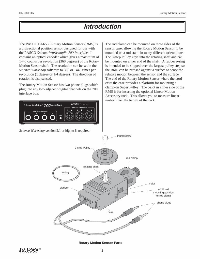
The PASCO CI-6538 Rotary Motion Sensor (RMS) isa bidirectional position sensor designed for use withthe PASCO Science Workshop™ 700 Interface. Itcontains an optical encoder which gives a maximum of1440 counts per revolution (360 degrees) of the RotaryMotion Sensor shaft. The resolution can be set in theScience Workshop software to 360 or 1440 times perrevolution (1 degree or 1/4 degree). The direction ofrotation is also sensed.
The Rotary Motion Sensor has two phone plugs whichplug into any two adjacent digital channels on the 700interface box.
DIGITAL CHANNELS
1 2 3 4ON
A ▲ B ■ C
ANALOG CHANNELS700 InterfaceScience Workshop™
Science Workshop version 2.1 or higher is required.
The rod clamp can be mounted on three sides of thesensor case, allowing the Rotary Motion Sensor to bemounted on a rod stand in many different orientations.The 3-step Pulley keys into the rotating shaft and canbe mounted on either end of the shaft. A rubber o-ringis intended to be slipped over the largest pulley step sothe RMS can be pressed against a surface to sense therelative motion between the sensor and the surface.The end of the Rotary Motion Sensor where the cordexits the case provides a platform for mounting aclamp-on Super Pulley. The t-slot in either side of theRMS is for inserting the optional Linear MotionAccessory rack. This allows you to measure linearmotion over the length of the rack.
Rotary Motion Sensor Parts
phone plugs
rod clamp
platform
o-ring
rotating shaft
3-step Pulley
thumbscrew
case
t-slot
additionalmounting position
for rod clamp
Rotary Motion Sensor 012-06053A
2 ®
Optional Accessories
Mini-Rotational Accessory
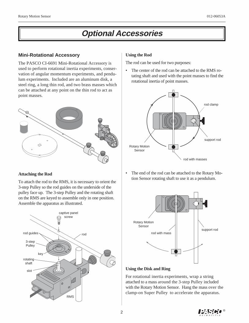
The PASCO CI-6691 Mini-Rotational Accessory isused to perform rotational inertia experiments, conser-vation of angular momentum experiments, and pendu-lum experiments. Included are an aluminum disk, asteel ring, a long thin rod, and two brass masses whichcan be attached at any point on the thin rod to act aspoint masses.
Attaching the Rod
To attach the rod to the RMS, it is necessary to orient the3-step Pulley so the rod guides on the underside of thepulley face up. The 3-step Pulley and the rotating shafton the RMS are keyed to assemble only in one position.Assemble the apparatus as illustrated.
Using the Rod
The rod can be used for two purposes:
• The center of the rod can be attached to the RMS ro-tating shaft and used with the point masses to find therotational inertia of point masses.
Using the Disk and Ring
For rotational inertia experiments, wrap a stringattached to a mass around the 3-step Pulley includedwith the Rotary Motion Sensor. Hang the mass over theclamp-on Super Pulley to accelerate the apparatus.
Rotary MotionSensor
support rod
rod with masses
rod clamp
• The end of the rod can be attached to the Rotary Mo-tion Sensor rotating shaft to use it as a pendulum.
Rotary MotionSensor
rod with masssupport rod
rodrod guides
key
3-stepPulley
slot
RMS
captive panelscrew
rotatingshaft
012-06053A Rotary Motion Sensor
3®
ring
clamp-onSuper Pulley
RMS with3-step Pulley
disk
rod clamp
string
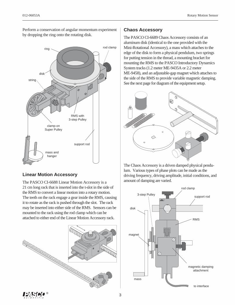
Perform a conservation of angular momentum experimentby dropping the ring onto the rotating disk.
Chaos Accessory
The PASCO CI-6689 Chaos Accessory consists of analuminum disk (identical to the one provided with theMini-Rotational Accessory), a mass which attaches to theedge of the disk to form a physical pendulum, two springsfor putting tension in the thread, a mounting bracket formounting the RMS to the PASCO Introductory DynamicsSystem tracks (1.2 meter ME-9435A or 2.2 meterME-9458), and an adjustable-gap magnet which attaches tothe side of the RMS to provide variable magnetic damping.See the next page for diagram of the equipment setup.
Linear Motion Accessory
The PASCO CI-6688 Linear Motion Accessory is a21 cm long rack that is inserted into the t-slot in the side ofthe RMS to convert a linear motion into a rotary motion.The teeth on the rack engage a gear inside the RMS, causingit to rotate as the rack is pushed through the slot. The rackmay be inserted into either side of the RMS. Sensors can bemounted to the rack using the rod clamp which can beattached to either end of the Linear Motion Accessory rack.
mass andhanger
support rod
magnetic dampingattachment
disk
3-step Pulley
RMS
support rod
rod clamp
mass
magnet
to interface
The Chaos Accessory is a driven damped physical pendu-lum. Various types of phase plots can be made as thedriving frequency, driving amplitude, initial conditions, andamount of damping are varied.
Rotary Motion Sensor 012-06053A
4 ®
Mechanical Oscillator/Driver
AdjustableEnd-Stop
spring (2)
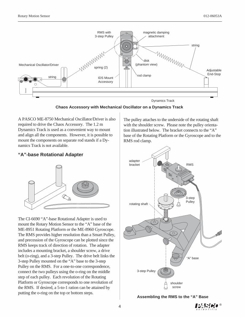
Chaos Accessory with Mechanical Oscillator on a Dynamics Track
string
string
magnetic dampingattachment
RMS with3-step Pulley
rod clamp
disk(phantom view)
IDS MountAccessory
Dynamics Track
A PASCO ME-8750 Mechanical Oscillator/Driver is alsorequired to drive the Chaos Accessory. The 1.2 mDynamics Track is used as a convenient way to mountand align all the components. However, it is possible tomount the components on separate rod stands if a Dy-namics Track is not available.
“A”-base Rotational Adapter
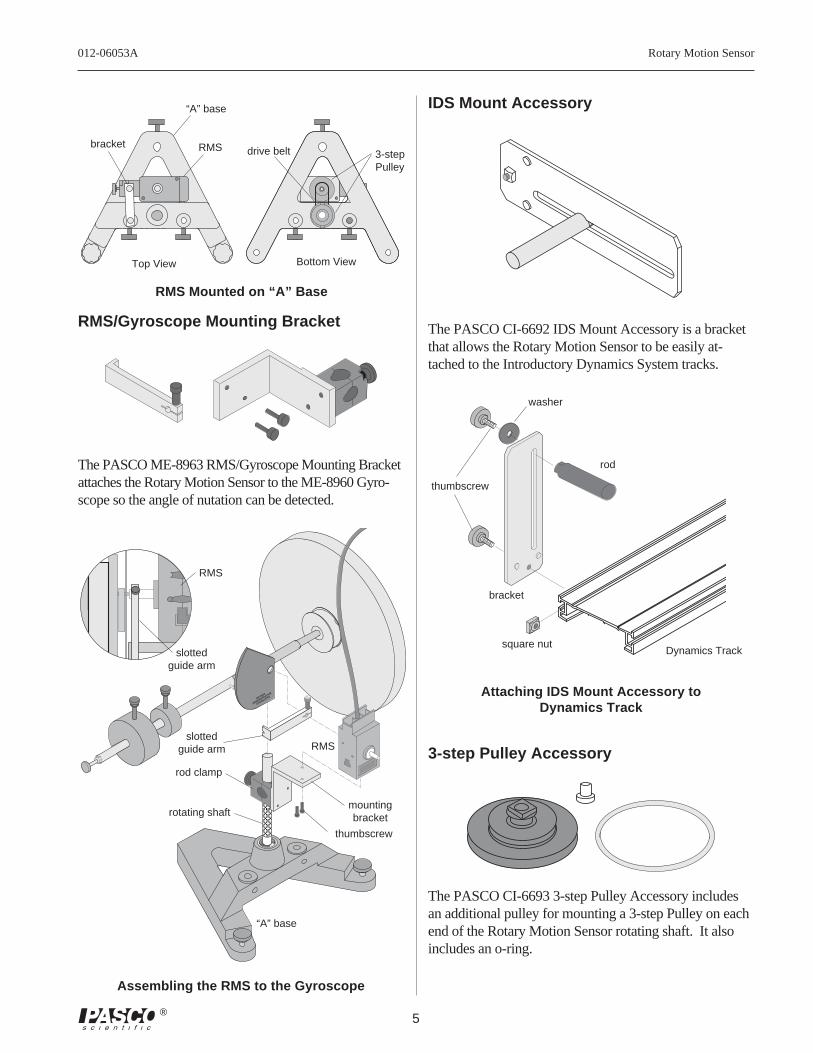
The CI-6690 “A”-base Rotational Adapter is used tomount the Rotary Motion Sensor to the “A” base of theME-8951 Rotating Platform or the ME-8960 Gyroscope.The RMS provides higher resolution than a Smart Pulley,and precession of the Gyroscope can be plotted since theRMS keeps track of direction of rotation. The adapterincludes a mounting bracket, a shoulder screw, a drivebelt (o-ring), and a 3-step Pulley. The drive belt links the3-step Pulley mounted on the “A” base to the 3-stepPulley on the RMS. For a one-to-one correspondence,connect the two pulleys using the o-ring on the middlestep of each pulley. Each revolution of the RotatingPlatform or Gyroscope corresponds to one revolution ofthe RMS. If desired, a 5-to-1 ration can be attained byputting the o-ring on the top or bottom steps.
RMS
3-stepPulley
rotating shaft
“A” base
3-step Pulley
shoulderscrew
adapterbracket
Assembling the RMS to the “A” Base
The pulley attaches to the underside of the rotating shaftwith the shoulder screw. Please note the pulley orienta-tion illustrated below. The bracket connects to the “A”base of the Rotating Platform or the Gyroscope and to theRMS rod clamp.
012-06053A Rotary Motion Sensor
5®
Top View Bottom View
3-stepPulley
drive beltRMSbracket
“A” base
RMS Mounted on “A” Base
IDS Mount Accessory
The PASCO CI-6692 IDS Mount Accessory is a bracketthat allows the Rotary Motion Sensor to be easily at-tached to the Introductory Dynamics System tracks.
Dynamics Track
thumbscrew
rod
square nut
bracket
washer
Attaching IDS Mount Accessory toDynamics Track
3-step Pulley Accessory
The PASCO CI-6693 3-step Pulley Accessory includesan additional pulley for mounting a 3-step Pulley on eachend of the Rotary Motion Sensor rotating shaft. It alsoincludes an o-ring.
RMS/Gyroscope Mounting Bracket
The PASCO ME-8963 RMS/Gyroscope Mounting Bracketattaches the Rotary Motion Sensor to the ME-8960 Gyro-scope so the angle of nutation can be detected.
ME-8960
DEMONSTRATION
GYROSCOPE
slottedguide arm
mountingbracket
rod clamp
rotating shaft
“A” base
RMS
thumbscrew
RMS
slottedguide arm
Assembling the RMS to the Gyroscope
Rotary Motion Sensor 012-06053A
6 ®
General Setup and Operation
Mounting the RMS
Attaching the RMS to a Support Rod
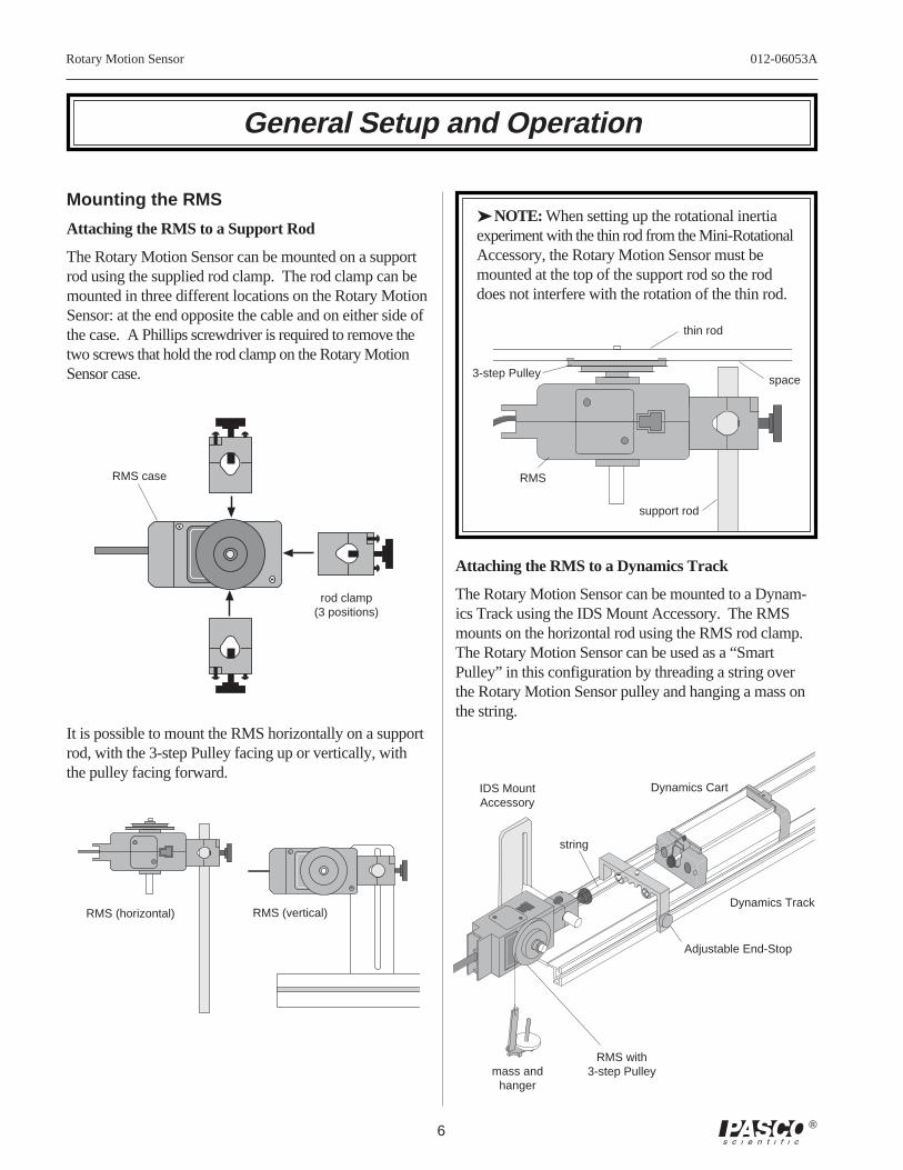
The Rotary Motion Sensor can be mounted on a supportrod using the supplied rod clamp. The rod clamp can bemounted in three different locations on the Rotary MotionSensor: at the end opposite the cable and on either side ofthe case. A Phillips screwdriver is required to remove thetwo screws that hold the rod clamp on the Rotary MotionSensor case.
It is possible to mount the RMS horizontally on a supportrod, with the 3-step Pulley facing up or vertically, withthe pulley facing forward.
space
➤ NOTE: When setting up the rotational inertiaexperiment with the thin rod from the Mini-RotationalAccessory, the Rotary Motion Sensor must bemounted at the top of the support rod so the roddoes not interfere with the rotation of the thin rod.
Attaching the RMS to a Dynamics Track
The Rotary Motion Sensor can be mounted to a Dynam-ics Track using the IDS Mount Accessory. The RMSmounts on the horizontal rod using the RMS rod clamp.The Rotary Motion Sensor can be used as a “SmartPulley” in this configuration by threading a string overthe Rotary Motion Sensor pulley and hanging a mass onthe string.
3-step Pulley
RMS
support rod
Dynamics Cart
Dynamics Track
Adjustable End-Stop
string
IDS MountAccessory
RMS case
rod clamp(3 positions)
RMS (horizontal) RMS (vertical)
mass andhanger
RMS with3-step Pulley
thin rod
012-06053A Rotary Motion Sensor
7®
ME-8960
DEMONSTRATION
GYROSCOPE
Attaching the RMS to the “A” base
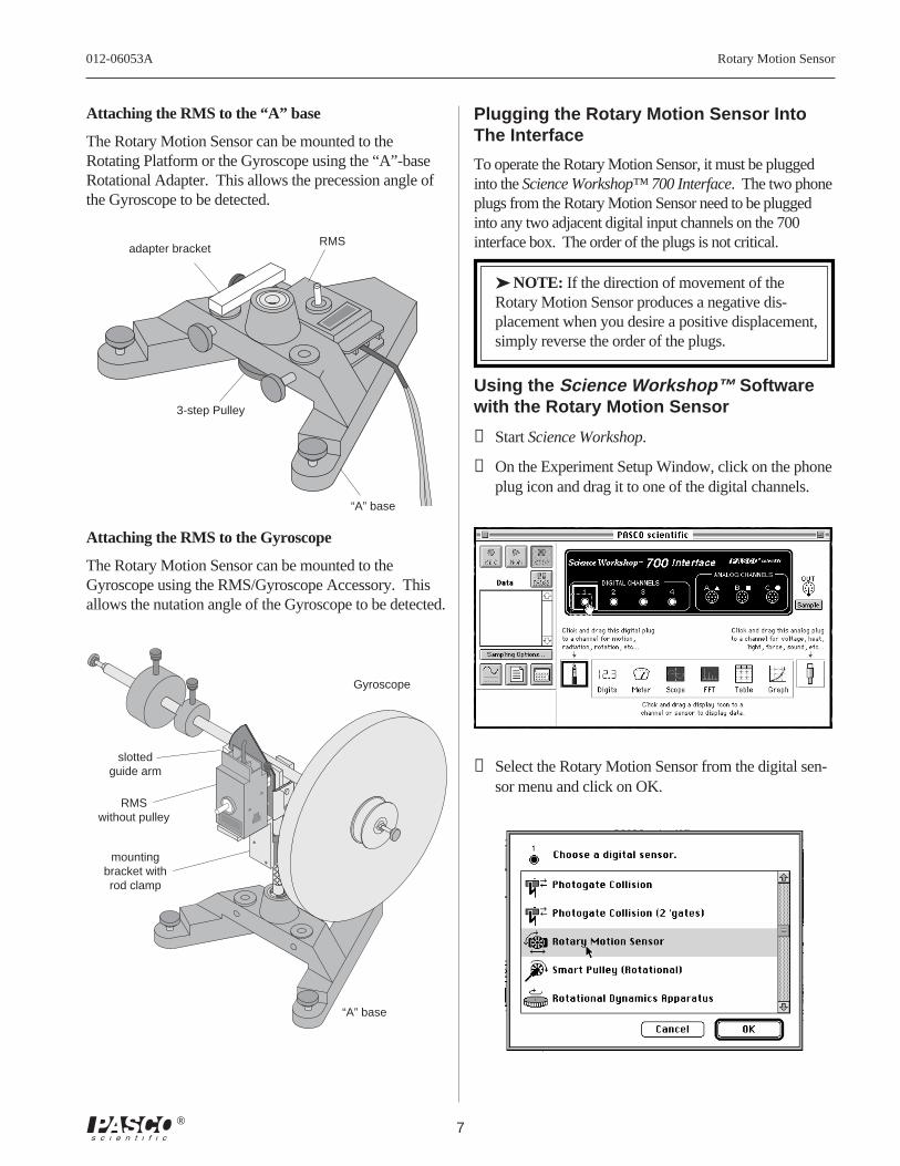
The Rotary Motion Sensor can be mounted to theRotating Platform or the Gyroscope using the “A”-baseRotational Adapter. This allows the precession angle ofthe Gyroscope to be detected.
Plugging the Rotary Motion Sensor IntoThe Interface
To operate the Rotary Motion Sensor, it must be pluggedinto the Science Workshop™ 700 Interface. The two phoneplugs from the Rotary Motion Sensor need to be pluggedinto any two adjacent digital input channels on the 700interface box. The order of the plugs is not critical.
➤ NOTE: If the direction of movement of theRotary Motion Sensor produces a negative dis-placement when you desire a positive displacement,simply reverse the order of the plugs.
Using the Science Workshop™ Softwarewith the Rotary Motion Sensor
➀ Start Science Workshop.
➁ On the Experiment Setup Window, click on the phoneplug icon and drag it to one of the digital channels.
➂ Select the Rotary Motion Sensor from the digital sen-sor menu and click on OK.
adapter bracket
“A” base
3-step Pulley
RMS
Attaching the RMS to the Gyroscope
The Rotary Motion Sensor can be mounted to theGyroscope using the RMS/Gyroscope Accessory. Thisallows the nutation angle of the Gyroscope to be detected.
Gyroscope
“A” base
slottedguide arm
mountingbracket withrod clamp
RMSwithout pulley
Rotary Motion Sensor 012-06053A
8 ®
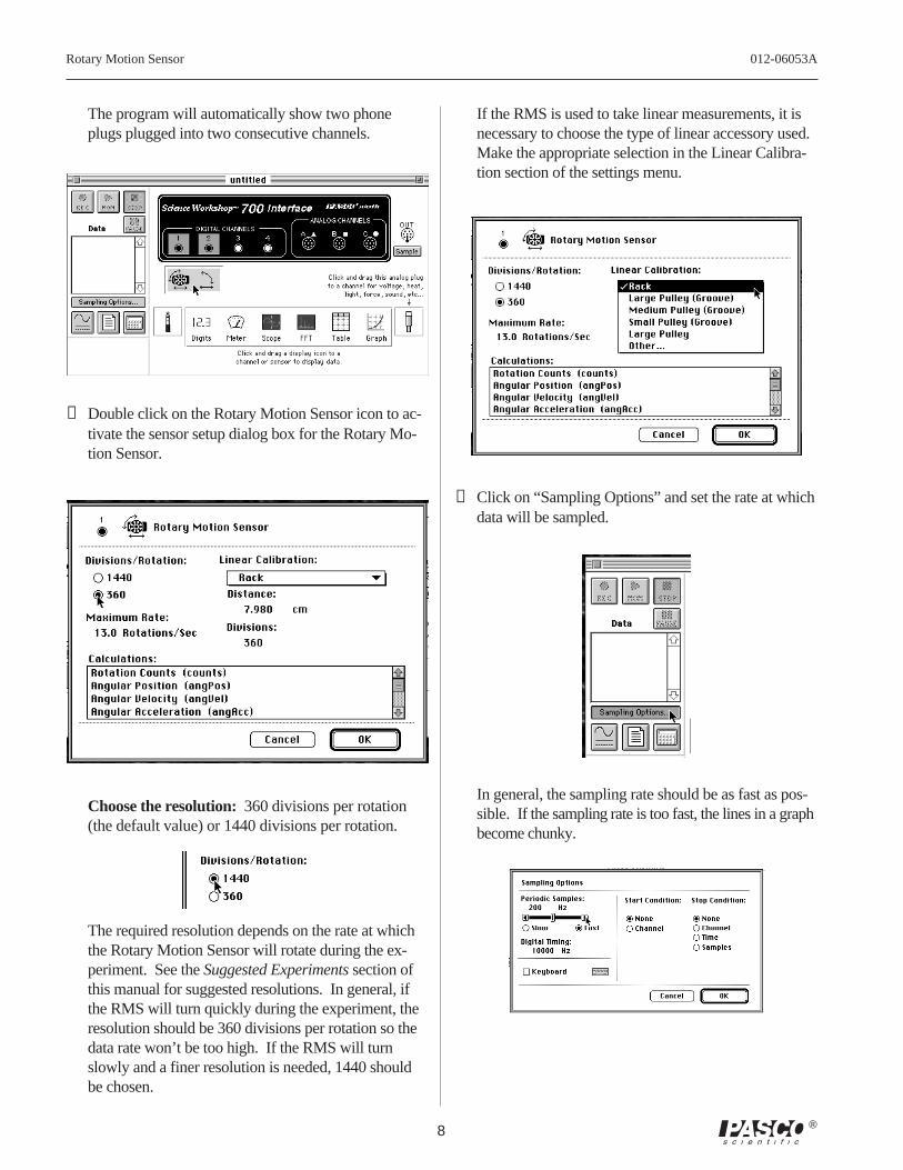
The program will automatically show two phoneplugs plugged into two consecutive channels.
➃ Double click on the Rotary Motion Sensor icon to ac-tivate the sensor setup dialog box for the Rotary Mo-tion Sensor.
Choose the resolution: 360 divisions per rotation(the default value) or 1440 divisions per rotation.
The required resolution depends on the rate at whichthe Rotary Motion Sensor will rotate during the ex-periment. See the Suggested Experiments section ofthis manual for suggested resolutions. In general, ifthe RMS will turn quickly during the experiment, theresolution should be 360 divisions per rotation so thedata rate won’t be too high. If the RMS will turnslowly and a finer resolution is needed, 1440 shouldbe chosen.
If the RMS is used to take linear measurements, it isnecessary to choose the type of linear accessory used.Make the appropriate selection in the Linear Calibra-tion section of the settings menu.
➄ Click on “Sampling Options” and set the rate at whichdata will be sampled.
In general, the sampling rate should be as fast as pos-sible. If the sampling rate is too fast, the lines in a graphbecome chunky.
012-06053A Rotary Motion Sensor
9®
EQUIPMENT REQUIRED
– Science Workshop™ 700 Interface – Rotary Motion Sensor (CI-6538)– Mini-Rotational Accessory (CI-6691) – Mass and Hanger Set (ME-9348)– Base and Support Rod (ME-9355) – Triple Beam Balance (SE-8723)– paper clips (for masses < 1 g) – calipers
Purpose
The purpose of this experiment is to find the rotational inertia of a point mass experimentallyand to verify that this value corresponds to the calculated theoretical value.
Theory
Theoretically, the rotational inertia, I, of a point mass is given by I = MR2, where M is the mass,and R is the distance the mass is from the axis of rotation. Since this experiment uses twomasses equidistant from the center of rotation, the total rotational inertia will be
Itotal = MtotalR2
where Mtotal
= M1 + M
2, the total mass of both point masses.
To find the rotational inertia experimentally, a known torque is applied to the object and theresulting angular acceleration is measured. Since τ = Iα,
I = τα
where α is the angular acceleration, which is equal to a/r (a = linear acceleration), and τ is thetorque caused by the weight hanging from the thread that is wrapped around the 3-step Pulley.
τ = rT
where r is the radius of the chosen pulley about which the thread is wound, and T is the tensionin the thread when the apparatus is rotating.
Applying Newton’s Second Law for the hanging mass, m, gives
Σ F = mg – T = ma
(see Figure 1.1). Solving for the tension in the thread gives:
T = m g – a
Once the angular acceleration of the mass (m) is measured, the torque and the linear accelerationcan be obtained for the calculation of the rotational inertia.
Experiment 1: Rotational Inertia of a Point Mass
Rotary Motion Sensor 012-06053A
10 ®
Setup
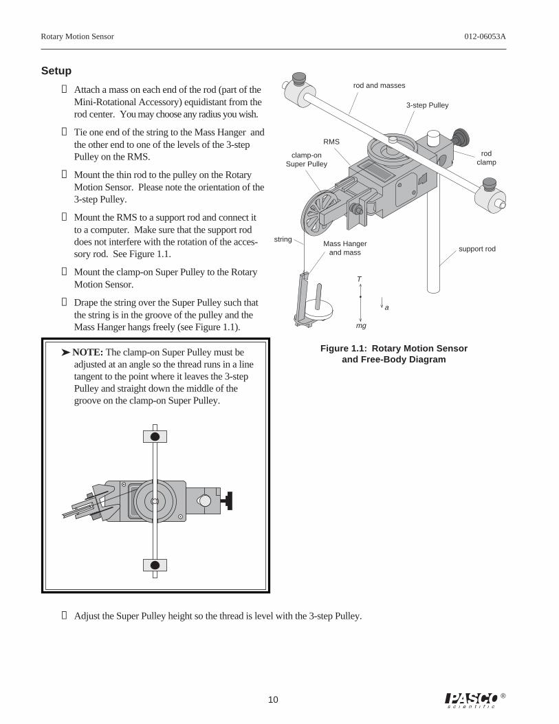
➀ Attach a mass on each end of the rod (part of theMini-Rotational Accessory) equidistant from therod center. You may choose any radius you wish.
➁ Tie one end of the string to the Mass Hanger andthe other end to one of the levels of the 3-stepPulley on the RMS.
➂ Mount the thin rod to the pulley on the RotaryMotion Sensor. Please note the orientation of the3-step Pulley.
➃ Mount the RMS to a support rod and connect itto a computer. Make sure that the support roddoes not interfere with the rotation of the acces-sory rod. See Figure 1.1.
➄ Mount the clamp-on Super Pulley to the RotaryMotion Sensor.
➅ Drape the string over the Super Pulley such thatthe string is in the groove of the pulley and theMass Hanger hangs freely (see Figure 1.1).
➤ NOTE: The clamp-on Super Pulley must beadjusted at an angle so the thread runs in a linetangent to the point where it leaves the 3-stepPulley and straight down the middle of thegroove on the clamp-on Super Pulley.
➆ Adjust the Super Pulley height so the thread is level with the 3-step Pulley.
3-step Pulley
RMS
Figure 1.1: Rotary Motion Sensorand Free-Body Diagram
mg
T
a
clamp-onSuper Pulley
Mass Hangerand mass
stringsupport rod
rod and masses
rodclamp
012-06053A Rotary Motion Sensor
11®
Procedure
Part I: Measurements For the Theoretical Rotational Inertia
➀ Weigh the masses to find the total mass Mtotal
and record in Table 1.1.
➁ Measure the distance from the axis of rotation to the center of the masses and record this radiusin Table 1.1.
Part II: Measurement For the Experimental Method
Finding the Acceleration of the Point Masses and Apparatus
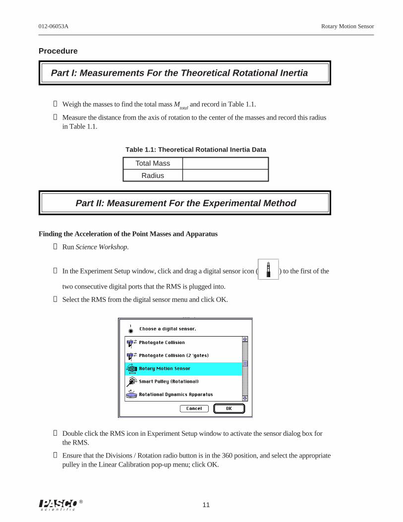
➀ Run Science Workshop.
➁ In the Experiment Setup window, click and drag a digital sensor icon ( ) to the first of the
two consecutive digital ports that the RMS is plugged into.
➂ Select the RMS from the digital sensor menu and click OK.
➃ Double click the RMS icon in Experiment Setup window to activate the sensor dialog box forthe RMS.
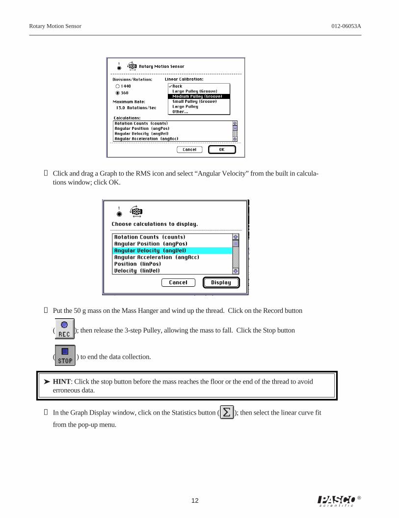
➄ Ensure that the Divisions / Rotation radio button is in the 360 position, and select the appropriatepulley in the Linear Calibration pop-up menu; click OK.
Table 1.1: Theoretical Rotational Inertia Data
Total Mass
Radius
Rotary Motion Sensor 012-06053A
12 ®
➅ Click and drag a Graph to the RMS icon and select “Angular Velocity” from the built in calcula-tions window; click OK.
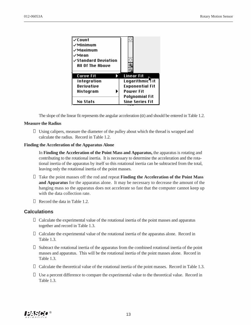
➆ Put the 50 g mass on the Mass Hanger and wind up the thread. Click on the Record button
( ); then release the 3-step Pulley, allowing the mass to fall. Click the Stop button
( ) to end the data collection.
➤ HINT : Click the stop button before the mass reaches the floor or the end of the thread to avoiderroneous data.
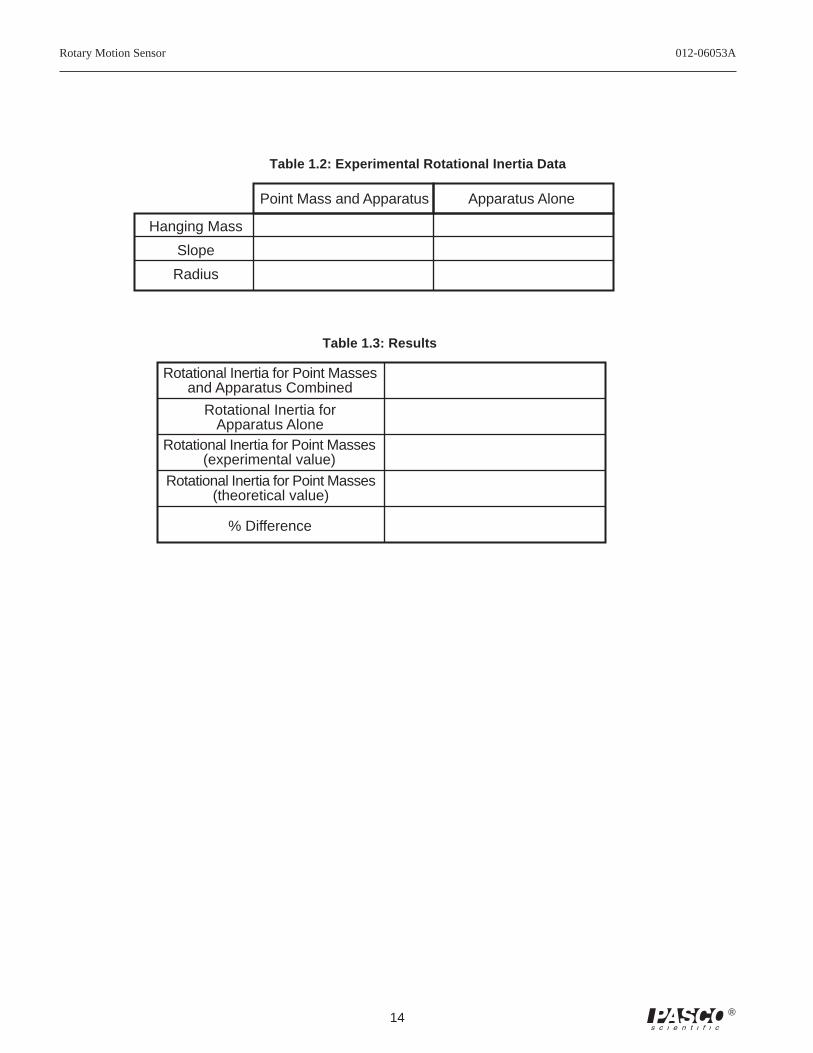
➇ In the Graph Display window, click on the Statistics button ( ); then select the linear curve fit
from the pop-up menu.
012-06053A Rotary Motion Sensor
13®
The slope of the linear fit represents the angular acceleration (α) and should be entered in Table 1.2.
Measure the Radius
➀ Using calipers, measure the diameter of the pulley about which the thread is wrapped andcalculate the radius. Record in Table 1.2.
Finding the Acceleration of the Apparatus Alone
In Finding the Acceleration of the Point Mass and Apparatus, the apparatus is rotating andcontributing to the rotational inertia. It is necessary to determine the acceleration and the rota-tional inertia of the apparatus by itself so this rotational inertia can be subtracted from the total,leaving only the rotational inertia of the point masses.
➀ Take the point masses off the rod and repeat Finding the Acceleration of the Point Massand Apparatus for the apparatus alone. It may be necessary to decrease the amount of thehanging mass so the apparatus does not accelerate so fast that the computer cannot keep upwith the data collection rate.
➁ Record the data in Table 1.2.
Calculations
➀ Calculate the experimental value of the rotational inertia of the point masses and apparatustogether and record in Table 1.3.
➁ Calculate the experimental value of the rotational inertia of the apparatus alone. Record inTable 1.3.
➂ Subtract the rotational inertia of the apparatus from the combined rotational inertia of the pointmasses and apparatus. This will be the rotational inertia of the point masses alone. Record inTable 1.3.
➃ Calculate the theoretical value of the rotational inertia of the point masses. Record in Table 1.3.
➄ Use a percent difference to compare the experimental value to the theoretical value. Record inTable 1.3.
Rotary Motion Sensor 012-06053A
14 ®
Hanging Mass
Slope
Radius
Point Mass and Apparatus Apparatus Alone
Table 1.2: Experimental Rotational Inertia Data
Rotational Inertia for Point Massesand Apparatus Combined
Rotational Inertia forApparatus Alone
Rotational Inertia for Point Masses(experimental value)
Rotational Inertia for Point Masses(theoretical value)
% Difference
Table 1.3: Results
012-06053A Rotary Motion Sensor
15®
Experiment 2: Rotational Inertia of Disk and Ring
EQUIPMENT REQUIRED
– Science Workshop™ 700 Interface – Rotary Motion Sensor (CI-6538)– Mini-Rotational Accessory (CI-6691) – Mass and Hanger Set (ME-9348)– Base and Support Rod (ME-9355) – Triple Beam Balance (SE-8723)– paper clips (for masses < 1 g) – calipers
Purpose
The purpose of this experiment is to find the rotational inertia of a ring and a diskexperimentally and to verify that these values correspond to the calculated theoreti-cal values.
Theory
Theoretically, the rotational inertia, I, of a ring about its center of mass is given by:
I = 12
M R12 + R2
2
where M is the mass of the ring, R1 is the inner radius of the ring, and R
2 is the
outer radius of the ring. See Figure 2.1.
The rotational inertia of a disk about its center of mass is given by:
I = 12
MR2
where M is the mass of the disk and R is the radius of the disk. See Figure 2.2.
To find the rotational inertia experimentally, a known torque is applied to theobject and the resulting angular acceleration is measured. Since τ = Iα,
I = τα
where α is the angular acceleration, which is equal to a/r (a = acceleration), and τ is the torquecaused by the weight hanging from the thread that is wrapped around the base of the apparatus.
τ = rT
where r is the radius of the pulley about which the thread is wound, and T is the tension in thethread when the apparatus is rotating.
Applying Newton’s Second Law for the hanging mass, m, gives
Σ F = mg – T = ma
(see Figure 2.3). Solving for the tension in the thread gives:
T = m g – a
Figure 2.2: Disk aboutcenter of Mass
R
R1 R2
Figure 2.1: Ring
Rotary Motion Sensor 012-06053A
16 ®
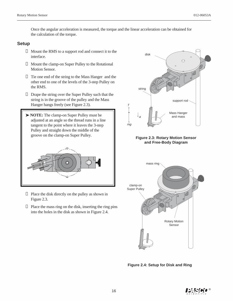
Once the angular acceleration is measured, the torque and the linear acceleration can be obtained forthe calculation of the torque.
Setup
➀ Mount the RMS to a support rod and connect it to theinterface.
➁ Mount the clamp-on Super Pulley to the RotationalMotion Sensor.
➂ Tie one end of the string to the Mass Hanger and theother end to one of the levels of the 3-step Pulley onthe RMS.
➃ Drape the string over the Super Pulley such that thestring is in the groove of the pulley and the MassHanger hangs freely (see Figure 2.3).
➤ NOTE: The clamp-on Super Pulley must beadjusted at an angle so the thread runs in a linetangent to the point where it leaves the 3-stepPulley and straight down the middle of thegroove on the clamp-on Super Pulley.
➄ Place the disk directly on the pulley as shown inFigure 2.3.
➅ Place the mass ring on the disk, inserting the ring pinsinto the holes in the disk as shown in Figure 2.4.
disk
support rod
Mass Hangerand mass
string
mg
T
a
mass ring
clamp-onSuper Pulley
Rotary MotionSensor
Figure 2.4: Setup for Disk and Ring
Figure 2.3: Rotary Motion Sensorand Free-Body Diagram
012-06053A Rotary Motion Sensor
17®
Procedure
Measurements for the Theoretical Rotational Inertia
➀ Weigh the ring and disk to find their masses and record these masses in Table 2.1.
➁ Measure the inside and outside diameters of the ring and calculate the radii, R1 and R
2. Record in
Table 2.1.
➂ Measure the diameter of the disk and calculate the radius, R, and record it in Table 2.1.
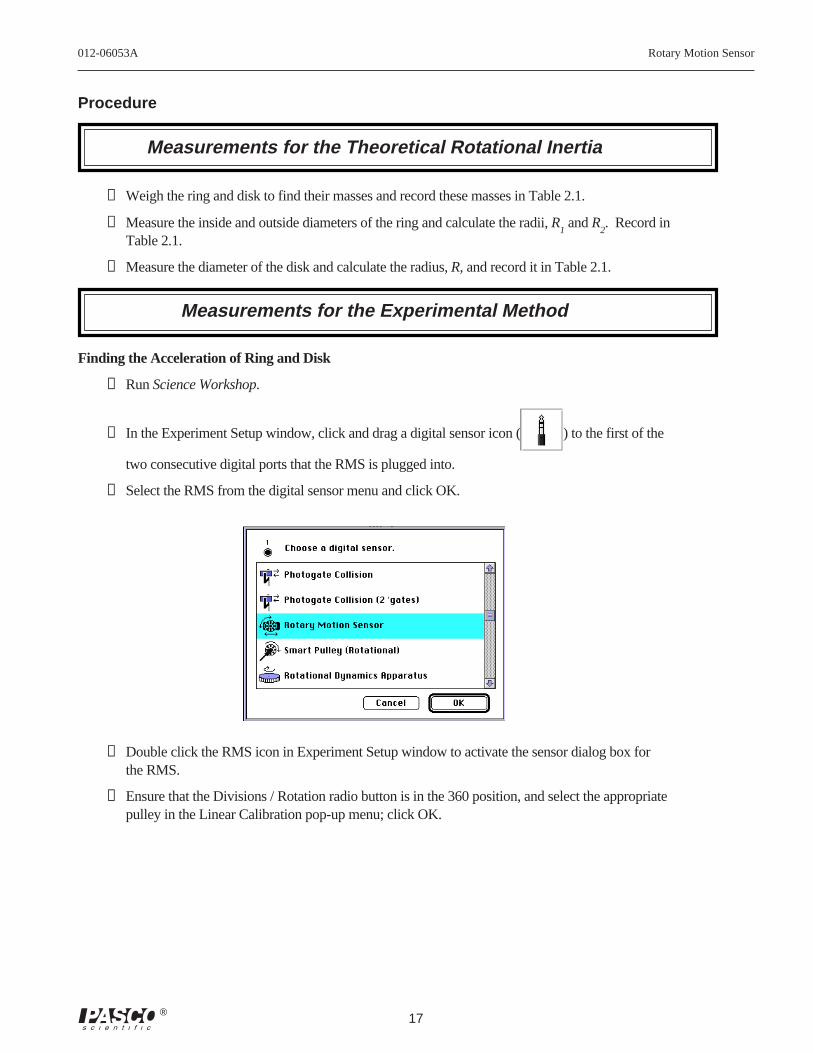
Measurements for the Experimental Method
Finding the Acceleration of Ring and Disk
➀ Run Science Workshop.
➁ In the Experiment Setup window, click and drag a digital sensor icon ( ) to the first of the
two consecutive digital ports that the RMS is plugged into.
➂ Select the RMS from the digital sensor menu and click OK.
➃ Double click the RMS icon in Experiment Setup window to activate the sensor dialog box forthe RMS.
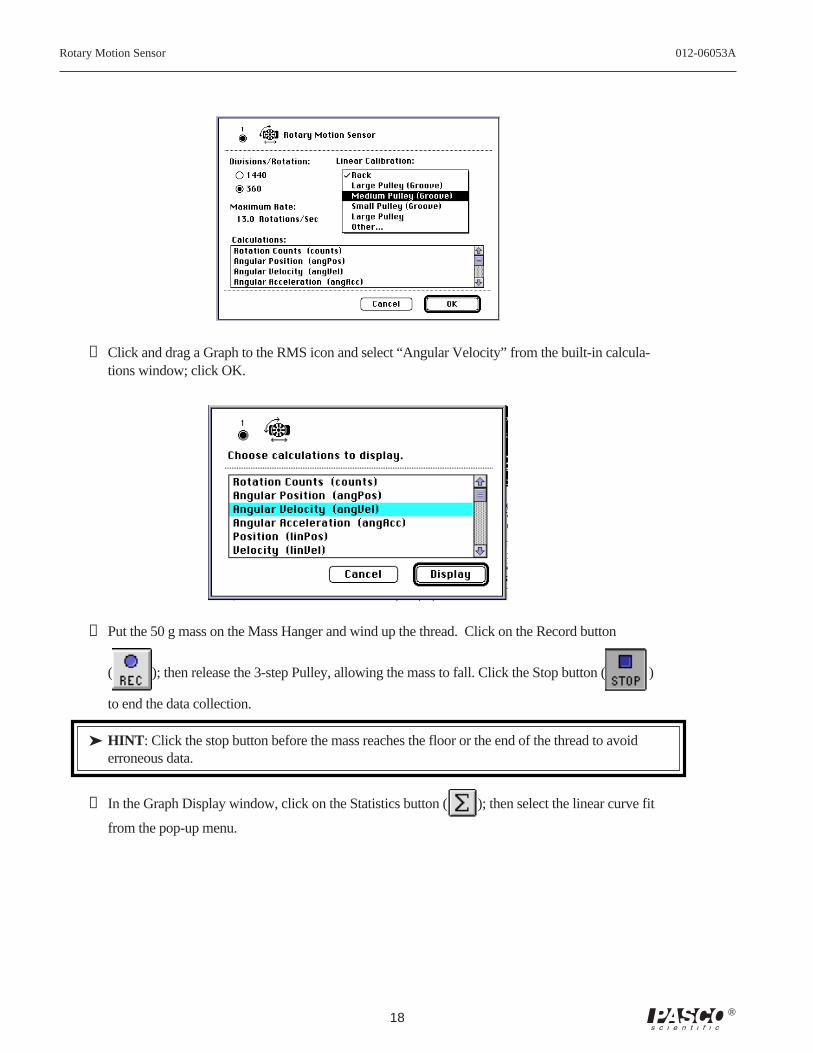
➄ Ensure that the Divisions / Rotation radio button is in the 360 position, and select the appropriatepulley in the Linear Calibration pop-up menu; click OK.
Rotary Motion Sensor 012-06053A
18 ®
➅ Click and drag a Graph to the RMS icon and select “Angular Velocity” from the built-in calcula-tions window; click OK.
➆ Put the 50 g mass on the Mass Hanger and wind up the thread. Click on the Record button
( ); then release the 3-step Pulley, allowing the mass to fall. Click the Stop button ()
to end the data collection.
➤ HINT : Click the stop button before the mass reaches the floor or the end of the thread to avoiderroneous data.
➇ In the Graph Display window, click on the Statistics button ( ); then select the linear curve fit
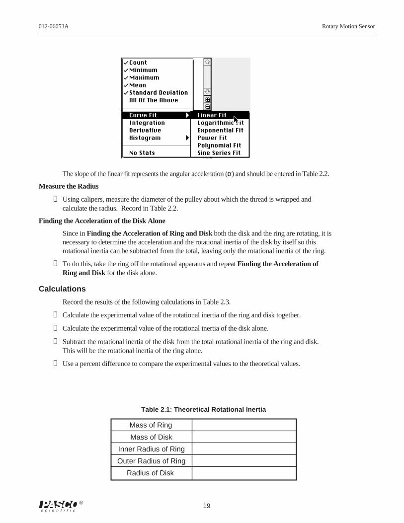
from the pop-up menu.
012-06053A Rotary Motion Sensor
19®
The slope of the linear fit represents the angular acceleration (α) and should be entered in Table 2.2.
Measure the Radius
➀ Using calipers, measure the diameter of the pulley about which the thread is wrapped andcalculate the radius. Record in Table 2.2.
Finding the Acceleration of the Disk Alone
Since in Finding the Acceleration of Ring and Disk both the disk and the ring are rotating, it isnecessary to determine the acceleration and the rotational inertia of the disk by itself so thisrotational inertia can be subtracted from the total, leaving only the rotational inertia of the ring.
➀ To do this, take the ring off the rotational apparatus and repeat Finding the Acceleration ofRing and Disk for the disk alone.
Calculations
Record the results of the following calculations in Table 2.3.
➀ Calculate the experimental value of the rotational inertia of the ring and disk together.
➁ Calculate the experimental value of the rotational inertia of the disk alone.
➂ Subtract the rotational inertia of the disk from the total rotational inertia of the ring and disk.This will be the rotational inertia of the ring alone.
➃ Use a percent difference to compare the experimental values to the theoretical values.
Mass of Ring
Mass of Disk
Inner Radius of Ring
Outer Radius of Ring
Radius of Disk
Table 2.1: Theoretical Rotational Inertia
Rotary Motion Sensor 012-06053A
20 ®
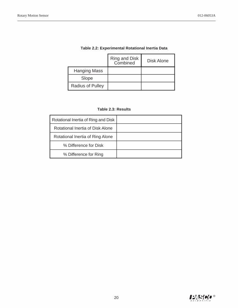
Table 2.3: Results
Rotational Inertia of Ring and Disk
Rotational Inertia of Disk Alone
Rotational Inertia of Ring Alone
% Difference for Disk
% Difference for Ring
Hanging Mass
Slope
Ring and DiskCombined Disk Alone
Radius of Pulley
Table 2.2: Experimental Rotational Inertia Data
012-06053A Rotary Motion Sensor
21®
EQUIPMENT REQUIRED
- Science Workshop™ 700 Interface - Rotary Motion Sensor (CI-6538)- Mini-Rotational Accessory (CI-6691) - Mass and Hanger Set (ME-9348)- Base and Support Rod (ME-9355) - Triple Beam Balance (SE-8723)- paper clips (for masses < 1 g) - calipers
Purpose
A non-rotating ring is dropped onto a rotating disk, and the final angular speed of the system iscompared with the value predicted using conservation of angular momentum.
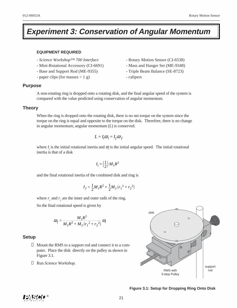
Theory
When the ring is dropped onto the rotating disk, there is no net torque on the system since thetorque on the ring is equal and opposite to the torque on the disk. Therefore, there is no changein angular momentum; angular momentum (L) is conserved.
L = Iiω i = Ifω f
where Ii is the initial rotational inertia and ω
i is the initial angular speed. The initial rotational
inertia is that of a disk
Ii = 12
M1R2
and the final rotational inertia of the combined disk and ring is
I f = 12
M1R2 + 12
M2 r12 + r2
2
where r1 and r
2 are the inner and outer radii of the ring.
So the final rotational speed is given by
ω f =
M1R2
M1R2 + M2 r12 + r2
2ωi
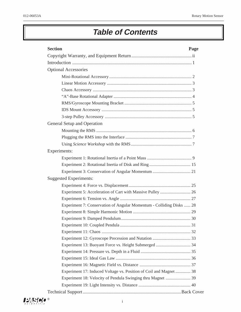
Setup
➀ Mount the RMS to a support rod and connect it to a com-puter. Place the disk directly on the pulley as shown inFigure 3.1.
➁ Run Science Workshop.
Experiment 3: Conservation of Angular Momentum
disk
supportrodRMS with
3-step Pulley
Figure 3.1: Setup for Dropping Ring Onto Disk
Rotary Motion Sensor 012-06053A
22 ®
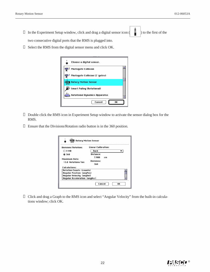
➂ In the Experiment Setup window, click and drag a digital sensor icon ( ) to the first of the
two consecutive digital ports that the RMS is plugged into.
➃ Select the RMS from the digital sensor menu and click OK.
➄ Double click the RMS icon in Experiment Setup window to activate the sensor dialog box for theRMS.
➅ Ensure that the Divisions/Rotation radio button is in the 360 position.
➆ Click and drag a Graph to the RMS icon and select “Angular Velocity” from the built-in calcula-tions window; click OK.
012-06053A Rotary Motion Sensor
23®
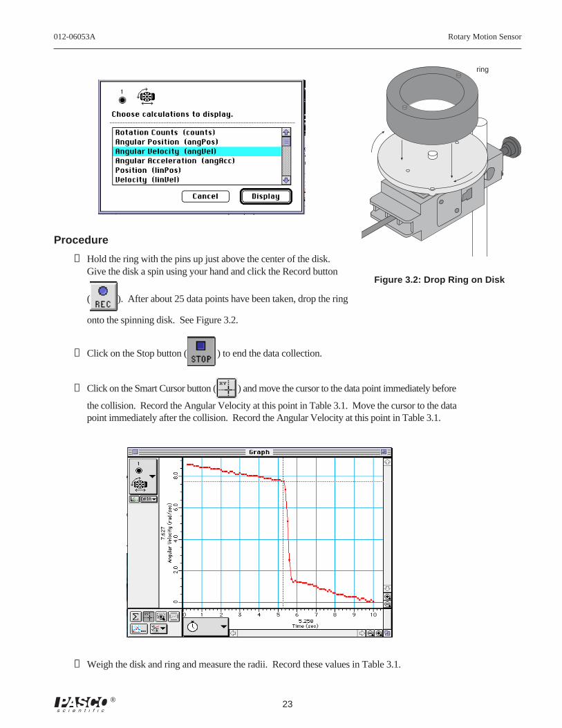
Procedure
➀ Hold the ring with the pins up just above the center of the disk.Give the disk a spin using your hand and click the Record button
( ). After about 25 data points have been taken, drop the ring
onto the spinning disk. See Figure 3.2.
➁ Click on the Stop button ( ) to end the data collection.
➂ Click on the Smart Cursor button ( ) and move the cursor to the data point immediately before
the collision. Record the Angular Velocity at this point in Table 3.1. Move the cursor to the datapoint immediately after the collision. Record the Angular Velocity at this point in Table 3.1.
➃ Weigh the disk and ring and measure the radii. Record these values in Table 3.1.
Figure 3.2: Drop Ring on Disk
ring
Rotary Motion Sensor 012-06053A
24 ®
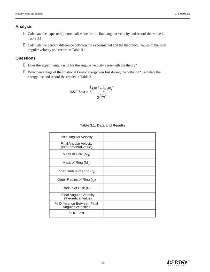
Analysis
➀ Calculate the expected (theoretical) value for the final angular velocity and record this value inTable 3.1.
➁ Calculate the percent difference between the experimental and the theoretical values of the finalangular velocity and record in Table 3.1.
Questions
➀ Does the experimental result for the angular velocity agree with the theory?
➁ What percentage of the rotational kinetic energy was lost during the collision? Calculate theenergy lost and record the results in Table 3.1.
%KE Lost =
12
Iiωi2 – 1
2I fω f
2
12
Iiωi2
Table 3.1: Data and Results
Initial Angular Velocity
Final Angular Velocity(experimental value)
Mass of Disk (M1)
Mass of Ring (M2)
Final Angular Velocity(theoretical value)
% Difference Between FinalAngular Velocities
Inner Radius of Ring (r1)
Outer Radius of Ring (r2)
Radius of Disk (R)
% KE lost
012-06053A Rotary Motion Sensor
25®
Suggested Experiments
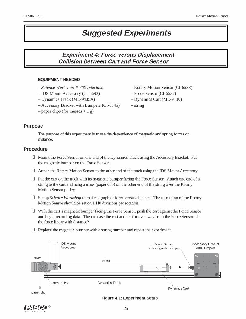
Experiment 4: Force versus Displacement –Collision between Cart and Force Sensor
EQUIPMENT NEEDED
– Science Workshop™ 700 Interface – Rotary Motion Sensor (CI-6538)– IDS Mount Accessory (CI-6692) – Force Sensor (CI-6537)– Dynamics Track (ME-9435A) – Dynamics Cart (ME-9430)– Accessory Bracket with Bumpers (CI-6545) – string– paper clips (for masses < 1 g)
Purpose
The purpose of this experiment is to see the dependence of magnetic and spring forces ondistance.
Procedure
➀ Mount the Force Sensor on one end of the Dynamics Track using the Accessory Bracket. Putthe magnetic bumper on the Force Sensor.
➁ Attach the Rotary Motion Sensor to the other end of the track using the IDS Mount Accessory.
➂ Put the cart on the track with its magnetic bumper facing the Force Sensor. Attach one end of astring to the cart and hang a mass (paper clip) on the other end of the string over the RotaryMotion Sensor pulley.
➃ Set up Science Workshop to make a graph of force versus distance. The resolution of the RotaryMotion Sensor should be set on 1440 divisions per rotation.
➄ With the cart’s magnetic bumper facing the Force Sensor, push the cart against the Force Sensorand begin recording data. Then release the cart and let it move away from the Force Sensor. Isthe force linear with distance?
➅ Replace the magnetic bumper with a spring bumper and repeat the experiment.
T
A R E
3-step Pulley
paper clip
stringRMS
Figure 4.1: Experiment Setup
Dynamics Track
Dynamics Cart
Accessory Bracketwith Bumpers
Force Sensorwith magnetic bumper
IDS MountAccessory
Rotary Motion Sensor 012-06053A
26 ®
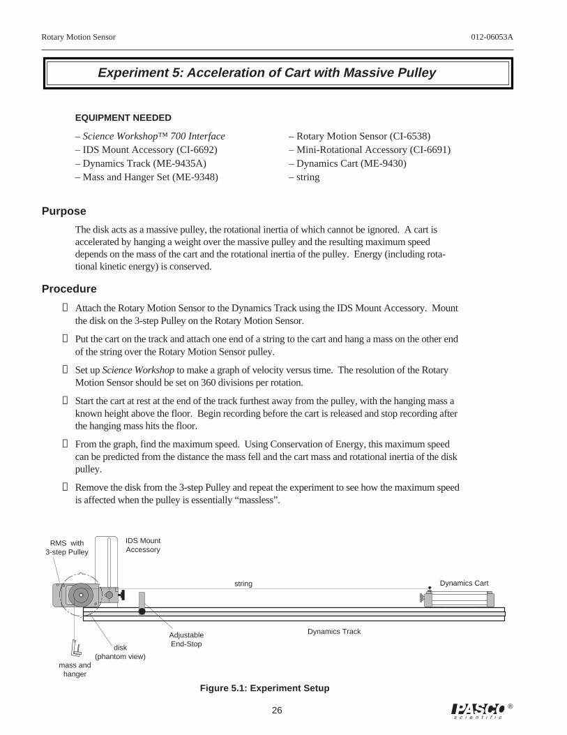
Experiment 5: Acceleration of Cart with Massive Pulley
Figure 5.1: Experiment Setup
EQUIPMENT NEEDED
– Science Workshop™ 700 Interface – Rotary Motion Sensor (CI-6538)– IDS Mount Accessory (CI-6692) – Mini-Rotational Accessory (CI-6691)– Dynamics Track (ME-9435A) – Dynamics Cart (ME-9430)– Mass and Hanger Set (ME-9348) – string
Purpose
The disk acts as a massive pulley, the rotational inertia of which cannot be ignored. A cart isaccelerated by hanging a weight over the massive pulley and the resulting maximum speeddepends on the mass of the cart and the rotational inertia of the pulley. Energy (including rota-tional kinetic energy) is conserved.
Procedure
➀ Attach the Rotary Motion Sensor to the Dynamics Track using the IDS Mount Accessory. Mountthe disk on the 3-step Pulley on the Rotary Motion Sensor.
➁ Put the cart on the track and attach one end of a string to the cart and hang a mass on the other endof the string over the Rotary Motion Sensor pulley.
➂ Set up Science Workshop to make a graph of velocity versus time. The resolution of the RotaryMotion Sensor should be set on 360 divisions per rotation.
➃ Start the cart at rest at the end of the track furthest away from the pulley, with the hanging mass aknown height above the floor. Begin recording before the cart is released and stop recording afterthe hanging mass hits the floor.
➄ From the graph, find the maximum speed. Using Conservation of Energy, this maximum speedcan be predicted from the distance the mass fell and the cart mass and rotational inertia of the diskpulley.
➅ Remove the disk from the 3-step Pulley and repeat the experiment to see how the maximum speedis affected when the pulley is essentially “massless”.
string Dynamics Cart
Dynamics Track
RMS with3-step Pulley
mass andhanger
AdjustableEnd-Stopdisk
(phantom view)
IDS MountAccessory
012-06053A Rotary Motion Sensor
27®
TARE
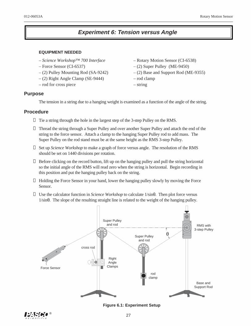
Experiment 6: Tension versus Angle
EQUIPMENT NEEDED
– Science Workshop™ 700 Interface – Rotary Motion Sensor (CI-6538)– Force Sensor (CI-6537) – (2) Super Pulley (ME-9450)– (2) Pulley Mounting Rod (SA-9242) – (2) Base and Support Rod (ME-9355)– (2) Right Angle Clamp (SE-9444) – rod clamp– rod for cross piece – string
Purpose
The tension in a string due to a hanging weight is examined as a function of the angle of the string.
Procedure
➀ Tie a string through the hole in the largest step of the 3-step Pulley on the RMS.
➁ Thread the string through a Super Pulley and over another Super Pulley and attach the end of thestring to the force sensor. Attach a clamp to the hanging Super Pulley rod to add mass. TheSuper Pulley on the rod stand must be at the same height as the RMS 3-step Pulley.
➂ Set up Science Workshop to make a graph of force versus angle. The resolution of the RMSshould be set on 1440 divisions per rotation.
➃ Before clicking on the record button, lift up on the hanging pulley and pull the string horizontalso the initial angle of the RMS will read zero when the string is horizontal. Begin recording inthis position and put the hanging pulley back on the string.
➄ Holding the Force Sensor in your hand, lower the hanging pulley slowly by moving the ForceSensor.
➅ Use the calculator function in Science Workshop to calculate 1/sinθ. Then plot force versus1/sinθ. The slope of the resulting straight line is related to the weight of the hanging pulley.
Super Pulleyand rod
cross rod
Figure 6.1: Experiment Setup
Force Sensor
RightAngle
Clamps
Super Pulleyand rod
rodclamp
RMS with3-step Pulley
Base andSupport Rod
θ
Rotary Motion Sensor 012-06053A
28 ®
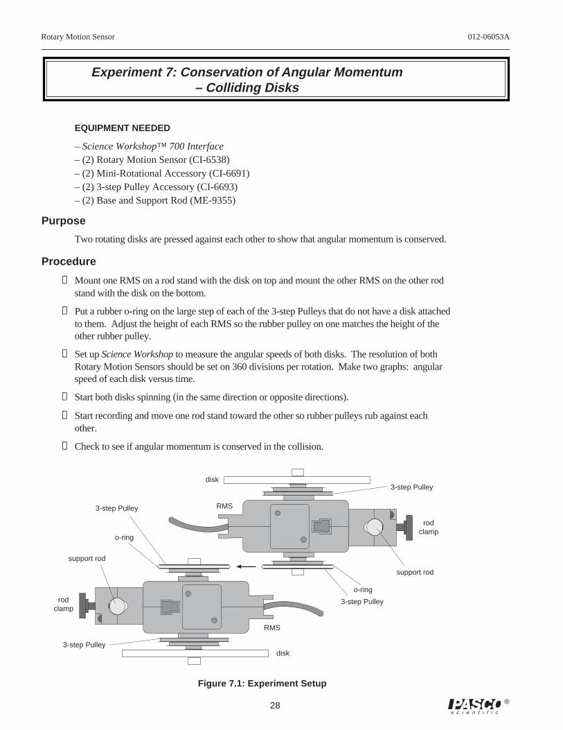
Experiment 7: Conservation of Angular Momentum– Colliding Disks
EQUIPMENT NEEDED
– Science Workshop™ 700 Interface– (2) Rotary Motion Sensor (CI-6538)– (2) Mini-Rotational Accessory (CI-6691)– (2) 3-step Pulley Accessory (CI-6693)– (2) Base and Support Rod (ME-9355)
Purpose
Two rotating disks are pressed against each other to show that angular momentum is conserved.
Procedure
➀ Mount one RMS on a rod stand with the disk on top and mount the other RMS on the other rodstand with the disk on the bottom.
➁ Put a rubber o-ring on the large step of each of the 3-step Pulleys that do not have a disk attachedto them. Adjust the height of each RMS so the rubber pulley on one matches the height of theother rubber pulley.
➂ Set up Science Workshop to measure the angular speeds of both disks. The resolution of bothRotary Motion Sensors should be set on 360 divisions per rotation. Make two graphs: angularspeed of each disk versus time.
➃ Start both disks spinning (in the same direction or opposite directions).
➄ Start recording and move one rod stand toward the other so rubber pulleys rub against eachother.
➅ Check to see if angular momentum is conserved in the collision.
Figure 7.1: Experiment Setup
3-step Pulley
o-ring
RMS
3-step Pulley
support rod
disk
RMS
disk
3-step Pulley
o-ring
support rod
rodclamp
rodclamp
3-step Pulley
012-06053A Rotary Motion Sensor
29®
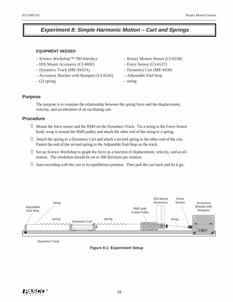
Experiment 8: Simple Harmonic Motion – Cart and Springs
EQUIPMENT NEEDED
– Science Workshop™ 700 Interface – Rotary Motion Sensor (CI-6538)– IDS Mount Accessory (CI-6692) – Force Sensor (CI-6537)– Dynamics Track (ME-9435A) – Dynamics Cart (ME-9430)– Accessory Bracket with Bumpers (CI-6545) – Adjustable End-Stop– (2) spring – string
Purpose
The purpose is to examine the relationship between the spring force and the displacement,velocity, and acceleration of an oscillating cart.
Procedure
➀ Mount the force sensor and the RMS on the Dynamics Track. Tie a string to the Force Sensorhook, wrap it around the RMS pulley and attach the other end of the string to a spring.
➁ Attach the spring to a Dynamics Cart and attach a second spring to the other end of the cart.Fasten the end of the second spring to the Adjustable End-Stop on the track.
➂ Set up Science Workshop to graph the force as a function of displacement, velocity, and accel-eration. The resolution should be set to 360 divisions per rotation.
➃ Start recording with the cart in its equilibrium position. Then pull the cart back and let it go.
T
A R E
IDS MountAccessory
Dynamics Cart
RMS with3-step Pulley
AdjustableEnd-Stop
Dynamics Track
AccessoryBracket with
Bumpers
ForceSensor
Figure 8.1: Experiment Setup
string
spring spring string
Rotary Motion Sensor 012-06053A
30 ®
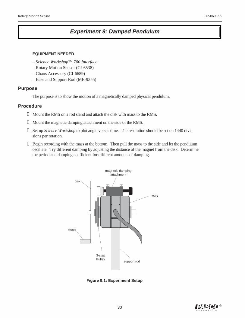
Experiment 9: Damped Pendulum
EQUIPMENT NEEDED
– Science Workshop™ 700 Interface– Rotary Motion Sensor (CI-6538)– Chaos Accessory (CI-6689)– Base and Support Rod (ME-9355)
Purpose
The purpose is to show the motion of a magnetically damped physical pendulum.
Procedure
➀ Mount the RMS on a rod stand and attach the disk with mass to the RMS.
➁ Mount the magnetic damping attachment on the side of the RMS.
➂ Set up Science Workshop to plot angle versus time. The resolution should be set on 1440 divi-sions per rotation.
➃ Begin recording with the mass at the bottom. Then pull the mass to the side and let the pendulumoscillate. Try different damping by adjusting the distance of the magnet from the disk. Determinethe period and damping coefficient for different amounts of damping.
support rod
disk
mass
RMS
magnetic dampingattachment
3-stepPulley
Figure 9.1: Experiment Setup
012-06053A Rotary Motion Sensor
31®
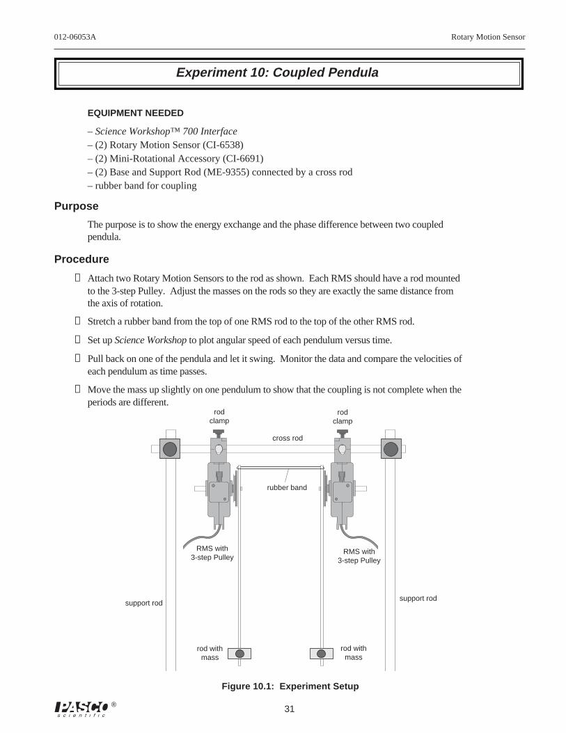
Experiment 10: Coupled Pendula
EQUIPMENT NEEDED
– Science Workshop™ 700 Interface– (2) Rotary Motion Sensor (CI-6538)– (2) Mini-Rotational Accessory (CI-6691)– (2) Base and Support Rod (ME-9355) connected by a cross rod– rubber band for coupling
Purpose
The purpose is to show the energy exchange and the phase difference between two coupledpendula.
Procedure
➀ Attach two Rotary Motion Sensors to the rod as shown. Each RMS should have a rod mountedto the 3-step Pulley. Adjust the masses on the rods so they are exactly the same distance fromthe axis of rotation.
➁ Stretch a rubber band from the top of one RMS rod to the top of the other RMS rod.
➂ Set up Science Workshop to plot angular speed of each pendulum versus time.
➃ Pull back on one of the pendula and let it swing. Monitor the data and compare the velocities ofeach pendulum as time passes.
➄ Move the mass up slightly on one pendulum to show that the coupling is not complete when theperiods are different.
rodclamp
rodclamp
rubber band
cross rod
RMS with3-step Pulley
RMS with3-step Pulley
support rodsupport rod
rod withmass
rod withmass
Figure 10.1: Experiment Setup
Rotary Motion Sensor 012-06053A
32 ®
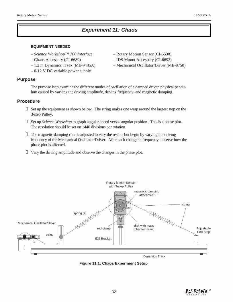
Experiment 11: Chaos
EQUIPMENT NEEDED
– Science Workshop™ 700 Interface – Rotary Motion Sensor (CI-6538)– Chaos Accessory (CI-6689) – IDS Mount Accessory (CI-6692)– 1.2 m Dynamics Track (ME-9435A) – Mechanical Oscillator/Driver (ME-8750)– 0-12 V DC variable power supply
Purpose
The purpose is to examine the different modes of oscillation of a damped driven physical pendu-lum caused by varying the driving amplitude, driving frequency, and magnetic damping.
Procedure
➀ Set up the equipment as shown below. The string makes one wrap around the largest step on the3-step Pulley.
➁ Set up Science Workshop to graph angular speed versus angular position. This is a phase plot.The resolution should be set on 1440 divisions per rotation.
➂ The magnetic damping can be adjusted to vary the results but begin by varying the drivingfrequency of the Mechanical Oscillator/Driver. After each change in frequency, observe how thephase plot is affected.
➃ Vary the driving amplitude and observe the changes in the phase plot.
Mechanical Oscillator/Driver
Dynamics Track
AdjustableEnd-Stop
Figure 11.1: Chaos Experiment Setup
string
string
Rotary Motion Sensorwith 3-step Pulley
spring (2)
IDS Bracket
rod clamp
magnetic dampingattachment
disk with mass(phantom view)
012-06053A Rotary Motion Sensor
33®
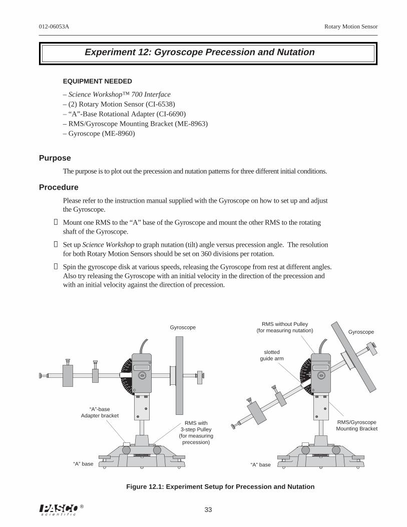
Experiment 12: Gyroscope Precession and Nutation
EQUIPMENT NEEDED
– Science Workshop™ 700 Interface– (2) Rotary Motion Sensor (CI-6538)– “A”-Base Rotational Adapter (CI-6690)– RMS/Gyroscope Mounting Bracket (ME-8963)– Gyroscope (ME-8960)
Purpose
The purpose is to plot out the precession and nutation patterns for three different initial conditions.
Procedure
Please refer to the instruction manual supplied with the Gyroscope on how to set up and adjustthe Gyroscope.
➀ Mount one RMS to the “A” base of the Gyroscope and mount the other RMS to the rotatingshaft of the Gyroscope.
➁ Set up Science Workshop to graph nutation (tilt) angle versus precession angle. The resolutionfor both Rotary Motion Sensors should be set on 360 divisions per rotation.
➂ Spin the gyroscope disk at various speeds, releasing the Gyroscope from rest at different angles.Also try releasing the Gyroscope with an initial velocity in the direction of the precession andwith an initial velocity against the direction of precession.
Figure 12.1: Experiment Setup for Precession and Nutation
90
100
110
120
130
140
80
70
60
50
4030
ME-8960DEMONSTRATION
GYROSCOPE
CAUTIONMAGNET
90
100
110
120
130
140
80
70
60
50
4030
ME-8960DEMONSTRATION
GYROSCOPE
CAUTIONMAGNET
RMS with3-step Pulley
(for measuringprecession)
“A”-baseAdapter bracket
“A” base “A” base
GyroscopeGyroscope
RMS/GyroscopeMounting Bracket
slottedguide arm
RMS without Pulley(for measuring nutation)
Rotary Motion Sensor 012-06053A
34 ®
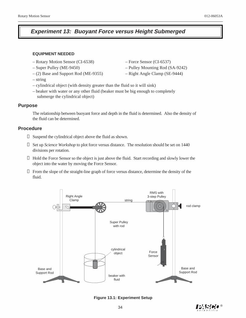
Experiment 13: Buoyant Force versus Height Submerged
EQUIPMENT NEEDED
– Rotary Motion Sensor (CI-6538) – Force Sensor (CI-6537)– Super Pulley (ME-9450) – Pulley Mounting Rod (SA-9242)– (2) Base and Support Rod (ME-9355) – Right Angle Clamp (SE-9444)– string– cylindrical object (with density greater than the fluid so it will sink)– beaker with water or any other fluid (beaker must be big enough to completely
submerge the cylindrical object)
Purpose
The relationship between buoyant force and depth in the fluid is determined. Also the density ofthe fluid can be determined.
Procedure
➀ Suspend the cylindrical object above the fluid as shown.
➁ Set up Science Workshop to plot force versus distance. The resolution should be set on 1440divisions per rotation.
➂ Hold the Force Sensor so the object is just above the fluid. Start recording and slowly lower theobject into the water by moving the Force Sensor.
➃ From the slope of the straight-line graph of force versus distance, determine the density of thefluid.
TAR
E
Super Pulleywith rod
string
ForceSensor
RMS with3-step Pulley
Base andSupport Rod
Right AngleClamp
Base andSupport Rod
rod clamp
cylindricalobject
beaker withfluid
Figure 13.1: Experiment Setup
012-06053A Rotary Motion Sensor
35®
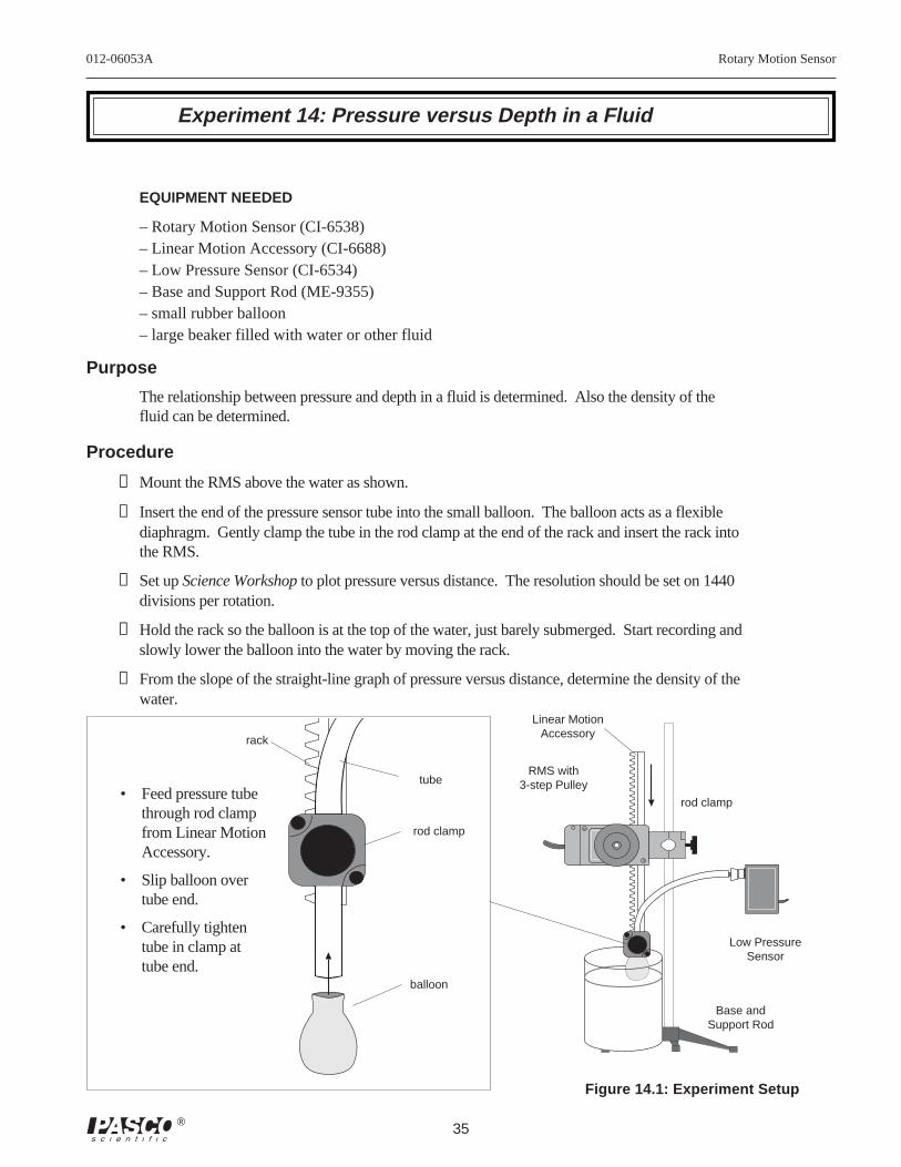
Experiment 14: Pressure versus Depth in a Fluid
EQUIPMENT NEEDED
– Rotary Motion Sensor (CI-6538)– Linear Motion Accessory (CI-6688)– Low Pressure Sensor (CI-6534)– Base and Support Rod (ME-9355)– small rubber balloon– large beaker filled with water or other fluid
Purpose
The relationship between pressure and depth in a fluid is determined. Also the density of thefluid can be determined.
Procedure
➀ Mount the RMS above the water as shown.
➁ Insert the end of the pressure sensor tube into the small balloon. The balloon acts as a flexiblediaphragm. Gently clamp the tube in the rod clamp at the end of the rack and insert the rack intothe RMS.
➂ Set up Science Workshop to plot pressure versus distance. The resolution should be set on 1440divisions per rotation.
➃ Hold the rack so the balloon is at the top of the water, just barely submerged. Start recording andslowly lower the balloon into the water by moving the rack.
➄ From the slope of the straight-line graph of pressure versus distance, determine the density of thewater.
RMS with3-step Pulley
rod clamp
tube
rod clamp
Low PressureSensor
rack
• Feed pressure tubethrough rod clampfrom Linear MotionAccessory.
• Slip balloon overtube end.
• Carefully tightentube in clamp attube end.
Linear MotionAccessory
balloon
Base andSupport Rod
Figure 14.1: Experiment Setup
Rotary Motion Sensor 012-06053A
36 ®
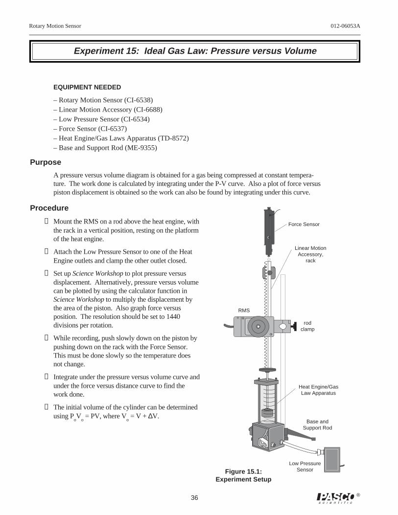
Experiment 15: Ideal Gas Law: Pressure versus Volume
EQUIPMENT NEEDED
– Rotary Motion Sensor (CI-6538)– Linear Motion Accessory (CI-6688)– Low Pressure Sensor (CI-6534)– Force Sensor (CI-6537)– Heat Engine/Gas Laws Apparatus (TD-8572)– Base and Support Rod (ME-9355)
Purpose
A pressure versus volume diagram is obtained for a gas being compressed at constant tempera-ture. The work done is calculated by integrating under the P-V curve. Also a plot of force versuspiston displacement is obtained so the work can also be found by integrating under this curve.
Procedure
➀ Mount the RMS on a rod above the heat engine, withthe rack in a vertical position, resting on the platformof the heat engine.
➁ Attach the Low Pressure Sensor to one of the HeatEngine outlets and clamp the other outlet closed.
➂ Set up Science Workshop to plot pressure versusdisplacement. Alternatively, pressure versus volumecan be plotted by using the calculator function inScience Workshop to multiply the displacement bythe area of the piston. Also graph force versusposition. The resolution should be set to 1440divisions per rotation.
➃ While recording, push slowly down on the piston bypushing down on the rack with the Force Sensor.This must be done slowly so the temperature doesnot change.
➄ Integrate under the pressure versus volume curve andunder the force versus distance curve to find thework done.
➅ The initial volume of the cylinder can be determinedusing P
oV
o = PV, where V
o = V + ∆V.
TAR
E
Force Sensor
Low PressureSensor
rodclamp
RMS
Linear MotionAccessory,
rack
Heat Engine/GasLaw Apparatus
Base andSupport Rod
Figure 15.1:Experiment Setup
012-06053A Rotary Motion Sensor
37®
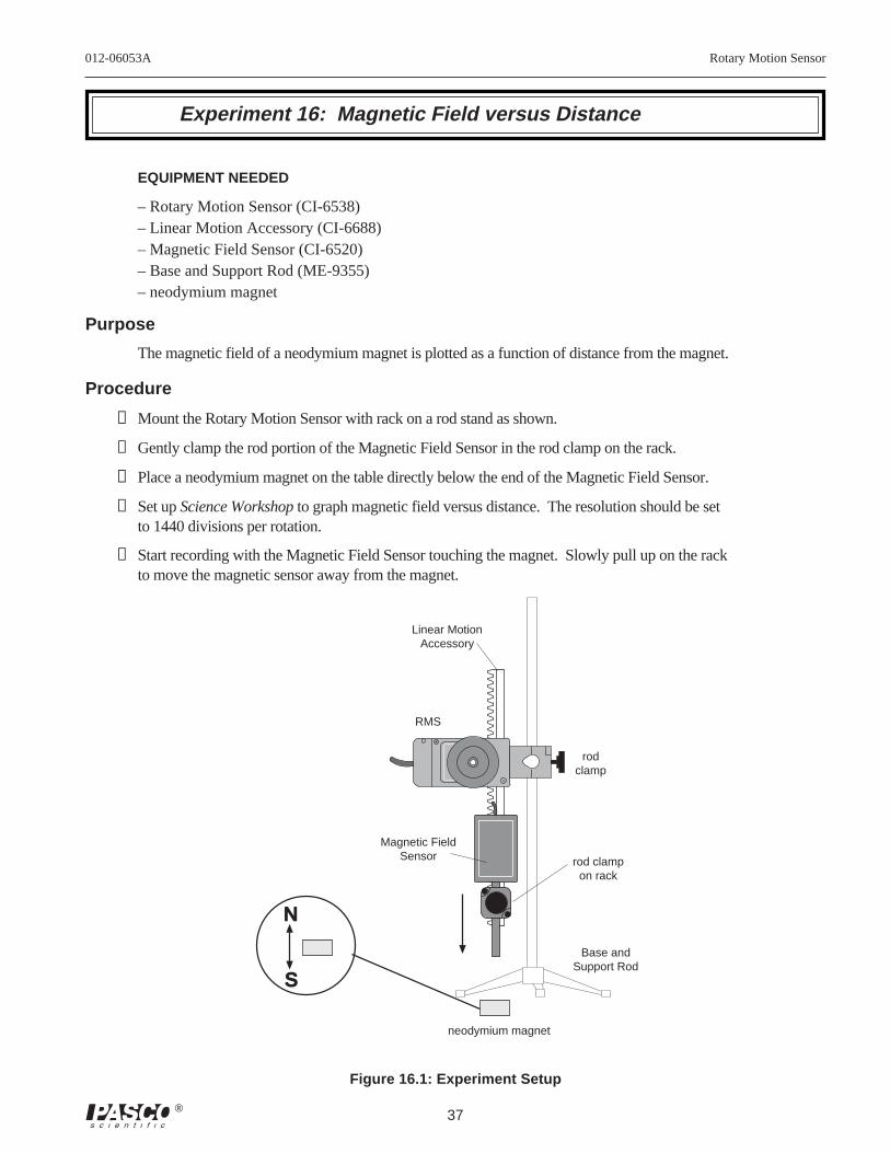
Experiment 16: Magnetic Field versus Distance
EQUIPMENT NEEDED
– Rotary Motion Sensor (CI-6538)– Linear Motion Accessory (CI-6688)– Magnetic Field Sensor (CI-6520)– Base and Support Rod (ME-9355)– neodymium magnet
Purpose
The magnetic field of a neodymium magnet is plotted as a function of distance from the magnet.
Procedure
➀ Mount the Rotary Motion Sensor with rack on a rod stand as shown.
➁ Gently clamp the rod portion of the Magnetic Field Sensor in the rod clamp on the rack.
➂ Place a neodymium magnet on the table directly below the end of the Magnetic Field Sensor.
➃ Set up Science Workshop to graph magnetic field versus distance. The resolution should be setto 1440 divisions per rotation.
➅ Start recording with the Magnetic Field Sensor touching the magnet. Slowly pull up on the rackto move the magnetic sensor away from the magnet.
N
S
Base andSupport Rod
RMS
rodclamp
Magnetic FieldSensor
neodymium magnet
Linear MotionAccessory
rod clampon rack
Figure 16.1: Experiment Setup
Rotary Motion Sensor 012-06053A
38 ®
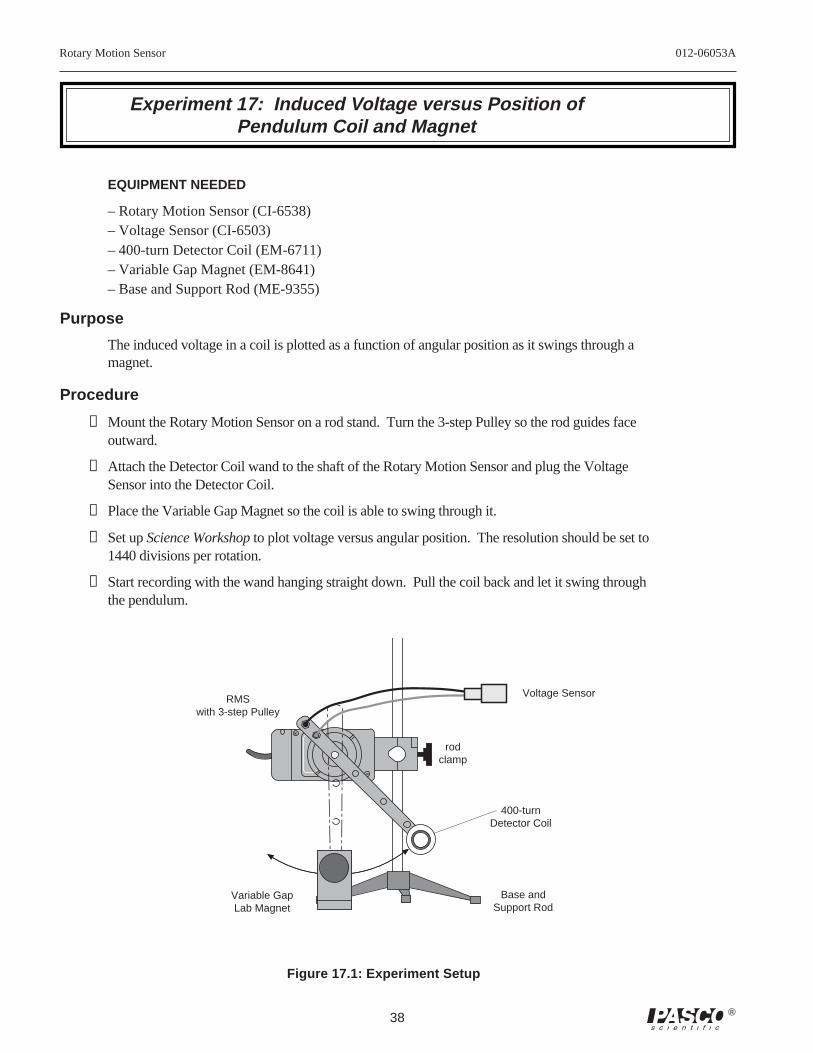
Experiment 17: Induced Voltage versus Position ofPendulum Coil and Magnet
EQUIPMENT NEEDED
– Rotary Motion Sensor (CI-6538)– Voltage Sensor (CI-6503)– 400-turn Detector Coil (EM-6711)– Variable Gap Magnet (EM-8641)– Base and Support Rod (ME-9355)
Purpose
The induced voltage in a coil is plotted as a function of angular position as it swings through amagnet.
Procedure
➀ Mount the Rotary Motion Sensor on a rod stand. Turn the 3-step Pulley so the rod guides faceoutward.
➁ Attach the Detector Coil wand to the shaft of the Rotary Motion Sensor and plug the VoltageSensor into the Detector Coil.
➂ Place the Variable Gap Magnet so the coil is able to swing through it.
➃ Set up Science Workshop to plot voltage versus angular position. The resolution should be set to1440 divisions per rotation.
➄ Start recording with the wand hanging straight down. Pull the coil back and let it swing throughthe pendulum.
Base andSupport Rod
Figure 17.1: Experiment Setup
rodclamp
Voltage Sensor
400-turnDetector Coil
Variable GapLab Magnet
RMSwith 3-step Pulley
012-06053A Rotary Motion Sensor
39®
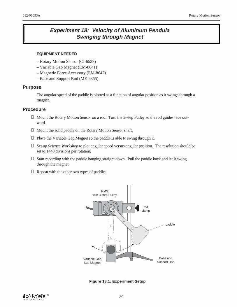
Experiment 18: Velocity of Aluminum PendulaSwinging through Magnet
EQUIPMENT NEEDED
– Rotary Motion Sensor (CI-6538)– Variable Gap Magnet (EM-8641)– Magnetic Force Accessory (EM-8642)– Base and Support Rod (ME-9355)
Purpose
The angular speed of the paddle is plotted as a function of angular position as it swings through amagnet.
Procedure
➀ Mount the Rotary Motion Sensor on a rod. Turn the 3-step Pulley so the rod guides face out-ward.
➁ Mount the solid paddle on the Rotary Motion Sensor shaft.
➂ Place the Variable Gap Magnet so the paddle is able to swing through it.
➃ Set up Science Workshop to plot angular speed versus angular position. The resolution should beset to 1440 divisions per rotation.
➄ Start recording with the paddle hanging straight down. Pull the paddle back and let it swingthrough the magnet.
➅ Repeat with the other two types of paddles.
Figure 18.1: Experiment Setup
Base andSupport Rod
rodclamp
paddle
Variable GapLab Magnet
RMSwith 3-step Pulley
Rotary Motion Sensor 012-06053A
40 ®
Experiment 19: Light Intensity versus Distance
EQUIPMENT NEEDED
– Rotary Motion Sensor (CI-6538) – IDS Mount Accessory (CI-6692)– Dynamics Track (ME-9435A) – Dynamics Cart (ME-9430)– Light Source (OS-8517) – Light Sensor (CI-6504)– Mass and Hanger Set (ME-9348) – string –block
Purpose
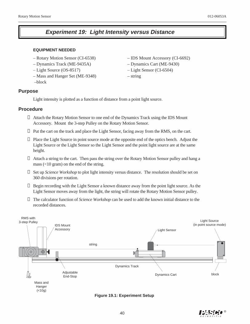
Light intensity is plotted as a function of distance from a point light source.
Procedure
➀ Attach the Rotary Motion Sensor to one end of the Dynamics Track using the IDS MountAccessory. Mount the 3-step Pulley on the Rotary Motion Sensor.
➁ Put the cart on the track and place the Light Sensor, facing away from the RMS, on the cart.
➂ Place the Light Source in point source mode at the opposite end of the optics bench. Adjust theLight Source or the Light Sensor so the Light Sensor and the point light source are at the sameheight.
➃ Attach a string to the cart. Then pass the string over the Rotary Motion Sensor pulley and hang amass (<10 gram) on the end of the string.
➄ Set up Science Workshop to plot light intensity versus distance. The resolution should be set on360 divisions per rotation.
➅ Begin recording with the Light Sensor a known distance away from the point light source. As theLight Sensor moves away from the light, the string will rotate the Rotary Motion Sensor pulley.
➆ The calculator function of Science Workshop can be used to add the known initial distance to therecorded distances.
RMS with3-step Pulley
IDS MountAccessory
Dynamics Track
Dynamics Cart
Light Sensor
Light Source(in point source mode)
block
Figure 19.1: Experiment Setup
string
Mass andHanger(<10g)
AdjustableEnd-Stop

012-06053A Rotary Motion Sensor
41®
Technical Support
Contacting Technical Support
Before you call the PASCO Technical Support staff itwould be helpful to prepare the following information:
• If your problem is computer/software related, note:
Title and Revision Date of software.
Type of Computer (Make, Model, Speed).
Type of external Cables/Peripherals.
• If your problem is with the PASCO apparatus, note:
Title and Model number (usually listed on the label).
Approximate age of apparatus.
A detailed description of the problem/sequence ofevents. (In case you can't call PASCO right away, youwon't lose valuable data.)
If possible, have the apparatus within reach when call-ing. This makes descriptions of individual parts mucheasier.
• If your problem relates to the instruction manual, note:
Part number and Revision (listed by month and year onthe front cover).
Have the manual at hand to discuss your questions.
Feed-Back
If you have any comments about this product or thismanual please let us know. If you have any suggestionson alternate experiments or find a problem in the manualplease tell us. PASCO appreciates any customer feed-back. Your input helps us evaluate and improve ourproduct.
To Reach PASCO
For Technical Support call us at 1-800-772-8700 (toll-free within the U.S.) or (916) 786-3800.
email: [email protected]
Tech support fax: (916) 786-3292
Web: http://www.pasco.com