Embed Size (px)
Citation preview
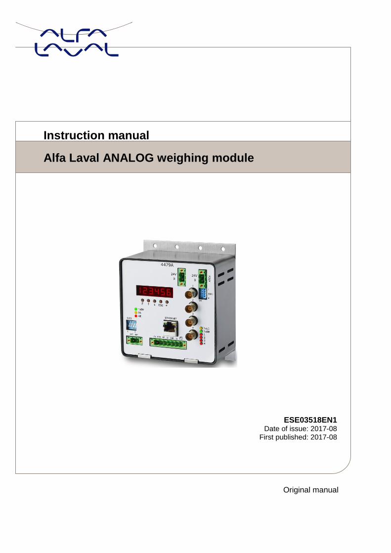
Instruction manual
Alfa Laval ANALOG weighing module
Original manual
ESE03518EN1 Date of issue: 2017-08
First published: 2017-08
Page: 2
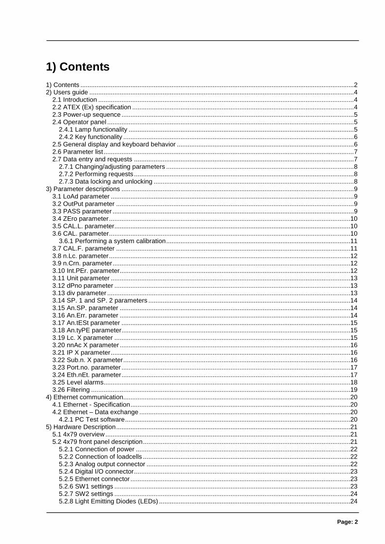
1) Contents
1) Contents ......................................................................................................................................................... 2 2) Users guide .................................................................................................................................................... 4
2.1 Introduction ............................................................................................................................................... 4 2.2 ATEX (Ex) specification ............................................................................................................................ 4 2.3 Power-up sequence .................................................................................................................................. 5 2.4 Operator panel .......................................................................................................................................... 5
2.4.1 Lamp functionality .............................................................................................................................. 5 2.4.2 Key functionality ................................................................................................................................. 6
2.5 General display and keyboard behavior ................................................................................................... 6 2.6 Parameter list ............................................................................................................................................ 7 2.7 Data entry and requests ........................................................................................................................... 7
2.7.1 Changing/adjusting parameters ......................................................................................................... 8 2.7.2 Performing requests ........................................................................................................................... 8 2.7.3 Data locking and unlocking ................................................................................................................ 8
3) Parameter descriptions .................................................................................................................................. 9 3.1 LoAd parameter ........................................................................................................................................ 9 3.2 OutPut parameter ..................................................................................................................................... 9 3.3 PASS parameter ....................................................................................................................................... 9 3.4 ZEro parameter ....................................................................................................................................... 10 3.5 CAL.L. parameter .................................................................................................................................... 10 3.6 CAL. parameter ....................................................................................................................................... 10
3.6.1 Performing a system calibration ....................................................................................................... 11 3.7 CAL.F. parameter ................................................................................................................................... 11 3.8 n.Lc. parameter ....................................................................................................................................... 12 3.9 n.Crn. parameter ..................................................................................................................................... 12 3.10 Int.PEr. parameter ................................................................................................................................. 12 3.11 Unit parameter ...................................................................................................................................... 13 3.12 dPno parameter .................................................................................................................................... 13 3.13 div parameter ........................................................................................................................................ 13 3.14 SP. 1 and SP. 2 parameters ................................................................................................................. 14 3.15 An.SP. parameter ................................................................................................................................. 14 3.16 An.Err. parameter ................................................................................................................................. 14 3.17 An.tESt parameter ................................................................................................................................ 15 3.18 An.tyPE parameter ................................................................................................................................ 15 3.19 Lc. X parameter .................................................................................................................................... 15 3.20 nnAc X parameter ................................................................................................................................. 16 3.21 IP X parameter ...................................................................................................................................... 16 3.22 Sub.n. X parameter ............................................................................................................................... 16 3.23 Port.no. parameter ................................................................................................................................ 17 3.24 Eth.nEt. parameter ................................................................................................................................ 17 3.25 Level alarms .......................................................................................................................................... 18 3.26 Filtering ................................................................................................................................................. 19
4) Ethernet communication............................................................................................................................... 20 4.1 Ethernet - Specification ........................................................................................................................... 20 4.2 Ethernet – Data exchange ...................................................................................................................... 20
4.2.1 PC Test software .............................................................................................................................. 20 5) Hardware Description ................................................................................................................................... 21
5.1 4x79 overview ......................................................................................................................................... 21 5.2 4x79 front panel description .................................................................................................................... 21
5.2.1 Connection of power ........................................................................................................................ 22 5.2.2 Connection of loadcells .................................................................................................................... 22 5.2.3 Analog output connector .................................................................................................................. 22 5.2.4 Digital I/O connector ......................................................................................................................... 23 5.2.5 Ethernet connector ........................................................................................................................... 23 5.2.6 SW1 settings .................................................................................................................................... 23 5.2.7 SW2 settings .................................................................................................................................... 24 5.2.8 Light Emitting Diodes (LEDs) ........................................................................................................... 24
Page: 3
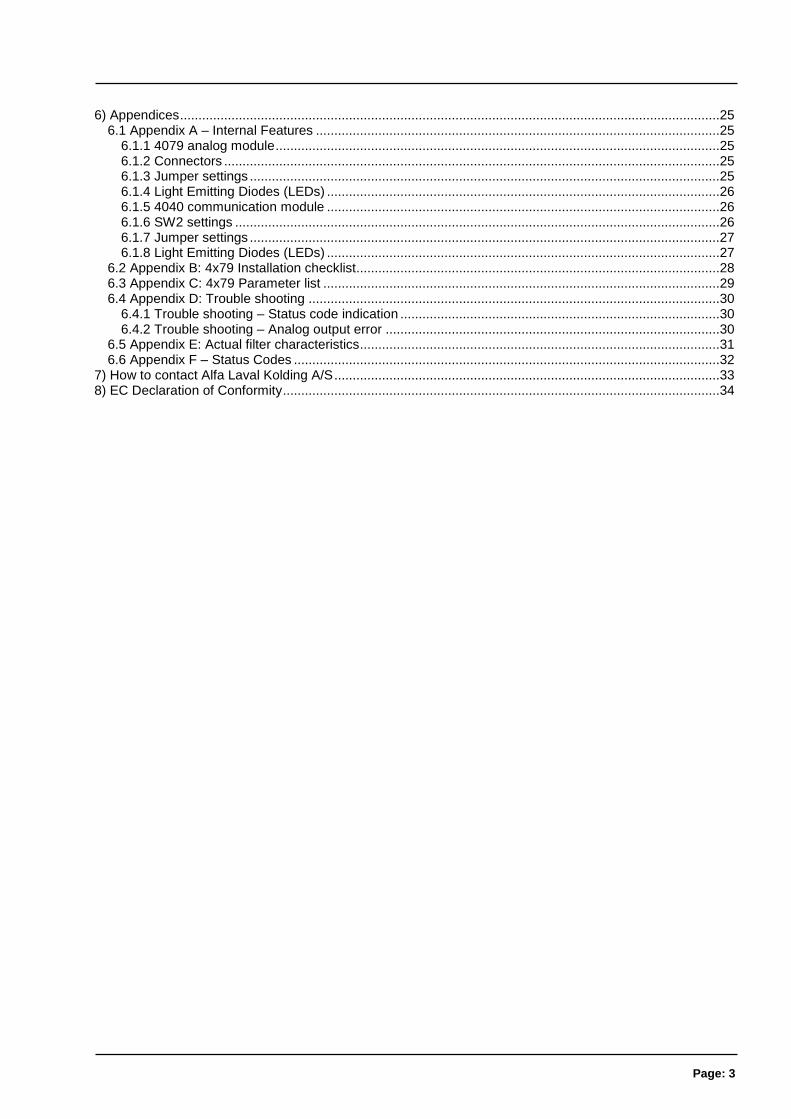
6) Appendices ................................................................................................................................................... 25 6.1 Appendix A – Internal Features .............................................................................................................. 25
6.1.1 4079 analog module ......................................................................................................................... 25 6.1.2 Connectors ....................................................................................................................................... 25 6.1.3 Jumper settings ................................................................................................................................ 25 6.1.4 Light Emitting Diodes (LEDs) ........................................................................................................... 26 6.1.5 4040 communication module ........................................................................................................... 26 6.1.6 SW2 settings .................................................................................................................................... 26 6.1.7 Jumper settings ................................................................................................................................ 27 6.1.8 Light Emitting Diodes (LEDs) ........................................................................................................... 27
6.2 Appendix B: 4x79 Installation checklist................................................................................................... 28 6.3 Appendix C: 4x79 Parameter list ............................................................................................................ 29 6.4 Appendix D: Trouble shooting ................................................................................................................ 30
6.4.1 Trouble shooting – Status code indication ....................................................................................... 30 6.4.2 Trouble shooting – Analog output error ........................................................................................... 30
6.5 Appendix E: Actual filter characteristics.................................................................................................. 31 6.6 Appendix F – Status Codes .................................................................................................................... 32
7) How to contact Alfa Laval Kolding A/S ......................................................................................................... 33 8) EC Declaration of Conformity ....................................................................................................................... 34
Page: 4
2) Users guide
2.1 Introduction
This document describes the 4x79 analog module from Alfa Laval Kolding A/S, when equipped with the software version stated on the front page. The 4x79 system unit consists internally of a 4079 analog module (with the software listed on the front page) and a 4040 communication mod-ule.
The 4x79 system unit is connected to X loadcells (1-4).
With the software version specified on the front page, the 4x79 analog module is capable of trans-mitting the weight for a system with up to 4 loadcells as an analog 4-20 mA signal (or 0-10V de-pending on factory settings) as well as on the Ethernet connection.
The 4x79 analog module is operated using a 6 digit display and 5 keys for viewing/configuring a series of system parameters.
By use of DIP switches it is possible to include one of 15 different FIR filters, that will be used to filter the weight signal.
2.2 ATEX (Ex) specification
IMPORTANT: Instrumentation (the 4x79A) must be placed outside the hazardous zone if the load cells are used in hazardous ATEX (Ex) area. Furthermore, only ATEX certified load cells and instrumentation can be used in ATEX applications.
Note: The illustrations and specifications contained in this manual were effective at the date of printing.
However, as continuous improvements are our policy, we reserve the right to alter or modify any unit speci-
fication on any product without prior notice or any obligation.
Page: 5
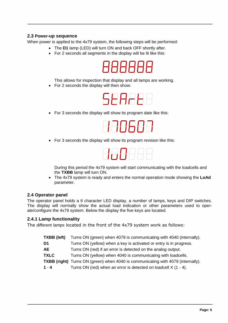
2.3 Power-up sequence
When power is applied to the 4x79 system, the following steps will be performed:
The D1 lamp (LED) will turn ON and back OFF shortly after.
For 2 seconds all segments in the display will be lit like this:
This allows for inspection that display and all lamps are working.
For 2 seconds the display will then show:
For 3 seconds the display will show its program date like this:
For 3 seconds the display will show its program revision like this:
During this period the 4x79 system will start communicating with the loadcells and the TXBB lamp will turn ON.
The 4x79 system is ready and enters the normal operation mode showing the LoAd parameter.
2.4 Operator panel
The operator panel holds a 6 character LED display, a number of lamps, keys and DIP switches. The display will normally show the actual load indication or other parameters used to oper-ate/configure the 4x79 system. Below the display the five keys are located.
2.4.1 Lamp functionality
The different lamps located in the front of the 4x79 system work as follows:
TXBB (left) Turns ON (green) when 4079 is communicating with 4040 (internally).
D1 Turns ON (yellow) when a key is activated or entry is in progress.
AE Turns ON (red) if an error is detected on the analog output.
TXLC Turns ON (yellow) when 4040 is communicating with loadcells.
TXBB (right) Turns ON (green) when 4040 is communicating with 4079 (internally).
1 - 4 Turns ON (red) when an error is detected on loadcell X (1 - 4).
Page: 6
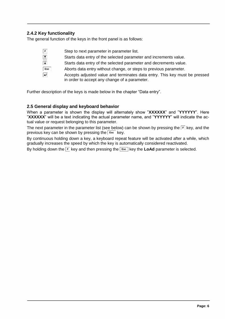
2.4.2 Key functionality
The general function of the keys in the front panel is as follows:
F Step to next parameter in parameter list.
Starts data entry of the selected parameter and increments value.
Starts data entry of the selected parameter and decrements value.
Esc Aborts data entry without change, or steps to previous parameter.
Accepts adjusted value and terminates data entry. This key must be pressed in order to accept any change of a parameter.
Further description of the keys is made below in the chapter “Data entry”.
2.5 General display and keyboard behavior
When a parameter is shown the display will alternately show ”XXXXXX” and ”YYYYYY”. Here ”XXXXXX” will be a text indicating the actual parameter name, and ”YYYYYY” will indicate the ac-tual value or request belonging to this parameter.
The next parameter in the parameter list (see below) can be shown by pressing the F key, and the previous key can be shown by pressing the Esc key.
By continuous holding down a key, a keyboard repeat feature will be activated after a while, which gradually increases the speed by which the key is automatically considered reactivated.
By holding down the F key and then pressing the Esc key the LoAd parameter is selected.
Page: 7
2.6 Parameter list
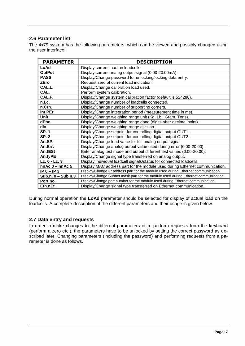
The 4x79 system has the following parameters, which can be viewed and possibly changed using the user interface:
PARAMETER DESCRIPTION LoAd Display current load on loadcells.
OutPut Display current analog output signal (0.00-20.00mA).
PASS Display/Change password for unlocking/locking data entry.
ZEro Request zero of current load indication.
CAL.L. Display/Change calibration load used.
CAL. Perform system calibration.
CAL.F. Display/Change system calibration factor (default is 524288).
n.Lc. Display/Change number of loadcells connected.
n.Crn. Display/Change number of supporting corners.
Int.PEr. Display/Change integration period (measurement time in ms).
Unit Display/Change weighing range unit (Kg, Lb., Gram, Tons).
dPno Display/Change weighing range dpno (digits after decimal point).
div Display/Change weighing range division.
SP. 1 Display/Change setpoint for controlling digital output OUT1.
SP. 2 Display/Change setpoint for controlling digital output OUT2.
An.SP. Display/Change load value for full analog output signal.
An.Err. Display/Change analog output value used during error (0.00-20.00).
An.tESt Enter analog test mode and output different test values (0.00-20.00).
An.tyPE Display/Change signal type transferred on analog output.
Lc. 0 - Lc. 3 Display individual loadcell signals/status for connected loadcells.
nnAc 0 – nnAc 5 Display MAC address part for the module used during Ethernet communication.
IP 0 – IP 3 Display/Change IP address part for the module used during Ethernet communication.
Sub.n. 0 – Sub.n.3 Display/Change Subnet mask part for the module used during Ethernet communication.
Port.no. Display/Change port number for the module used during Ethernet communication.
Eth.nEt. Display/Change signal type transferred on Ethernet communication.
During normal operation the LoAd parameter should be selected for display of actual load on the loadcells. A complete description of the different parameters and their usage is given below.
2.7 Data entry and requests
In order to make changes to the different parameters or to perform requests from the keyboard (perform a zero etc.), the parameters have to be unlocked by setting the correct password as de-scribed later. Changing parameters (including the password) and performing requests from a pa-rameter is done as follows.
Page: 8
2.7.1 Changing/adjusting parameters
Once a parameter is selected, then its value can be changed/adjusted by using the keys as fol-lows:
or Use the up and down keys until the desired value is reached.
Once the desired value is reached, the key MUST be pressed in order to accept the new parameter value.
Esc or F Aborts data entry without any changes to the parameter value.
Please note that some parameters can only be set to certain predetermined values. When parame-ter entry is in progress the yellow D1 lamp will be ON to indicate this. The D1 lamp will turn OFF once the data entry is completed by pressing the key or aborted by pressing the Esc key or the
F key.
Example - Changing calibration load from 0.000 to 1.250:
After having ensured the correct password is set use the F key (possibly the Esc key instead) to step forward (or backwards) to the CAL.L. parameter.
Then use the key and the key until the display shows 1.250.
The yellow D1 lamp will be ON during the above process.
Press the key to accept the new value and complete the data entry.
The yellow D1 lamp will turn OFF once the data entry is completed.
2.7.2 Performing requests
Some parameters are used to perform requests (such as zeroing) instead of changing/adjusting a parameter. Once such a parameter is selected, then the corresponding request can be performed by using the keys as follows:
Press the key to perform the selected request.
Example – Performing a zero when display shows 0.120:
After having ensured the correct password is set use the F key (possibly the Esc key instead) to step forward (or backwards) to the ZEro parameter where the load indication shows 0.120.
Then press the key to perform the zero.
Inspect that the request has been performed and that the load indication shows 0.000.
2.7.3 Data locking and unlocking
When the power is turned on all parameters are locked. The parameters can be unlocked by set-ting the correct password in the PASS parameter. As long as the password differs from the correct password, ALL parameter change and user requests from the keyboard are locked. The password for unlocking and allowing parameter change is:
1357
Note: If the display is left showing the LoAd parameter without any keyboard activity for 5 minutes or more, the password will automatically reset to 0.
Page: 9
3) Parameter descriptions
The following is a description of each available parameter for this application.
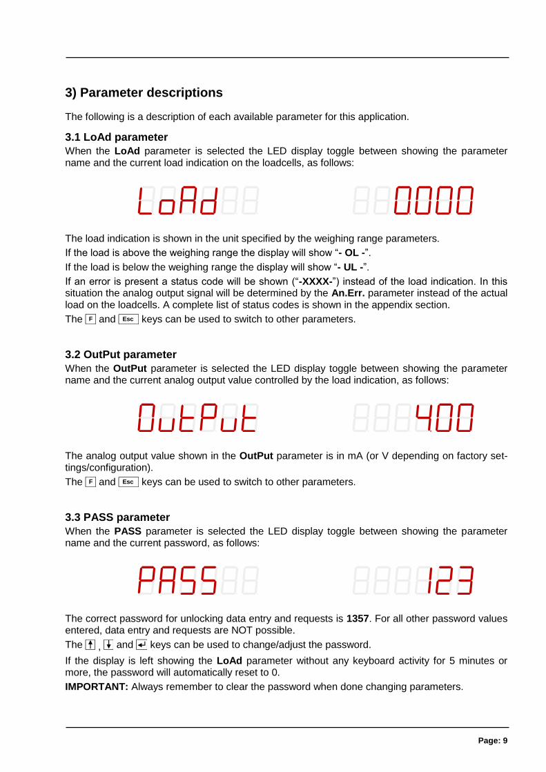
3.1 LoAd parameter
When the LoAd parameter is selected the LED display toggle between showing the parameter name and the current load indication on the loadcells, as follows:
The load indication is shown in the unit specified by the weighing range parameters.
If the load is above the weighing range the display will show “- OL -”.
If the load is below the weighing range the display will show “- UL -”.
If an error is present a status code will be shown (“-XXXX-”) instead of the load indication. In this situation the analog output signal will be determined by the An.Err. parameter instead of the actual load on the loadcells. A complete list of status codes is shown in the appendix section.
The F and Esc keys can be used to switch to other parameters.
3.2 OutPut parameter
When the OutPut parameter is selected the LED display toggle between showing the parameter name and the current analog output value controlled by the load indication, as follows:
The analog output value shown in the OutPut parameter is in mA (or V depending on factory set-tings/configuration).
The F and Esc keys can be used to switch to other parameters.
3.3 PASS parameter
When the PASS parameter is selected the LED display toggle between showing the parameter name and the current password, as follows:
The correct password for unlocking data entry and requests is 1357. For all other password values entered, data entry and requests are NOT possible.
The , and keys can be used to change/adjust the password.
If the display is left showing the LoAd parameter without any keyboard activity for 5 minutes or more, the password will automatically reset to 0.
IMPORTANT: Always remember to clear the password when done changing parameters.
Page: 10
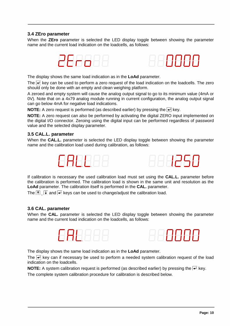
3.4 ZEro parameter
When the ZEro parameter is selected the LED display toggle between showing the parameter name and the current load indication on the loadcells, as follows:
The display shows the same load indication as in the LoAd parameter.
The key can be used to perform a zero request of the load indication on the loadcells. The zero should only be done with an empty and clean weighing platform.
A zeroed and empty system will cause the analog output signal to go to its minimum value (4mA or 0V). Note that on a 4x79 analog module running in current configuration, the analog output signal can go below 4mA for negative load indications.
NOTE: A zero request is performed (as described earlier) by pressing the key.
NOTE: A zero request can also be performed by activating the digital ZERO input implemented on the digital I/O connector. Zeroing using the digital input can be performed regardless of password value and the selected display parameter.
3.5 CAL.L. parameter
When the CAL.L. parameter is selected the LED display toggle between showing the parameter name and the calibration load used during calibration, as follows:
If calibration is necessary the used calibration load must set using the CAL.L. parameter before the calibration is performed. The calibration load is shown in the same unit and resolution as the LoAd parameter. The calibration itself is performed in the CAL. parameter.
The , and keys can be used to change/adjust the calibration load.
3.6 CAL. parameter
When the CAL. parameter is selected the LED display toggle between showing the parameter name and the current load indication on the loadcells, as follows:
The display shows the same load indication as in the LoAd parameter.
The key can if necessary be used to perform a needed system calibration request of the load indication on the loadcells.
NOTE: A system calibration request is performed (as described earlier) by pressing the key.
The complete system calibration procedure for calibration is described below.
Page: 11
3.6.1 Performing a system calibration
If necessary, it is possible to perform a system calibration from the CAL. parameter by performing the following system calibration procedure:
Allow calibration by entering correct password in the PASS parameter.
Ensure the weighing scale is empty and clean.
Use the ZEro parameter to zero the load indication if necessary.
Use the CAL.L. parameter to enter the used calibration load. Please notice that the accuracy of the calibration is deeply dependent on the accuracy and size of the cali-bration load. Please select a load with a mass not less than the maximum load nor-mally applied to the system.
Place the calibration load on the weighing arrangement.
Select the CAL. parameter, and to request the system calibration the key is now pressed.
The load indication shown in the CAL. parameter and several other parameters will now match the used calibration load and the system calibration factor has been up-dated correspondingly.
Use the CAL.F. parameter and note the achieved calibration factor, so that the cali-bration can be re-established later.
The system is now calibrated and the calibration should be protected by clearing the password (set to 0).
Select LoAd parameter verify that a given load results in a matching weight indica-tion.
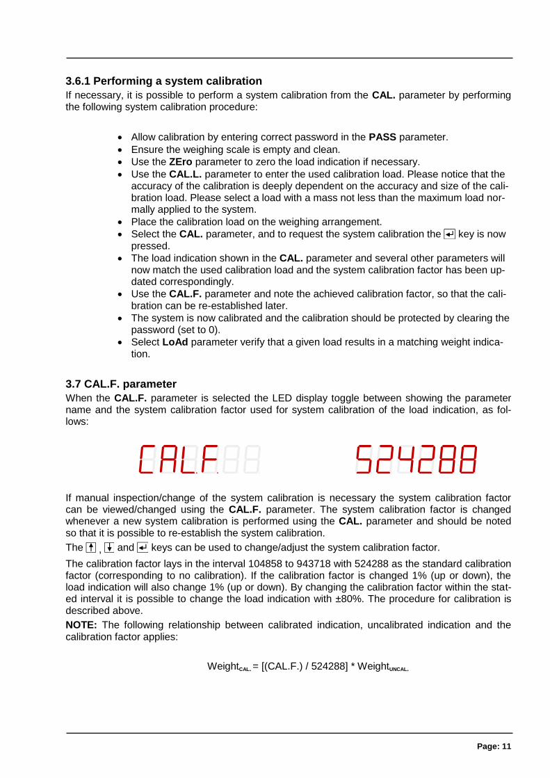
3.7 CAL.F. parameter
When the CAL.F. parameter is selected the LED display toggle between showing the parameter name and the system calibration factor used for system calibration of the load indication, as fol-lows:
If manual inspection/change of the system calibration is necessary the system calibration factor can be viewed/changed using the CAL.F. parameter. The system calibration factor is changed whenever a new system calibration is performed using the CAL. parameter and should be noted so that it is possible to re-establish the system calibration.
The , and keys can be used to change/adjust the system calibration factor.
The calibration factor lays in the interval 104858 to 943718 with 524288 as the standard calibration factor (corresponding to no calibration). If the calibration factor is changed 1% (up or down), the load indication will also change 1% (up or down). By changing the calibration factor within the stat-ed interval it is possible to change the load indication with ±80%. The procedure for calibration is described above.
NOTE: The following relationship between calibrated indication, uncalibrated indication and the calibration factor applies:
WeightCAL. = [(CAL.F.) / 524288] * WeightUNCAL.
Page: 12
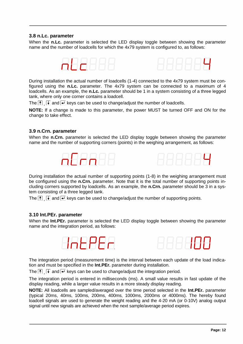
3.8 n.Lc. parameter
When the n.Lc. parameter is selected the LED display toggle between showing the parameter name and the number of loadcells for which the 4x79 system is configured to, as follows:
During installation the actual number of loadcells (1-4) connected to the 4x79 system must be con-figured using the n.Lc. parameter. The 4x79 system can be connected to a maximum of 4 loadcells. As an example, the n.Lc. parameter should be 1 in a system consisting of a three legged tank, where only one corner contains a loadcell.
The , and keys can be used to change/adjust the number of loadcells.
NOTE: If a change is made to this parameter, the power MUST be turned OFF and ON for the change to take effect.
3.9 n.Crn. parameter
When the n.Crn. parameter is selected the LED display toggle between showing the parameter name and the number of supporting corners (points) in the weighing arrangement, as follows:
During installation the actual number of supporting points (1-8) in the weighing arrangement must be configured using the n.Crn. parameter. Note that it is the total number of supporting points in-cluding corners supported by loadcells. As an example, the n.Crn. parameter should be 3 in a sys-tem consisting of a three legged tank.
The , and keys can be used to change/adjust the number of supporting points.
3.10 Int.PEr. parameter
When the Int.PEr. parameter is selected the LED display toggle between showing the parameter name and the integration period, as follows:
The integration period (measurement time) is the interval between each update of the load indica-tion and must be specified in the Int.PEr. parameter during installation.
The , and keys can be used to change/adjust the integration period.
The integration period is entered in milliseconds (ms). A small value results in fast update of the display reading, while a larger value results in a more steady display reading.
NOTE: All loadcells are sampled/averaged over the time period selected in the Int.PEr. parameter (typical 20ms, 40ms, 100ms, 200ms, 400ms, 1000ms, 2000ms or 4000ms). The hereby found loadcell signals are used to generate the weight reading and the 4-20 mA (or 0-10V) analog output signal until new signals are achieved when the next sample/average period expires.
Page: 13
NOTE: If Ethernet communication is used, it should be ensured when using small measurement peri-ods, that the connected equipment is able to receive all the transmitted data.
NOTE: A good initial starting value is 200 ms.
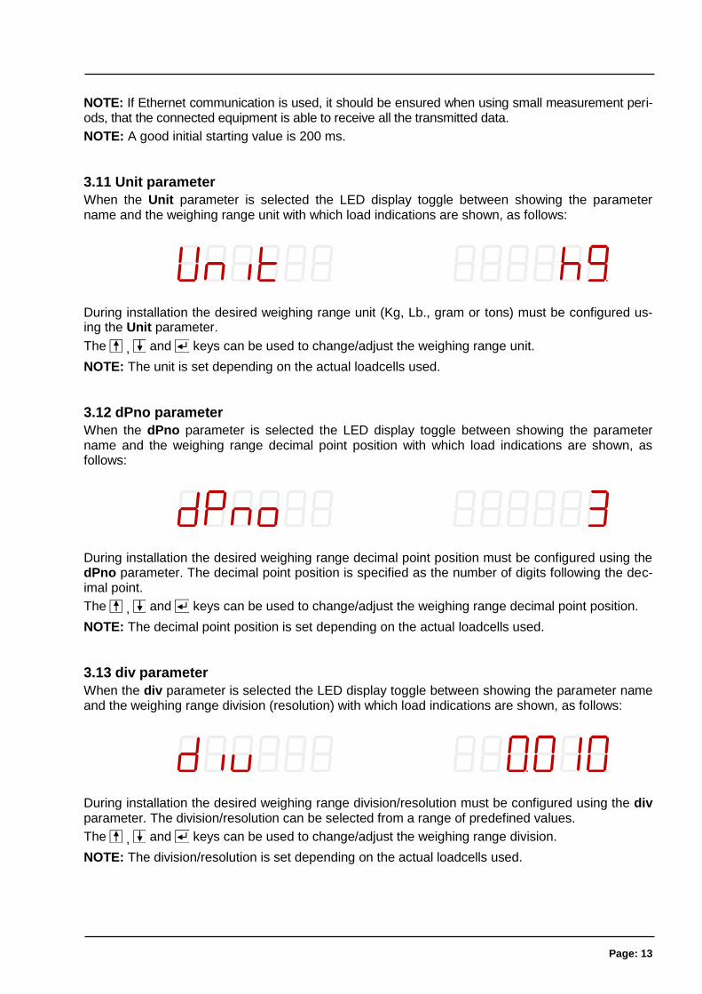
3.11 Unit parameter
When the Unit parameter is selected the LED display toggle between showing the parameter name and the weighing range unit with which load indications are shown, as follows:
During installation the desired weighing range unit (Kg, Lb., gram or tons) must be configured us-ing the Unit parameter.
The , and keys can be used to change/adjust the weighing range unit.
NOTE: The unit is set depending on the actual loadcells used.
3.12 dPno parameter
When the dPno parameter is selected the LED display toggle between showing the parameter name and the weighing range decimal point position with which load indications are shown, as follows:
During installation the desired weighing range decimal point position must be configured using the dPno parameter. The decimal point position is specified as the number of digits following the dec-imal point.
The , and keys can be used to change/adjust the weighing range decimal point position.
NOTE: The decimal point position is set depending on the actual loadcells used.
3.13 div parameter
When the div parameter is selected the LED display toggle between showing the parameter name and the weighing range division (resolution) with which load indications are shown, as follows:
During installation the desired weighing range division/resolution must be configured using the div parameter. The division/resolution can be selected from a range of predefined values.
The , and keys can be used to change/adjust the weighing range division.
NOTE: The division/resolution is set depending on the actual loadcells used.
Page: 14
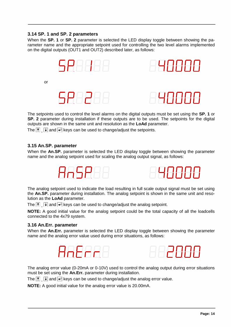
3.14 SP. 1 and SP. 2 parameters
When the SP. 1 or SP. 2 parameter is selected the LED display toggle between showing the pa-rameter name and the appropriate setpoint used for controlling the two level alarms implemented on the digital outputs (OUT1 and OUT2) described later, as follows:
or
The setpoints used to control the level alarms on the digital outputs must be set using the SP. 1 or SP. 2 parameter during installation if these outputs are to be used. The setpoints for the digital outputs are shown in the same unit and resolution as the LoAd parameter.
The , and keys can be used to change/adjust the setpoints.
3.15 An.SP. parameter
When the An.SP. parameter is selected the LED display toggle between showing the parameter name and the analog setpoint used for scaling the analog output signal, as follows:
The analog setpoint used to indicate the load resulting in full scale output signal must be set using the An.SP. parameter during installation. The analog setpoint is shown in the same unit and reso-lution as the LoAd parameter.
The , and keys can be used to change/adjust the analog setpoint.
NOTE: A good initial value for the analog setpoint could be the total capacity of all the loadcells connected to the 4x79 system.
3.16 An.Err. parameter
When the An.Err. parameter is selected the LED display toggle between showing the parameter name and the analog error value used during error situations, as follows:
The analog error value (0-20mA or 0-10V) used to control the analog output during error situations must be set using the An.Err. parameter during installation.
The , and keys can be used to change/adjust the analog error value.
NOTE: A good initial value for the analog error value is 20.00mA.
Page: 15
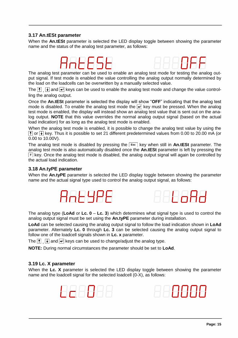
3.17 An.tESt parameter
When the An.tESt parameter is selected the LED display toggle between showing the parameter name and the status of the analog test parameter, as follows:
The analog test parameter can be used to enable an analog test mode for testing the analog out-put signal. If test mode is enabled the value controlling the analog output normally determined by the load on the loadcells can be overwritten by a manually selected value.
The , and keys can be used to enable the analog test mode and change the value control-
ling the analog output.
Once the An.tESt parameter is selected the display will show “OFF” indicating that the analog test mode is disabled. To enable the analog test mode the key must be pressed. When the analog test mode is enabled, the display will instead show an analog test value that is sent out on the ana-log output. NOTE that this value overrides the normal analog output signal (based on the actual load indication) for as long as the analog test mode is enabled.
When the analog test mode is enabled, it is possible to change the analog test value by using the or key. Thus it is possible to set 21 different predetermined values from 0.00 to 20.00 mA (or
0.00 to 10.00V).
The analog test mode is disabled by pressing the Esc key when still in An.tESt parameter. The analog test mode is also automatically disabled once the An.tESt parameter is left by pressing the
F key. Once the analog test mode is disabled, the analog output signal will again be controlled by the actual load indication.
3.18 An.tyPE parameter
When the An.tyPE parameter is selected the LED display toggle between showing the parameter name and the actual signal type used to control the analog output signal, as follows:
The analog type (LoAd or Lc. 0 – Lc. 3) which determines what signal type is used to control the analog output signal must be set using the An.tyPE parameter during installation.
LoAd can be selected causing the analog output signal to follow the load indication shown in LoAd parameter. Alternately Lc. 0 through Lc. 3 can be selected causing the analog output signal to follow one of the loadcell signals shown in Lc. x parameter.
The , and keys can be used to change/adjust the analog type.
NOTE: During normal circumstances the parameter should be set to LoAd.
3.19 Lc. X parameter
When the Lc. X parameter is selected the LED display toggle between showing the parameter name and the loadcell signal for the selected loadcell (0-X), as follows:
Page: 16
The loadcell signal (for the selected loadcell) is zeroed and shown in the same unit and resolution as the LoAd parameter.
If an error is detected (such as disconnection of the loadcell) an appropriate status code will be shown (“-XXXX-”) instead of the load indication.
The F and Esc keys can be used to switch to other parameters.
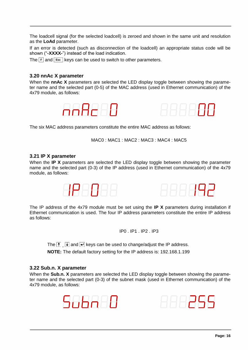
3.20 nnAc X parameter
When the nnAc X parameters are selected the LED display toggle between showing the parame-ter name and the selected part (0-5) of the MAC address (used in Ethernet communication) of the 4x79 module, as follows:
The six MAC address parameters constitute the entire MAC address as follows:
MAC0 : MAC1 : MAC2 : MAC3 : MAC4 : MAC5
3.21 IP X parameter
When the IP X parameters are selected the LED display toggle between showing the parameter name and the selected part (0-3) of the IP address (used in Ethernet communication) of the 4x79 module, as follows:
The IP address of the 4x79 module must be set using the IP X parameters during installation if Ethernet communication is used. The four IP address parameters constitute the entire IP address as follows:
IP0 . IP1 . IP2 . IP3
The , and keys can be used to change/adjust the IP address.
NOTE: The default factory setting for the IP address is: 192.168.1.199
3.22 Sub.n. X parameter
When the Sub.n. X parameters are selected the LED display toggle between showing the parame-ter name and the selected part (0-3) of the subnet mask (used in Ethernet communication) of the 4x79 module, as follows:
Page: 17
The subnet mask of the 4x79 module must be set using the Sub.n. X parameters during installa-tion if Ethernet communication is used. The four subnet mask parameters constitute the entire subnet mask as follows:
SUBN0 . SUBN1 . SUBN2 . SUBN3
The , and keys can be used to change/adjust the subnet mask.
NOTE: The default factory setting for the subnet mask is: 255.255.255.0
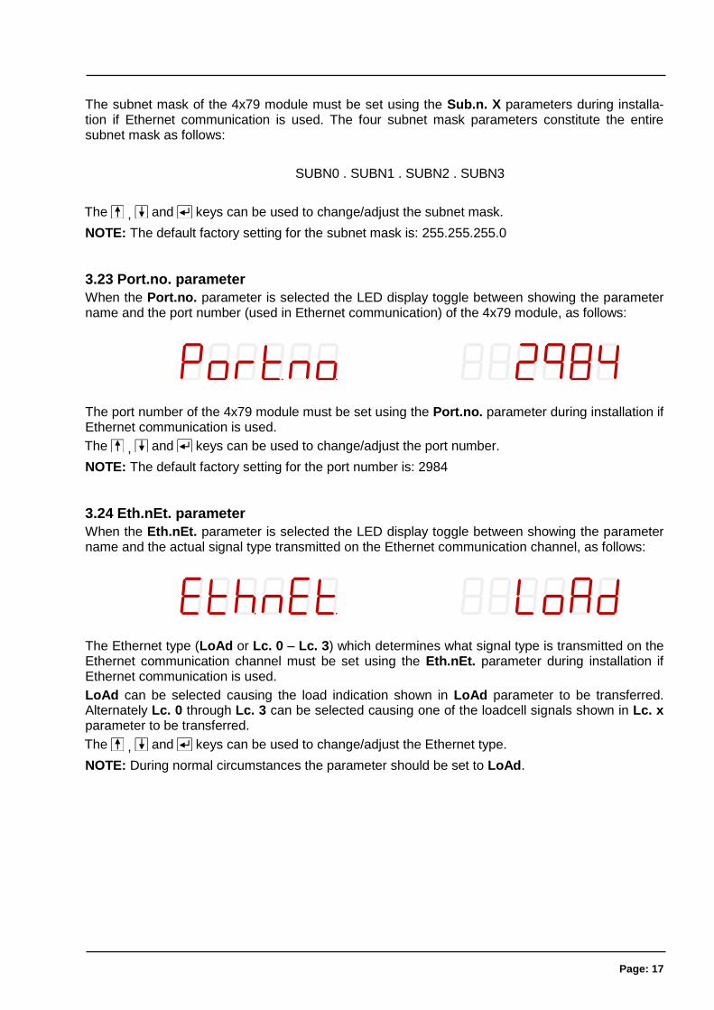
3.23 Port.no. parameter
When the Port.no. parameter is selected the LED display toggle between showing the parameter name and the port number (used in Ethernet communication) of the 4x79 module, as follows:
The port number of the 4x79 module must be set using the Port.no. parameter during installation if Ethernet communication is used.
The , and keys can be used to change/adjust the port number.
NOTE: The default factory setting for the port number is: 2984
3.24 Eth.nEt. parameter
When the Eth.nEt. parameter is selected the LED display toggle between showing the parameter name and the actual signal type transmitted on the Ethernet communication channel, as follows:
The Ethernet type (LoAd or Lc. 0 – Lc. 3) which determines what signal type is transmitted on the Ethernet communication channel must be set using the Eth.nEt. parameter during installation if Ethernet communication is used.
LoAd can be selected causing the load indication shown in LoAd parameter to be transferred. Alternately Lc. 0 through Lc. 3 can be selected causing one of the loadcell signals shown in Lc. x parameter to be transferred.
The , and keys can be used to change/adjust the Ethernet type.
NOTE: During normal circumstances the parameter should be set to LoAd.
Page: 18
3.25 Level alarms
The 2 digital outputs on the 4x79 analog module can be used as level alarms.
Setpoints for the two alarms are set using the SP. 1 or SP. 2 parameters.
The following applies to the two level alarms:
Level alarm 1:
- The alarm is implemented on the OUT1 output.
- The level of activation is selected in the SP. 1 parameter.
- The alarm is active BELOW SP1.
- The alarm is active if the status code differs from 0.
Level alarm 2:
- The alarm is implemented on the OUT2 output.
- The level of activation is selected in the SP. 2 parameter.
- The alarm is active ABOVE SP2.
- The alarm is active if the status code differs from 0.
Page: 19
3.26 Filtering
By use of DIP-switches it is possible to include one of 15 different FIR filters, that will be used to filter the load signal. Thus it is possible, to send the unfiltered weight achieved over each integra-tion period through one of the following FIR filters, before the result is displayed and send to the analog output:
SW2.4 SW2.3 SW2.2 SW2.1 Filter No.
OFF OFF OFF OFF 0
ON OFF OFF OFF 1
OFF ON OFF OFF 2
ON ON OFF OFF 3
OFF OFF ON OFF 4
ON OFF ON OFF 5
OFF ON ON OFF 6
ON ON ON OFF 7
OFF OFF OFF ON 8
ON OFF OFF ON 9
OFF ON OFF ON 10
ON ON OFF ON 11
OFF OFF ON ON 12
ON OFF ON ON 13
OFF ON ON ON 14
ON ON ON ON 15
NOTE: With all switches OFF, no filtering is performed.
The actual filter characteristics of the selected filter is shown below in Appendix E.
NOTE: The DIP-switches are only read during power-on.
Page: 20
4) Ethernet communication
This chapter describes the Ethernet communication on the RJ45/Cat5 Ethernet connector of the 4x79 analog system.
4.1 Ethernet - Specification
Protocol: TCP/IP to PC. The 4x79 module is TCP server
Communication settings 10MB/s, Half duplex
IP-Address: Fixed (default: 192.168.1.199)
TCP Port: Selectable
Ethernet connection: RJ45/Cat5
4.2 Ethernet – Data exchange
The 4x79 analog module transmits status and measured weight every measurement period on the TCP connection (Ethernet) based on what has been selected in the Eth.nEt. parameter. The result is transmitted as an ASCII string, and is only send if a client is connected to the TCP server on the 4x79 module. Only 1 TCP connection can be opened.
If LoAd is selected the contents of the transmitted telegram is:
<Status> , <Load> <LF> <CR>
If Lc. 0 through Lc. 3 is selected the contents of the transmitted telegram is:
<LcStatus[x]> , <LcSignal[x]> <LF> <CR>
where:
- <LF> is a line feed character.
- <CR> is a carriage return character.
- <Status> is the status code as shown in the LoAd parameter. This is a 4 character long hex number and should be 0000 during normal error free op-eration.
- <Load> is the gross weight as shown in the LoAd parameter. This is a 6 character long value. Note that this field will be 7 characters long if a decimal point is used.
- <LcStatus[x]> is the status code as shown in the Lc. x parameter. This is a 4 character long hex number and should be 0000 during normal error free op-eration.
- <LcSignal[x]> is the loadcell signal as shown in the Lc. x parameter. This is a 6 character long value. Note that this field will be 7 characters long if a deci-mal point is used.
4.2.1 PC Test software
The Ethernet communication can be tested with the EEOnline software. Just copy the .EXE and .INI file to a suitable location and run EEOnline.exe. Enter the IP address and the port. When then PC and the 4x79 module is on the same network segment a connection can be established by clicking “Connect”.
Page: 21
5) Hardware Description
5.1 4x79 overview
The following figure is an overview of a 4x79 analog system unit with 4 loadcell connections (i.e. a 4479 system unit):
5.2 4x79 front panel description
This chapter describes the connections, DIP-switch settings and lamp indications that are available on the front panel of the 4x79 system unit.
Page: 22
5.2.1 Connection of power
The 4x79 system unit is powered by applying +24VDC on the green two pole connectors (J6 and J3) as specified on the front panel of the 4x79 system unit. This powers the entire 4x79 system unit including the loadcells.
IMPORTANT: The used power supply must be stable and free of transients. It may therefore be necessary to use a separate power supply dedicated to the weighing system, and not connected to any other equipment.
NOTE: If the loadcells are to be placed inside an EX area, then the 4x79 system unit itself MUST be placed outside the EX area, and the 4x79 system unit MUST be supplied as follows:
1) The 2 pole connector (J3), located to the right above the 4 pole DIP-switch block, MUST be powered by a 4051A power supply (+24VDC ATEX approved) from Alfa Laval Kolding A/S.
2) The 2 pole connector (J6), located to the left “between” the display and the BNC connectors, MUST be powered by a separate +24VDC, that has NO connection to the ATEX approved +24VDC from the above mentioned 4051A power supply.
5.2.2 Connection of loadcells
The loadcells must be connected to the available BNC connectors in the front panel of the 4x79 system unit. The loadcells are connected starting with the connector marked 1 and continuing on-wards in rising order. Thus if three loadcells are to be connected, they should be connected to the BNC connectors marked 1, 2 and 3.
5.2.3 Analog output connector
The 2 pole connector (J1) located below the display on the 4x79 analog unit is used for connection of the analog output signal. Connection of the analog output signal is done as follows:
PIN NO. PIN DESIGNATION FUNCTION
1 AN. OUT Analog output
2 AN. RET Analog return
NOTE:
The analog output is an active output, and should NOT be connected to an active input.
Page: 23
5.2.4 Digital I/O connector
The 7 pole connector located below the display on the 4x79 analog unit is used for connection of the digital inputs and digital outputs. Connection of the digital inputs and digital outputs is done as follows:
PIN NO. PIN DESIGNATION FUNCTION
1 OUT1 (O1) OUT1 - Digital Output 1
Level alarm controlled by SP1. Output is active below SP1.
2 COM Common
Voltage connected to this pin (normally 24VDC) is sent to out-puts when they are active.
3 OUT2 (O2) OUT2 - Digital Output 2
Level alarm controlled by SP2. Output is active above SP2.
4 IN1 (I1) Digital Input 1 (IN1) – ZERO
Zeroing of gross weight. Must be active for at least 1 second.
Closing switch to 24VDCout.
5 GND GND
6 IN2 (I2) Digital Input 2 (IN2)
Reserved for future use – NOT connected
7 24V OUT 24VDCout
Used for activating digital inputs.
IMPORTANT: Connection of the digital I/O signals to external equipment must be made using sol-id-state-relays (SSR).
5.2.5 Ethernet connector
The front panel of the 4x79 system unit is equipped with a standard Ethernet RJ45 connector (ETHERNET) for Ethernet connection using a Cat5 cable.
5.2.6 SW1 settings
The front panel of the 4x79 system unit is equipped with a 4 pole DIP switch block named SW1. These switches are mounted on the internal 4040 communication module, and they are ONLY read during power-on. This DIP switch block has the following function when the 4040 communica-tion module is equipped with standard program:
Sw1.1 FIR Filter
OFF No filter
ON 30 taps
SWITCH FUNCTION
Sw1.2-Sw1.4 Reserved for future use
Page: 24
5.2.7 SW2 settings
The front panel of the 4x79 system unit is equipped with a 4 pole DIP switch block named SW2. These switches are ONLY read during power-on. This DIP switch block has the following function:
SWITCH FUNCTION
Sw2.1-Sw2.4 Filtering
Used to select the desired filter as described in an earlier chapter.
5.2.8 Light Emitting Diodes (LEDs)
The front panel of the 4x79 system unit is equipped with a number of status lamps (light emitting diodes). These have the following functionality:
LED FUNCTION
TXBB (left)
(Green)
4079 communication with 4040 module (internal)
4079 analog module is transmitting to 4040 module.
D1
(Yellow)
Key is pressed
A key is activated or data entry is in progress.
AE
(Red)
Analog Error
An error has been detected on the analog output. The current on the ana-log output differs from its programmed value. This may be the case if the current-loop is broken.
TxLC
(Yellow)
4040 communication with loadcells
4040 comm. module is communicating with loadcells.
TxBB (right)
(Green)
4040 comm. with 4079 analog module (internal)
4040 comm. module is transmitting to 4079 analog module.
1
(Red)
Status for loadcell 1
Bad connection, loadcell not ready or other error detected.
2
(Red)
Status for loadcell 2
Bad connection, loadcell not ready or other error detected.
3
(Red)
Status for loadcell 3
Bad connection, loadcell not ready or other error detected.
4
(Red)
Status for loadcell 4
Bad connection, loadcell not ready or other error detected.
ETHERNET
(Yellow) (RJ45)
Link (Ethernet connector)
Ethernet is connected.
ETHERNET (Green) (RJ45)
Activity (Ethernet connector)
Ethernet data is received or transmitted.
Page: 25
6) Appendices
6.1 Appendix A – Internal Features
6.1.1 4079 analog module
This chapter describes possible connections, jumper settings and LEDs that are available internally on the 4079 analog module. Jumpers will normally be set from Alfa Laval Kolding A/S and should only be changed in special situations.
6.1.2 Connectors
The 4079 analog module is internally equipped with connectors (and pin rows). These connectors have the following function:
CONNECTORS FUNCTION
J2 14 pin connector
Reserved for future direct connection of 4015 module.
J7 14 pin connector for 4040 connection
Used for connection to 4040 module for loadcell connection.
J5 JTAG connector (pin row)
Used for test purposes.
J8 UART1 connector (pin row)
This connector is used for test purposes or when downloading new software to the 4079 module using the JP12 jumper.
6.1.3 Jumper settings
The 4079 analog module is equipped with a number of internal jumpers. These jumpers have the following function:
JUMPER FUNCTION
J4 Analog output type (mA or Volt)
Jumper on pin 1-2 : mA output (normal setting from factory)
Jumper on pin 2-3 : Voltage output
JP1 Configuration jumper
Reserved for future use
JP2 Analog output type (mA or Volt)
OFF: mA output (normal setting from factory)
ON: Voltage output
JP11 Reset
The jumper allows reset of the onboard microcontroller.
OFF: Normal operation (normal setting from factory)
ON: Reset of the 4079 on-board microcontroller
JP12 BOOT Load
The jumper is used when downloading new software to the 4079 module using the J8 serial connector.
OFF: Normal power-up/operation (normal setting from factory)
ON: Download operation possible (see download description)
IMPORTANT: The placement of these should not be changed without consulting Alfa Laval Kolding A/S.
Page: 26
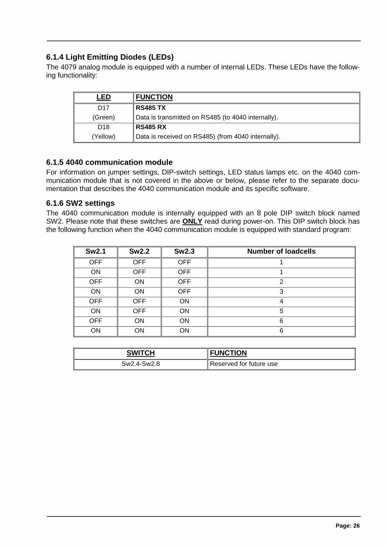
6.1.4 Light Emitting Diodes (LEDs)
The 4079 analog module is equipped with a number of internal LEDs. These LEDs have the follow-ing functionality:
LED FUNCTION
D17
(Green)
RS485 TX
Data is transmitted on RS485 (to 4040 internally).
D18
(Yellow)
RS485 RX
Data is received on RS485) (from 4040 internally).
6.1.5 4040 communication module
For information on jumper settings, DIP-switch settings, LED status lamps etc. on the 4040 com-munication module that is not covered in the above or below, please refer to the separate docu-mentation that describes the 4040 communication module and its specific software.
6.1.6 SW2 settings
The 4040 communication module is internally equipped with an 8 pole DIP switch block named SW2. Please note that these switches are ONLY read during power-on. This DIP switch block has the following function when the 4040 communication module is equipped with standard program:
Sw2.1 Sw2.2 Sw2.3 Number of loadcells
OFF OFF OFF 1
ON OFF OFF 1
OFF ON OFF 2
ON ON OFF 3
OFF OFF ON 4
ON OFF ON 5
OFF ON ON 6
ON ON ON 6
SWITCH FUNCTION
Sw2.4-Sw2.8 Reserved for future use
Page: 27
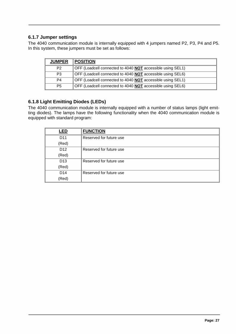
6.1.7 Jumper settings
The 4040 communication module is internally equipped with 4 jumpers named P2, P3, P4 and P5. In this system, these jumpers must be set as follows:
JUMPER POSITION
P2 OFF (Loadcell connected to 4040 NOT accessible using SEL1)
P3 OFF (Loadcell connected to 4040 NOT accessible using SEL6)
P4 OFF (Loadcell connected to 4040 NOT accessible using SEL1)
P5 OFF (Loadcell connected to 4040 NOT accessible using SEL6)
6.1.8 Light Emitting Diodes (LEDs)
The 4040 communication module is internally equipped with a number of status lamps (light emit-ting diodes). The lamps have the following functionality when the 4040 communication module is equipped with standard program:
LED FUNCTION
D11
(Red)
Reserved for future use
D12
(Red)
Reserved for future use
D13
(Red)
Reserved for future use
D14
(Red)
Reserved for future use
Page: 28
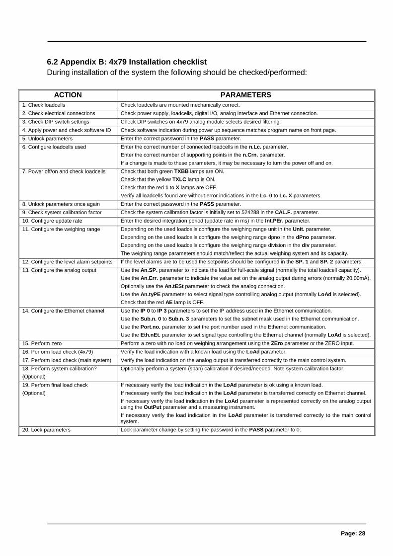
6.2 Appendix B: 4x79 Installation checklist
During installation of the system the following should be checked/performed:
ACTION PARAMETERS
1. Check loadcells Check loadcells are mounted mechanically correct.
2. Check electrical connections Check power supply, loadcells, digital I/O, analog interface and Ethernet connection.
3. Check DIP switch settings Check DIP switches on 4x79 analog module selects desired filtering.
4. Apply power and check software ID Check software indication during power up sequence matches program name on front page.
5. Unlock parameters Enter the correct password in the PASS parameter.
6. Configure loadcells used Enter the correct number of connected loadcells in the n.Lc. parameter.
Enter the correct number of supporting points in the n.Crn. parameter.
If a change is made to these parameters, it may be necessary to turn the power off and on.
7. Power off/on and check loadcells Check that both green TXBB lamps are ON.
Check that the yellow TXLC lamp is ON.
Check that the red 1 to X lamps are OFF.
Verify all loadcells found are without error indications in the Lc. 0 to Lc. X parameters.
8. Unlock parameters once again Enter the correct password in the PASS parameter.
9. Check system calibration factor Check the system calibration factor is initially set to 524288 in the CAL.F. parameter.
10. Configure update rate Enter the desired integration period (update rate in ms) in the Int.PEr. parameter.
11. Configure the weighing range Depending on the used loadcells configure the weighing range unit in the Unit. parameter.
Depending on the used loadcells configure the weighing range dpno in the dPno parameter.
Depending on the used loadcells configure the weighing range division in the div parameter.
The weighing range parameters should match/reflect the actual weighing system and its capacity.
12. Configure the level alarm setpoints If the level alarms are to be used the setpoints should be configured in the SP. 1 and SP. 2 parameters.
13. Configure the analog output Use the An.SP. parameter to indicate the load for full-scale signal (normally the total loadcell capacity).
Use the An.Err. parameter to indicate the value set on the analog output during errors (normally 20.00mA).
Optionally use the An.tESt parameter to check the analog connection.
Use the An.tyPE parameter to select signal type controlling analog output (normally LoAd is selected).
Check that the red AE lamp is OFF.
14. Configure the Ethernet channel Use the IP 0 to IP 3 parameters to set the IP address used in the Ethernet communication.
Use the Sub.n. 0 to Sub.n. 3 parameters to set the subnet mask used in the Ethernet communication.
Use the Port.no. parameter to set the port number used in the Ethernet communication.
Use the Eth.nEt. parameter to set signal type controlling the Ethernet channel (normally LoAd is selected).
15. Perform zero Perform a zero with no load on weighing arrangement using the ZEro parameter or the ZERO input.
16. Perform load check (4x79) Verify the load indication with a known load using the LoAd parameter.
17. Perform load check (main system) Verify the load indication on the analog output is transferred correctly to the main control system.
18. Perform system calibration?
(Optional)
Optionally perform a system (span) calibration if desired/needed. Note system calibration factor.
19. Perform final load check
(Optional)
If necessary verify the load indication in the LoAd parameter is ok using a known load.
If necessary verify the load indication in the LoAd parameter is transferred correctly on Ethernet channel.
If necessary verify the load indication in the LoAd parameter is represented correctly on the analog output using the OutPut parameter and a measuring instrument.
If necessary verify the load indication in the LoAd parameter is transferred correctly to the main control system.
20. Lock parameters Lock parameter change by setting the password in the PASS parameter to 0.
Page: 29
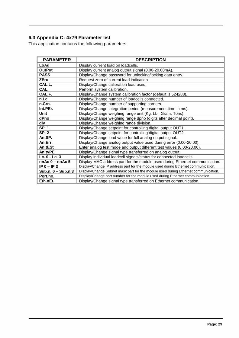
6.3 Appendix C: 4x79 Parameter list
This application contains the following parameters:
PARAMETER DESCRIPTION
LoAd Display current load on loadcells.
OutPut Display current analog output signal (0.00-20.00mA).
PASS Display/Change password for unlocking/locking data entry.
ZEro Request zero of current load indication.
CAL.L. Display/Change calibration load used.
CAL. Perform system calibration.
CAL.F. Display/Change system calibration factor (default is 524288).
n.Lc. Display/Change number of loadcells connected.
n.Crn. Display/Change number of supporting corners.
Int.PEr. Display/Change integration period (measurement time in ms).
Unit Display/Change weighing range unit (Kg, Lb., Gram, Tons).
dPno Display/Change weighing range dpno (digits after decimal point).
div Display/Change weighing range division.
SP. 1 Display/Change setpoint for controlling digital output OUT1.
SP. 2 Display/Change setpoint for controlling digital output OUT2.
An.SP. Display/Change load value for full analog output signal.
An.Err. Display/Change analog output value used during error (0.00-20.00).
An.tESt Enter analog test mode and output different test values (0.00-20.00).
An.tyPE Display/Change signal type transferred on analog output.
Lc. 0 - Lc. 3 Display individual loadcell signals/status for connected loadcells.
nnAc 0 – nnAc 5 Display MAC address part for the module used during Ethernet communication.
IP 0 – IP 3 Display/Change IP address part for the module used during Ethernet communication.
Sub.n. 0 – Sub.n.3 Display/Change Subnet mask part for the module used during Ethernet communication.
Port.no. Display/Change port number for the module used during Ethernet communication.
Eth.nEt. Display/Change signal type transferred on Ethernet communication.
Page: 30
6.4 Appendix D: Trouble shooting
6.4.1 Trouble shooting – Status code indication
If the 4x79 analog module detects a situation that results in a status code indication different from 0, the 4x79 analog module will output its error value (see An.Err. parameter) on its analog output, and the level alarms will both be active, no matter what the current load is. The actual status code will then be shown instead of the actual load in the LoAd , ZEro and CAL. parameters. It will then be possible to use the Lc. X parameter to try and locate the error.
6.4.2 Trouble shooting – Analog output error
If the build-in Digital to Analog Converter (DAC) detects an over temperature or detects that the analog output signal is different from its programmed value, then the AE light emitting diode will be lit. This will for example be the case if the current-loop is broken in a system where the module is in its current configuration.
Page: 31
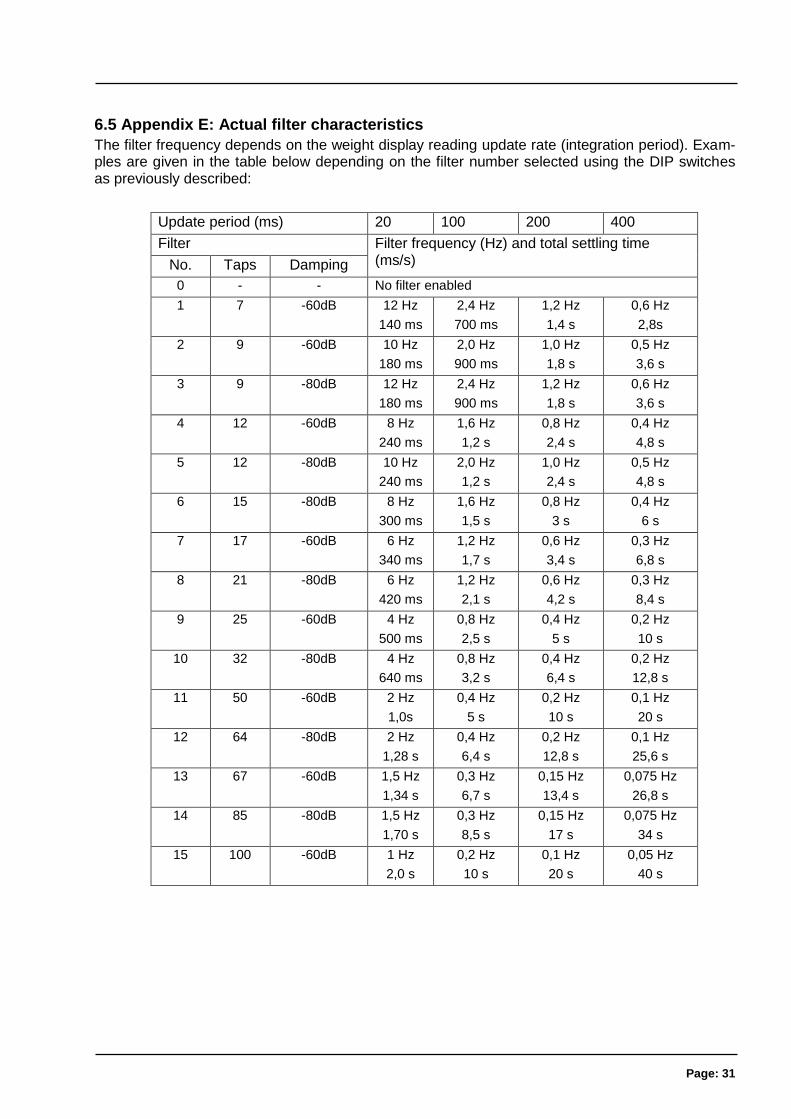
6.5 Appendix E: Actual filter characteristics
The filter frequency depends on the weight display reading update rate (integration period). Exam-ples are given in the table below depending on the filter number selected using the DIP switches as previously described:
Update period (ms) 20 100 200 400
Filter Filter frequency (Hz) and total settling time (ms/s) No. Taps Damping
0 - - No filter enabled
1 7 -60dB 12 Hz
140 ms
2,4 Hz
700 ms
1,2 Hz
1,4 s
0,6 Hz
2,8s
2 9 -60dB 10 Hz
180 ms
2,0 Hz
900 ms
1,0 Hz
1,8 s
0,5 Hz
3,6 s
3 9 -80dB 12 Hz
180 ms
2,4 Hz
900 ms
1,2 Hz
1,8 s
0,6 Hz
3,6 s
4 12 -60dB 8 Hz
240 ms
1,6 Hz
1,2 s
0,8 Hz
2,4 s
0,4 Hz
4,8 s
5 12 -80dB 10 Hz
240 ms
2,0 Hz
1,2 s
1,0 Hz
2,4 s
0,5 Hz
4,8 s
6 15 -80dB 8 Hz
300 ms
1,6 Hz
1,5 s
0,8 Hz
3 s
0,4 Hz
6 s
7 17 -60dB 6 Hz
340 ms
1,2 Hz
1,7 s
0,6 Hz
3,4 s
0,3 Hz
6,8 s
8 21 -80dB 6 Hz
420 ms
1,2 Hz
2,1 s
0,6 Hz
4,2 s
0,3 Hz
8,4 s
9 25 -60dB 4 Hz
500 ms
0,8 Hz
2,5 s
0,4 Hz
5 s
0,2 Hz
10 s
10 32 -80dB 4 Hz
640 ms
0,8 Hz
3,2 s
0,4 Hz
6,4 s
0,2 Hz
12,8 s
11 50 -60dB 2 Hz
1,0s
0,4 Hz
5 s
0,2 Hz
10 s
0,1 Hz
20 s
12 64 -80dB 2 Hz
1,28 s
0,4 Hz
6,4 s
0,2 Hz
12,8 s
0,1 Hz
25,6 s
13 67 -60dB 1,5 Hz
1,34 s
0,3 Hz
6,7 s
0,15 Hz
13,4 s
0,075 Hz
26,8 s
14 85 -80dB 1,5 Hz
1,70 s
0,3 Hz
8,5 s
0,15 Hz
17 s
0,075 Hz
34 s
15 100 -60dB 1 Hz
2,0 s
0,2 Hz
10 s
0,1 Hz
20 s
0,05 Hz
40 s
Page: 32
6.6 Appendix F – Status Codes
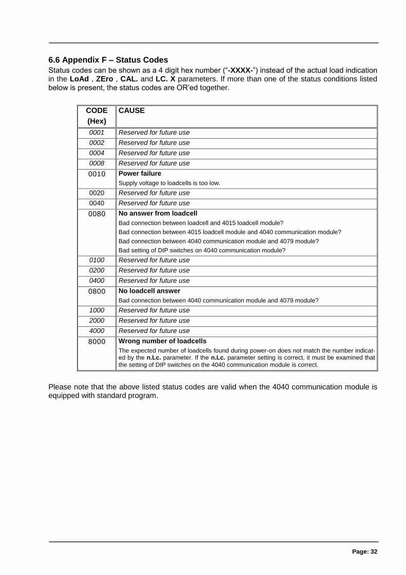
Status codes can be shown as a 4 digit hex number (“-XXXX-”) instead of the actual load indication in the LoAd , ZEro , CAL. and LC. X parameters. If more than one of the status conditions listed below is present, the status codes are OR’ed together.
CODE
(Hex)
CAUSE
0001 Reserved for future use
0002 Reserved for future use
0004 Reserved for future use
0008 Reserved for future use
0010 Power failure
Supply voltage to loadcells is too low.
0020 Reserved for future use
0040 Reserved for future use
0080 No answer from loadcell
Bad connection between loadcell and 4015 loadcell module?
Bad connection between 4015 loadcell module and 4040 communication module?
Bad connection between 4040 communication module and 4079 module?
Bad setting of DIP switches on 4040 communication module?
0100 Reserved for future use
0200 Reserved for future use
0400 Reserved for future use
0800 No loadcell answer
Bad connection between 4040 communication module and 4079 module?
1000 Reserved for future use
2000 Reserved for future use
4000 Reserved for future use
8000 Wrong number of loadcells
The expected number of loadcells found during power-on does not match the number indicat-ed by the n.Lc. parameter. If the n.Lc. parameter setting is correct, it must be examined that
the setting of DIP switches on the 4040 communication module is correct.
Please note that the above listed status codes are valid when the 4040 communication module is equipped with standard program.
Page: 33
7) How to contact Alfa Laval Kolding A/S
For further information please feel free to contact: Alfa Laval Kolding A/S
31, Albuen - DK 6000 Kolding - Denmark
Registration number: 30938011
Tel switchboard: +45 79 32 22 00 - Fax switchboard: +45 79 32 25 80
www.alfalaval.com - [email protected]
Contact details for all countries are continually updated on our websites.

Page: 34
8) EC Declaration of Conformity
EC Declaration of Conformity
The designated company Alfa Laval Kolding A/S Company name
Albuen 31, 6000 Kolding, Denmark Address
+ +45 79 32 22 00 Phone no.
hereby declare that
Alfa Laval ANALOG SYSTEM TEXXXXXXXXXXXX Denomination Type
valid for serial numbers from 2017-00001 and subsequent serial numbers.
is in conformity with the provisions of the Directive 73/23/EEC appendix IIIB and directive 89/356/EEC. And furthermore declares that the following (parts/clauses of) applicable directives have been used: - EN 61010 Part 1 (Safety requirements for electrical equipment for measurements control and laboratory use) - EN 60529 (degrees of protection provided by enclosures) - EN50081 part 1 (EMC, generic emission standard) - 50082 part 2 (EMC, generic immunity standard)
Global Product Quality Manager Pumps, Valves, Fittings and Tank Equipment Lars Kruse Andersen
Title Name Signature
August 1, 2017 Kolding Date Place


![Alfa Laval Culturefuge 400 B · Alfa Laval is a trademark registered and owned by Alfa Laval Corporate AB. [Product name] is a trademark owned by Alfa Laval Corporate AB. PCHS00142EN](https://img.pdfslide.us/doc/110x75/5e71a377bc5a292f26773958/alfa-laval-culturefuge-400-b-alfa-laval-is-a-trademark-registered-and-owned-by-alfa.jpg)