Embed Size (px)
Citation preview
TS02-0345
INSTRUCTION MANUAL
FOR
CAPACITIVE LEVEL SENSOR
MODEL: CG-□□□□□□K
Issued 2014-06-02
- ADD 1 -
Read and unders tand th is manual for safe usage.
・ This manual descr ibes the product of standard specif icat ion. Read the other
manual for the product of explosion-proof specif icat ion.
・ This manual descr ibes the handl ing, inspect ion and adjustment of the product
whose model is ment ioned on the cover page. Read and understand this
manual before handl ing.
・ Follow the addit ional document and/or direct ion, submit ted by NOHKEN INC.
and our distr ibutor or agent, even if the terms are ment ioned in this manual.
・ Save this manual in a proper place being avai lable to refer to immediately.
・ The specif icat ion of product ment ioned in this manual may not be sat isf ied by
the condit ion of environment and usage. Check and consider careful ly before
using.
・ Contact to sales of f ice at NOHKEN INC. for any quest ion or comment about
this manual and product .
The fol lowing are the descr ipt ion of the terms in this manual.
WARNINGIndicates a potential ly hazardous situat ion which, if not
paid attent ion to, could result in death, serious injury or
serious disaster.
CAUTIONIndicates a hazardous situat ion which, if not paid
attention to, may result in minor or moderate injury
or damage to the device.
Indicates a prohibited matter.
The explanation with this mark shal l be followed.
Indicates an instructed matter.
The explanation with this mark shal l be followed.
- ADD 2 -
WARNINGThis product is not explosion-proof construct ion. Do not instal l this
product to the place where the f lammable gas or vapor occurs.
I f instal led, the f lammable gas or vapor may be ignited, and
serious disaster may occur. Use the product of explosion-proof
construct ion in this case.
Do not modify or disassemble the product. Otherwise, the product
and connected device may be malfunctioned, damaged, f ired, or
minor injury and electr ic shock may occur.
(Fol low the addit ional document and/or direct ion, submitted by
NOHKEN INC. and our distr ibutor or agent.)
Turn off the power, before wir ing and inspection.
Otherwise, electr ic leakage, f ire caused by short circuit , and
electr ic shock may occur.
Ensure the wire is proper ly connected. The product and connected
device may be malfunctioned, damaged, f ired, or minor injury and
electr ic shock may occur by improper wir ing.
Turn off the power immediately, if the smoke, strange smell and
sound occur. Do not use it unti l the problem is solved.
CAUTIONAvoid strong shock and rough handl ing to this product.
The product may be damaged by strong shock such as
dropping, fall ing, throwing, knocking, lugging, etc.
Fol low the specif icat ion of operat ing temperature, operat ing
pressure, switch rat ing, etc. Otherwise, the product and connected
device may be malfunctioned, damaged, f ired, or minor injury and
electr ic shock may occur. Check the manual or specif icat ion sheet.
Operation test shal l be done before pract ical usage. If the serious
accident is expected to occur by malfunct ion of the product,
the other operat ing principle of product shal l be instal led in paral lel.
- ADD 3 -
CAUTION
Check and deeply consider the chemical compatibi l i ty for the
material of product in advance.
Hold the stem very close to the mount ing point, when carrying,
instal l ing, and removing. If held by the housing, it may be
taken off f rom the f lange or plug, and the product may be damaged
by dropping.
The product is 50cm or longer
The product shal l be kept horizontal ly. The product and other
goods could be damaged, and minor injury may occur by fall ing.
Earth terminal shall be grounded to JIS Class D ground (earth
resistance less than 100Ω). I f not grounded, electr ic shock may
occur by any accident.
In case of connect ing inductive or lamp load to the product.
Provide protect ive circuit to the load to avoid over voltage and
over current. I f not provided, the contact may be damaged.
Provide arrester or surge absorber to avoid electr ical impact such
as l ightning and stat ic electr ic ity. I f not provided, the product and
connected device may be malfunct ioned, damaged, and f ired, or
minor injury and electr ic shock may occur.
- ADD 4 -
INTRODUCTION
A) This manual specif ies the specif ication of a general product.
If you order a special product, some details of specif ication may be
dif ferent with the manual.
B) We are glad to suggest and advise for Model selection and chemical
resistance of material, but f inal decision has to be made by the customer.
C) This manual has been prepared with close attention. Ask sales off ice at
NOHKEN INC. for any question or comment about the contents of this
manual.
D) For replacement parts
The quality of product has frequently improved, so same spare parts may
not be supplied. In this case, replacement parts or products may be
supplied. Ask sales off ice at NOHKEN INC. for detai ls.
E) The contents of this manual are subject to change any time without notice
due to the improvement of the product.
WARRANTY & DISCLAIMER
A) NOHKEN INC. warrants this product against defect in design, material and
workmanship for a period of 1(one) year from the date of original factory
shipment.
B) The warranty only covers the damage of products. The secondary and
third kind disasters are not covered by NOHKEN INC.
C) NOHKEN INC. shall not be liable for the following.
C-a) Do not follow the description and direction in this manual.
C-b) Damage due to improper installat ion, wiring, usage, maintenance,
inspection, storing, etc.
C-c) Repair and modif ication are done by the person who is not an
employee of NOHKEN INC. and our distr ibutor or agent.
C-d) Improper parts are used and replaced.
C-e) The damage is occurred by the device or machine except our
products.
C-f) Improper usage. (See "Purpose of use" in chapter 1 in this manual)
C-g) Force Majeure including, but not l imited to, f ire, earthquake, tsunami,
l ightning, riots, revolution, war, radioactive pollut ion, acts of God,
acts of government or governmental authorit ies, compliance with law,
regulat ion, and order.
THE TERMS OF WARRANTY AND DISCLAIMER SHALL IN NO WAY LIMIT
YOUR LEGAL RIGHTS.
Table of Contents
1.PURPOSE OF USE …………………………………………… 1
2.DESCRIPTION …………………………………………… 1
2.1 Description …………………………………………… 1
2.2 Principle of operation …………………………………………… 1
3.SPECIFICATIONS …………………………………………… 2
3.1 Part names and functions …………………………………………… 2
3.2 Model numbering …………………………………………… 3
3.3 Specification …………………………………………… 4
4.HANDLING NOTES …………………………………………… 5
5.INSTALLATION …………………………………………… 6
5.1 Unpacking …………………………………………… 6
5.2 Mounting …………………………………………… 7
5.2.1 Mounting location …………………………………………… 7
5.2.2 Mounting the sensor …………………………………………… 10
5.2.3 Mounting orientation …………………………………………… 10
5.3 Mutual interference …………………………………………… 11
6.WIRING …………………………………………… 12
6.1 Before wiring …………………………………………… 12
6.2 Wiring …………………………………………… 12
6.3 Cable inlet …………………………………………… 13
6.4 Placing the cover …………………………………………… 13
7.ADJUSTMENT …………………………………………… 14
7.1 Before adjustment …………………………………………… 14
7.2 Key operation during adjustment …………………………………………… 16
7.3 Parameters …………………………………………… 17
7.4 Sensitivity setting (Zero / Span setting) …………………………………… 19
7.5 Setting alarm …………………………………………… 25
7.5.1 OFF-ON setting …………………………………………… 25
7.5.2 OFF timer and ON timer setting …………………………………………… 28
7.5.3 Setting relay …………………………………………… 31
7.5.4 Display setting …………………………………………… 33
7.5.5 Alarm check …………………………………………… 35
7.6 Deactivating the warning …………………………………………… 37
7.7 Parameter list …………………………………………… 38
8.MAINTENANCE AND INSPECTION ……………………… 39
8.1 Maintenance procedure …………………………………………… 39
8.2 When to replace the sensor …………………………………………… 39
9.STORING …………………………………………… 40
10.TROUBLE SHOOTING …………………………………………… 41
11.GLOSSARY …………………………………………… 42
- 1 -
1. PURPOSE OF USECapacitive Level Sensor CG is a level instrument to detect presence of liquids
or solids to send signals utilized to give an alarm output or control output for
pump or other devices. Do not use for any other purpose.
2. DESCRIPTION2.1 Description
CG sensor is mounted on a tank using the threaded connection(*) or flange(*).
Its electrode inserted into a tank detects a level of liquids or solids.
The electrode has no moving parts to achieve a long service life. The sensor
incorporates a special circuit that can minimize buildup affection,
semiconductor damage or faulty operation caused by high voltage static
electricity in solids.
Adjustment is easily made without need for a tester or other devices.
2.2 Principle of operation
The CG sensor, mounted on a tank, forms a capacitor(*) between its electrode and
the tank wall. The capacitance(*) of this capacitor is proportional to the
dielectric constant of the material inside the tank. The capacitor and the coil
in the sensor circuit form a parallel circuit, which resonates at a frequency
when an alternating signal is given. The resonation can be maintained by
detecting the phase of the parallel circuit and then automatically adjusting
the frequency to create the same phase. Thus the sensor utilizes change in
frequency to determine material presence, enabling a wide range of sensitivity
settings, from high to low values. Material resistance has no effect on the
resonance frequency, so the buildup affection is minimized regardless of the
sensitivity setting.
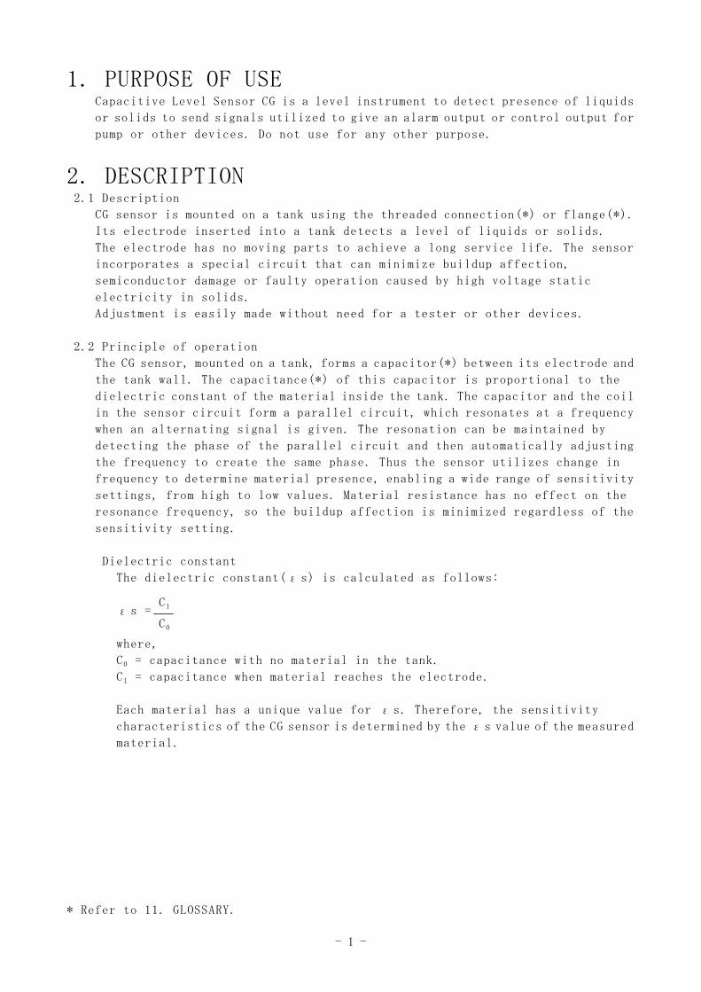
Dielectric constant
The dielectric constant(εs) is calculated as follows:
εs =
where,
C0 = capacitance with no material in the tank.
C1 = capacitance when material reaches the electrode.
Each material has a unique value for εs. Therefore, the sensitivity
characteristics of the CG sensor is determined by the εs value of the measured
material.
* Refer to 11. GLOSSARY.
C0
C1
- 2 -
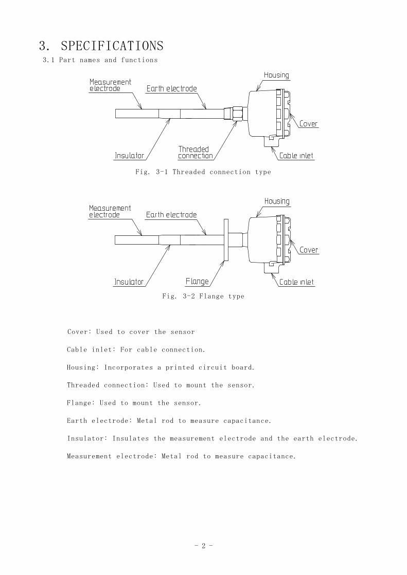
3. SPECIFICATIONS3.1 Part names and functions
Fig. 3-1 Threaded connection type
Fig. 3-2 Flange type
Cover: Used to cover the sensor
Cable inlet: For cable connection.
Housing: Incorporates a printed circuit board.
Threaded connection: Used to mount the sensor.
Flange: Used to mount the sensor.
Earth electrode: Metal rod to measure capacitance.
Insulator: Insulates the measurement electrode and the earth electrode.
Measurement electrode: Metal rod to measure capacitance.
- 3 -
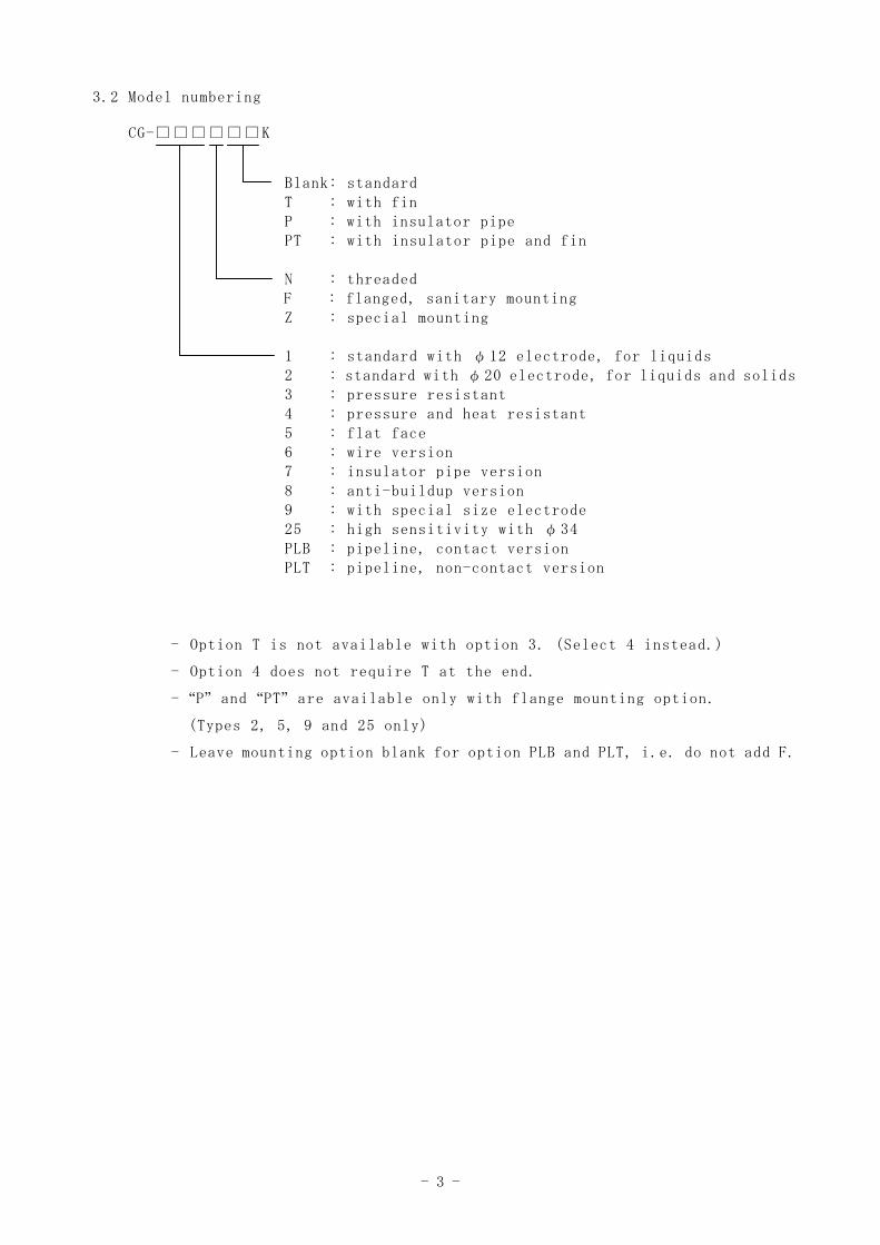
3.2 Model numbering
CG-□□□□□□K
Blank: standardT : with finP : with insulator pipePT : with insulator pipe and fin
N : threadedF : flanged, sanitary mountingZ : special mounting
1 : standard with φ12 electrode, for liquids2 : standard with φ20 electrode, for liquids and solids3 : pressure resistant4 : pressure and heat resistant5 : flat face6 : wire version7 : insulator pipe version8 : anti-buildup version9 : with special size electrode25 : high sensitivity with φ34PLB : pipeline, contact versionPLT : pipeline, non-contact version
- Option T is not available with option 3. (Select 4 instead.)
- Option 4 does not require T at the end.
- “P” and “PT” are available only with flange mounting option.
(Types 2, 5, 9 and 25 only)
- Leave mounting option blank for option PLB and PLT, i.e. do not add F.
- 4 -
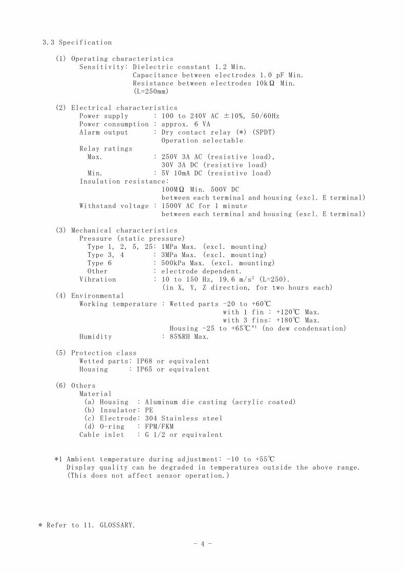
3.3 Specification
(1) Operating characteristicsSensitivity: Dielectric constant 1.2 Min.
Capacitance between electrodes 1.0 pF Min.Resistance between electrodes 10kΩ Min.(L=250mm)
(2) Electrical characteristicsPower supply : 100 to 240V AC ±10%, 50/60HzPower consumption : approx. 6 VAAlarm output : Dry contact relay (*) (SPDT)
Operation selectableRelay ratings
Max. : 250V 3A AC (resistive load),30V 3A DC (resistive load)
Min. : 5V 10mA DC (resistive load)Insulation resistance:
100MΩ Min. 500V DCbetween each terminal and housing (excl. E terminal)
Withstand voltage : 1500V AC for 1 minutebetween each terminal and housing (excl. E terminal)
(3) Mechanical characteristicsPressure (static pressure)
Type 1, 2, 5, 25: 1MPa Max. (excl. mounting)Type 3, 4 : 3MPa Max. (excl. mounting)Type 6 : 500kPa Max. (excl. mounting)Other : electrode dependent.
Vibration : 10 to 150 Hz, 19.6 m/s2 (L=250).(in X, Y, Z direction, for two hours each)
(4) EnvironmentalWorking temperature : Wetted parts -20 to +60℃
with 1 fin : +120℃ Max.with 3 fins: +180℃ Max.
Housing -25 to +65℃ *1 (no dew condensation)Humidity : 85%RH Max.
(5) Protection classWetted parts: IP68 or equivalentHousing : IP65 or equivalent
(6) OthersMaterial(a) Housing : Aluminum die casting (acrylic coated)(b) Insulator: PE(c) Electrode: 304 Stainless steel(d) O-ring : FPM/FKM
Cable inlet : G 1/2 or equivalent
*1 Ambient temperature during adjustment: -10 to +55℃Display quality can be degraded in temperatures outside the above range.(This does not affect sensor operation.)
* Refer to 11. GLOSSARY.
- 5 -
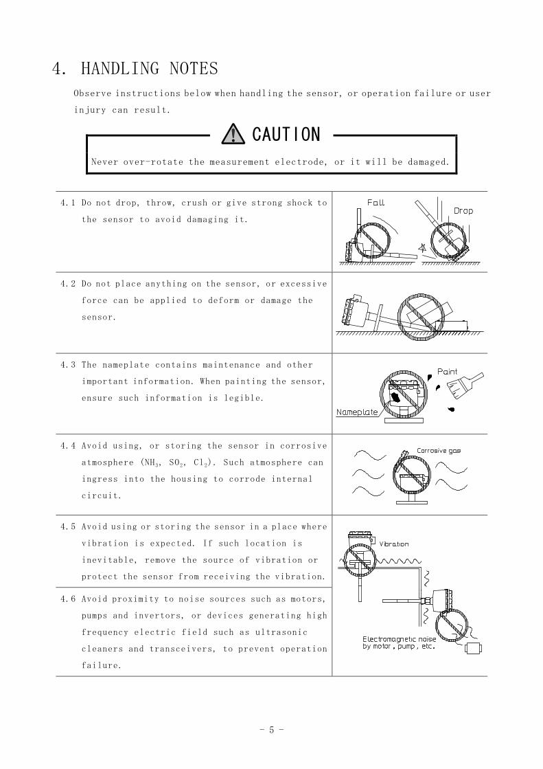
4. HANDLING NOTESObserve instructions below when handling the sensor, or operation failure or user
injury can result.
CAUTION
Never over-rotate the measurement electrode, or it will be damaged.
4.1 Do not drop, throw, crush or give strong shock to
the sensor to avoid damaging it.
4.2 Do not place anything on the sensor, or excessive
force can be applied to deform or damage the
sensor.
4.3 The nameplate contains maintenance and other
important information. When painting the sensor,
ensure such information is legible.
4.4 Avoid using, or storing the sensor in corrosive
atmosphere (NH3, SO2, Cl2). Such atmosphere can
ingress into the housing to corrode internal
circuit.
4.5 Avoid using or storing the sensor in a place where
vibration is expected. If such location is
inevitable, remove the source of vibration or
protect the sensor from receiving the vibration.
4.6 Avoid proximity to noise sources such as motors,
pumps and invertors, or devices generating high
frequency electric field such as ultrasonic
cleaners and transceivers, to prevent operation
failure.
- 6 -
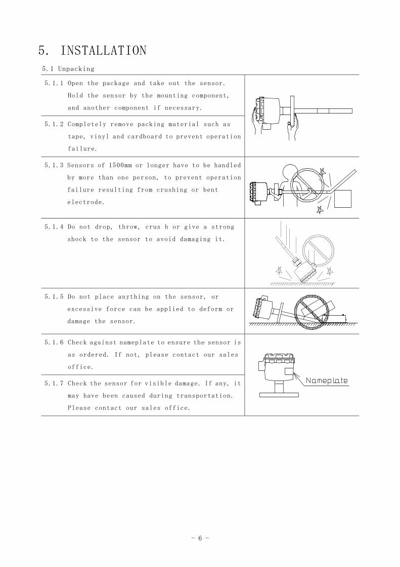
5. INSTALLATION5.1 Unpacking
5.1.1 Open the package and take out the sensor.
Hold the sensor by the mounting component,
and another component if necessary.
5.1.2 Completely remove packing material such as
tape, vinyl and cardboard to prevent operation
failure.
5.1.3 Sensors of 1500mm or longer have to be handled
by more than one person, to prevent operation
failure resulting from crushing or bent
electrode.
5.1.4 Do not drop, throw, crus h or give a strong
shock to the sensor to avoid damaging it.
5.1.5 Do not place anything on the sensor, or
excessive force can be applied to deform or
damage the sensor.
5.1.6 Check against nameplate to ensure the sensor is
as ordered. If not, please contact our sales
office.
5.1.7 Check the sensor for visible damage. If any, it
may have been caused during transportation.
Please contact our sales office.
- 7 -
5.2 Mounting
5.2.1 Mounting location
When mounting, observe the following instructions.
Failure to do so can result in operation failure.
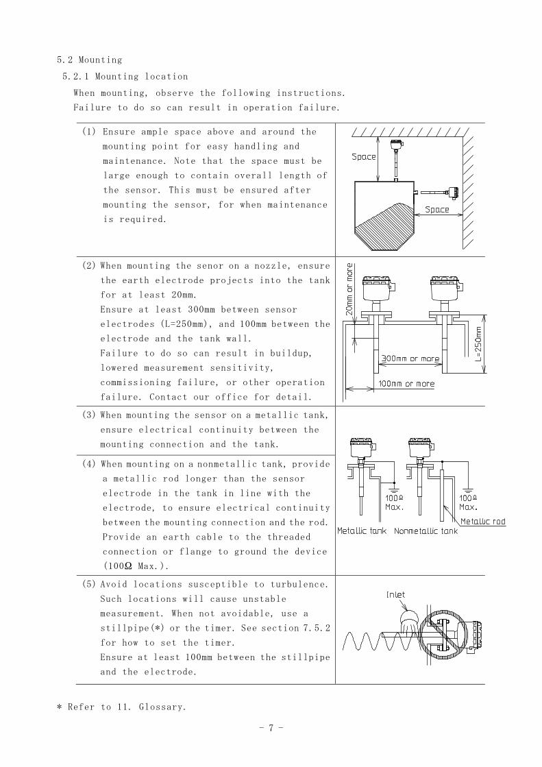
(1) Ensure ample space above and around the
mounting point for easy handling and
maintenance. Note that the space must be
large enough to contain overall length of
the sensor. This must be ensured after
mounting the sensor, for when maintenance
is required.
(2) When mounting the senor on a nozzle, ensure
the earth electrode projects into the tank
for at least 20mm.
Ensure at least 300mm between sensor
electrodes (L=250mm), and 100mm between the
electrode and the tank wall.
Failure to do so can result in buildup,
lowered measurement sensitivity,
commissioning failure, or other operation
failure. Contact our office for detail.
(3) When mounting the sensor on a metallic tank,
ensure electrical continuity between the
mounting connection and the tank.
(4) When mounting on a nonmetallic tank, provide
a metallic rod longer than the sensor
electrode in the tank in line with the
electrode, to ensure electrical continuity
between the mounting connection and the rod.
Provide an earth cable to the threaded
connection or flange to ground the device
(100Ω Max.).
(5) Avoid locations susceptible to turbulence.
Such locations will cause unstable
measurement. When not avoidable, use a
stillpipe(*) or the timer. See section 7.5.2
for how to set the timer.
Ensure at least 100mm between the stillpipe
and the electrode.
* Refer to 11. Glossary.
- 8 -
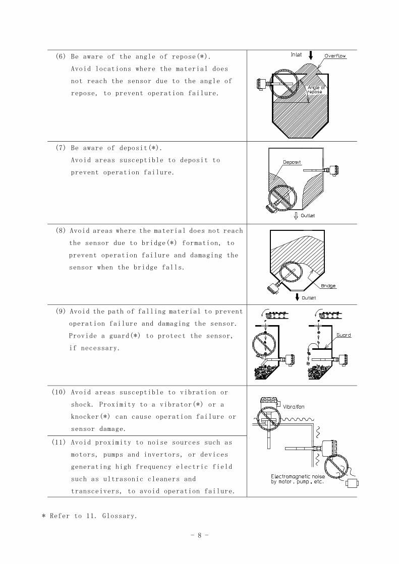
(6) Be aware of the angle of repose(*).
Avoid locations where the material does
not reach the sensor due to the angle of
repose, to prevent operation failure.
(7) Be aware of deposit(*).
Avoid areas susceptible to deposit to
prevent operation failure.
(8) Avoid areas where the material does not reach
the sensor due to bridge(*) formation, to
prevent operation failure and damaging the
sensor when the bridge falls.
(9) Avoid the path of falling material to prevent
operation failure and damaging the sensor.
Provide a guard(*) to protect the sensor,
if necessary.
(10) Avoid areas susceptible to vibration or
shock. Proximity to a vibrator(*) or a
knocker(*) can cause operation failure or
sensor damage.
(11) Avoid proximity to noise sources such as
motors, pumps and invertors, or devices
generating high frequency electric field
such as ultrasonic cleaners and
transceivers, to avoid operation failure.
* Refer to 11. Glossary.
- 9 -
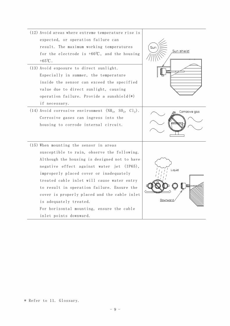
(12) Avoid areas where extreme temperature rise is
expected, or operation failure can
result. The maximum working temperatures
for the electrode is +60℃, and the housing
+65℃.
(13) Avoid exposure to direct sunlight.
Especially in summer, the temperature
inside the sensor can exceed the specified
value due to direct sunlight, causing
operation failure. Provide a sunshield(*)
if necessary.
(14) Avoid corrosive environment (NH3, SO2, Cl2).
Corrosive gases can ingress into the
housing to corrode internal circuit.
(15) When mounting the sensor in areas
susceptible to rain, observe the following.
Although the housing is designed not to have
negative effect against water jet (IP65),
improperly placed cover or inadequately
treated cable inlet will cause water entry
to result in operation failure. Ensure the
cover is properly placed and the cable inlet
is adequately treated.
For horizontal mounting, ensure the cable
inlet points downward.
* Refer to 11. Glossary.
- 10 -
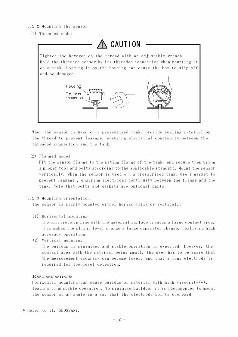
5.2.2 Mounting the sensor
(1) Threaded model
CAUTION
Tighten the hexagon on the thread with an adjustable wrench.
Hold the threaded sensor by its threaded connection when mounting it
on a tank. Holding it by the housing can cause the box to slip off
and be damaged.
When the sensor is used on a pressurized tank, provide sealing material on
the thread to prevent leakage, ensuring electrical continuity between the
threaded connection and the tank.
(2) Flanged model
Fit the sensor flange to the mating flange of the tank, and secure them using
a proper tool and bolts according to the applicable standard. Mount the sensor
vertically. When the sensor is used o n a pressurized tank, use a gasket to
prevent leakage , ensuring electrical continuity between the flange and the
tank. Note that bolts and gaskets are optional parts.
5.2.3 Mounting orientation
The sensor is mainly mounted either horizontally or vertically.
(1) Horizontal mounting
The electrode in line with the material surface creates a large contact area.
This makes the slight level change a large capacitor change, realizing high
accuracy operation.
(2) Vertical mounting
The buildup is minimized and stable operation is expected. However, the
contact area with the material being small, the user has to be aware that
the measurement accuracy can become lower, and that a long electrode is
required for low level detection.
Reference
Horizontal mounting can cause buildup of material with high viscosity(*),
leading to unstable operation. To minimize buildup, it is recommended to mount
the sensor at an angle in a way that the electrode points downward.
* Refer to 11. GLOSSARY.
- 11 -
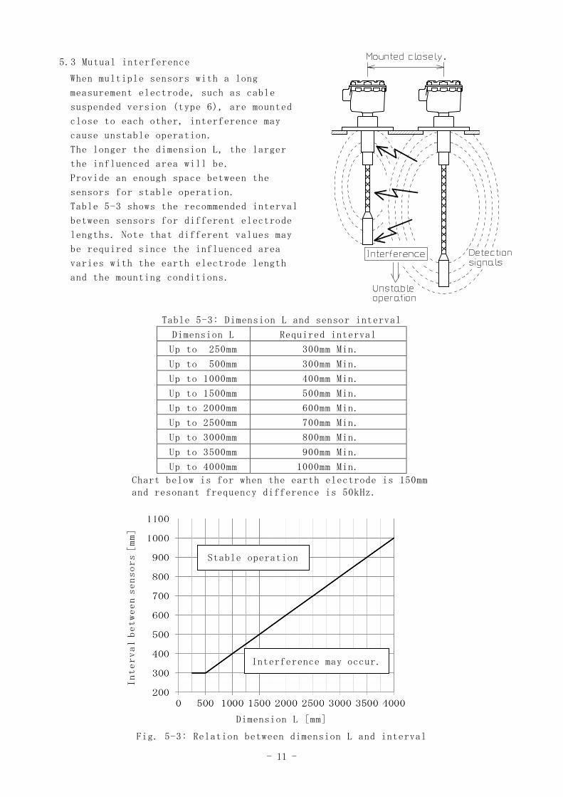
5.3 Mutual interference
When multiple sensors with a long
measurement electrode, such as cable
suspended version (type 6), are mounted
close to each other, interference may
cause unstable operation.
The longer the dimension L, the larger
the influenced area will be.
Provide an enough space between the
sensors for stable operation.
Table 5-3 shows the recommended interval
between sensors for different electrode
lengths. Note that different values may
be required since the influenced area
varies with the earth electrode length
and the mounting conditions.
Table 5-3: Dimension L and sensor interval
Dimension L Required interval
Up to 250mm 300mm Min.
Up to 500mm 300mm Min.
Up to 1000mm 400mm Min.
Up to 1500mm 500mm Min.
Up to 2000mm 600mm Min.
Up to 2500mm 700mm Min.
Up to 3000mm 800mm Min.
Up to 3500mm 900mm Min.
Up to 4000mm 1000mm Min.
Chart below is for when the earth electrode is 150mmand resonant frequency difference is 50kHz.
Dimension L [mm]
Fig. 5-3: Relation between dimension L and interval
Stable operation
Interference may occur.
Intervalbetweensensors[mm]
- 12 -
6. WIRING6.1 Before wiring
6.1.1 Disconnect power.
WARNINGDisconnect power before wiring, or electric shock, leakage, ignition
or user injury due to short circuit can result.
CAUTIONContact ratings are 250V, 3A AC (resistive load) or 30V, 3A DC
(resistive load). Ensure the connected load is within these ratings,
or the relay contacts can be damaged. If the load exceeds the ratings,
use another relay or a device suitable for the load, between the load
and the output terminal of the sensor.
6.1.2 Remove the cover of the housing.
6.2 Wiring
Connect cable to each terminal. Use a tool to tighten the screws. Terminal screws
are of M4, so use a cable lug of R1.25-4 or an equivalent size.
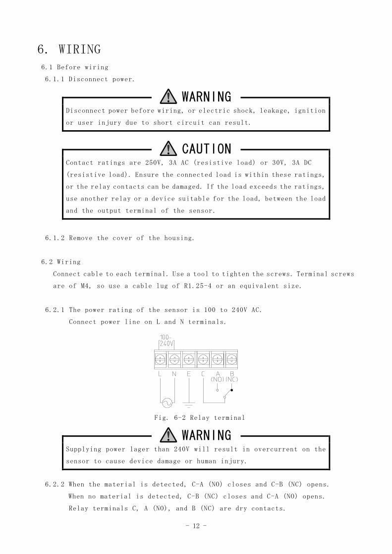
6.2.1 The power rating of the sensor is 100 to 240V AC.
Connect power line on L and N terminals.
Fig. 6-2 Relay terminal
WARNINGSupplying power lager than 240V will result in overcurrent on the
sensor to cause device damage or human injury.
6.2.2 When the material is detected, C-A (NO) closes and C-B (NC) opens.
When no material is detected, C-B (NC) closes and C-A (NO) opens.
Relay terminals C, A (NO), and B (NC) are dry contacts.
- 13 -
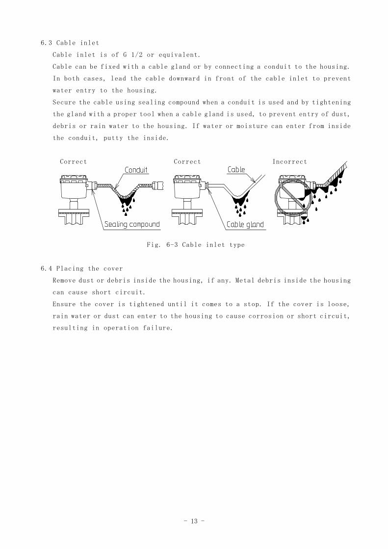
6.3 Cable inlet
Cable inlet is of G 1/2 or equivalent.
Cable can be fixed with a cable gland or by connecting a conduit to the housing.
In both cases, lead the cable downward in front of the cable inlet to prevent
water entry to the housing.
Secure the cable using sealing compound when a conduit is used and by tightening
the gland with a proper tool when a cable gland is used, to prevent entry of dust,
debris or rain water to the housing. If water or moisture can enter from inside
the conduit, putty the inside.
Correct Correct Incorrect
Fig. 6-3 Cable inlet type
6.4 Placing the cover
Remove dust or debris inside the housing, if any. Metal debris inside the housing
can cause short circuit.
Ensure the cover is tightened until it comes to a stop. If the cover is loose,
rain water or dust can enter to the housing to cause corrosion or short circuit,
resulting in operation failure.
- 14 -
7. ADJUSTMENTThe sensor is factory calibrated to suit your application. However, operation
can become unstable depending on conditions in the tank, or due to change of
mounting or in material, and buildup affection. In these cases, make adjustment
following steps in section 7.4 Sensitivity adjustment.
For other programming procedures, such as delay time and relay operation settings,
see section 7.5.
If the sensor displays “ER”, then follow the steps in 7.6.
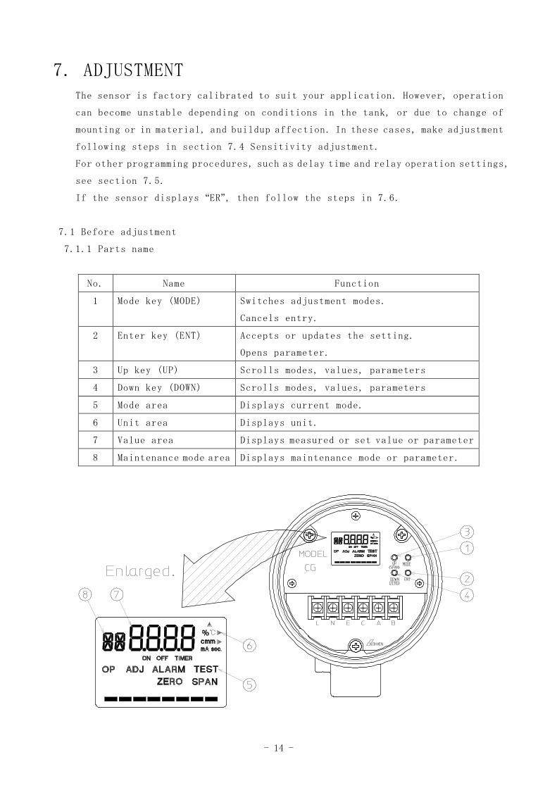
7.1 Before adjustment
7.1.1 Parts name
No. Name Function
1 Mode key (MODE) Switches adjustment modes.
Cancels entry.
2 Enter key (ENT) Accepts or updates the setting.
Opens parameter.
3 Up key (UP) Scrolls modes, values, parameters
4 Down key (DOWN) Scrolls modes, values, parameters
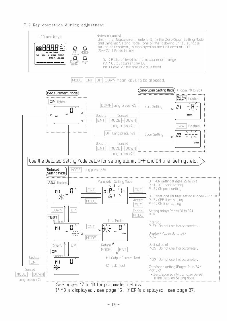
5 Mode area Displays current mode.
6 Unit area Displays unit.
7 Value area Displays measured or set value or parameter
8 Maintenance mode area Displays maintenance mode or parameter.
- 15 -
7.1.2 Supplying power
Supply power to the sensor.
The sensor will star t operation and displays “current bar graph value” in
the value area and “OP” in the mode area. The measurement will be unstable
for 20 to 30 minutes after supplying power.
Wait for approximately 30 minutes before starting adjustment.
WARNING
During adjustment, the relay output can be switched, causing other
devices to start or stop operation. Ensure controlled devices are not
adversely affected, e.g. by disconnecting the relay output cable.
CAUTION
Pressing ENT while OP is flashing updates the new entries.
To cancel the entry, press MODE and DOWN for longer than 2 seconds
while OP is flashing. Make adjustment again as necessary.
In the case of power interruption during adjustment, data that have
not been updated will be lost. Make adjustment again after supplying
power.
Mode M3 is a service mode for the maker.
When this Mode i s opened, press MODE while OP is flashing to return
to the measurement mode.
- 16 -
7.2 Key operation during adjustment
- 17 -
7.3 Parameters
CG sensor has the following parameters.
(1) Parameter setting mode: ADJ parameter
P-11 OFF point (Default: 2) 《See pages 25 to 26》
Sets the point where the relay is de-energized. Select one out of the
eight segments between zero and span points.
《Range: 1 ≦ P-11 < ON point》
P-12 ON point (Default: 7) 《See pages 26 to 27》
Sets the point where the relay is energized. Select one out of the eight
segments between zero and span points.
《Range: OFF point < P-12 ≦ 8》
P-13 OFF timer (Default: 1.0 sec.) 《See pages 28 to 29》
Sets the time until de-energizing the relay, after the material descends
below the OFF point.
《Range: 0.0 to 25.5 sec.》
P-14 ON timer (Default: 1.0 sec.) 《See pages 29 to 30》
Sets the time until energizing the relay, after the material reaches
the ON point.
《Range: 0.0 to 25.5 sec.》
P-15 Relay operation (Default: 0) 《See pages 31 to 32》
Sets the relay operation.
0 (ON) : energized when the sensor detects the material.
1 (OFF): energized when the sensor does not detect the material.
P-21 Zero point (Default: 1.000) 《See pages 23 to 24》
Sets the zero point.
P-22 Span point (Default: 1.080) 《See pages 21 to 22》
Sets the span point.
P-23 Interval (Default: 0.3 sec.)
Sets the time interval between measurements (sampling interval).
* Usually not necessary to be changed.
- 18 -
P-24 Display (Default: 1) 《See pages 33 to 34》
Sets the information to be displayed on the LCD.
1: Number of segment of the bar graph
2: Dielectric constant
3: Resonant frequency
P-25 Decimal point (Default: FLOt) (floating decimal point)
Sets the number of digits after the decimal point when P-24 is set to
“2 (Dielectric constant)”.
* Usually not necessary to be changed.
P-29 Auto sensitivity adjustment (Default: A)
Sets the dielectric constant value used for operation from the zero
point (P-21) or the span point (P-22).
* Usually not necessary to be changed.
(2) Test mode: TEST parameter
t1 Alarm test
Tests the alarm operation. Change the bar graph for this purpose.
t2 LCD test
Checks the LCD operation.
Procedure: 1. In the Adjustment Mode, press UP or DOWN until the “TEST”
flashes.
2. Press ENT to enter the TEST Mode. Then press UP or
DOWN until “t2” flashes.
3. Press ENT. Each segment will light one after another.
4. Press MODE to finish the test and return to the
Adjustment Mode .
5. Press UP or DOWN until “OP” flashes. Press ENT to return
to the Measurement Mode.
- 19 -
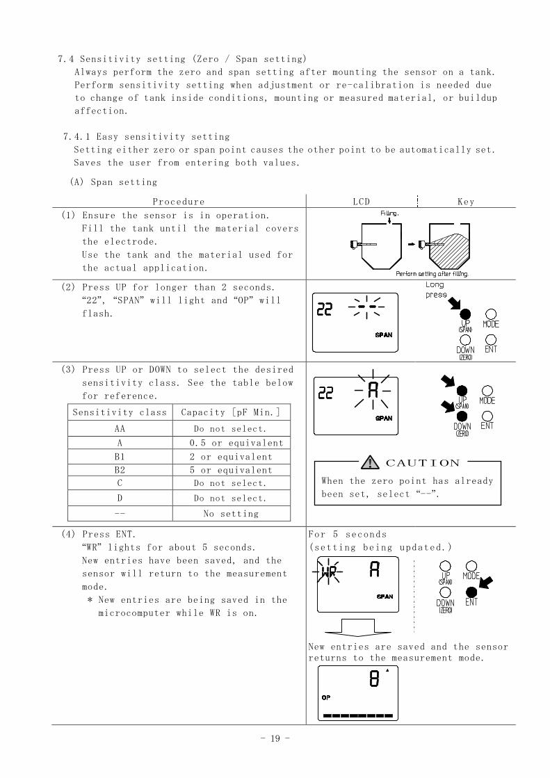
7.4 Sensitivity setting (Zero / Span setting)
Always perform the zero and span setting after mounting the sensor on a tank.
Perform sensitivity setting when adjustment or re-calibration is needed due
to change of tank inside conditions, mounting or measured material, or buildup
affection.
7.4.1 Easy sensitivity setting
Setting either zero or span point causes the other point to be automatically set.
Saves the user from entering both values.
(A) Span setting
Procedure LCD Key
(1) Ensure the sensor is in operation.
Fill the tank until the material covers
the electrode.
Use the tank and the material used for
the actual application.
(2) Press UP for longer than 2 seconds.
“22”, “SPAN” will light and “OP” will
flash.
(3) Press UP or DOWN to select the desired
sensitivity class. See the table below
for reference.
Sensitivity class Capacity [pF Min.]
AA Do not select.
A 0.5 or equivalent
B1 2 or equivalent
B2 5 or equivalent
C Do not select.
D Do not select.
-- No setting
(4) Press ENT.
“WR” lights for about 5 seconds.
New entries have been saved, and the
sensor will return to the measurement
mode.
* New entries are being saved in the
microcomputer while WR is on.
For 5 seconds
(setting being updated.)
New entries are saved and the sensorreturns to the measurement mode.
When the zero point has already
been set, select “--”.
CAUTION
- 20 -
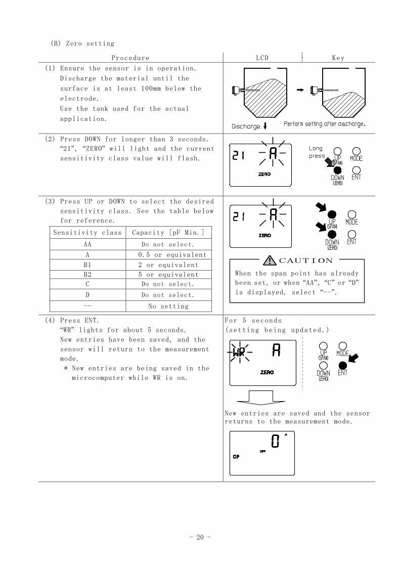
(B) Zero setting
Procedure LCD Key
(1) Ensure the sensor is in operation.
Discharge the material until the
surface is at least 100mm below the
electrode.
Use the tank used for the actual
application.
(2) Press DOWN for longer than 3 seconds.
“21”, “ZERO” will light and the current
sensitivity class value will flash.
(3) Press UP or DOWN to select the desired
sensitivity class. See the table below
for reference.
Sensitivity class Capacity [pF Min.]
AA Do not select.
A 0.5 or equivalent
B1 2 or equivalent
B2 5 or equivalent
C Do not select.
D Do not select.
-- No setting
(4) Press ENT.
“WR” lights for about 5 seconds.
New entries have been saved, and the
sensor will return to the measurement
mode.
* New entries are being saved in the
microcomputer while WR is on.
For 5 seconds
(setting being updated.)
New entries are saved and the sensorreturns to the measurement mode.
When the span point has already
been set, or when “AA”, “C” or “D”
is displayed, select “--”.
CAUTION
- 21 -
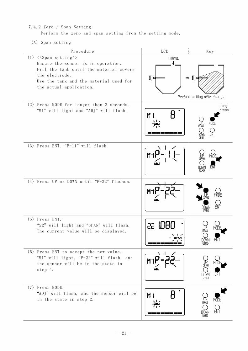
7.4.2 Zero / Span Setting
Perform the zero and span setting from the setting mode.
(A) Span setting
Procedure LCD Key
(1) <<Span setting>>
Ensure the sensor is in operation.
Fill the tank until the material covers
the electrode.
Use the tank and the material used for
the actual application.
(2) Press MODE for longer than 2 seconds.
“M1” will light and “ADJ” will flash.
(3) Press ENT. “P-11” will flash.
(4) Press UP or DOWN until “P-22” flashes.
(5) Press ENT.
“22” will light and “SPAN” will flash.
The current value will be displayed.
(6) Press ENT to accept the new value.
“M1” will light, “P-22” will flash, and
the sensor will be in the state in
step 4.
(7) Press MODE.
“ADJ” will flash, and the sensor will be
in the state in step 2.
- 22 -
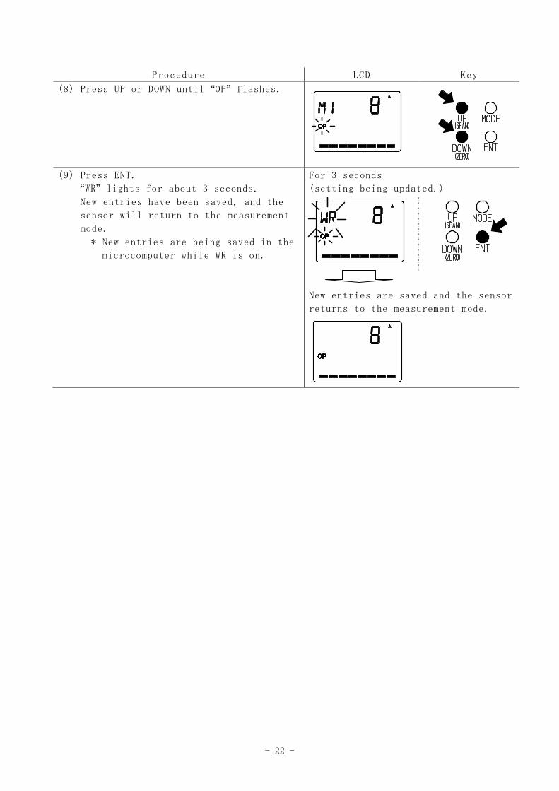
Procedure LCD Key
(8) Press UP or DOWN until “OP” flashes.
(9) Press ENT.
“WR” lights for about 3 seconds.
New entries have been saved, and the
sensor will return to the measurement
mode.
* New entries are being saved in the
microcomputer while WR is on.
For 3 seconds
(setting being updated.)
New entries are saved and the sensor
returns to the measurement mode.
- 23 -
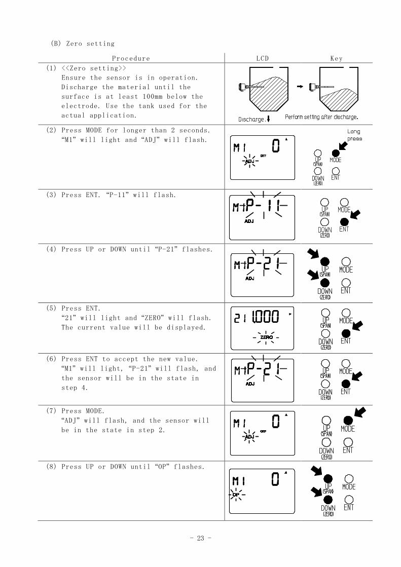
(B) Zero setting
Procedure LCD Key
(1) <<Zero setting>>
Ensure the sensor is in operation.
Discharge the material until the
surface is at least 100mm below the
electrode. Use the tank used for the
actual application.
(2) Press MODE for longer than 2 seconds.
“M1” will light and “ADJ” will flash.
(3) Press ENT. “P-11” will flash.
(4) Press UP or DOWN until “P-21” flashes.
(5) Press ENT.
“21” will light and “ZERO” will flash.
The current value will be displayed.
(6) Press ENT to accept the new value.
“M1” will light, “P-21” will flash, and
the sensor will be in the state in
step 4.
(7) Press MODE.
“ADJ” will flash, and the sensor will
be in the state in step 2.
(8) Press UP or DOWN until “OP” flashes.
- 24 -
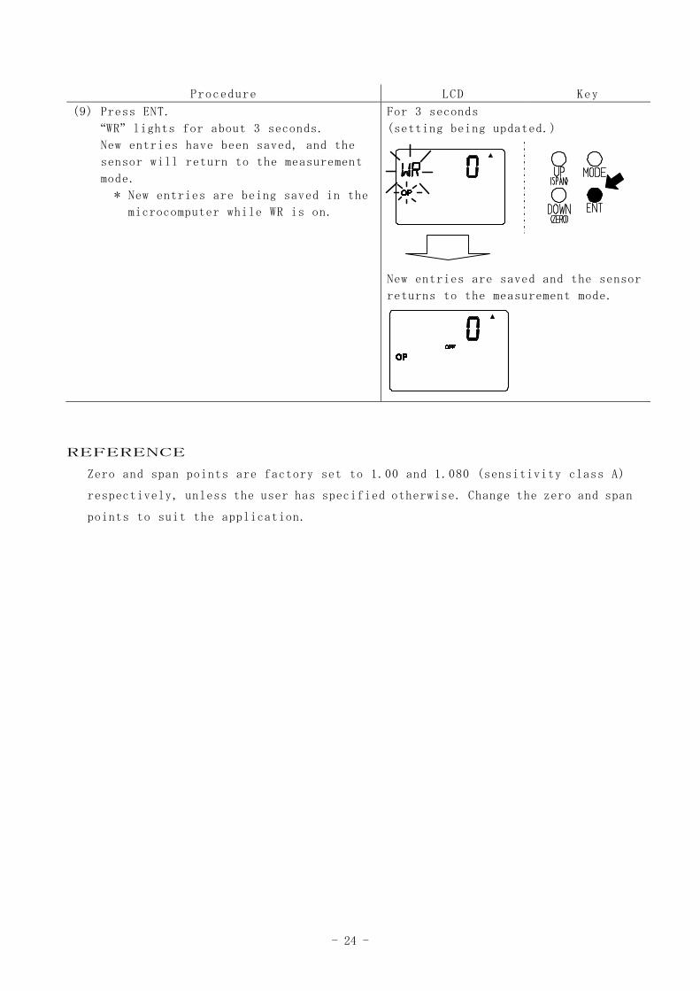
REFERENCE
Zero and span points are factory set to 1.00 and 1.080 (sensitivity class A)
respectively, unless the user has specified otherwise. Change the zero and span
points to suit the application.
Procedure LCD Key
(9) Press ENT.
“WR” lights for about 3 seconds.
New entries have been saved, and the
sensor will return to the measurement
mode.
* New entries are being saved in the
microcomputer while WR is on.
For 3 seconds
(setting being updated.)
New entries are saved and the sensor
returns to the measurement mode.
- 25 -
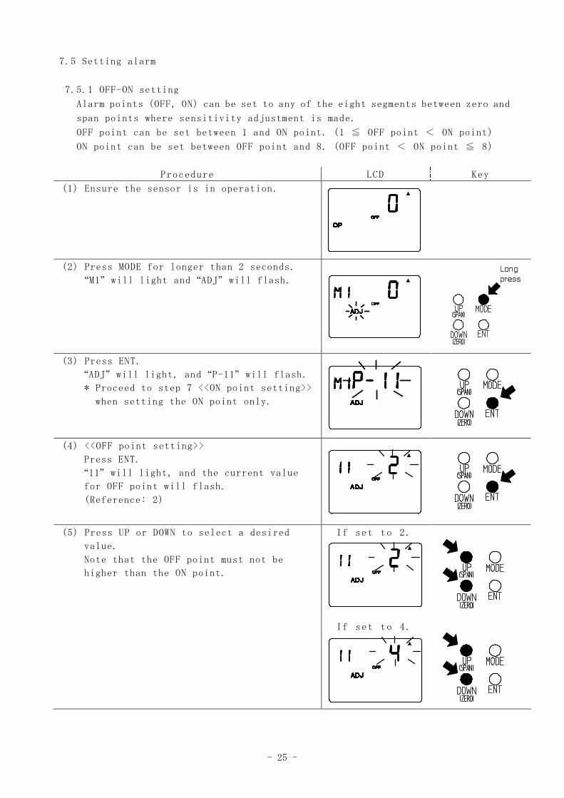
7.5 Setting alarm
7.5.1 OFF-ON setting
Alarm points (OFF, ON) can be set to any of the eight segments between zero and
span points where sensitivity adjustment is made.
OFF point can be set between 1 and ON point. (1 ≦ OFF point < ON point)
ON point can be set between OFF point and 8. (OFF point < ON point ≦ 8)
Procedure LCD Key
(1) Ensure the sensor is in operation.
(2) Press MODE for longer than 2 seconds.
“M1” will light and “ADJ” will flash.
(3) Press ENT.
“ADJ” will light, and “P-11” will flash.
* Proceed to step 7 <<ON point setting>>
when setting the ON point only.
(4) <<OFF point setting>>
Press ENT.
“11” will light, and the current value
for OFF point will flash.
(Reference: 2)
(5) Press UP or DOWN to select a desired
value.
Note that the OFF point must not be
higher than the ON point.
If set to 2.
If set to 4.
- 26 -
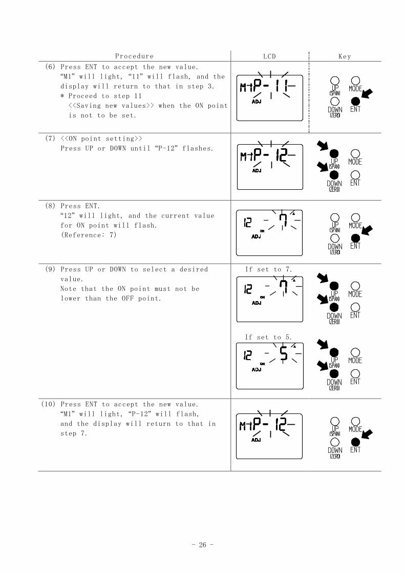
Procedure LCD Key
(6) Press ENT to accept the new value.
“M1” will light, “11” will flash, and the
display will return to that in step 3.
* Proceed to step 11
<<Saving new values>> when the ON point
is not to be set.
(7) <<ON point setting>>
Press UP or DOWN until “P-12” flashes.
(8) Press ENT.
“12” will light, and the current value
for ON point will flash.
(Reference: 7)
(9) Press UP or DOWN to select a desired
value.
Note that the ON point must not be
lower than the OFF point.
If set to 7.
If set to 5.
(10) Press ENT to accept the new value.
“M1” will light, “P-12” will flash,
and the display will return to that in
step 7.
- 27 -
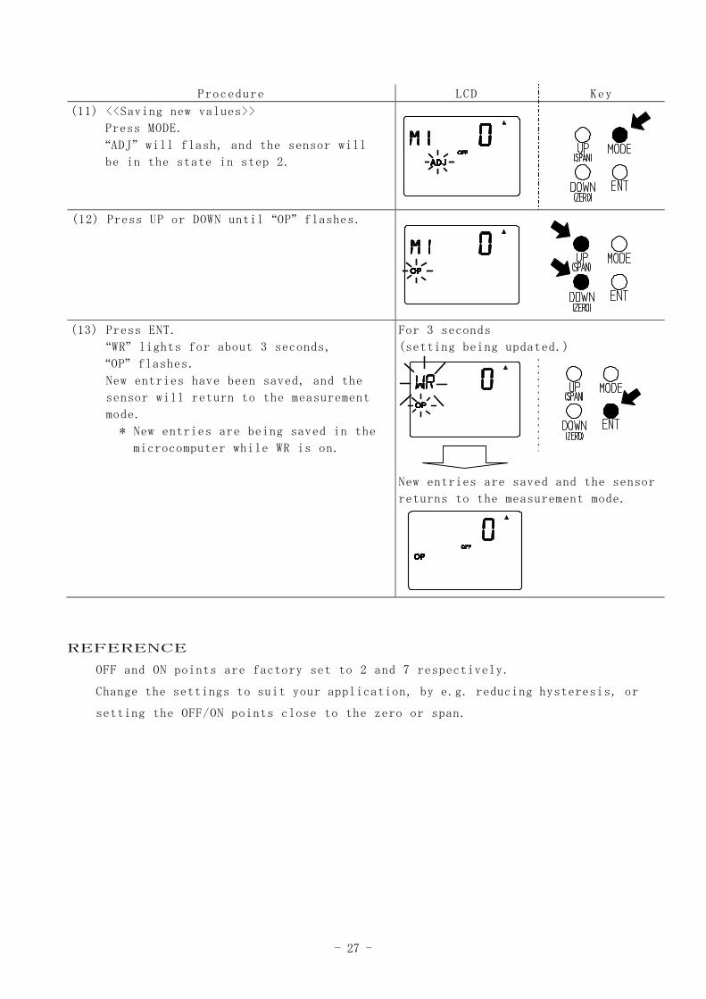
Procedure LCD Key
(11) <<Saving new values>>
Press MODE.
“ADJ” will flash, and the sensor will
be in the state in step 2.
(12) Press UP or DOWN until “OP” flashes.
(13) Press ENT.
“WR” lights for about 3 seconds,
“OP” flashes.
New entries have been saved, and the
sensor will return to the measurement
mode.
* New entries are being saved in the
microcomputer while WR is on.
For 3 seconds
(setting being updated.)
New entries are saved and the sensor
returns to the measurement mode.
REFERENCE
OFF and ON points are factory set to 2 and 7 respectively.
Change the settings to suit your application, by e.g. reducing hysteresis, or
setting the OFF/ON points close to the zero or span.
- 28 -
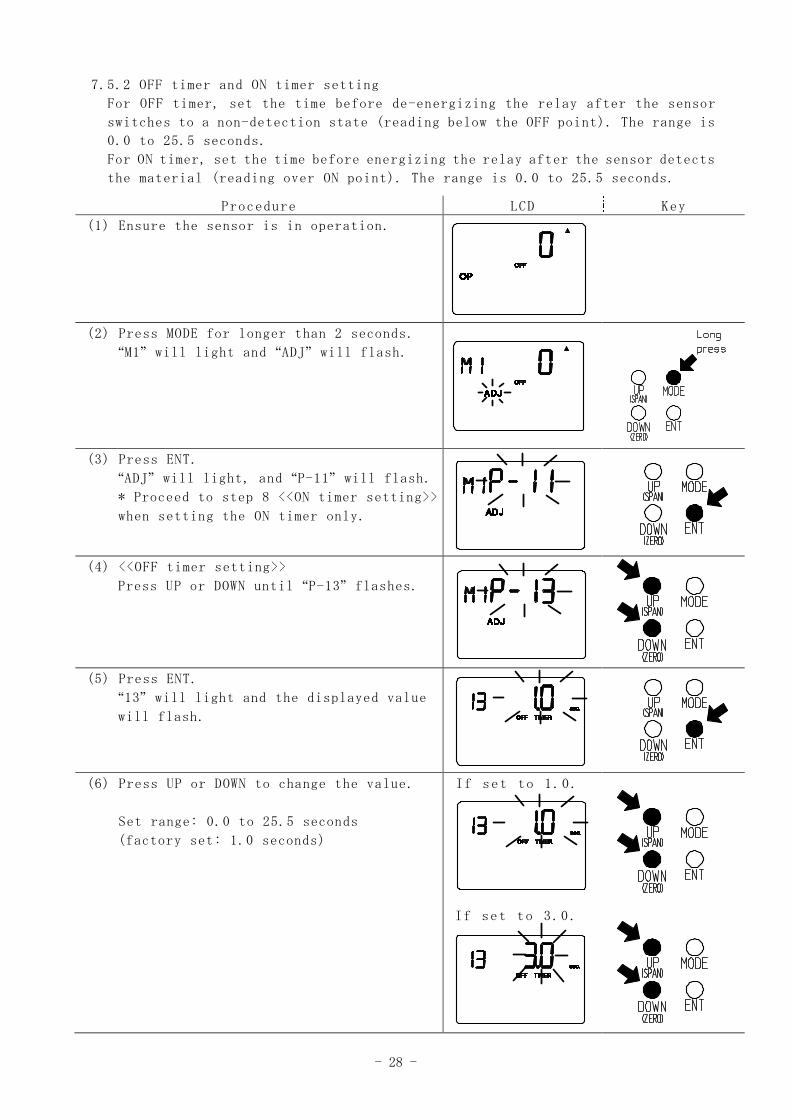
7.5.2 OFF timer and ON timer setting
For OFF timer, set the time before de-energizing the relay after the sensor
switches to a non-detection state (reading below the OFF point). The range is
0.0 to 25.5 seconds.
For ON timer, set the time before energizing the relay after the sensor detects
the material (reading over ON point). The range is 0.0 to 25.5 seconds.
Procedure LCD Key
(1) Ensure the sensor is in operation.
(2) Press MODE for longer than 2 seconds.
“M1” will light and “ADJ” will flash.
(3) Press ENT.
“ADJ” will light, and “P-11” will flash.
* Proceed to step 8 <<ON timer setting>>
when setting the ON timer only.
(4) <<OFF timer setting>>
Press UP or DOWN until “P-13” flashes.
(5) Press ENT.
“13” will light and the displayed value
will flash.
(6) Press UP or DOWN to change the value.
Set range: 0.0 to 25.5 seconds
(factory set: 1.0 seconds)
If set to 1.0.
If set to 3.0.
- 29 -
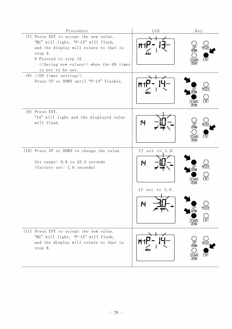
Procedure LCD Key
(7) Press ENT to accept the new value.
“M1” will light, “P-13” will flash,
and the display will return to that in
step 4.
* Proceed to step 12
<<Saving new values>> when the ON timer
is not to be set.
(8) <<ON timer setting>>
Press UP or DOWN until “P-14” flashes.
(9) Press ENT.
“14” will light and the displayed value
will flash.
(10) Press UP or DOWN to change the value.
Set range: 0.0 to 25.5 seconds
(factory set: 1.0 seconds)
If set to 1.0.
If set to 3.0.
(11) Press ENT to accept the new value.
“M1” will light, “P-14” will flash,
and the display will return to that in
step 8.
- 30 -
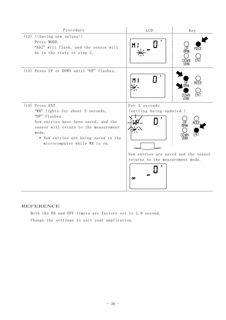
Procedure LCD Key
(12) <<Saving new values>>
Press MODE.
“ADJ” will flash, and the sensor will
be in the state in step 2.
(13) Press UP or DOWN until “OP” flashes.
(14) Press ENT.
“WR” lights for about 3 seconds,
“OP” flashes.
New entries have been saved, and the
sensor will return to the measurement
mode.
* New entries are being saved in the
microcomputer while WR is on.
For 3 seconds
(setting being updated.)
New entries are saved and the sensor
returns to the measurement mode.
REFERENCE
Both the ON and OFF timers are factory set to 1.0 second.
Change the settings to suit your application.
- 31 -
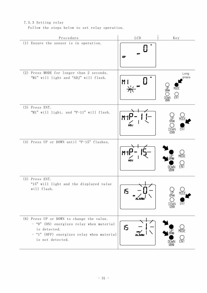
7.5.3 Setting relay
Follow the steps below to set relay operation.
Procedure LCD Key
(1) Ensure the sensor is in operation.
(2) Press MODE for longer than 2 seconds.
“M1” will light and “ADJ” will flash.
(3) Press ENT.
“M1” will light, and “P-11” will flash.
(4) Press UP or DOWN until “P-15” flashes.
(5) Press ENT.
“15” will light and the displayed value
will flash.
(6) Press UP or DOWN to change the value.
- “0” (ON) energizes relay when material
is detected.
- “1” (OFF) energizes relay when material
is not detected.
- 32 -
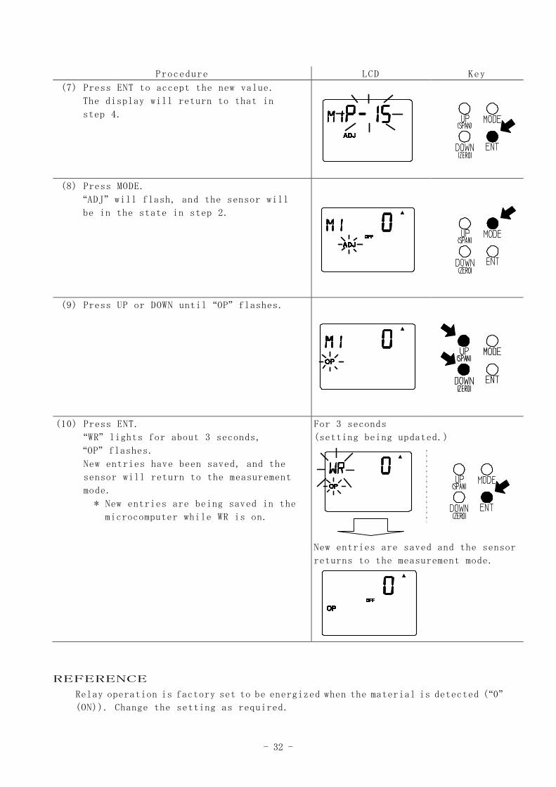
Procedure LCD Key
(7) Press ENT to accept the new value.
The display will return to that in
step 4.
(8) Press MODE.
“ADJ” will flash, and the sensor will
be in the state in step 2.
(9) Press UP or DOWN until “OP” flashes.
(10) Press ENT.
“WR” lights for about 3 seconds,
“OP” flashes.
New entries have been saved, and the
sensor will return to the measurement
mode.
* New entries are being saved in the
microcomputer while WR is on.
For 3 seconds
(setting being updated.)
New entries are saved and the sensor
returns to the measurement mode.
REFERENCE
Relay operation is factory set to be energized when the material is detected (“0”
(ON)). Change the setting as required.
- 33 -
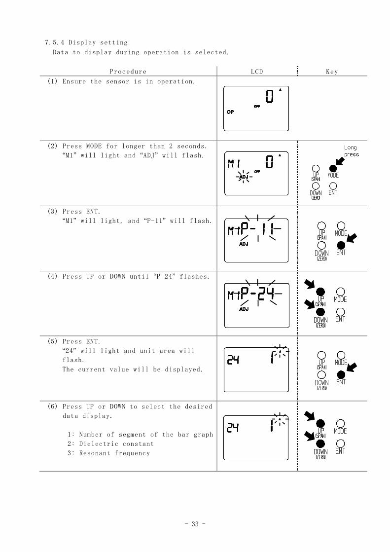
7.5.4 Display setting
Data to display during operation is selected.
Procedure LCD Key
(1) Ensure the sensor is in operation.
(2) Press MODE for longer than 2 seconds.
“M1” will light and “ADJ” will flash.
(3) Press ENT.
“M1” will light, and “P-11” will flash.
(4) Press UP or DOWN until “P-24” flashes.
(5) Press ENT.
“24” will light and unit area will
flash.
The current value will be displayed.
(6) Press UP or DOWN to select the desired
data display.
1: Number of segment of the bar graph
2: Dielectric constant
3: Resonant frequency
- 34 -
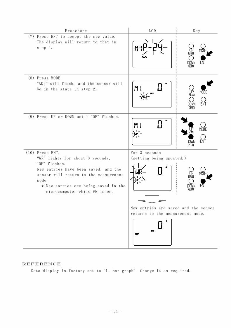
Procedure LCD Key
(7) Press ENT to accept the new value.
The display will return to that in
step 4.
(8) Press MODE.
“ADJ” will flash, and the sensor will
be in the state in step 2.
(9) Press UP or DOWN until “OP” flashes.
(10) Press ENT.
“WR” lights for about 3 seconds,
“OP” flashes.
New entries have been saved, and the
sensor will return to the measurement
mode.
* New entries are being saved in the
microcomputer while WR is on.
For 3 seconds
(setting being updated.)
New entries are saved and the sensor
returns to the measurement mode.
REFERENCE
Data display is factory set to “1: bar graph”. Change it as required.
- 35 -
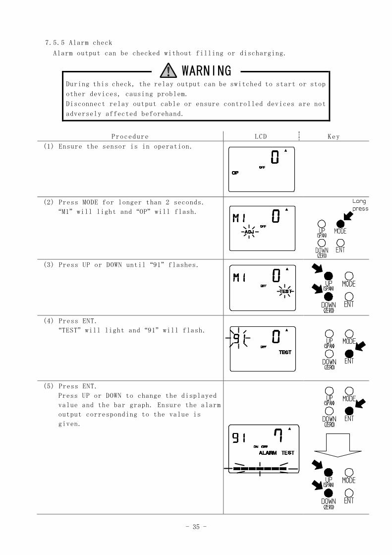
7.5.5 Alarm check
Alarm output can be checked without filling or discharging.
WARNINGDuring this check, the relay output can be switched to start or stop
other devices, causing problem.
Disconnect relay output cable or ensure controlled devices are not
adversely affected beforehand.
Procedure LCD Key
(1) Ensure the sensor is in operation.
(2) Press MODE for longer than 2 seconds.
“M1” will light and “OP” will flash.
(3) Press UP or DOWN until “91” flashes.
(4) Press ENT.
“TEST” will light and “91” will flash.
(5) Press ENT.
Press UP or DOWN to change the displayed
value and the bar graph. Ensure the alarm
output corresponding to the value is
given.
- 36 -
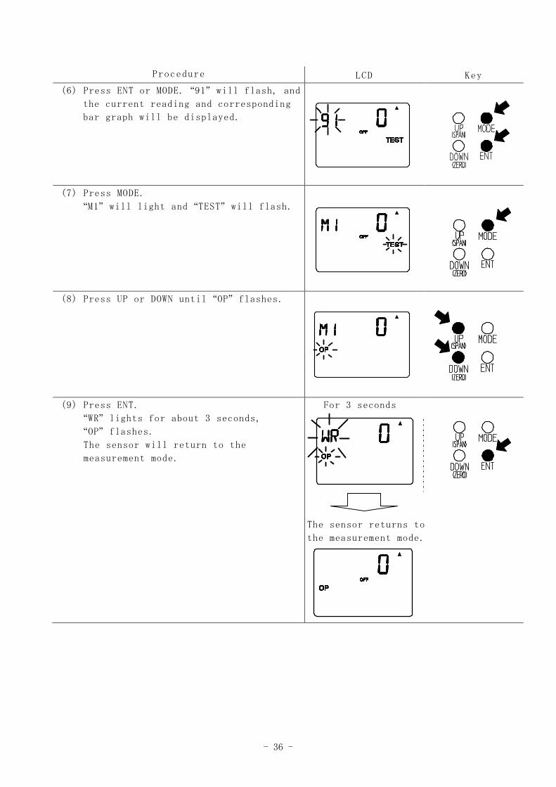
Procedure LCD Key
(6) Press ENT or MODE. “91” will flash, and
the current reading and corresponding
bar graph will be displayed.
(7) Press MODE.
“M1” will light and “TEST” will flash.
(8) Press UP or DOWN until “OP” flashes.
(9) Press ENT.
“WR” lights for about 3 seconds,
“OP” flashes.
The sensor will return to the
measurement mode.
For 3 seconds
The sensor returns to
the measurement mode.
- 37 -
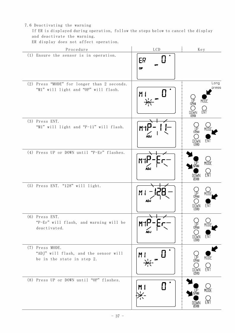
7.6 Deactivating the warning
If ER is displayed during operation, follow the steps below to cancel the display
and deactivate the warning.
ER display does not affect operation.
Procedure LCD Key
(1) Ensure the sensor is in operation.
(2) Press “MODE” for longer than 2 seconds.
“M1” will light and “OP” will flash.
(3) Press ENT.
“M1” will light and “P-11” will flash.
(4) Press UP or DOWN until “P-Er” flashes.
(5) Press ENT. “128” will light.
(6) Press ENT.
“P-Er” will flash, and warning will be
deactivated.
(7) Press MODE.
“ADJ” will flash, and the sensor will
be in the state in step 2.
(8) Press UP or DOWN until “OP” flashes.
- 38 -
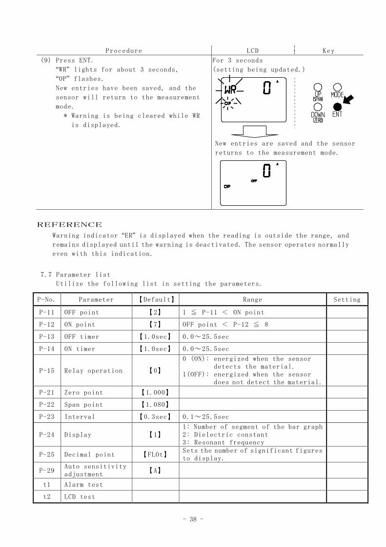
Procedure LCD Key
(9) Press ENT.
“WR” lights for about 3 seconds,
“OP” flashes.
New entries have been saved, and the
sensor will return to the measurement
mode.
* Warning is being cleared while WR
is displayed.
For 3 seconds
(setting being updated.)
New entries are saved and the sensor
returns to the measurement mode.
REFERENCE
Warning indicator “ER” is displayed when the reading is outside the range, and
remains displayed until the warning is deactivated. The sensor operates normally
even with this indication.
7.7 Parameter list
Utilize the following list in setting the parameters.
P-No. Parameter 【Default】 Range Setting
P-11 OFF point 【2】 1 ≦ P-11 < ON point
P-12 ON point 【7】 OFF point < P-12 ≦ 8
P-13 OFF timer 【1.0sec】 0.0~25.5sec
P-14 ON timer 【1.0sec】 0.0~25.5sec
P-15 Relay operation 【0】
0 (ON): energized when the sensordetects the material.
1(OFF): energized when the sensordoes not detect the material.
P-21 Zero point 【1.000】
P-22 Span point 【1.080】
P-23 Interval 【0.3sec】 0.1~25.5sec
P-24 Display 【1】1: Number of segment of the bar graph2: Dielectric constant3: Resonant frequency
P-25 Decimal point 【FLOt】Sets the number of significant figuresto display.
P-29Auto sensitivityadjustment
【A】
t1 Alarm test
t2 LCD test
- 39 -
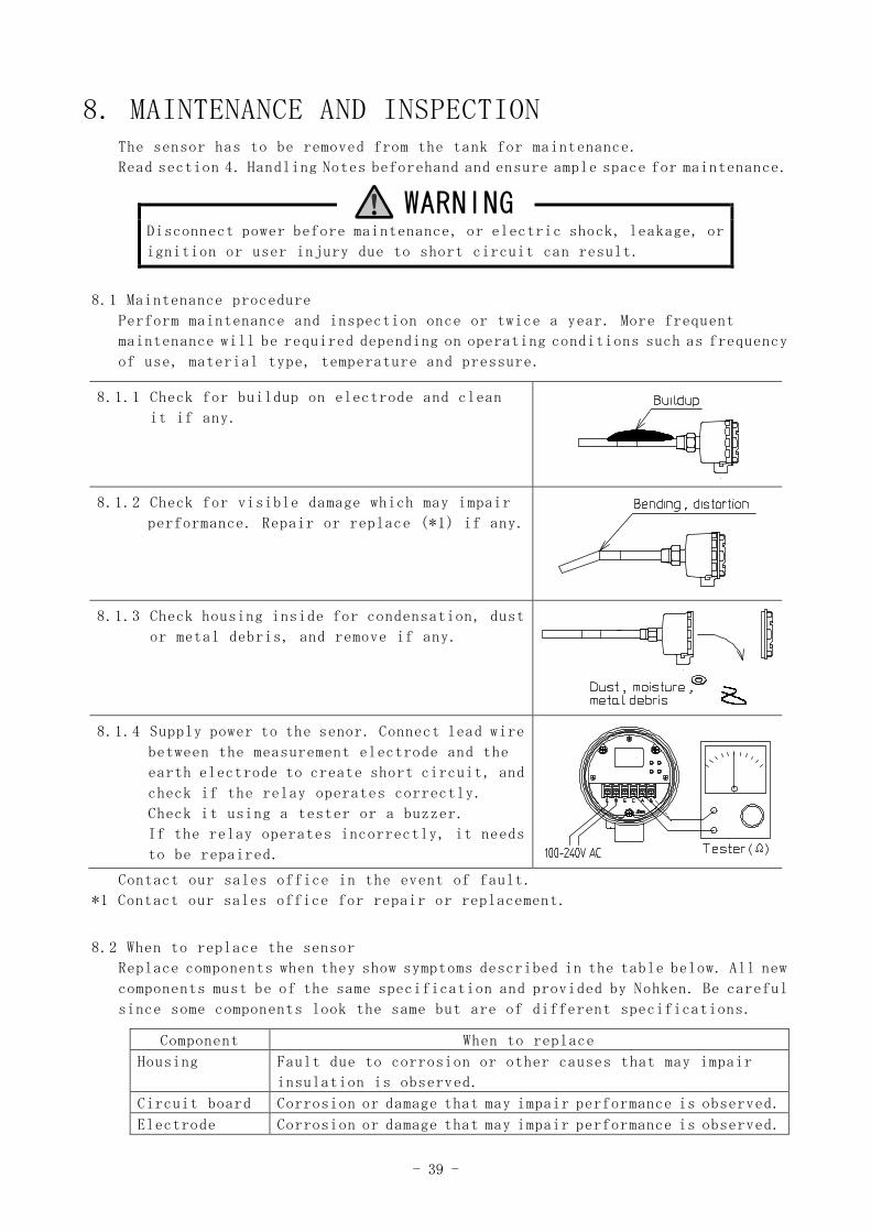
8. MAINTENANCE AND INSPECTIONThe sensor has to be removed from the tank for maintenance.
Read section 4. Handling Notes beforehand and ensure ample space for maintenance.
WARNINGDisconnect power before maintenance, or electric shock, leakage, or
ignition or user injury due to short circuit can result.
8.1 Maintenance procedure
Perform maintenance and inspection once or twice a year. More frequent
maintenance will be required depending on operating conditions such as frequency
of use, material type, temperature and pressure.
8.1.1 Check for buildup on electrode and clean
it if any.
8.1.2 Check for visible damage which may impair
performance. Repair or replace (*1) if any.
8.1.3 Check housing inside for condensation, dust
or metal debris, and remove if any.
8.1.4 Supply power to the senor. Connect lead wire
between the measurement electrode and the
earth electrode to create short circuit, and
check if the relay operates correctly.
Check it using a tester or a buzzer.
If the relay operates incorrectly, it needs
to be repaired.
Contact our sales office in the event of fault.
*1 Contact our sales office for repair or replacement.
8.2 When to replace the sensor
Replace components when they show symptoms described in the table below. All new
components must be of the same specification and provided by Nohken. Be careful
since some components look the same but are of different specifications.
Component When to replace
Housing Fault due to corrosion or other causes that may impair
insulation is observed.
Circuit board Corrosion or damage that may impair performance is observed.
Electrode Corrosion or damage that may impair performance is observed.
- 40 -
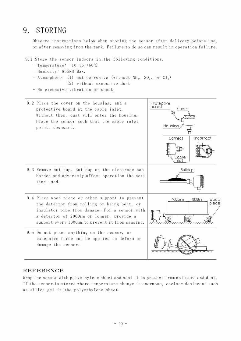
9. STORINGObserve instructions below when storing the sensor after delivery before use,
or after removing from the tank. Failure to do so can result in operation failure.
9.1 Store the sensor indoors in the following conditions.
- Temperature: -10 to +60℃
- Humidity: 85%RH Max.
- Atmosphere: (1) not corrosive (without NH3, SO2, or Cl2)
(2) without excessive dust
- No excessive vibration or shock
9.2 Place the cover on the housing, and a
protective board at the cable inlet.
Without them, dust will enter the housing.
Place the sensor such that the cable inlet
points downward.
9.3 Remove buildup. Buildup on the electrode can
harden and adversely affect operation the next
time used.
9.4 Place wood piece or other support to prevent
the detector from rolling or being bent, or
insulator pipe from damage. For a sensor with
a detector of 2000mm or longer, provide a
support every 1000mm to prevent it from sagging.
9.5 Do not place anything on the sensor, or
excessive force can be applied to deform or
damage the sensor.
REFERENCE
Wrap the sensor with polyethylene sheet and seal it to protect from moisture and dust.
If the sensor is stored where temperature change is enormous, enclose desiccant such
as silica gel in the polyethylene sheet.
- 41 -
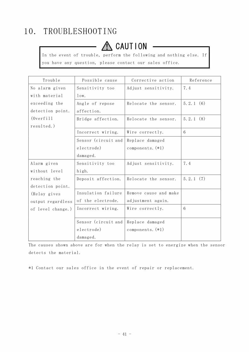
10. TROUBLESHOOTING
CAUTIONIn the event of trouble, perform the following and nothing else. If
you have any question, please contact our sales office.
Trouble Possible cause Corrective action Reference
No alarm given
with material
exceeding the
detection point.
(Overfill
resulted.)
Sensitivity too
low.
Adjust sensitivity. 7.4
Angle of repose
affection.
Relocate the sensor. 5.2.1 (6)
Bridge affection. Relocate the sensor. 5.2.1 (8)
Incorrect wiring. Wire correctly. 6
Sensor (circuit and
electrode)
damaged.
Replace damaged
components.(*1)
Alarm given
without level
reaching the
detection point.
(Relay gives
output regardless
of level change.)
Sensitivity too
high.
Adjust sensitivity. 7.4
Deposit affection. Relocate the sensor. 5.2.1 (7)
Insulation failure
of the electrode.
Remove cause and make
adjustment again.
Incorrect wiring. Wire correctly. 6
Sensor (circuit and
electrode)
damaged.
Replace damaged
components.(*1)
The causes shown above are for when the relay is set to energize when the sensor
detects the material.
*1 Contact our sales office in the event of repair or replacement.
- 42 -
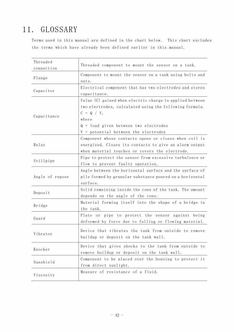
11. GLOSSARYTerms used in this manual are defined in the chart below. This chart excludes
the terms which have already been defined earlier in this manual.
Threaded
connectionThreaded component to mount the sensor on a tank.
FlangeComponent to mount the sensor on a tank using bolts and
nuts.
CapacitorElectrical component that has two electrodes and stores
capacitance.
Capacitance
Value (C) gained when electric charge is applied between
two electrodes, calculated using the following formula.
C = Q / V,
where
Q = load given between two electrodes
V = potential between the electrodes
Relay
Component whose contacts opens or closes when coil is
energized. Closes its contacts to give an alarm output
when material touches or covers the electrode.
StillpipePipe to protect the sensor from excessive turbulence or
flow to prevent faulty operation.
Angle of repose
Angle between the horizontal surface and the surface of
pile formed by granular substance poured on a horizontal
surface.
DepositSolid remaining inside the cone of the tank. The amount
depends on the angle of the cone.
BridgeMaterial forming itself into the shape of a bridge in
the tank.
GuardPlate or pipe to protect the sensor against being
deformed by force due to falling or flowing material.
VibratorDevice that vibrates the tank from outside to remove
buildup or deposit on the tank wall.
KnockerDevice that gives shocks to the tank from outside to
remove buildup or deposit on the tank wall.
SunshieldComponent to be placed over the housing to protect it
from direct sunlight.
ViscosityMeasure of resistance of a fluid.

HEAD OFFICE : 15-29,Hiroshiba-cho,Suita-city,Osaka 564-0052,Japan.
TEL:06-6386-8141 FAX:06-6386-8140
TOKYO BRANCH OFFICE : 67,Kandasakumagashi,Chiyoda-ku,Tokyo 101-0026,Japan.
TEL:03-5835-3311 FAX:03-5835-3316
NAGOYA OFFICE : 3-10-17,Uchiyama,Chikusa-ku,Nagoya-city,Aichi 464-0075,Japan.
TEL:052-731-5751 FAX:052-731-5780
KYUSHU OFFICE : 14-1,2-chome,Asano,Kokurakita-ku,Kitakyushu-city,Fukuoka 802-0001,Japan.
TEL:093-521-9830 FAX:093-521-9834