Embed Size (px)
Citation preview
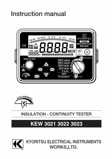
Instruction manual
INSULATION - CONTINUITY TESTER
KEW 3021 3022 3023
KYORITSU ELECTRICAL INSTRUMENTSWORKS,LTD.
Contents
1.Safety warnings ……………………………………………………12.Features ……………………………………………………………33.Specification ………………………………………………………44.Instrument layout …………………………………………………85.Preparation for measurement ……………………………………95-1 Test lead connection ………………………………………95-2 Checks on Test lead and Fuse ……………………………96.Measurement ……………………………………………………106-1 Voltage measurement(Mains disconnection check) ……106-2 Insulation resistance measurement ………………………106-3 Continuous measurement …………………………………136-4 Output voltage characteristics ……………………………136-5 Measurement of resistance (Continuity check) …………146-6 Backlight function …………………………………………156-7 Auto-power-off ………………………………………………157. Functions keys ……………………………………………………167-1 Comparator function ………………………………………167-2 Memory (save) function ……………………………………178.Fuse & Battery replacement ……………………………………188-1 Battery replacement ………………………………………188-2 Fuse replacement …………………………………………189.Notes on Housing case and accessories ………………………199-1 Case lid………………………………………………………199-2 Neck strap and Cord case ………………………………199-3 Test prods and replacement ……………………………209-4 Adaptors for the Earth cord and replacement……………2010.Cleaning of the instrument ……………………………………2111.Servicing …………………………………………………………21
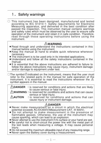
1.Safety warnings
○ This instrument has been designed, manufactured and testedaccording to IEC 61010-1: Safety requirements for ElectronicMeasuring apparatus, and delivered in the best condition afterpassed the inspection. This instruction manual contains warningsand safety rules which must be observed by the user to ensure safeoperation of the instrument and retain it in safe condition. Therefore,read through these operating instructions before using theinstrument.
WARNING¡Read through and understand the instructions contained in thismanual before using the instrument.
¡Keep the manual at hand to enable quick reference whenevernecessary.
¡The instrument is to be used only in its intended applications.¡Understand and follow all the safety instructions contained in themanual.
¡It is essential that the above instructions are adhered to failure tofollow the above instructions may cause injury, instrument damageand/or damage to equipment under test.
○The symbol indicated on the instrument, means that the user mustrefer to the related parts in the manual for safe operation of theinstrument. It is essential to read the instructions wherever the symbol appears in the manual.
DANGER :is reserved for conditions and actions that are likelyto cause serious or fatal injury.
WARNING:is reserved for conditions and actions that can causeserious or fatal injury.
AUTION :is reserved for conditions and actions that cancause injury or instrument damage.
DANGER¡Never make measurement on a circuit in which the electricalpotential exceeds AC/DC600V(Measurement CAT. III 600V).
¡Do not attempt to make measurement in the presence offlammable gasses. Otherwise, the use of the instrument maycause sparking, which can lead to an explosion.
¡Never attempt to use the instrument if it's surface or your hand are wet.¡Be careful not to short-circuit the power line with the metal part ofthe test leads when measuring a voltage. It may cause personalinjury.
¡Do not exceed the maximum allowable input of any measuring range.¡Never open the Battery cover during a measurement.
― 1 ―
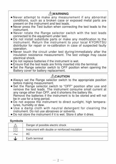
WARNING¡Never attempt to make any measurement if any abnormalconditions, such as a broken case or exposed metal parts arepresent on the instrument and test leads.
¡Never press the Test button when connecting the test leads to theinstrument.
¡Never rotate the Range selector switch with the test leadsconnected to the equipment under test.
¡Do not install substitute parts or make any modification to theinstrument. Return the instrument to your local KYORITSUdistributor for repair or re-calibration in case of suspected faultyoperation.
¡Never touch the circuit under test during/immediately after theinsulation resistance measurement. The test voltage may causeelectrical shock.
¡Do not replace batteries if the instrument is wet.¡Ensure that the test leads are firmly inserted into the terminal.¡Set the Range selector switch to OFF position when opening theBattery cover for battery replacement.
CAUTION¡Always set the Range selector switch to the appropriate positionbefore making measurement.
¡Set the Range selector switch to "OFF" position after use andremove the test leads. The instrument consume small current atany range other than OFF, and it shortens the battery life. Remove the batteries if the instrument is to be stored and will notbe in use for a long period.
¡Do not expose the instrument to direct sunlight, high tempera-tures, humidity or dew.
¡Use a damp cloth with neutral detergent for cleaning theinstrument. Do not use abrasives or solvents.
¡Do not store the instrument if it is wet. Store it after it dries.
Symbols
― 2 ―
F~
Danger of possible electric shock
Instrument with double or reinforced insulation
AC
Earth terminal
― 3 ―
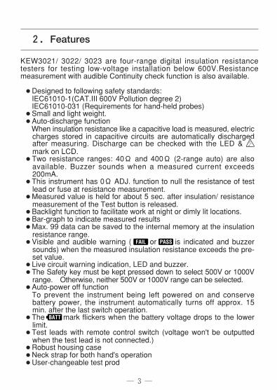
2.Features
KEW3021/ 3022/ 3023 are four-range digital insulation resistancetesters for testing low-voltage installation below 600V.Resistancemeasurement with audible Continuity check function is also available.
¡Designed to following safety standards:IEC61010-1(CAT.III 600V Pollution degree 2)IEC61010-031 (Requirements for hand-held probes)
¡Small and light weight.¡Auto-discharge functionWhen insulation resistance like a capacitive load is measured, electriccharges stored in capacitive circuits are automatically dischargedafter measuring. Discharge can be checked with the LED & mark on LCD.
¡Two resistance ranges: 40Ω and 400Ω (2-range auto) are alsoavailable. Buzzer sounds when a measured current exceeds200mA.
¡This instrument has 0Ω ADJ. function to null the resistance of testlead or fuse at resistance measurement.
¡Measured value is held for about 5 sec. after insulation/ resistancemeasurement of the Test button is released.
¡Backlight function to facilitate work at night or dimly lit locations.¡Bar-graph to indicate measured results¡Max. 99 data can be saved to the internal memory at the insulationresistance range.
¡Visible and audible warning ( or is indicated and buzzersounds) when the measured insulation resistance exceeds the pre-set value.
¡Live circuit warning indication, LED and buzzer.¡The Safety key must be kept pressed down to select 500V or 1000Vrange. Otherwise, neither 500V or 1000V range can be selected.
¡Auto-power off functionTo prevent the instrument being left powered on and conservebattery power, the instrument automatically turns off approx. 15min. after the last switch operation.
¡The mark flickers when the battery voltage drops to the lowerlimit.
¡Test leads with remote control switch (voltage won't be outputtedwhen the test lead is not connected.)
¡Robust housing case¡Neck strap for both hand's operation¡User-changeable test prod
― 4―
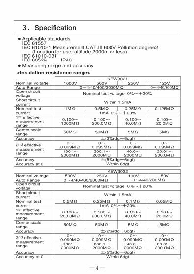
¡Applicable standardsIEC 61557IEC 61010-1 Measurement CAT.III 600V Pollution degree2(Location for use: altitude 2000m or less)
IEC 61010-031IEC 60529 IP40
¡Measuring range and accuracy
<Insulation resistance range>
3.Specification
Nominal voltageAuto RangeOpen circuitvoltageShort circuit currentNominal testcurrent1st effectivemeasurement rangeCenter scale rangeAccuracy
2nd effectivemeasurement range
AccuracyAccuracy at 0
KEW30211000V
0~4/40/400/2000MΩ
Nominal test voltage 0%~+20%
Within 1.5mA
1MΩ1mA 0%~+20%
0.100~1000MΩ
50MΩ
0~0.099MΩ1001~2000MΩ
200.1~2000MΩ
40.0~2000MΩ
20.01~200.0MΩ
0~0.099MΩ
0~0.099MΩ
0~0.099MΩ
±(2%rdg+6dgt)
±(5%rdg+6dgt)Within 6dgt
50MΩ 5MΩ 5MΩ
0.100~200.0MΩ
0.100~40.0MΩ
0.100~20.0MΩ
0.5MΩ 0.25MΩ 0.125MΩ
500V 250V 125V0~4/40/200MΩ
Nominal voltageAuto RangeOpen circuitvoltageShort circuit currentNominal testcurrent1st effectivemeasurement rangeCenter scale rangeAccuracy
2nd effectivemeasurement range
AccuracyAccuracy at 0
KEW3022500V
Nominal test voltage 0%~+20%
Within 1.5mA
0.5MΩ1mA 0%~+20%
0.100~200.0MΩ
50MΩ
0~0.099MΩ1001~2000MΩ
200.1~2000MΩ
40.0~2000MΩ
20.01~200.0MΩ
0~0.099MΩ
0~0.099MΩ
0~0.099MΩ
±(2%rdg+6dgt)
±(5%rdg+6dgt)Within 6dgt
50MΩ 5MΩ 5MΩ
0.100~200.0MΩ
0.100~40.0MΩ
0.100~20.0MΩ
0.25MΩ 0.1MΩ 0.05MΩ
50V0~4/40/400/2000MΩ
250V 100V0~4/40/200MΩ
― 5―
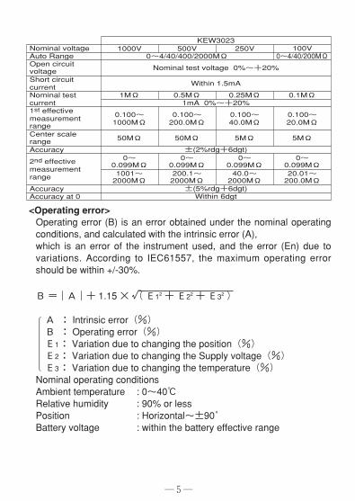
Nominal voltageAuto RangeOpen circuitvoltageShort circuit currentNominal testcurrent1st effectivemeasurement rangeCenter scale rangeAccuracy
2nd effectivemeasurement range
AccuracyAccuracy at 0
KEW30231000V
0~4/40/400/2000MΩ
Nominal test voltage 0%~+20%
Within 1.5mA
1MΩ1mA 0%~+20%
0.100~1000MΩ
50MΩ
0~0.099MΩ1001~2000MΩ
200.1~2000MΩ
40.0~2000MΩ
20.01~200.0MΩ
0~0.099MΩ
0~0.099MΩ
0~0.099MΩ
±(2%rdg+6dgt)
±(5%rdg+6dgt)Within 6dgt
50MΩ 5MΩ 5MΩ
0.100~200.0MΩ
0.100~40.0MΩ
0.100~20.0MΩ
0.5MΩ 0.25MΩ 0.1MΩ
500V 250V 100V0~4/40/200MΩ
<Operating error>Operating error (B) is an error obtained under the nominal operatingconditions, and calculated with the intrinsic error (A), which is an error of the instrument used, and the error (En) due tovariations. According to IEC61557, the maximum operating errorshould be within +/-30%.
B =―A―+ 1.15 × √(E12 + E22 + E32 )
A : Intrinsic error(%)B : Operating error(%)E1: Variation due to changing the position(%)E2: Variation due to changing the Supply voltage(%)E3: Variation due to changing the temperature(%)Nominal operating conditionsAmbient temperature : 0~40℃Relative humidity : 90% or lessPosition : Horizontal~±90゜Battery voltage : within the battery effective range
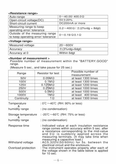
<Number of measurement >Possible number of measurement within the "BATTERY.GOOD"range.(Measure 5 sec., and take pause for 25 sec.)
Temperature : 0℃~40℃ (RH: 90% or less)&
humidity range : (no condensation)
Storage temperature : -20℃~60℃ (RH: 75% or less)&
humidity range : (no condensation)
Response time : Indicated value at each insulation resistancerange comes within accuracy within 5 sec. aftera resistance corresponding to the mid-valueand 0Ω is suddenly applied across themeasuring terminals. (It may take time whenmeasuring a capacitive load.)
Withstand voltage : AC5,320V(50/60Hz) for 5s. between theelectrical circuit and the enclosure.
Overload protection : The instrument operates properly after each ofthe voltage shown in the table below is appliedfor 10 sec.
20~600V±(3%rdg+6dgt)Within 6dgt
Measured voltageAccuracyAccuracy at 0
Auto-rangeOpen-circuit voltage(DC)Short-circuit currentMeasuring range to keepoperating error/ toleranceOutside of the measuring rangeto keep operating error/ tolerance
0~40.00/ 400.0Ω5V±20%DC200mA or more
0.2~400Ω/ ±(2%rdg + 8dgt)
0~0.19/Ω0.1Ω
― 6―
<Resistance range>
<Voltage range>
Range
50V100V125V250V500V1000VContinuity
Resistor for test
0.05MΩ0.1MΩ
0.125MΩ0.25MΩ0.5MΩ1MΩ1Ω
Possible number ofmeasurementat least 1300 timesat least 1300 timesat least 1200 timesat least 1000 timesat least 1000 timesat least 400 timesat least 1300 times
― 7―
Pickle type prod
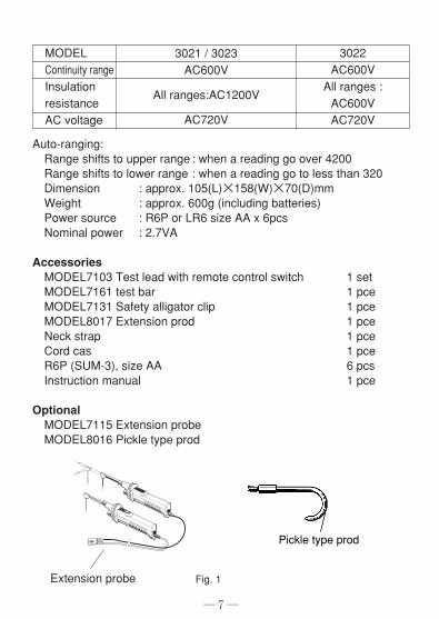
MODELContinuity rangeInsulationresistanceAC voltage
3021 / 3023AC600V
All ranges:AC1200V
AC720V
3022AC600VAll ranges :AC600VAC720V
Auto-ranging:Range shifts to upper range : when a reading go over 4200Range shifts to lower range : when a reading go to less than 320Dimension : approx. 105(L)×158(W)×70(D)mmWeight : approx. 600g (including batteries)Power source : R6P or LR6 size AA x 6pcsNominal power : 2.7VA
AccessoriesMODEL7103 Test lead with remote control switch 1 setMODEL7161 test bar 1 pceMODEL7131 Safety alligator clip 1 pceMODEL8017 Extension prod 1 pceNeck strap 1 pceCord cas 1 pceR6P (SUM-3), size AA 6 pcsInstruction manual 1 pce
OptionalMODEL7115 Extension probeMODEL8016 Pickle type prod
Extension probe Fig. 1
― 8―
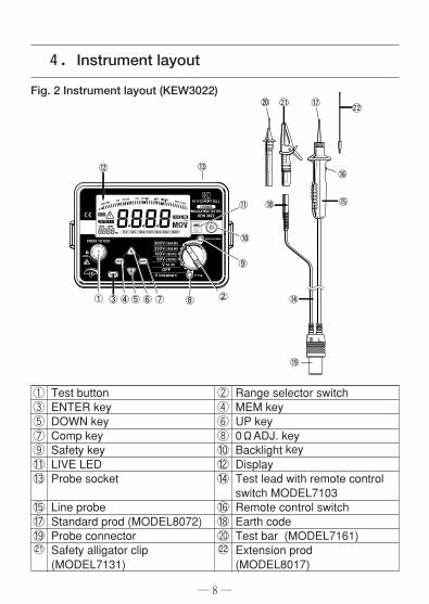
4.Instrument layout
①③⑤⑦⑨⑪⑬
⑮⑰⑲21○
Test buttonENTER keyDOWN keyComp keySafety keyLIVE LEDProbe socket
Line probeStandard prod (MODEL8072)Probe connectorSafety alligator clip(MODEL7131)
Range selector switchMEM keyUP key0ΩADJ. keyBacklight keyDisplayTest lead with remote controlswitch MODEL7103Remote control switchEarth codeTest bar (MODEL7161)Extension prod (MODEL8017)
②④⑥⑧⑩⑫⑭
⑯⑱⑳22○
Fig. 2 Instrument layout (KEW3022)
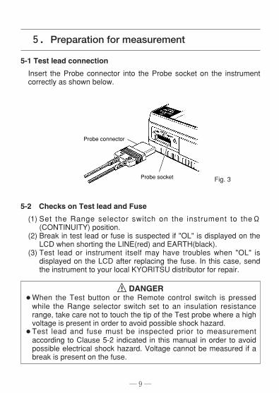
5-1 Test lead connection
Insert the Probe connector into the Probe socket on the instrumentcorrectly as shown below.
5-2 Checks on Test lead and Fuse
(1) Set the Range selector switch on the instrument to theΩ(CONTINUITY) position.
(2) Break in test lead or fuse is suspected if "OL" is displayed on theLCD when shorting the LINE(red) and EARTH(black).
(3) Test lead or instrument itself may have troubles when "OL" isdisplayed on the LCD after replacing the fuse. In this case, sendthe instrument to your local KYORITSU distributor for repair.
DANGER¡When the Test button or the Remote control switch is pressedwhile the Range selector switch set to an insulation resistancerange, take care not to touch the tip of the Test probe where a highvoltage is present in order to avoid possible shock hazard.
¡Test lead and fuse must be inspected prior to measurementaccording to Clause 5-2 indicated in this manual in order to avoidpossible electrical shock hazard. Voltage cannot be measured if abreak is present on the fuse.
― 9―
Probe socket
Probe connector
5.Preparation for measurement
Fig. 3
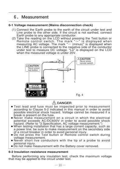
6-1 Voltage measurement (Mains disconnection check)
(1) Connect the Earth probe to the earth of the circuit under test andLine probe to the other side. If the circuit is not earthed, connectEarth probe to any appropriate conductor.
(2) Take the reading on the LCD without pressing the Test button orRemote control switch. The mark "~" is displayed whenmeasuring AC voltage. The mark "- (minus)" is displayed whenthe LINE probe is connected to the negative side of the conductorunder test to measure DC voltage. "Lo" is displayed on the LCDwhen the measured voltage is under 20V.
DANGER¡Test lead and fuse must be inspected prior to measurementaccording to Clause 5-2 indicated in this manual in order to avoidpossible electrical shock hazard. Voltage cannot be measured if abreak is present on the fuse.
¡Never make measurement on a circuit in which the electricalpotential exceeds AC/DC600V in order to avoid possible shockhazard. (Refer to "3.Specification, AC voltage measurement.")
¡When testing installation that has a large current capacity, such asa power line, be sure to make measurement on the secondary sideof a circuit breaker in order to avoid personal injury.
¡Do not press the Test button or Remote control switch duringvoltage measurement.
¡Never short live conductors with the tip of a probe to avoidpersonal injury.
¡Do not make measurement with the Battery cover removed.
6-2 Insulation resistance measurementBefore performing any insulation test, check the maximum voltage
that may be applied to the circuit under test.
― 10 ―
6.Measurement
CAUTION Never press test button
CAUTION Never press remote switcth
Fig. 4
― 11 ―
Note:¡Some circuits have an unstable insulation resistance, which causesthe reading to vary during measurement.
¡The instrument may generate a high pitch tone duringmeasurement. This is not a failure.
¡If the circuit under test has a large capacitive load, it may takesome time before the final reading can be obtained.
¡On insulation resistance range, DC voltage is supplied throughearth and Line probes, with earth probe having positive polarity.
Earth probe should be connected to the earth conductor in the circuitunder test. Such connection is known to be more suitable forinsulation tests since an insulation resistance value measured withthe positive side connected to earth is typically less than that takenthrough the reversed connection.
DANGER¡When the Test button or Remote control switch is pressed with theRange selector switch set to an insulation resistance rangeposition, take care not to touch the tip of the test probe or thecircuit under test where a high voltage is present in order to avoidpossible shock hazard.
¡Do not make measurement with the Battery cover removed.
CAUTION¡Ensure that the circuit under test is de-energized prior to anyinsulation testing.
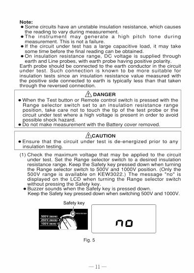
(1) Check the maximum voltage that may be applied to the circuitunder test. Set the Range selector switch to a desired insulationresistance range. Keep the Safety key pressed down when turningthe Range selector switch to 500V and 1000V position. (Only the500V range is available on KEW3022.) The message "no" isdisplayed on the LCD when turning the Range selector switchwithout pressing the Safety key.
¡Buzzer sounds when the Safety key is pressed down. Keep the Safety key pressed down when switching 500V and 1000V.
Fig. 5
― 12 ―
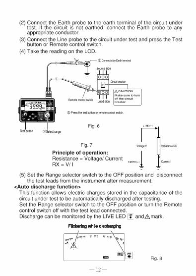
(5) Set the Range selector switch to the OFF position and disconnectthe test leads from the instrument after measurement.
<Auto discharge function>This function allows electric charges stored in the capacitance of thecircuit under test to be automatically discharged after testing.Set the Range selector switch to the OFF position or turn the Remotecontrol switch off with the test lead connected. Discharge can be monitored by the LIVE LED and mark.
(2) Connect the Earth probe to the earth terminal of the circuit undertest. If the circuit is not earthed, connect the Earth probe to anyappropriate conductor.
(3) Connect the Line probe to the circuit under test and press the Testbutton or Remote control switch.
(4) Take the reading on the LCD.
Principle of operation:Resistance = Voltage/ CurrentRX = V/ I
Fig. 6
Fig. 7
Fig. 8
(6) Set the Range selector switch to the OFF position, and disconnectthe probes from the instrument.
DANGER¡Never touch the circuit under test immediately after testing.Capacitance stored in the circuit may cause electric shock. Leave the test leads connected to the circuit until the LIVE LEDand LIVE circuit warning stop flickering.
6-3 Continuous measurementFor continuous measurement, a lock-down feature is incorporated onthe Test button. Pressing and turning clockwise locks the button inthe operating posit ion, the button is released by turning itcounterclockwise.
DANGER¡While the Test button is locked down, a high voltage is present atthe tip of a probe. Attention should be paid to avoid possible shockhazard.
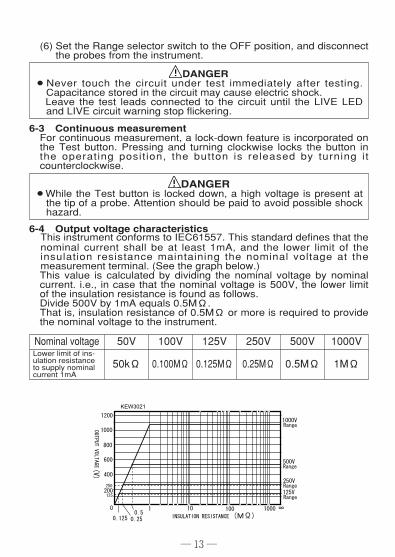
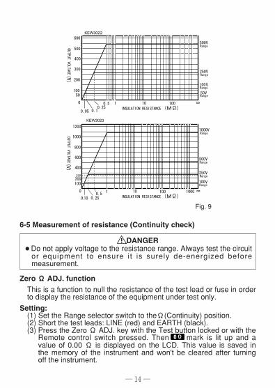
6-4 Output voltage characteristicsThis instrument conforms to IEC61557. This standard defines that thenominal current shall be at least 1mA, and the lower limit of theinsulation resistance maintaining the nominal voltage at themeasurement terminal. (See the graph below.)This value is calculated by dividing the nominal voltage by nominalcurrent. i.e., in case that the nominal voltage is 500V, the lower limitof the insulation resistance is found as follows. Divide 500V by 1mA equals 0.5MΩ.That is, insulation resistance of 0.5MΩ or more is required to providethe nominal voltage to the instrument.
― 13 ―
Nominal voltage
1MΩ
1000V
0.5MΩ
500V
0.25MΩ
250V
0.125MΩ
125V
0.100MΩ
100V
50kΩ
50VLower limit of ins-ulation resistanceto supply nominalcurrent 1mA
― 14 ―
6-5 Measurement of resistance (Continuity check)
DANGER¡Do not apply voltage to the resistance range. Always test the circuitor equipment to ensure it is surely de-energized beforemeasurement.
Zero Ω ADJ. functionThis is a function to null the resistance of the test lead or fuse in orderto display the resistance of the equipment under test only.Setting:(1) Set the Range selector switch to theΩ(Continuity) position.(2) Short the test leads: LINE (red) and EARTH (black).(3) Press the Zero Ω ADJ. key with the Test button locked or with theRemote control switch pressed. Then mark is lit up and avalue of 0.00 Ω is displayed on the LCD. This value is saved inthe memory of the instrument and won't be cleared after turningoff the instrument.
Fig. 9
Releasing:(1) Set the Range selector switch to theΩ(Continuity) position.(2) Open the test leads: LINE (red) and EARTH (black).(3) Press the Zero Ω ADJ. key to release this function when "OL" isdisplayed on the LCD while the Test button is locked or theRemote control switch is pressed down .
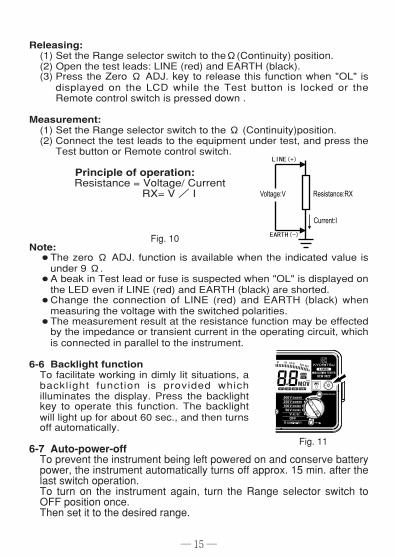
Measurement:(1) Set the Range selector switch to the Ω (Continuity)position.(2) Connect the test leads to the equipment under test, and press theTest button or Remote control switch.
Principle of operation:Resistance = Voltage/ Current
RX= V / I
Note:¡The zero Ω ADJ. function is available when the indicated value isunder 9 Ω.
¡A beak in Test lead or fuse is suspected when "OL" is displayed onthe LED even if LINE (red) and EARTH (black) are shorted.
¡Change the connection of LINE (red) and EARTH (black) whenmeasuring the voltage with the switched polarities.
¡The measurement result at the resistance function may be effectedby the impedance or transient current in the operating circuit, whichis connected in parallel to the instrument.
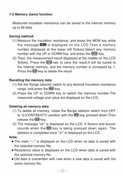
6-6 Backlight functionTo facilitate working in dimly lit situations, abacklight function is provided whichilluminates the display. Press the backlightkey to operate this function. The backlightwill light up for about 60 sec., and then turnsoff automatically.
6-7 Auto-power-offTo prevent the instrument being left powered on and conserve batterypower, the instrument automatically turns off approx. 15 min. after thelast switch operation.To turn on the instrument again, turn the Range selector switch toOFF position once.Then set it to the desired range.
― 15 ―
Fig. 10
Fig. 11
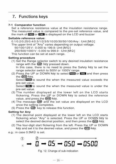
7-1 Comparator functionSet a reference resistance value at the insulation resistance range.The measured value is compared to the pre-set reference value, andthe mark of or is displayed on the LCD and buzzerSettable reference value:0.1/0.2/0.25/0.4/0.5/1/2/3/5/10/20/30/50/100/Any : Unit [MΩ]The upper limit of "Any" varies depending on output voltage.50/100/125V: 0.000 to 199.9: Unit [MΩ]250/500/1000V: 0.000 to 999.9 : Unit [MΩ]This function can be set at each range.Setting procedure(1) Set the Range selector switch to any desired insulation resistancerange with the key pressed down.In this case, there is no need to press the Safety key to set therange selector switch to 500V or 1000V range.
(2) Press the UP or DOWN key to select or and then pressthe key.Select to sound the when the measured value exceeds thepre-set value.Select to sound the when the measured value is under thepre-set value.
(3) The number displayed at the lower left on the LCD startsflickering. Press the UP or DOWN key to select the referencevalue, and press the key.
(4) The message and the set value are displayed on the LCDonce the setting completes.
(5) Press the key to release this function.Setting for Any(1) The decimal point displayed at the lower left on the LCD startsflickering when "Any" is selected. Press the UP or DOWN key toselect the desired decimal position, and then press the key.
(2) The four-digit start flickering from the left. Press the UP or DOWNkey and set it to the desired value, and press the key.
e.g.: in case 0.5MΩ is set.
― 16 ―
7.Functions keys
Fig. 12. Change of sub-indication
― 17 ―
7-2 Memory (save) function
Measured insulation resistance can be saved to the internal memoryup to 99 data.
Saving method:(1) Measure the insulation resistance, and press the MEM key whilethe message is displayed on the LCD.Then a memorynumber displayed at the lower left flickers.Select any memorynumber with the UP or DOWN key, and press the key.
(2) Then, the measurement result displayed at the middle on the LCDflickers. Press the key to save the result.It will be saved tothe internal memory, and the memory number is increased by 1.Press the key to delete the result.
Recalling the memory data(1) Set the Range selector switch to any desired Insulation resistancerange, and press the key.
(2) Press the UP or DOWN key to switch the memory number.Themeasured voltage and value are displayed on the LCD.
Deleting all memory data(1) To delete all memory, rotate the Range selector switch from OFFto Ω(CONTINUITY) position with the key pressed down.Thenrelease the key.
(2) The message "clr" is displayed on the LCD. It flickers and buzzersounds when the key is being pressed down again. Thedeletion is completed once "Ω" is displayed on the LCD.
Note:¡The mark "---" is displayed on the LCD when no data is saved withthe selected memory No.
¡Resistance value is displayed on the LCD when data is saved withthe selected memory No.
¡Old data is overwritten with new when a new data is saved with thesame memory No.
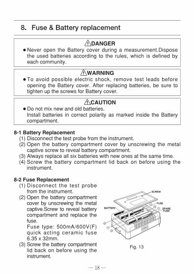
DANGER¡Never open the Battery cover during a measurement.Disposethe used batteries according to the rules, which is defined byeach community.
WARNING¡To avoid possible electric shock, remove test leads beforeopening the Battery cover. After replacing batteries, be sure totighten up the screws for Battery cover.
CAUTION¡Do not mix new and old batteries.Install batteries in correct polarity as marked inside the Batterycompartment.
8-1 Battery Replacement(1) Disconnect the test probe from the instrument.(2) Open the battery compartment cover by unscrewing the metalcaptive screw to reveal battery compartment.
(3) Always replace all six batteries with new ones at the same time.(4) Screw the battery compartment lid back on before using theinstrument.
8-2 Fuse Replacement(1) Disconnect the test probefrom the instrument.
(2) Open the battery compartmentcover by unscrewing the metalcaptive.Screw to reveal batterycompartment and replace thefuse.Fuse type: 500mA/600V(F)quick acting ceramic fuse6.35 x 32mm.
(3) Screw the battery compartmentlid back on before using theinstrument.
― 18 ―
Fig. 13
8.Fuse & Battery replacement
BATTERY
SCREW
FUSE
SPARE FUSE
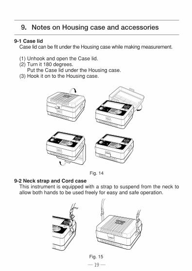
9-1 Case lidCase lid can be fit under the Housing case while making measurement.
(1) Unhook and open the Case lid.(2) Turn it 180 degrees.Put the Case lid under the Housing case.
(3) Hook it on to the Housing case.
9-2 Neck strap and Cord caseThis instrument is equipped with a strap to suspend from the neck toallow both hands to be used freely for easy and safe operation.
― 19 ―
9.Notes on Housing case and accessories
Fig. 14
Fig. 15
― 20 ―
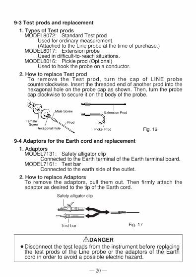
9-4 Adaptors for the Earth cord and replacement1. AdaptorsMODEL7131: Safety alligator clip
Connected to the Earth terminal of the Earth terminal board.MODEL7161: Test bar
Connected to the earth side of the outlet.2. How to replace AdaptorsTo remove the adaptors, pull them out. Then firmly attach theadaptor as desired to the tip of the Earth cord.
Female Screw
Male Screw
Prod
Pickel Prod
Extension Prod
Hexagonal Hole
9-3 Test prods and replacement1. Types of Test prodsMODEL8072: Standard Test prod
Used for ordinary measurement.(Attached to the Line probe at the time of purchase.)
MODEL8017: Extension probeUsed in difficult-to-reach situations.
MODEL8016: Pickle prod (Optional)Used to hook the probe on a conductor.
2. How to replace Test prodTo remove the Test prod, turn the cap of LINE probecounterclockwise. Insert the threaded end of another prod into thehexagonal hole on the probe cap as shown. Then, turn the probecap clockwise to secure it on the body of the probe.
Fig. 16
Fig. 17
Safety alligator clip
Test bar
DANGER¡Disconnect the test leads from the instrument before replacingthe test prods of the Line probe or the adaptors of the Earthcord in order to avoid a possible electric hazard.
― 21 ―
Cleaning Meter cover¡When cleaning the instrument, wipe it with a silicon cloth or softcloth to remove dust or dirt.
¡When it is hard to remove the dirt, wipe it with a cloth wet withwater and dry the instrument completely after cleaning.
CAUTION
¡Never use any solvent which may transmute plastics, forexample, organic solvent such as benzene, acetone, etc.
10.Cleaning of the instrument
If this tester should fail to operate correctly, return it to yournearest distributors stating the exact nature of the fault.Before returning the instrument, make sure that:a) Operating instructions have been followed.b) Test Leads have been inspected.c) Fuse has been checked.d) Battery has been checked.e) The unit is returned with all accessory leads.Remember, the more information written about the fault, thequicker it will be serviced.
11.Servicing
DISTRIBUTOR
KYORITSU ELECTRICALINSTRUMENTSWORKS, LTD.No.5-20, Nakane 2-chome,Meguro-ku,Tokyo, 152-0031 JapanPhone:81-3-3723-0131 Fax:81-3-3723-0152URL:http://www.kew-ltd.co.jpE-mail:[email protected]:Uwajima & Ehime
04-12 92-1635A