Embed Size (px)
Citation preview
INSTRUCTION AND MAINTENANCE MANUAL MARWIN UT DESIGN 2011 PNEUMATIC ACTUATORS
3170 Wasson Road * Cincinnati, OH 45209 USA Phone 513-533-5600 * Fax 513-871-0105 e-mail: [email protected] –www.marwinvalve.com
Page 1 of 10
Bulletin IM-UT Dsgn2011_1114
Note: the numbers in parenthesis refer to the components in the exploded view of page 3 for UT-0 thru UT-6.5 and page 4 for UT-7 and UT-8.
CAUTION: Remove dust from the actuator that may cause sparks; clean periodically to prevent accumulation of dust on the actuator. Do not hit the actuators with metallic objects, as this may give off sparks.
TABLE OF CONTENTS: 1. WARNING 2. SERVICE CONDITIONS 3. FUNCTION 4. STORAGE 5. MAINTENANCE 6. EXPLODED VIEW 7. DISASSEMBLING 8. ASSEMBLING 9. ADJUSTMENT 10. REVERSING PISTONS 11. IDENTIFICATION OF ACTUATOR VERSIONS
1 Warning
• The installation and the maintenance of pneumatic actuators must be assigned to trained and qualified personnel. • The use of the actuators outside the allowed temperature and pressure ranges may cause damage to the internal and external components. • Prior to any installation and maintenance of the actuator, shut-off and disconnect any kind of power or air supply. • Disassembling spring return type actuators may cause severe injuries due to compressed springs inside. The maintenance must be performed by
qualified expert personnel in full observance of the instruction described at paragraph 6. Otherwise the actuator has to be returned to MARWIN.
2 Service conditions
• AIR SUPPLY: dehumidified or lubricated air (standard). Other non-corrosive gases or fluids are a possible alternative option, if compatible to the materials of the actuator components (internal parts and lubricant).
• WORKING PRESSURE: 40 psi minimum to 115 psi maximum (2,7 bar minimum t o 8 bar maximum • TEMPERATURE:
- STANDARD: - 4°F to + 185°F (-20°C to + 85°C) - NBR gaskets, Kluber Tribostar 1 EP (Centoplex2 EP) Lithium / Mineral grease - HIGH temperature option: - 4°F to +302°F (-20°C to +150°C) - FKM (Viton) gaskets, Kluber Petamo GHY 133N Polyurea / Mineral grease - LOW temperature option: - 40°F to +185°F (-40°C to +85°C) - silicone gaskets, Kluber Isoflex Topas NB52 barium Complex / Synthetic grease Notes:
1. For high or low temperature options, special grease is used as the lubricant and may alter the torque generated by the actuator. For further information please refer to MARWIN.
2. Mixing grease types is not recommended. • ROTATION: 0°- 90°, adjustable ±5° in both end positions (double adjustment). • LUBRICATION: The actuators are equipped with filled-for-life lubrication for normal service conditions. • OPERATING TIME: Refer to the technical documentation. The operating time depends on v a r i o u s parameters such as air supply pressure,
capacity of the air supply installation (size of piping and control equipment), type of valve and fluid, selected safety factor, temperature etc.

INSTRUCTION AND MAINTENANCE MANUAL MARWIN UT DESIGN 2011 PNEUMATIC ACTUATORS
Page 2 of 10
Bulletin IM-UT Dsgn2011_1114
Bulletin IM-UT 2011 Dsgn - 1112
3170 Wasson Road * Cincinnati, OH 45209 USA Phone 513-533-5600 * Fax 513-871-0105 e-mail: [email protected] –www.marwinvalve.com
3 Function
The air pressure acts on the surface of the pistons (12) causing their alternate movement, which is converted into rotation (standard 90°) of the pinion (2). As a result the pneumatic actuators can be used for remote operation of valves.
3.1 Double acting (Standard execution shown – top view)
CLOSED OPEN
P1 (IN AIR) P2 (IN AIR)
Supplying air through port P1, the external chambers fill up and the action of the pressure on the surface of the pistons (12) creates a force (F) pushing them toward each other, generating a torque with CLOCKWISE rotation.
3.2 Spring return
When the pistons (12) are close to the pinion, supplying air through port P2 the internal chamber fills up and the pressure on the surface of the pistons creates a force (F1) pushing them away from each other, generating a torque with COUNTERCLOCKWISE rotation.
OPEN CLOSED
P2 (IN AIR)
Supplying air through port P2, the internal chamber fills up and the action of the pressure on the surface of the pistons (12) creates a force (F1) pushing them away from each other, generating a torque with COUNTERCLOCKWISE rotation.
4 Storage
The springs (M) are now compressed. Venting the air out of the internal chamber through port P2 allows the springs (M) t o start extending and apply a force (Fm) on the pistons (12) pushing them toward each other, generating a torque with CLOCKWISE rotation.
It is recommended that the actuator be kept in clean and dry place. The state of preservation during the storage time is improved if the actuator is preserved in the original packing box. For a long storage period we recommend to periodically stroke the actuator one complete cycle by pressurizing the chambers.
The actuators have two air ports which should be plugged during storage to avoid intrusion of contaminants.
5 Maintenance
Maintenance should be performed by Marwin or other properly trained personnel. Marwin supplies spare parts (gaskets, guide elements) in appropriate kits (except for lubricating grease). Maintenance may become necessary between 500,000 and 1,000,000 cycles, depending upon local service conditions.
P2 (OUT AIR)
(Standard execution shown – top view)
2
F1 F1 12
F1
2
12
F1
12
2
m (Springs)
Fm
Fm
12 F1
2 F1
INSTRUCTION AND MAINTENANCE MANUAL MARWIN UT DESIGN 2011 PNEUMATIC ACTUATORS
Page 3 of 10
Bulletin IM-UT Dsgn2011_1114
3170 Wasson Road * Cincinnati, OH 45209 USA Phone 513-533-5600 * Fax 513-871-0105 e-mail: [email protected] –www.marwinvalve.com
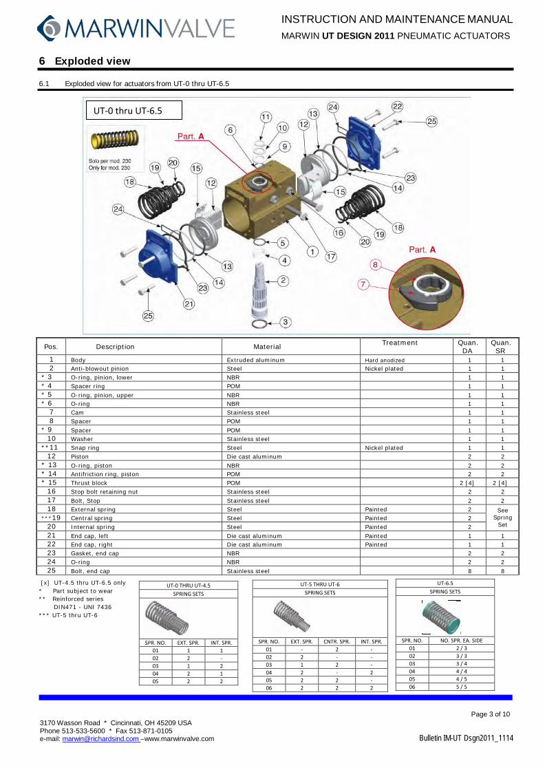
6 Exploded view
6.1 Exploded view for actuators from UT-0 thru UT-6.5
Pos. Description Material Treatment Quan. DA
Quan. SR
1 Body Extruded aluminum Hard anodized 1 1 2 Anti-blowout pinion Steel Nickel plated 1 1
* 3 O-ring, pinion, lower NBR 1 1 * 4 Spacer ring POM 1 1 * 5 O-ring, pinion, upper NBR 1 1 * 6 O-ring NBR 1 1
7 Cam Stainless steel 1 1 8 Spacer POM 1 1
* 9 Spacer POM 1 1 10 Washer Stainless steel 1 1
**11 Snap ring Steel Nickel plated 1 1 12 Piston Die cast aluminum 2 2
* 13 O-ring, piston NBR 2 2 * 14 Antifriction ring, piston POM 2 2 * 15 Thrust block POM 2 [4] 2 [4]
16 Stop bolt retaining nut Stainless steel 2 2 17 Bolt, Stop Stainless steel 2 2 18 External spring Steel Painted 2 See
Spring Set
***19 Central spring Steel Painted 2 20 Internal spring Steel Painted 2 21 End cap, left Die cast aluminum Painted 1 1 22 End cap, right Die cast aluminum Painted 1 1 23 Gasket, end cap NBR 2 2 24 O-ring NBR 2 2 25 Bolt, end cap Stainless steel 8 8
[x] UT-4.5 thru UT-6.5 only * Part subject to wear ** Reinforced series
DIN471 - UNI 7436 *** UT-5 thru UT-6
UT-0 THRU UT-4.5 SPRING SETS
SPR. NO. EXT. SPR. INT. SPR. 01 1 1 02 2 - 03 1 2 04 2 1 05 2 2
UT-5 THRU UT-6 SPRING SETS
SPR. NO. EXT. SPR. CNTR. SPR. INT. SPR. 01 - 2 - 02 2 - - 03 1 2 - 04 2 - 2 05 2 2 - 06 2 2 2
UT-6.5 SPRING SETS
SPR. NO. NO. SPR. EA. SIDE 01 2 / 3 02 3 / 3 03 3 / 4 04 4 / 4 05 4 / 5 06 5 / 5
UT-0 thru UT-6.5

INSTRUCTION AND MAINTENANCE MANUAL MARWIN UT DESIGN 2011 PNEUMATIC ACTUATORS
Page 4 of 10
Bulletin IM-UT Dsgn2011_1112
3170 Wasson Road * Cincinnati, OH 45209 USA Phone 513-533-5600 * Fax 513-871-0105 e-mail: [email protected] –www.marwinvalve.com
6.2 Exploded view mod. UT-7 and UT-7.5
Pos. Description Material Treatment Quan. DA
Quan. SR
1 Body Extruded aluminum Hard anodized 1 1 2 Pinion, anti-blowout Steel Nickel plated 1 1
* 3 O-ring, pinion, lower NBR 1 1 * 4 O-ring, pinion, upper NBR 1 1 * 5 Antifriction ring, pinion PTFE 15% graphite 1 1 * 6 Antifriction ring, pinion PTFE 1 1
7 Housing, stop assembly GGG40 Painted 1 1 8 Washer Stainless steel 4 8 9 Nut, stop bolt retaining Stainless steel 2 2
10 Bolt, stop Steel Zinc plated 2 2 11 Bolt, housing, stop assembly Stainless steel 4 [8] 4 [8] 12 Piston Die cast aluminum 2 2 13 Spring, pre-compressed Steel Painted See Spring Set 14 Bolt, end cap Stainless steel 12 [16] 12 [16] 15 End cap Die cast aluminum Painted 2 2
* 16 Thrust block POM 6 [8] 6 [8] * 17 Spacer ring POM 1 1
18 Washer, pinion Stainless steel 1 1 19 Snap ring Steel Nickel plated 1 1
* 20 O-ring, pinion NBR 2 2 * 21 Antifriction ring PTFE 15% graphite 2 2
22 O-ring, end cap NBR 2 2 23 O-ring NBR 4 [2] 4 [2] 24 Anti-blowout key POM 2 2
[x] UT-7 only * Part subject to wear
UT-7 THRU 7.5 SPRING SETS
SPR. NO. NO. SPR. EA. SIDE 01 2 / 3 02 3 / 3 03 3 / 4 04 4 / 4 05 4 / 5 06 5 / 5 06 5 / 6 07 6 / 6
UT-7 THRU UT-7.5
INSTRUCTION AND MAINTENANCE MANUAL MARWIN UT DESIGN 2011 PNEUMATIC ACTUATORS
Page 5 of 10
Bulletin IM-UT Dsgn2011_1114
3170 Wasson Road * Cincinnati, OH 45209 USA Phone 513-533-5600 * Fax 513-871-0105 e-mail: [email protected] –www.marwinvalve.com
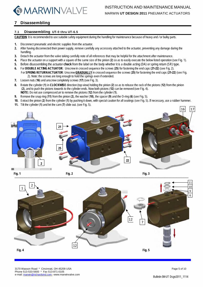
7 Disassembling
7.1 Disassembling UT-0 thru UT-6.5
CAUTION: It is recommended to use suitable safety equipment during the handling for maintenance because of heavy and / or bulky parts.
1. Disconnect pneumatic and electric supplies from the actuator. 2. After having disconnected their power supply, remove carefully any accessory attached to the actuator, preventing any damage during the
handling. 3. Detach the actuator from the valve taking carefully note of all references that may be helpful for the attachment after maintenance. 4. Place the actuator on a support with a square of the same size of the pinion (2) so as to easily execute the below listed operation (see Fig. 1). 5. Before disassembling the actuator check from the label on the body whether it is a double acting (DA) or spring return (SR) type. 6. For DOUBLE ACTING ACTUATOR: Unscrew in crossed sequence the screws (25) for fastening the end caps (21-22) (see Fig. 2).
For SPRING RETURN ACTUATOR: Unscrew GRADUALLY in crossed sequence the screws (25) for fastening the end caps (21-22) (see Fig. 2). Note: the screws are long enough to hold the springs even if extended.
7. Loosen nuts (16) and unscrew completely screws (17) (see Fig. 3). 8. Rotate the cylinder (1) in CLOCKWISE direction (top view) holding the pinion (2) so as to release the rack of the pistons (12) from the pinion
(2), and to push the pistons towards to the cylinder ends. Now both pistons (12) can be removed (see Fig. 4). NOTE: Do not use compressed air to remove the pistons (12) from the cylinder (1).
9. Remove the snap ring (11) from the pinion (2), the washer (10), the spacer (9) and the O-ring (6) (see Fig. 5). 10. Extract the pinion (2) from the cylinder (1) by pushing it down, with special caution for all seatings (see Fig. 5). If necessary, use a rubber hammer. 11. Tilt the cylinder (1) and let the cam (7) slide out. (see Fig. 5).
21
25
22 2
Fig. 1 Fig. 2 Fig. 3 ----------------------------------------------------------------------------------------------------------------------------------------------------------------------------------------------------
Fig. 4 Fig. 5
16 17
2 1
12
12
11
7
10 9 6
INSTRUCTION AND MAINTENANCE MANUAL MARWIN UT DESIGN 2011 PNEUMATIC ACTUATORS
Page 6 of 10
Bulletin IM-UT Dsgn2011_1114
3170 Wasson Road * Cincinnati, OH 45209 USA Phone 513-533-5600 * Fax 513-871-0105 e-mail: [email protected] –www.marwinvalve.com
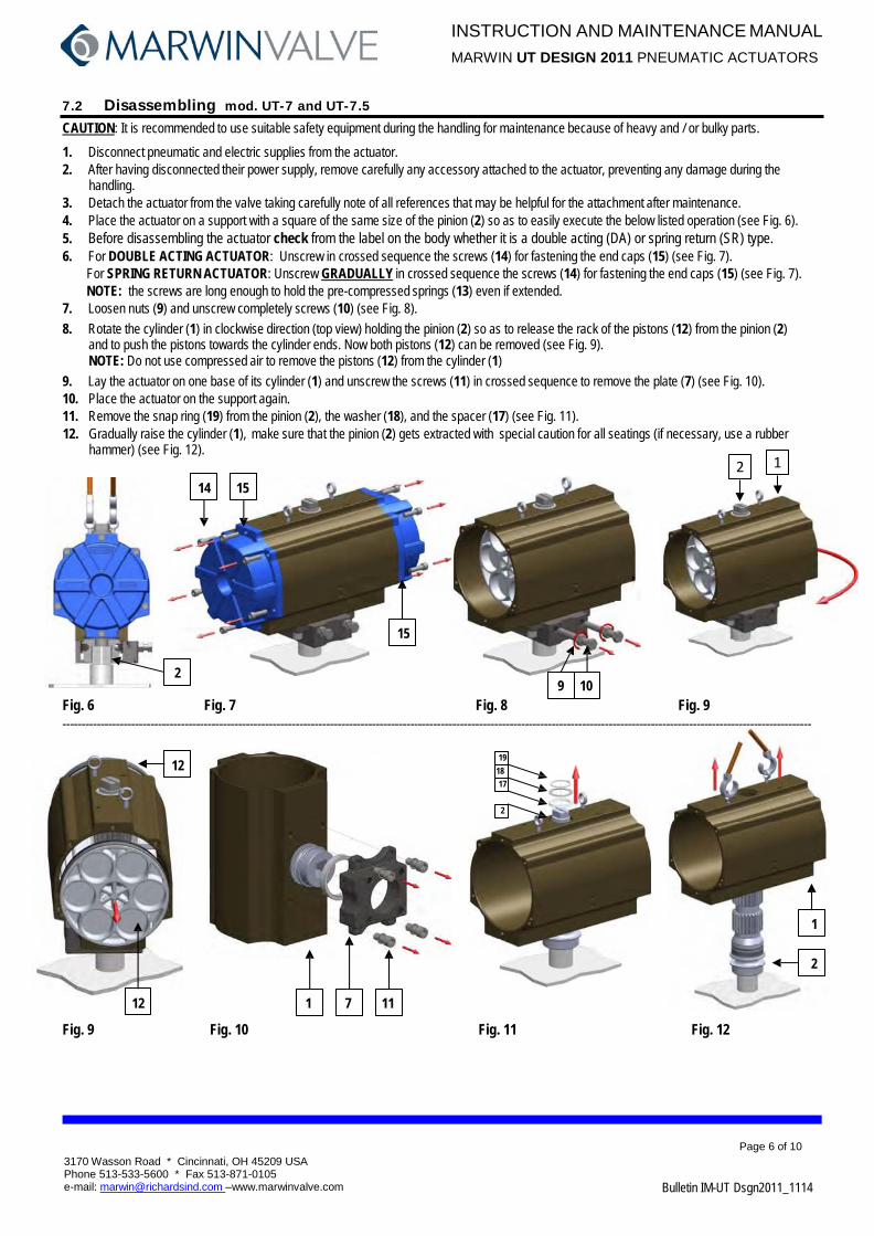
7.2 Disassembling mod. UT-7 and UT-7.5
CAUTION: It is recommended to use suitable safety equipment during the handling for maintenance because of heavy and / or bulky parts.
1. Disconnect pneumatic and electric supplies from the actuator. 2. After having disconnected their power supply, remove carefully any accessory attached to the actuator, preventing any damage during the
handling. 3. Detach the actuator from the valve taking carefully note of all references that may be helpful for the attachment after maintenance. 4. Place the actuator on a support with a square of the same size of the pinion (2) so as to easily execute the below listed operation (see Fig. 6). 5. Before disassembling the actuator check from the label on the body whether it is a double acting (DA) or spring return (SR) type. 6. For DOUBLE ACTING ACTUATOR: Unscrew in crossed sequence the screws (14) for fastening the end caps (15) (see Fig. 7).
For SPRING RETURN ACTUATOR: Unscrew GRADUALLY in crossed sequence the screws (14) for fastening the end caps (15) (see Fig. 7). NOTE: the screws are long enough to hold the pre-compressed springs (13) even if extended.
7. Loosen nuts (9) and unscrew completely screws (10) (see Fig. 8). 8. Rotate the cylinder (1) in clockwise direction (top view) holding the pinion (2) so as to release the rack of the pistons (12) from the pinion (2)
and to push the pistons towards the cylinder ends. Now both pistons (12) can be removed (see Fig. 9). NOTE: Do not use compressed air to remove the pistons (12) from the cylinder (1)
9. Lay the actuator on one base of its cylinder (1) and unscrew the screws (11) in crossed sequence to remove the plate (7) (see Fig. 10). 10. Place the actuator on the support again. 11. Remove the snap ring (19) from the pinion (2), the washer (18), and the spacer (17) (see Fig. 11). 12. Gradually raise the cylinder (1), make sure that the pinion (2) gets extracted with special caution for all seatings (if necessary, use a rubber
hammer) (see Fig. 12).
14 15
15
2 9 10
Fig. 6 Fig. 7 Fig. 8 Fig. 9 ----------------------------------------------------------------------------------------------------------------------------------------------------------------------------------------------------
19
12 18 17
2
1
2
12 1 7 11
Fig. 9 Fig. 10 Fig. 11 Fig. 12
1 2

INSTRUCTION AND MAINTENANCE MANUAL MARWIN UT DESIGN 2011 PNEUMATIC ACTUATORS
Page 7 of 10
3170 Wasson Road * Cincinnati, OH 45209 USA Phone 513-533-5600 * Fax 513-871-0105 e-mail: [email protected] –www.marwinvalve.com Bulletin IM-UT Dsgn2011_1114
8 Assembling 8.1 Assembling UT-0 thru UT-6.5
CAUTION: It is recommended to use suitable safety equipment during the handling for maintenance because of heavy and/or bulky parts.
1. Before assembling clean all components preferably with degreaser. 2. Place the pinion (2) on a support with a square of the same size of the female attachment. Make sure that the pinion is provided with
lower O-ring (3), spacer (4) and upper O-ring (5). Lubricate the O-rings (see arrows Fig. 13). The recommended lubricating grease is “KLUBER” TRIBO STAR 1EP“
3. Screw down one adjustment screw (17) with nut (16) in the right adjustment hole of the cylinder (1) and let the cam (7) with ring (8) slide down on the guiding rail on the cylinder (1) until it stops against the screw (see Fig.14 detail A) .
4. Lay the cylinder (1) down on the pinion (2) holding it with the NAMUR surface rotated by approximately 50° to the upper slot of the pinion, (see Fig.15).
5. Fit on the pinion (2) the O-ring (6), the spacer (9), the washer (10), the snap ring (11) (see Fig. 16). 6. Grease the internal chamber of the cylinder (1) and both pistons (12) provided with O-ring (13) antifriction ring (14) and thrust block (15) - The
recommended lubricating grease is “KLUBER” TRIBO STAR 1EP“. 7. For the standard execution (clockwise pinion rotation looking at top when pistons travel toward each other) press the pistons (12) into the cylinder
(1) while turning the cylinder (1) in counterclockwise direction (top view) until the pistons come into contact (see Fig. 17). 8. Screw down the second adjustment screw (17) with nut (16) in the cylinder (1) and adjust the travel stop (see paragraph 9). 9. For DOUBLE ACTING ACTUATOR: Mount the end cap (21-22) with O-ring (24) and gasket (23) on the cylinder and screw down in crossed
sequence the screws (25) (see Fig. 18). Repeat the operation on the opposite side. For SPRING RETURN ACTUATOR: Introduce the spring set (18-19-20) into the cylinder (1) and center them on the piston (12), then mount the
caps (21-22) with O-ring (24) and gaskets (23) centered on the springs (18-19-20). Note: the pistons have to be in CLOSED (contracted) position. Tighten the screws (25) a little at a time in a crossed sequence, compressing the springs uniformly, until the cap is completely closed (see Fig. 18). Repeat the operation on the opposite side.
10. Execute some test cycles to check the correct functioning of the actuator before installing it.
DET. A
5
4
16 17
1
10 11 9 6 2
2 1
2
3 7
8
Fig. 13 Fig. 14 Fig. 15 Fig. 16 -------------------------------------------------------------------------------------------------------------------------------------------------------------------------------------------------
Fig.17 Fig.18
22 23
25
21 16 17
24
13 14 15
12
1
12

INSTRUCTION AND MAINTENANCE MANUAL MARWIN UT DESIGN 2011 PNEUMATIC ACTUATORS
Page 8 of 10
Bulletin IM-UT Dsgn2011_1114
3170 Wasson Road * Cincinnati, OH 45209 USA Phone 513-533-5600 * Fax 513-871-0105 e-mail: [email protected] –www.marwinvalve.com
8.2 Assembling UT-7 and UT-7.5
CAUTION: It is recommended to use suitable safety equipment during the handling for maintenance because of heavy and / or bulky parts.
1. Before assembling clean all components preferably with degreaser. 2. Place the pinion (2) on a support with a square of the same size of the female attachment. Make sure that the pinion is provided with
lower O-ring (3), spacer (5) and upper O-ring (4). Lubricate the O-rings (see arrows Fig. 19). The recommended lubricating grease is “KLUBER” TRIBO STAR 1EP“
3. Lay the cylinder (1) down on the pinion (2) (see Fig. 20). 4. Fit on the pinion (2) the spacer (17), the washer (18), and the snap ring (19) (see Fig. 21). 5. Remove the cylinder with pinion from the support and lay it on one base to mount the plate (7) with antifriction ring (6), (holes for adjusting screws
on the same side as the NAMUR attachments) then screw down the fastening screws (11) with washer (8) in crossed sequence (see Fig. 22), and place the cylinder on the support again.
6. Grease the internal chamber of the cylinder (1) and both pistons (12) provided with O-ring (20) antifriction ring (21) anti blowout key (24) and thrust block (16) - The recommended lubricating grease is “KLUBER” TRIBO STAR 1EP“.
7. Rotate the cylinder (1) by approximately 50° to the upper slot of the pinion (see Fig. 23). 8. For the standard execution (clockwise pinion rotation looking at top when pistons travel toward each other) press the pistons (12) into the cylinder
(1) while turning the cylinder (1) in counterclockwise direction ( top view) until the pistons come into contact (see Fig. 23, 24). 9. Introduce the adjustment screws (10) with nut (9) into the plate (7) to adjust the travel stop (see Fig. 25 and paragraph 9). 10. For DOUBLE ACTING ACTUATOR: Mount the end cap (15) with O-ring (22-23) and gasket (23) on the cylinder and screw down in crossed
sequence the screws (25), see Fig. 18. Repeat the operation on the opposite side. For SPRING RETURN ACTUATOR: Introduce the spring set (13) into the cylinder (1) and center them on the piston (12), then mount the caps
(15) with O-ring (22-2) centered on the springs (13). Note: the pistons have to be in CLOSED (contracted) position. Tighten the screws (14) a little at a time in a crossed sequence, compressing the springs uniformly, until the cap (15) is completely closed (see Fig. 26). Repeat the operation on the opposite side.
11. Execute some test cycles to check the correct functioning of the actuator before installing it. 19 18 1 17
4 6 7
2
3
5 2
Fig. 19 Fig. 20 Fig. 21 Fig. 22 8 11
------------------------------------------------------------------------------------------------------------------------------------------------------------------------------------------------ 12
1 14 15
15 22
9
23 1
12 7 10
Fig. 23 Fig. 24 Fig. 25 Fig. 26
Drilling

INSTRUCTION AND MAINTENANCE MANUAL MARWIN UT DESIGN 2011 PNEUMATIC ACTUATORS
Page 9 of 10 3170 Wasson Road * Cincinnati, OH 45209 USA Phone 513-533-5600 * Fax 513-871-0105 e-mail: [email protected] –www.marwinvalve.com Bulletin IM-UT Dsgn2011_1114
9 Adjustment
The 90° position (open) can be adjusted with the left screw (see Fig. 27). The 0° position (closed) can be adjusted with the right screw (see Fig. 28).
L R L R
Fig. 27 Fig. 28 L R L R
NOTE: During the adjustment the pinion must not be blocked on the support.
9.1 Adjustment procedure, actuator in open position
• Put the actuator in closed position. • Adjust by means of the left adjustment screw (L). • Put the actuator in open position and check the adjustment • Repeat until the desired adjustment is achieved. • Hold the screw in the correct position and tighten the nut.
9.2 Adjustment procedure, actuator in closed position
• Put the actuator in open position (supply compressed air for spring return actuators). • Adjust by means of the right adjustment screw (R). • Put the actuator in closed position and check the adjustment (vent the air supply for spring return actuators). • Repeat until the desired adjustment is achieved. • Hold the screw in the correct position and tighten the nut.
10 Reversing Pistons Industry convention is Clockwise to Close, CounterClockwise to open quarter turn valves. Standard actuator execution is for the spring force to rotate the piston clockwise, which causes the valve to fail clockwise to close, in accordance with this convention. For fail open valves, pistons should be reversed for the spring force to rotate the piston counterclockwise to open the valve, in order to maintain the industry convention. To reverse the pistons, disassemble the actuator through Section 7.1 (UT-0 thru UT-6.5) or 7.2 (UT-7 and UT-7.5), step 8. It is not necessary to remove the pinion in order to reverse the pistons. Reassemble in accordance with Section 8.1 or 8.2, as applicable, except as follows: In step 7 or 8, put the pistons in opposite the orientation shown in Fig. 17 or Fig. 23, and rotate the cylinder (1) in the counterclockwise direction. In step 9 or 10, the pistons have to be in OPEN (contracted) position for spring insertion.

INSTRUCTION AND MAINTENANCE MANUAL MARWIN UT DESIGN 2011 PNEUMATIC ACTUATORS
Page 10 of 10 3170 Wasson Road * Cincinnati, OH 45209 USA Phone 513-533-5600 * Fax 513-871-0105 e-mail: [email protected] –www.marwinvalve.com Bulletin IM-UT Dsgn2011_1114
2011 Design (UT-1 Shown)
Representative of: UT actuators 0A thru 7.5 after about 2011
Distinguishing features: Adjusting screws on side, no hub on top, “squared” ends
I&M Bulletin IM-UT Dsgn2011_9999
2003 Design (UT-0 and UT-0A Shown)
Representative of: UT actuators 0 thru 4 after about 2003
Distinguishing features (UT-0 thru UT-4.5): Adjusting screws on side, hub on top, “squared” ends
Distinguishing features (UT-0A) Shorter shaft extension on top
I&M Bulletin IM-UT(2003Design)-1211
Pre 2003 Design (UT-0 and UT-0A Shown)
Representative of: All UT actuators 0A thru 7 prior to 2003 UT-0A, and UT-5 thru 7 only after 2003
Distinguishing features: No adjusting screws on side, no hub on top,
Rounded ends with adjusting screws I&M
Bulletin IM-UT(Pre2003Design)-1209