Embed Size (px)
Citation preview
Catalyst 478-14409-08
C H A P T E R 3
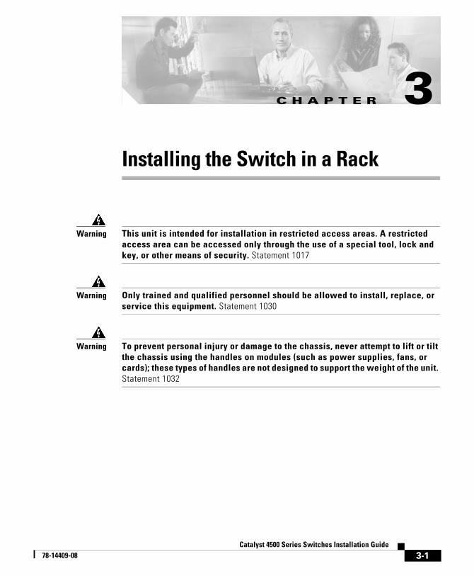
Installing the Switch in a RackWarning This unit is intended for installation in restricted access areas. A restricted access area can be accessed only through the use of a special tool, lock and key, or other means of security. Statement 1017
Warning Only trained and qualified personnel should be allowed to install, replace, or service this equipment. Statement 1030
Warning To prevent personal injury or damage to the chassis, never attempt to lift or tilt the chassis using the handles on modules (such as power supplies, fans, or cards); these types of handles are not designed to support the weight of the unit. Statement 1032
3-1500 Series Switches Installation Guide
Chapter 3 Installing the Switch in a Rack
Note The blank line card (C4K-SLOT-CVR-E) must be installed when either of the following two situations occur:
• If your Catalyst 4507R or Catalyst 4510R switch chassis has a Supervisor Engine 6-E (WS-X45-SUP6-E) or a Supervisor Engine 6L-E (WS-X45-SUP6L-E) installed in slot 1 and slot 2 is empty, you must install the blank line card (C4K-SLOT-CVR-E) in slot 2 rather than a blank faceplate (C4K-SLOT-CVR) . A blank faceplate covering the slot 2 opening does not direct sufficient airflow to adequately cool the Supervisor Engine 6-E or the Supervisor Engine 6L-E.
• If your Catalyst 4507R or Catalyst 4510R switch chassis has a Supervisor Engine 6-E (WS-X45-SUP6-E) or a Supervisor Engine 6L-E (WS-X45-SUP6L-E) installed in slot 2 and slot 1 is empty, you must install the blank line card (C4K-SLOT-CVR-E) in slot 1 rather than a blank faceplate (C4K-SLOT-CVR) . A blank faceplate covering the slot 1 opening does not direct sufficient airflow to adequately cool the Supervisor Engine 6-E or the Supervisor Engine 6L-E.
Note When populating empty chassis slots, start filling the upper slots first and work down to the bottom slots.
This chapter describes how to install Catalyst 4500 series switches in a rack. For first-time installations, perform the procedures in the following sections in the order listed:
• Checking the Shipping Container Contents, page 3-3
• Rack-Mounting the Switch, page 3-4
Note Before starting the installation procedures in this chapter, complete the site-planning checklist in Table 2-2 of Chapter 2, “Preparing for Installation.”
3-2Catalyst 4500 Series Switches Installation Guide
78-14409-08
Chapter 3 Installing the Switch in a RackChecking the Shipping Container Contents
Note For information on installing the supervisor engine and switching modules and verifying switch operation, refer to the Catalyst 4500 Series Module Installation Guide. For information on configuring the switching modules, refer to the software configuration guide for your switch and software release.
Checking the Shipping Container Contents
Note Do not discard the shipping cartons and poly bag when you unpack the switch. Flatten and store them. You will need the containers if you need to move or ship the switch in the future. Repacking instructions are provided in Appendix B, “Repacking a Switch.”
Follow these steps to check the contents of the shipping cartons:
Step 1 Check the contents of the accessories box against the Accessories Box Components Checklist and the packing slip that were included with your switch. Verify that you received all listed equipment, including the following:
• Switch hardware documentation and software documentation (if ordered)
• Optional equipment that you ordered, such as network interface cables, transceivers, or special connectors
Step 2 Check the switching modules in each slot. Ensure that the configuration matches the packing list and that all the specified interfaces are included.
3-3Catalyst 4500 Series Switches Installation Guide
78-14409-08
Chapter 3 Installing the Switch in a RackRack-Mounting the Switch
Rack-Mounting the SwitchA standard rack-mount kit is included for mounting the switch in a standard 19-inch (48.3 cm) equipment rack with two unobstructed outer posts, with a nominal depth (between the front and rear mounting posts) of 19.25 inches (48.9 cm) and a maximum depth of 32 inches (81.3 cm). This kit is not suitable for racks with obstructions (such as a power strip) that could impair access to the field-replaceable units (FRUs) of the switch.
Alternatively, you can obtain a 23-inch rack-mount kit.
Required Installation ToolsYou will need the following tools and equipment to install the chassis in a rack:
• Number 1 and number 2 Phillips screwdrivers to tighten the captive installation screws on most systems
• 3/16-inch flat-blade screwdriver for the captive installation screws on the supervisor engine and switching modules on some systems
• Antistatic mat or antistatic foam in case you need to remove switching modules to troubleshoot the installation
• Rack-mount kit
• Tape measure
• Level
• Your own electrostatic discharge (ESD) grounding strap or the disposable ESD strap included with the system
3-4Catalyst 4500 Series Switches Installation Guide
78-14409-08
Chapter 3 Installing the Switch in a RackRack-Mounting the Switch
Rack-Mounting Catalyst 4500 Series Switches
Follow these steps to install a Catalyst 4500 series switch in a rack:
Step 1 Prepare for installation as follows:
a. Place the chassis on the floor or on a sturdy table as close as possible to the rack. Leave enough clearance to allow you to move around the chassis.
b. Use a tape measure to measure the depth of the rack. Measure from the outside of the front mounting posts to the outside of the rear mounting strip. The depth must be at least 19.25 inches (48.9 cm) but not greater than 32 inches (81.3 cm).
c. Measure the space between the inner edges of the left front and right front mounting posts to ensure that it is 17.75 inches (45.09 cm) wide. (The chassis is 17.25 inches [43.8 cm] wide and must fit between the mounting posts.)
d. Open the rack-mount kit and check the component checklist in Table 3-1 to verify that all parts are included.
Warning To prevent bodily injury when mounting or servicing this unit in a rack, you must take special precautions to ensure that the system remains stable. The following guidelines are provided to ensure your safety:
• This unit should be mounted at the bottom of the rack if it is the only unit in the rack.
• When mounting this unit in a partially filled rack, load the rack from the bottom to the top with the heaviest component at the bottom of the rack.
• If the rack is provided with stabilizing devices, install the stabilizers before mounting or servicing the unit in the rack. Statement 1006
3-5Catalyst 4500 Series Switches Installation Guide
78-14409-08
Chapter 3 Installing the Switch in a RackRack-Mounting the Switch
Note Some equipment racks provide a power strip along the length of one of the rear posts. If your rack has this feature, consider the position of the strip when planning fastener points. Before installing the L brackets on the chassis, determine whether to install the chassis from the front or the rear of the rack.
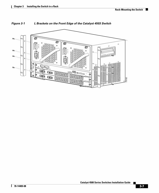
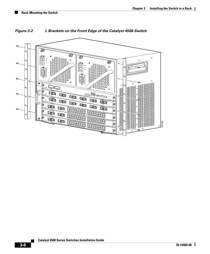
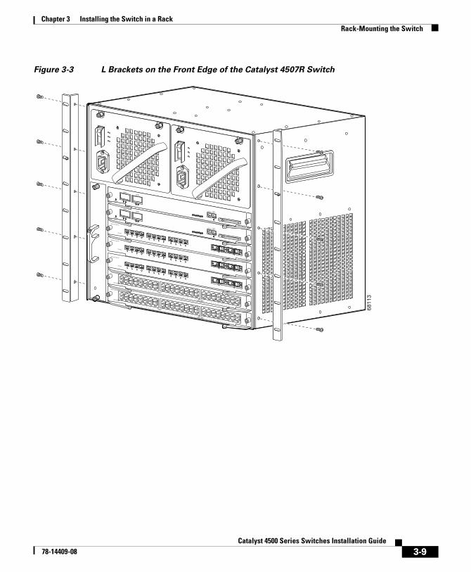
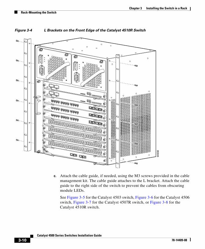
Step 2 Install the L brackets, which connect the chassis to the rack, as follows:
a. Remove the screws from the front of the switch side-cover panels.
b. Attach the left and right L brackets using the six M4 Phillips pan-head screws (three screws per side) provided in the rack-mount kit.
See Figure 3-1 for the Catalyst 4503 switch, Figure 3-2 for the Catalyst 4506 switch, or Figure 3-3 for the Catalyst 4507R switch, or Figure 3-4 for the Catalyst 4510R switch.
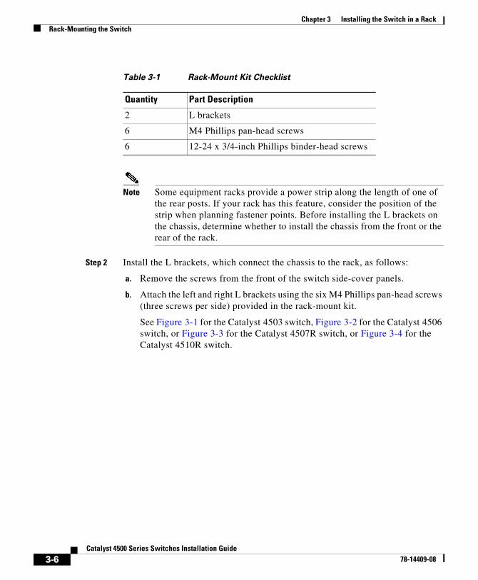
Table 3-1 Rack-Mount Kit Checklist
Quantity Part Description
2 L brackets
6 M4 Phillips pan-head screws
6 12-24 x 3/4-inch Phillips binder-head screws
3-6Catalyst 4500 Series Switches Installation Guide
78-14409-08
Chapter 3 Installing the Switch in a RackRack-Mounting the Switch
Figure 3-1 L Brackets on the Front Edge of the Catalyst 4503 Switch
1
13
1
13
1
13
1
13
7918
2
4506UPLINK 1
UPLINK 2
ACTIVE
LINE ACTIVELINE ACTIVE
RESET
UTILIZATION
STATUS
4503
WS-X4515 SUPERVISOR ENGINE IV
1%
100%
CONSOLE
LINKEJECT
FLASH
10/100MGT
3-7Catalyst 4500 Series Switches Installation Guide
78-14409-08
Chapter 3 Installing the Switch in a RackRack-Mounting the Switch
Figure 3-2 L Brackets on the Front Edge of the Catalyst 4506 Switch
1
13
1
13
1
13
1
13
1
13
1
13
7918
3
UPLINK 1
UPLINK 2
ACTIVE
LINE ACTIVELINE ACTIVE
RESET
UTILIZATION
STATUS
WS-X4515 SUPERVISOR ENGINE IV
1%
100%
CONSOLE
LINKEJECT
FLASH
10/100MGT
3-8Catalyst 4500 Series Switches Installation Guide
78-14409-08
Chapter 3 Installing the Switch in a RackRack-Mounting the Switch
Figure 3-3 L Brackets on the Front Edge of the Catalyst 4507R Switch
6811
3
WS-X4448-GB-RJ45
STATUS
121110987654321
1413
1615
282726252423222120191817
3029
3231
444342414039383736353433
4645
4847
10/100BASE-TXETHERNET
MULTI-SPEEDGIGABIT ETHERNETSWITCHING MODULE
WS-X4448-GB-RJ45
STATUS
121110987654321
1413
1615
282726252423222120191817
3029
3231
444342414039383736353433
4645
4847
10/100BASE-TXETHERNET
MULTI-SPEEDGIGABIT ETHERNETSWITCHING MODULE
1
STATUS
WS-X4412-2GB-TX
23
45
67
89
1011
12
17
1
STATUS
WS-X4412-2GB-TX
23
45
67
89
1011
12
17
1
STATUS
WS-X4412-2GB-TX
23
45
67
89
1011
12
17
UPLINKUPLINK
CONSOLE 10/100BASE-TX
STATUS
UPLINKUPLINK
CONSOLE 10/100BASE-TX
STATUS
3-9Catalyst 4500 Series Switches Installation Guide
78-14409-08
Chapter 3 Installing the Switch in a RackRack-Mounting the Switch
Figure 3-4 L Brackets on the Front Edge of the Catalyst 4510R Switch
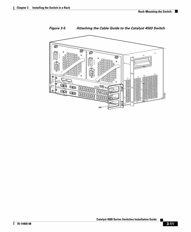
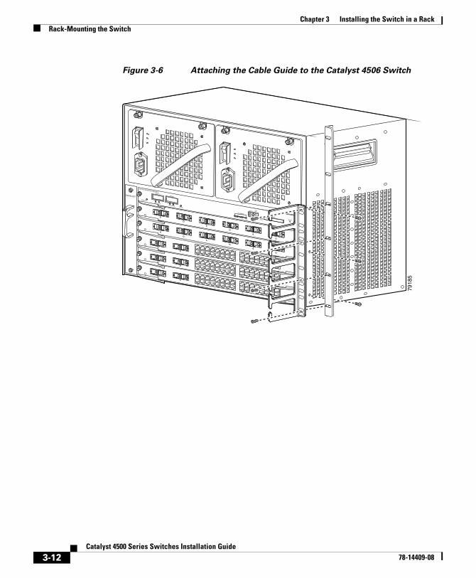
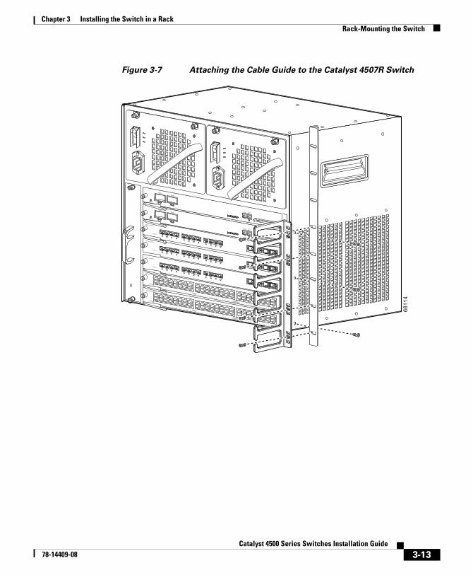
c. Attach the cable guide, if needed, using the M3 screws provided in the cable management kit. The cable guide attaches to the L bracket. Attach the cable guide to the right side of the switch to prevent the cables from obscuring module LEDs.
See Figure 3-5 for the Catalyst 4503 switch, Figure 3-6 for the Catalyst 4506 switch, Figure 3-7 for the Catalyst 4507R switch, or Figure 3-8 for the Catalyst 4510R switch.
4342
3
1
2
WS-X4448-GB-RJ45
STATUS
121110987654321
1413
1615
282726252423222120191817
3029
3231
444342414039383736353433
4645
4847
10/100BASE-TXETHERNET
MULTI-SPEEDGIGABIT ETHERNETSWITCHING MODULE
WS-X4448-GB-RJ45
STATUS
121110987654321
1413
1615
282726252423222120191817
3029
3231
444342414039383736353433
4645
4847
10/100BASE-TXETHERNET
MULTI-SPEEDGIGABIT ETHERNETSWITCHING MODULE
WS-X4448-GB-RJ45
STATUS
121110987654321
1413
1615
282726252423222120191817
3029
3231
444342414039383736353433
4645
4847
10/100BASE-TXETHERNET
MULTI-SPEEDGIGABIT ETHERNETSWITCHING MODULE
WS-X4448-GB-RJ45
STATUS
121110987654321
1413
1615
282726252423222120191817
3029
3231
444342414039383736353433
4645
4847
10/100BASE-TXETHERNET
MULTI-SPEEDGIGABIT ETHERNETSWITCHING MODULE
1
STATUS
WS-X4412-2GB-TX
23
45
67
89
1011
12
17
1
STATUS
WS-X4412-2GB-TX
23
45
67
89
1011
12
17
1
STATUS
WS-X4412-2GB-TX
23
45
67
89
1011
12
17
UPLINKUPLINK
CONSOLE 10/100BASE-TX
STATUS
UPLINKUPLINK
CONSOLE 10/100BASE-TX
STATUS
9493
8
3-10Catalyst 4500 Series Switches Installation Guide
78-14409-08
Chapter 3 Installing the Switch in a RackRack-Mounting the Switch
Figure 3-5 Attaching the Cable Guide to the Catalyst 4503 Switch
1
13
1
13
1
13
1
13
7918
4
4506UPLINK 1
UPLINK 2
ACTIVE
LINE ACTIVELINE ACTIVE
RESET
UTILIZATION
STATUS
4503
WS-X4515 SUPERVISOR ENGINE IV
1%
100%
CONSOLE
LINKEJECT
FLASH
10/100MGT
3-11Catalyst 4500 Series Switches Installation Guide
78-14409-08
Chapter 3 Installing the Switch in a RackRack-Mounting the Switch
Figure 3-6 Attaching the Cable Guide to the Catalyst 4506 Switch
1
13
1
13
1
13
1
13
1
13
1
13
7918
5
UPLINK 1
UPLINK 2
ACTIVE
LINE ACTIVELINE ACTIVE
RESET
UTILIZATION
STATUS
WS-X4515 SUPERVISOR ENGINE IV
1%
100%
CONSOLE
LINKEJECT
FLASH
10/100MGT
3-12Catalyst 4500 Series Switches Installation Guide
78-14409-08
Chapter 3 Installing the Switch in a RackRack-Mounting the Switch
Figure 3-7 Attaching the Cable Guide to the Catalyst 4507R Switch
6811
4
WS-X4448-GB-RJ45
STATUS
121110987654321
1413
1615
282726252423222120191817
3029
3231
444342414039383736353433
4645
4847
10/100BASE-TXETHERNET
MULTI-SPEEDGIGABIT ETHERNETSWITCHING MODULE
WS-X4448-GB-RJ45
STATUS
121110987654321
1413
1615
282726252423222120191817
3029
3231
444342414039383736353433
4645
4847
10/100BASE-TXETHERNET
MULTI-SPEEDGIGABIT ETHERNETSWITCHING MODULE
1
STATUS
WS-X4412-2GB-TX
23
45
67
89
1011
12
17
1
STATUS
WS-X4412-2GB-TX
23
45
67
89
1011
12
17
1
STATUS
WS-X4412-2GB-TX
23
45
67
89
1011
12
17
UPLINKUPLINK
CONSOLE 10/100BASE-TX
STATUS
UPLINKUPLINK
CONSOLE 10/100BASE-TX
STATUS
3-13Catalyst 4500 Series Switches Installation Guide
78-14409-08
Chapter 3 Installing the Switch in a RackRack-Mounting the Switch
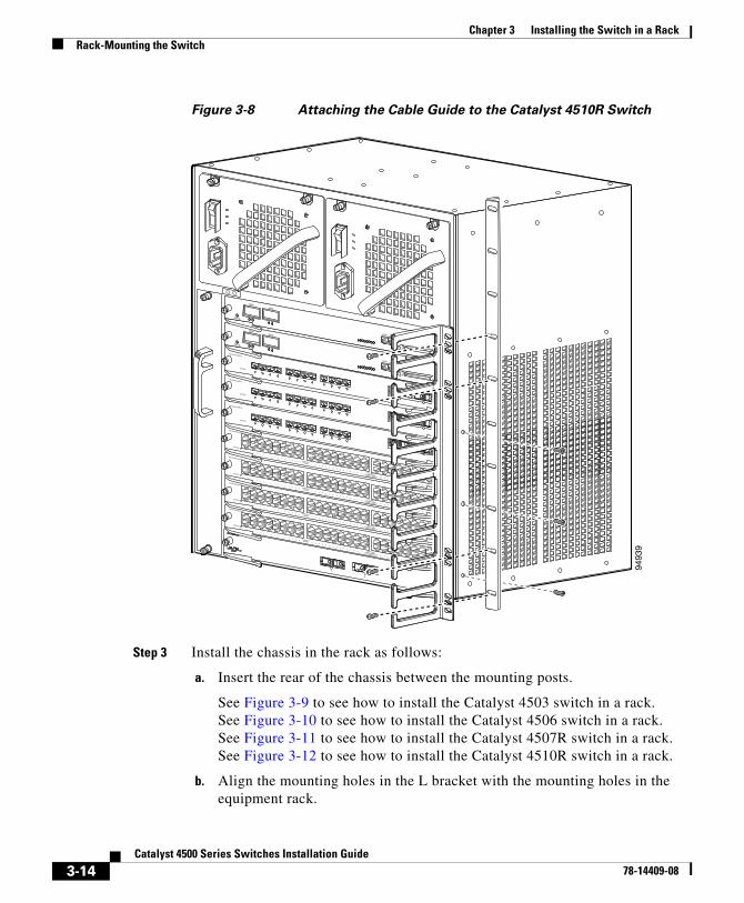
Figure 3-8 Attaching the Cable Guide to the Catalyst 4510R Switch
Step 3 Install the chassis in the rack as follows:
a. Insert the rear of the chassis between the mounting posts.
See Figure 3-9 to see how to install the Catalyst 4503 switch in a rack. See Figure 3-10 to see how to install the Catalyst 4506 switch in a rack. See Figure 3-11 to see how to install the Catalyst 4507R switch in a rack. See Figure 3-12 to see how to install the Catalyst 4510R switch in a rack.
b. Align the mounting holes in the L bracket with the mounting holes in the equipment rack.
4342
3
1
2
WS-X4448-GB-RJ45
STATUS
121110987654321
1413
1615
282726252423222120191817
3029
3231
444342414039383736353433
4645
4847
10/100BASE-TXETHERNET
MULTI-SPEEDGIGABIT ETHERNETSWITCHING MODULE
WS-X4448-GB-RJ45
STATUS
121110987654321
1413
1615
282726252423222120191817
3029
3231
444342414039383736353433
4645
4847
10/100BASE-TXETHERNET
MULTI-SPEEDGIGABIT ETHERNETSWITCHING MODULE
WS-X4448-GB-RJ45
STATUS
121110987654321
1413
1615
282726252423222120191817
3029
3231
444342414039383736353433
4645
4847
10/100BASE-TXETHERNET
MULTI-SPEEDGIGABIT ETHERNETSWITCHING MODULE
WS-X4448-GB-RJ45
STATUS
121110987654321
1413
1615
282726252423222120191817
3029
3231
444342414039383736353433
4645
4847
10/100BASE-TXETHERNET
MULTI-SPEEDGIGABIT ETHERNETSWITCHING MODULE
1
STATUS
WS-X4412-2GB-TX
23
45
67
89
1011
12
17
1
STATUS
WS-X4412-2GB-TX
23
45
67
89
1011
12
17
1
STATUS
WS-X4412-2GB-TX
23
45
67
89
1011
12
17
UPLINKUPLINK
CONSOLE 10/100BASE-TX
STATUS
UPLINKUPLINK
CONSOLE 10/100BASE-TX
STATUS
9493
9
3-14Catalyst 4500 Series Switches Installation Guide
78-14409-08
Chapter 3 Installing the Switch in a RackRack-Mounting the Switch
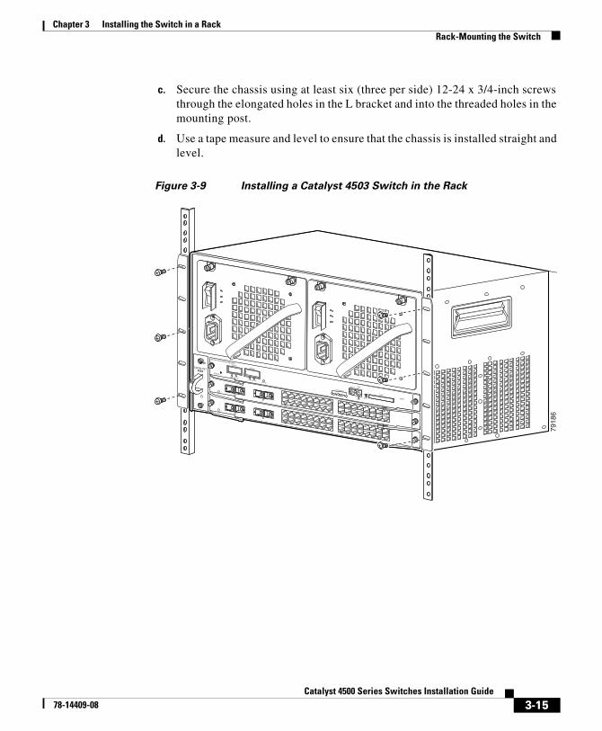
c. Secure the chassis using at least six (three per side) 12-24 x 3/4-inch screws through the elongated holes in the L bracket and into the threaded holes in the mounting post.
d. Use a tape measure and level to ensure that the chassis is installed straight and level.
Figure 3-9 Installing a Catalyst 4503 Switch in the Rack
1
13
1
13
1
13
1
13
7918
6
4506UPLINK 1
UPLINK 2
ACTIVE
LINE ACTIVELINE ACTIVE
RESET
UTILIZATION
STATUS
4503
WS-X4515 SUPERVISOR ENGINE IV
1%
100%
CONSOLE
LINKEJECT
FLASH
10/100MGT
3-15Catalyst 4500 Series Switches Installation Guide
78-14409-08
Chapter 3 Installing the Switch in a RackRack-Mounting the Switch
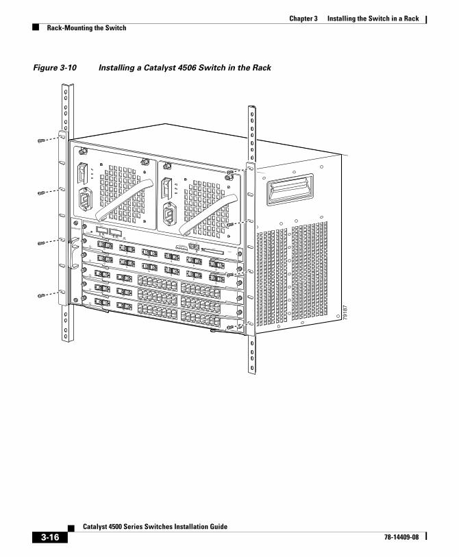
Figure 3-10 Installing a Catalyst 4506 Switch in the Rack
1
13
1
13
1
13
1
13
1
13
1
13
7918
7
UPLINK 1
UPLINK 2
ACTIVE
LINE ACTIVELINE ACTIVE
RESET
UTILIZATION
STATUS
WS-X4515 SUPERVISOR ENGINE IV
1%
100%
CONSOLE
LINKEJECT
FLASH
10/100MGT
3-16Catalyst 4500 Series Switches Installation Guide
78-14409-08
Chapter 3 Installing the Switch in a RackRack-Mounting the Switch
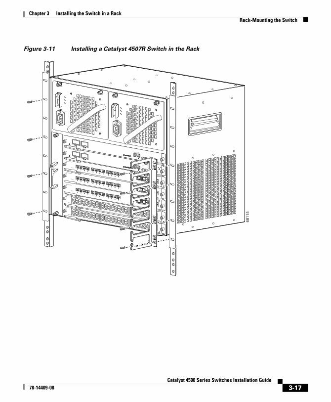
Figure 3-11 Installing a Catalyst 4507R Switch in the Rack
6811
5
WS-X4448-GB-RJ45
STATUS
121110987654321
1413
1615
282726252423222120191817
3029
3231
444342414039383736353433
4645
4847
10/100BASE-TXETHERNET
MULTI-SPEEDGIGABIT ETHERNETSWITCHING MODULE
WS-X4448-GB-RJ45
STATUS
121110987654321
1413
1615
282726252423222120191817
3029
3231
444342414039383736353433
4645
4847
10/100BASE-TXETHERNET
MULTI-SPEEDGIGABIT ETHERNETSWITCHING MODULE
1
STATUS
WS-X4412-2GB-TX
23
45
67
89
1011
12
17
1
STATUS
WS-X4412-2GB-TX
23
45
67
89
1011
12
17
1
STATUS
WS-X4412-2GB-TX
23
45
67
89
1011
12
17
UPLINKUPLINK
CONSOLE 10/100BASE-TX
STATUS
UPLINKUPLINK
CONSOLE 10/100BASE-TX
STATUS
3-17Catalyst 4500 Series Switches Installation Guide
78-14409-08
Chapter 3 Installing the Switch in a RackRack-Mounting the Switch
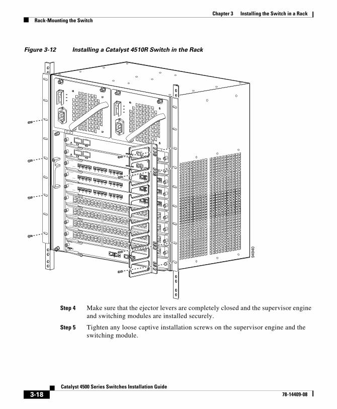
Figure 3-12 Installing a Catalyst 4510R Switch in the Rack
Step 4 Make sure that the ejector levers are completely closed and the supervisor engine and switching modules are installed securely.
Step 5 Tighten any loose captive installation screws on the supervisor engine and the switching module.
4342
3
1
2
WS-X4448-GB-RJ45
STATUS
121110987654321
1413
1615
282726252423222120191817
3029
3231
444342414039383736353433
4645
4847
10/100BASE-TXETHERNET
MULTI-SPEEDGIGABIT ETHERNETSWITCHING MODULE
WS-X4448-GB-RJ45
STATUS
121110987654321
1413
1615
282726252423222120191817
3029
3231
444342414039383736353433
4645
4847
10/100BASE-TXETHERNET
MULTI-SPEEDGIGABIT ETHERNETSWITCHING MODULE
WS-X4448-GB-RJ45
STATUS
121110987654321
1413
1615
282726252423222120191817
3029
3231
444342414039383736353433
4645
4847
10/100BASE-TXETHERNET
MULTI-SPEEDGIGABIT ETHERNETSWITCHING MODULE
WS-X4448-GB-RJ45
STATUS
121110987654321
1413
1615
282726252423222120191817
3029
3231
444342414039383736353433
4645
4847
10/100BASE-TXETHERNET
MULTI-SPEEDGIGABIT ETHERNETSWITCHING MODULE
1
STATUS
WS-X4412-2GB-TX
23
45
67
89
1011
12
17
1
STATUS
WS-X4412-2GB-TX
23
45
67
89
1011
12
17
1
STATUS
WS-X4412-2GB-TX
23
45
67
89
1011
12
17
UPLINKUPLINK
CONSOLE 10/100BASE-TX
STATUS
UPLINKUPLINK
CONSOLE 10/100BASE-TX
STATUS
9494
0
3-18Catalyst 4500 Series Switches Installation Guide
78-14409-08
Chapter 3 Installing the Switch in a RackSystem Ground Connection Guidelines
Step 6 Connect the switch to an appropriate ground. Refer to System Ground Connection Guidelines, page 3-19. The system must have a ground connection before power is supplied to the switch.
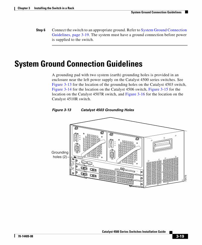
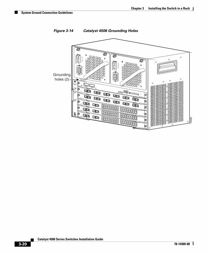
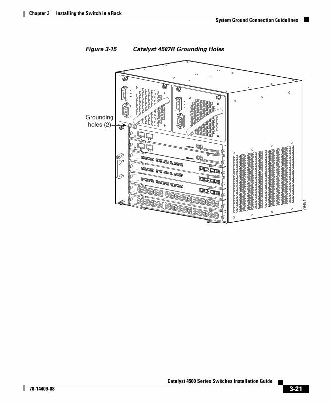
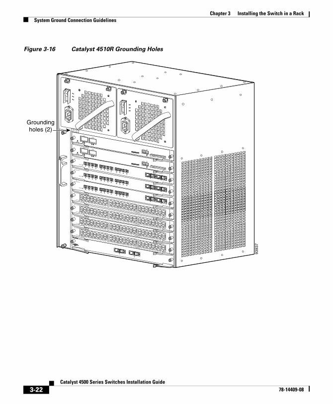
System Ground Connection GuidelinesA grounding pad with two system (earth) grounding holes is provided in an enclosure near the left power supply on the Catalyst 4500 series switches. See Figure 3-13 for the location of the grounding holes on the Catalyst 4503 switch, Figure 3-14 for the location on the Catalyst 4506 switch, Figure 3-15 for the location on the Catalyst 4507R switch, and Figure 3-16 for the location on the Catalyst 4510R switch.
Figure 3-13 Catalyst 4503 Grounding Holes
1
13
1
13
1
13
1
13
7947
9
4506UPLINK 1
UPLINK 2
ACTIVE
LINE ACTIVELINE ACTIVE
RESET
UTILIZATION
STATUS
4503
WS-X4515 SUPERVISOR ENGINE IV
1%
100%
CONSOLE
LINKEJECT
FLASH
10/100MGT
Groundingholes (2)
3-19Catalyst 4500 Series Switches Installation Guide
78-14409-08
Chapter 3 Installing the Switch in a RackSystem Ground Connection Guidelines
Figure 3-14 Catalyst 4506 Grounding Holes
1
13
1
13
1
13
1
13
1
13
1
13
7948
0
4506
UPLINK 1
UPLINK 2
ACTIVE
LINE ACTIVELINE ACTIVE
RESET
UTILIZATION
STATUS
WS-X4515 SUPERVISOR ENGINE IV
1%
100%
CONSOLE
LINKEJECT
FLASH
10/100MGT
Groundingholes (2)
3-20Catalyst 4500 Series Switches Installation Guide
78-14409-08
Chapter 3 Installing the Switch in a RackSystem Ground Connection Guidelines
Figure 3-15 Catalyst 4507R Grounding Holes
7948
1
WS-X4448-GB-RJ45
STATUS
121110987654321
1413
1615
282726252423222120191817
3029
3231
444342414039383736353433
4645
4847
10/100BASE-TXETHERNET
MULTI-SPEEDGIGABIT ETHERNETSWITCHING MODULE
WS-X4448-GB-RJ45
STATUS
121110987654321
1413
1615
282726252423222120191817
3029
3231
444342414039383736353433
4645
4847
10/100BASE-TXETHERNET
MULTI-SPEEDGIGABIT ETHERNETSWITCHING MODULE
1
STATUS
WS-X4412-2GB-TX
23
45
67
89
1011
12
17
1
STATUS
WS-X4412-2GB-TX
23
45
67
89
1011
12
17
1
STATUS
WS-X4412-2GB-TX
23
45
67
89
1011
12
17
UPLINKUPLINK
CONSOLE 10/100BASE-TX
STATUS
UPLINKUPLINK
CONSOLE 10/100BASE-TX
STATUS
Groundingholes (2)
3-21Catalyst 4500 Series Switches Installation Guide
78-14409-08
Chapter 3 Installing the Switch in a RackSystem Ground Connection Guidelines
Figure 3-16 Catalyst 4510R Grounding Holes
9393
7
WS-X4448-GB-RJ45
STATUS
121110987654321
1413
1615
282726252423222120191817
3029
3231
444342414039383736353433
4645
4847
10/100BASE-TXETHERNET
MULTI-SPEEDGIGABIT ETHERNETSWITCHING MODULE
WS-X4448-GB-RJ45
STATUS
121110987654321
1413
1615
282726252423222120191817
3029
3231
444342414039383736353433
4645
4847
10/100BASE-TXETHERNET
MULTI-SPEEDGIGABIT ETHERNETSWITCHING MODULE
WS-X4448-GB-RJ45
STATUS
121110987654321
1413
1615
282726252423222120191817
3029
3231
444342414039383736353433
4645
4847
10/100BASE-TXETHERNET
MULTI-SPEEDGIGABIT ETHERNETSWITCHING MODULE
WS-X4448-GB-RJ45
STATUS
121110987654321
1413
1615
282726252423222120191817
3029
3231
444342414039383736353433
4645
4847
10/100BASE-TXETHERNET
MULTI-SPEEDGIGABIT ETHERNETSWITCHING MODULE
1
STATUS
WS-X4412-2GB-TX
23
45
67
89
1011
12
17
1
STATUS
WS-X4412-2GB-TX
23
45
67
89
1011
12
17
1
STATUS
WS-X4412-2GB-TX
23
45
67
89
1011
12
17
UPLINKUPLINK
CONSOLE 10/100BASE-TX
STATUS
UPLINKUPLINK
CONSOLE 10/100BASE-TX
STATUS
Groundingholes (2)
1
2
3-22Catalyst 4500 Series Switches Installation Guide
78-14409-08
Chapter 3 Installing the Switch in a RackSystem Ground Connection Guidelines
Parts and Required Tools
Note Some parts and required tools described in this section are not available from Cisco Systems. The grounding lug and associated screws are included with the accessory kit.
To make an adequate grounding connection, you will need the following parts and tools:
• Grounding lug—The grounding lug has two #10 AWG holes spaced 0.63 in center to center. A Panduit LCDX6-10A-L or Pencom EL1033 lug may be used if the lug from the accessory kit has been misplaced.
• Two M4 (metric) hex-head screws.
• One grounding wire (6 AWG recommended)—The length of the grounding wires depends on the location of your switch within the site and its proximity to proper grounding facilities.
• Number 2 Phillips screwdriver.
• Crimping tool—This tool must be large enough to accommodate the girth of the grounding lug when you crimp the grounding cable into the lug.
• Wire-stripping tool.
3-23Catalyst 4500 Series Switches Installation Guide
78-14409-08
Chapter 3 Installing the Switch in a RackSystem Ground Connection Guidelines
Connecting System Ground and PowerThis section describes how to connect the Catalyst 4500 series switches to earth ground. The system ground connection is required if FXS modules are installed or if this equipment is installed in a US or European Central Office.You must complete this procedure before connecting system power or turning on your switch.
To attach the grounding lug and cable to the grounding pad on your Catalyst 4500 series switch, perform the following steps:
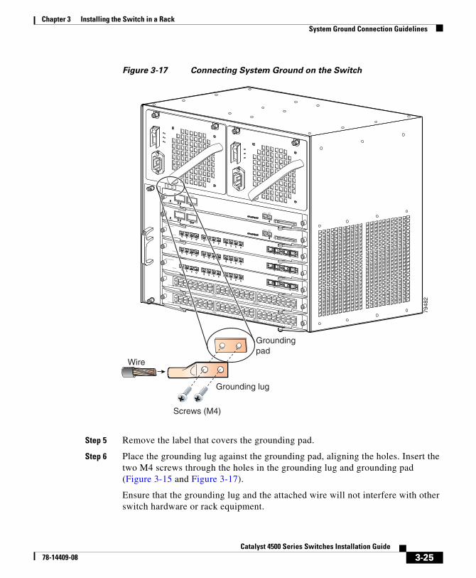
Step 1 Using a wire-stripping tool, remove approximately 0.75 inches (19 mm) of the covering from the end of the grounding wire.
Step 2 Insert the stripped end of the grounding wire into the open end of the grounding lug (Figure 3-17).
Step 3 Using a crimping tool, secure the grounding wire in place in the grounding lug.
Step 4 Locate the grounding pad on the switch.
See Figure 3-13 for the location of the grounding holes on the Catalyst 4503 switch, Figure 3-14 for the location on the Catalyst 4506 switch, Figure 3-15 for the location on the Catalyst 4507R switch, and Figure 3-16 for the location on the Catalyst 4510R switch.
3-24Catalyst 4500 Series Switches Installation Guide
78-14409-08
Chapter 3 Installing the Switch in a RackSystem Ground Connection Guidelines
Figure 3-17 Connecting System Ground on the Switch
Step 5 Remove the label that covers the grounding pad.
Step 6 Place the grounding lug against the grounding pad, aligning the holes. Insert the two M4 screws through the holes in the grounding lug and grounding pad (Figure 3-15 and Figure 3-17).
Ensure that the grounding lug and the attached wire will not interfere with other switch hardware or rack equipment.
7948
2
WS-X4448-GB-RJ45
STATUS
121110987654321
1413
1615
282726252423222120191817
3029
3231
444342414039383736353433
4645
4847
10/100BASE-TXETHERNET
MULTI-SPEEDGIGABIT ETHERNETSWITCHING MODULE
WS-X4448-GB-RJ45
STATUS
121110987654321
1413
1615
282726252423222120191817
3029
3231
444342414039383736353433
4645
4847
10/100BASE-TXETHERNET
MULTI-SPEEDGIGABIT ETHERNETSWITCHING MODULE
1
STATUS
WS-X4412-2GB-TX
23
45
67
89
1011
12
17
1
STATUS
WS-X4412-2GB-TX
23
45
67
89
1011
12
17
1
STATUS
WS-X4412-2GB-TX
23
45
67
89
1011
12
17
UPLINKUPLINK
CONSOLE 10/100BASE-TX
STATUS
UPLINKUPLINK
CONSOLE 10/100BASE-TX
STATUS
Groundingpad
Grounding lug
Wire
Screws (M4)
3-25Catalyst 4500 Series Switches Installation Guide
78-14409-08
Chapter 3 Installing the Switch in a RackSystem Ground Connection Guidelines
Step 7 Tighten the screws to secure the grounding lug to the grounding pad.
Step 8 Repeat steps 1 through 3 to prepare the other end of the grounding wire and connect it to an appropriate grounding point at your site to ensure adequate earth ground for the switch.
Step 9 Connect the power supply cords.
The switch comes on when the cords are connected and the power supply on/off switch is on.
Note This equipment is suitable for connection to intra-building wiring only.
Note If you are using a DC power supply, the DC return connection to this system should remain isolated from the system frame and chassis (DC-I).
This completes the installation of the Catalyst 4500 series switches.
At this point you should use a RJ-45-to-RJ-45 rollover cable (not supplied) to connect the console port to a PC that runs terminal emulation software. Configure your terminal emulation program for 9600 baud, 8 data bits, no parity, and 1 stop bit. With this console connection, you can configure the switch as discussed in the software configuration guide appropriate for your switch’s software release, and monitor the software as the switch goes through its startup routine.
Note If meaningless characters (garbage) are seen during or after the switch bootup, verify that you have the correct baud rate setup on your terminal emulation software. If the situation persists, you need to disconnect the RJ-45-to-RJ-45 rollover cable and replace it with a shielded cable (Cisco p/n 72-1499-01). The shielded cable eliminates the EMI noise causing the meaningless characters.
The pinout for the console port is detailed in the module installation guide at:
http://www.cisco.com/en/US/docs/switches/lan/catalyst4500/hardware/configuration/notes/OL_25315.html
3-26Catalyst 4500 Series Switches Installation Guide
78-14409-08