Embed Size (px)
Citation preview

Installing and Configuring the Avaya S8400 Media ServerRelease 3.1
03-300678Release 3.1
February 2006Issue 1

© 2006 Avaya Inc.All Rights Reserved.
NoticeWhile reasonable efforts were made to ensure that the information in this document was complete and accurate at the time of printing, Avaya Inc. can assume no liability for any errors. Changes and corrections to the information in this document may be incorporated in future releases.For full legal page information, please see the complete document, Avaya Legal Page for Hardware Documentation, document number03-600759.To locate this document on our Web site, simply go to http://www.avaya.com/support and search for the document number in the search box.
Documentation disclaimerAvaya Inc. is not responsible for any modifications, additions, or deletions to the original published version of this documentation unless such modifications, additions, or deletions were performed by Avaya. Customer and/or End User agree to indemnify and hold harmless Avaya, Avaya's agents, servants and employees against all claims, lawsuits, demands and judgments arising out of, or in connection with, subsequent modifications, additions or deletions to this documentation to the extent made by the Customer or End User.
Link disclaimerAvaya Inc. is not responsible for the contents or reliability of any linked Web sites referenced elsewhere within this documentation, and Avaya does not necessarily endorse the products, services, or information described or offered within them. We cannot guarantee that these links will work all of the time and we have no control over the availability of the linked pages.
WarrantyAvaya Inc. provides a limited warranty on this product. Refer to your sales agreement to establish the terms of the limited warranty. In addition, Avaya’s standard warranty language, as well as information regarding support for this product, while under warranty, is available through the following Web site:http://www.avaya.com/support.
CopyrightExcept where expressly stated otherwise, the Product is protected by copyright and other laws respecting proprietary rights. Unauthorized reproduction, transfer, and or use can be a criminal, as well as a civil, offense under the applicable law.
Avaya supportAvaya provides a telephone number for you to use to report problems or to ask questions about your product. The support telephone number is 1-800-242-2121 in the United States. For additional support telephone numbers, see the Avaya Web site: http://www.avaya.com/support.

Installing and Configuring the Avaya S8400 Media Server February 2006 3
Chapter 1: Introduction . . . . . . . . . . . . . . . . . . . . . . . . . . . . . . . . . . 7Audience . . . . . . . . . . . . . . . . . . . . . . . . . . . . . . . . . . . . . . . . 7How to use this documentation . . . . . . . . . . . . . . . . . . . . . . . . . . . 8Pre-installation: before going on site . . . . . . . . . . . . . . . . . . . . . . . . 9
Documentation. . . . . . . . . . . . . . . . . . . . . . . . . . . . . . . . . . . 9Verifying site readiness . . . . . . . . . . . . . . . . . . . . . . . . . . . . . . 9Laptop preparation, software, and system information. . . . . . . . . . . . . 10Copying files to the laptop . . . . . . . . . . . . . . . . . . . . . . . . . . . . 10About ASG and the unique on-site password . . . . . . . . . . . . . . . . . . 11Obtaining license and Avaya authentication files . . . . . . . . . . . . . . . . 11
Pre-installation: at the site . . . . . . . . . . . . . . . . . . . . . . . . . . . . . . 13Equipment specifications . . . . . . . . . . . . . . . . . . . . . . . . . . . . . . . 13About media server port connections . . . . . . . . . . . . . . . . . . . . . . . . 14
Ethernet ports . . . . . . . . . . . . . . . . . . . . . . . . . . . . . . . . . . . 14Media server cable adapter . . . . . . . . . . . . . . . . . . . . . . . . . . . . 15Ethernet connectivity with the TN8412AP circuit pack . . . . . . . . . . . . . 16Services access port . . . . . . . . . . . . . . . . . . . . . . . . . . . . . . . 19
About Modem connections . . . . . . . . . . . . . . . . . . . . . . . . . . . . . 20About Media Gateways . . . . . . . . . . . . . . . . . . . . . . . . . . . . . . . . 20About Processor Ethernet . . . . . . . . . . . . . . . . . . . . . . . . . . . . . . 21About SSH . . . . . . . . . . . . . . . . . . . . . . . . . . . . . . . . . . . . . . . 22High level overview of installation process . . . . . . . . . . . . . . . . . . . . . 23
Installing and cabling the media gateways . . . . . . . . . . . . . . . . . . . 23Installing Avaya Communication Manager. . . . . . . . . . . . . . . . . . . . 23Configuring the MPC . . . . . . . . . . . . . . . . . . . . . . . . . . . . . . . 23Configuring the media server . . . . . . . . . . . . . . . . . . . . . . . . . . . 23Translating the SIPI . . . . . . . . . . . . . . . . . . . . . . . . . . . . . . . . 24Completing the installation administration . . . . . . . . . . . . . . . . . . . 24Testing the finished installation . . . . . . . . . . . . . . . . . . . . . . . . . 24
Chapter 2: SNMP Configuration . . . . . . . . . . . . . . . . . . . . . . . . . . . . . 25Configuration of the SNMP modules in the UPS . . . . . . . . . . . . . . . . . . 25
Default UPS IP addresses . . . . . . . . . . . . . . . . . . . . . . . . . . . . . 26Preparing to configure the SNMP module . . . . . . . . . . . . . . . . . . . . 26Administering the SNMP module . . . . . . . . . . . . . . . . . . . . . . . . . 27Setting selected traps (alarming) . . . . . . . . . . . . . . . . . . . . . . . . 28
Contents

Contents
4 Installing and Configuring the Avaya S8400 Media Server February 2006
Chapter 3: Communication Manager Installation . . . . . . . . . . . . . . . . . . . . 29Clearing the ARP cache on the laptop . . . . . . . . . . . . . . . . . . . . . . . . 29Connecting the CD/DVD drive to the media server . . . . . . . . . . . . . . . . . 30Powering up the media server . . . . . . . . . . . . . . . . . . . . . . . . . . . . 30Accessing the media server . . . . . . . . . . . . . . . . . . . . . . . . . . . . . 30Configuring Telnet for Windows 2000/XP . . . . . . . . . . . . . . . . . . . . . . 31Installing Avaya Communication Manager . . . . . . . . . . . . . . . . . . . . . 32Installing IA 770 INTUITY AUDIX Messaging . . . . . . . . . . . . . . . . . . . . 33
Chapter 4: Media server configuration . . . . . . . . . . . . . . . . . . . . . . . . . . 35Opening the Maintenance Web Interface. . . . . . . . . . . . . . . . . . . . . . . 35Copying files to the media server . . . . . . . . . . . . . . . . . . . . . . . . . . 36Enabling Network Time Servers . . . . . . . . . . . . . . . . . . . . . . . . . . . 37Using the Installation Wizard . . . . . . . . . . . . . . . . . . . . . . . . . . . . . 38Verifying MPC IP information . . . . . . . . . . . . . . . . . . . . . . . . . . . . . 39Installing MPC firmware . . . . . . . . . . . . . . . . . . . . . . . . . . . . . . . 39Verifying media server connection to the customer’s LAN (if provided) . . . . . 40Enabling firewall settings . . . . . . . . . . . . . . . . . . . . . . . . . . . . . . . 40Configuring the modem . . . . . . . . . . . . . . . . . . . . . . . . . . . . . . . 41
Chapter 5: IP interface translations . . . . . . . . . . . . . . . . . . . . . . . . . . 43Starting SAT terminal emulation . . . . . . . . . . . . . . . . . . . . . . . . . . . 44Inputting initial system translations . . . . . . . . . . . . . . . . . . . . . . . . . 44Adding media gateways . . . . . . . . . . . . . . . . . . . . . . . . . . . . . . . 44Enabling SIPI . . . . . . . . . . . . . . . . . . . . . . . . . . . . . . . . . . . . . 45Adding the SIPI to the system . . . . . . . . . . . . . . . . . . . . . . . . . . . . 46Setting alarm activation level . . . . . . . . . . . . . . . . . . . . . . . . . . . . 47Saving translations . . . . . . . . . . . . . . . . . . . . . . . . . . . . . . . . . . 47
Chapter 6: IP interface configuration. . . . . . . . . . . . . . . . . . . . . . . . . . . 49SIPI address configuration . . . . . . . . . . . . . . . . . . . . . . . . . . . . . . 49
Programming the SIPI for static addressing . . . . . . . . . . . . . . . . . 50Setting the VLAN and diffserv parameters. . . . . . . . . . . . . . . . . . . . . . 52Resetting the SIPI . . . . . . . . . . . . . . . . . . . . . . . . . . . . . . . . . . . 53Verifying connectivity to media server . . . . . . . . . . . . . . . . . . . . . . . 54Verifying that SIPI is translated . . . . . . . . . . . . . . . . . . . . . . . . . . . 54

Contents
Installing and Configuring the Avaya S8400 Media Server February 2006 5
Upgrading the SIPI firmware version (if necessary) . . . . . . . . . . . . . . . . 54Enabling control of SIPI . . . . . . . . . . . . . . . . . . . . . . . . . . . . . . . 55Verifying license status . . . . . . . . . . . . . . . . . . . . . . . . . . . . . . . . 55
Chapter 7: Post-installation administration . . . . . . . . . . . . . . . . . . . . . . . 57Verifying translations . . . . . . . . . . . . . . . . . . . . . . . . . . . . . . . . . 57Setting daylight savings time rules . . . . . . . . . . . . . . . . . . . . . . . . . 58Setting locations (if necessary) . . . . . . . . . . . . . . . . . . . . . . . . . . . 59Verifying date and time . . . . . . . . . . . . . . . . . . . . . . . . . . . . . . . . 60Clearing and resolving alarms . . . . . . . . . . . . . . . . . . . . . . . . . . . . 60Backing up files to the compact flash media . . . . . . . . . . . . . . . . . . . . 61Enabling alarms to INADS via modem . . . . . . . . . . . . . . . . . . . . . . . . 61Enabling alarms to INADS via SNMP . . . . . . . . . . . . . . . . . . . . . . . . 62Before leaving the site. . . . . . . . . . . . . . . . . . . . . . . . . . . . . . . . . 62
Chapter 8: Installation verification . . . . . . . . . . . . . . . . . . . . . . . . . . . . 63Testing the SIPI circuit pack . . . . . . . . . . . . . . . . . . . . . . . . . . . . . 64Testing the license file . . . . . . . . . . . . . . . . . . . . . . . . . . . . . . . . 64TN8400AP Media Server LEDs . . . . . . . . . . . . . . . . . . . . . . . . . . . . 65
Faceplate interfaces . . . . . . . . . . . . . . . . . . . . . . . . . . . . . . . 66LED descriptions . . . . . . . . . . . . . . . . . . . . . . . . . . . . . . . . . 67
UPS LEDs . . . . . . . . . . . . . . . . . . . . . . . . . . . . . . . . . . . . . . . 68TN8412AP SIPI LEDs . . . . . . . . . . . . . . . . . . . . . . . . . . . . . . . . 69
Appendix A: Media server access . . . . . . . . . . . . . . . . . . . . . . . . . . . . 73Accessing the server’s command line interface with SSH . . . . . . . . . . . . . 73Connecting to the media server directly . . . . . . . . . . . . . . . . . . . . . . 75Connecting to the media server remotely over the network . . . . . . . . . . . . 76Connecting to the media server remotely over a modem . . . . . . . . . . . . . 77Accessing the Maintenance Web Interface . . . . . . . . . . . . . . . . . . . . . 78Using the SAT command line prompt . . . . . . . . . . . . . . . . . . . . . . . . 78Logins for Avaya technicians and Business Partners . . . . . . . . . . . . . . . 79Configuring the network for Windows 2000/XP . . . . . . . . . . . . . . . . . . . 80Setting browser options for Internet Explorer 6.0. . . . . . . . . . . . . . . . . . 81

Contents
6 Installing and Configuring the Avaya S8400 Media Server February 2006
Appendix B: Installation troubleshooting . . . . . . . . . . . . . . . . . . . . . . . . 83Troubleshooting media server hardware installation . . . . . . . . . . . . . . . . 83Troubleshooting configuring the media server hardware . . . . . . . . . . . . . 84Troubleshooting the installation of license files and Avaya authentication files . 86
Index . . . . . . . . . . . . . . . . . . . . . . . . . . . . . . . . . . . . . . . . 87
Installing and Configuring the Avaya S8400 Media Server February 2006 7
Chapter 1: Introduction
To configure the media server, use the Avaya Installation Wizard. To configure gateways and other hardware components, use two administration interfaces:
● Maintenance Web Interface
● Command line interface, directly through, secure shell (SSH), telnet, or a terminal emulation program such as Avaya Native Configuration Manager.
You are not required to install the media server before the port networks (media gateways); however, the license file allows only 30 minutes to "see" the administered and connected IP Interface (SIPI) circuit packs.
The following information is included in this installation procedure:
● Pre-installation: before going on site on page 9
● Configuration of the SNMP modules in the UPS on page 25
● Media server configuration on page 35
● IP interface translations on page 43
● IP interface configuration on page 49
● Post-installation administration on page 57
● Installation verification on page 63
● Media server access on page 73
● Installation troubleshooting on page 83
AudienceThis documentation is for the following people tasked with installing and configuring the media server components:
● Trained field installation and maintenance personnel
● Technical support personnel
● Authorized Business Partners

Chapter 1: Introduction
8 Installing and Configuring the Avaya S8400 Media Server February 2006
How to use this documentation Use this documentation as a guide to install and configure Avaya media servers. For information about a particular task, use the index or table of contents to locate the page number where the information is described.
For an overview of the installation process, see High level overview of installation process on page 23.
Read Pre-installation: before going on site on page 9 first. This section lists the tasks that must be completed before going to the installation site. Next, read Pre-installation: at the site on page 13. This section lists the tasks that must be completed on site before beginning the installation procedures.
Technical specifications for the hardware are described in Equipment specifications on page 13.
For the physical installation and cabling of the hardware, see the Quick Start for Hardware Installation: Avaya S8400 Media Server in an Avaya G650 Media Gateway (03-300705). Use the remaining sections of this document in the sequence they are presented. If certain components are not to be installed, skip the procedures for those components. You install and configure the media server components using information in the following sections:
● Configuration of the SNMP modules in the UPS on page 25
● Media server configuration on page 35
● IP interface translations on page 43
Next, install the port networks and media gateways, using sections in the following documents:
● Installing the Avaya G650 Media Gateway (03-300144)
● Installation and Configuration for the Avaya G150 Media Gateway (03-300395)
● Quick Start for Hardware Installation: Avaya G350 Media Gateway (03-300148)
● Installation of the Avaya G350 Media Gateway (555-245-104)
● Quick Start for Hardware Installation: Avaya S8300 Media Server and Avaya G700 Media Gateway (555-233-150)
● Installation and Upgrades for the Avaya G700 Media Gateway and Avaya S8300 Media Server (555-234-100)
Program the IP interface using Chapter 6: IP interface configuration.
Complete the installation using information in the following sections:
● Post-installation administration on page 57
● Installation verification on page 63
● Media server access on page 73
If problems occur during the installation, use Installation troubleshooting on page 83 to try to resolve them.

Pre-installation: before going on site
Installing and Configuring the Avaya S8400 Media Server February 2006 9
Pre-installation: before going on siteThis section describes the steps you need to take to before going to the installation site.
DocumentationAvaya recommends that you have the following documents on hand for the installation. These are included on the Documentation for Avaya Communication Manager, Media Gateways and Servers CD (03-300151).
● Quick Start for Hardware Installation: Avaya S8400 Media Server in an Avaya G650 Media Gateway (03-300705) — a quick reference guide providing physical installation and connection information.
● Completed Electronic Preinstallation Worksheet — An Excel spreadsheet providing the customer’s network information needed to use the Avaya Installation Wizard to configure the control network components. Get from the Avaya project manager, Avaya software technician, or customer network administrator. See the Avaya Installation Wizard Web site (http://support.avaya.com/avayaiw) for the blank form.
● Job Aid: Approved Grounds (555-245-772) — provides a description of all approved grounds.
Verifying site readinessBefore going on site, make sure the customer has:
● adequate power
● 19-in. (48-cm) 4-post data racks securely installed to EIA-310D (or equivalent) standards and grounded
● a local area network set up and running
● a network administrator available the day of the installation
If you are staging the installation at a location other than the customer’s site, verify that you have all the equipment by comparing the list of items ordered against the items in the boxes. Your project manager can supply you with an inventory list. Do not rely solely on the packing slips inside the boxes.
Chapter 1: Introduction
10 Installing and Configuring the Avaya S8400 Media Server February 2006
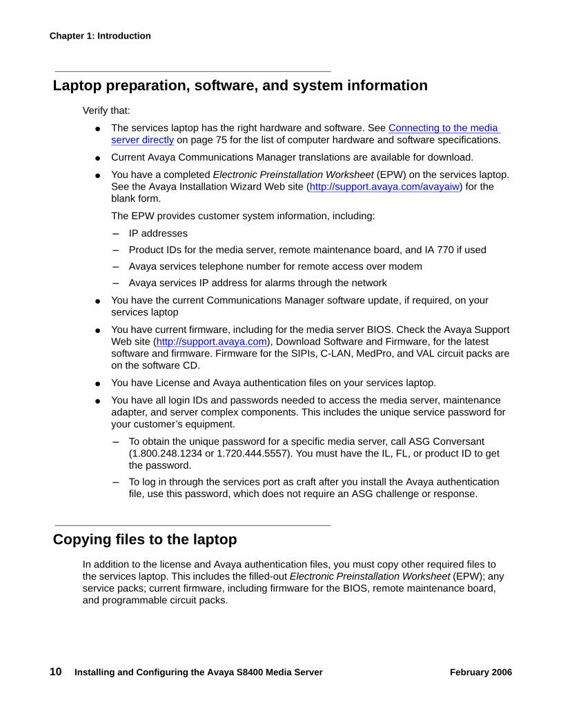
Laptop preparation, software, and system informationVerify that:
● The services laptop has the right hardware and software. See Connecting to the media server directly on page 75 for the list of computer hardware and software specifications.
● Current Avaya Communications Manager translations are available for download.
● You have a completed Electronic Preinstallation Worksheet (EPW) on the services laptop. See the Avaya Installation Wizard Web site (http://support.avaya.com/avayaiw) for the blank form.
The EPW provides customer system information, including:
- IP addresses- Product IDs for the media server, remote maintenance board, and IA 770 if used- Avaya services telephone number for remote access over modem- Avaya services IP address for alarms through the network
● You have the current Communications Manager software update, if required, on your services laptop
● You have current firmware, including for the media server BIOS. Check the Avaya Support Web site (http://support.avaya.com), Download Software and Firmware, for the latest software and firmware. Firmware for the SIPIs, C-LAN, MedPro, and VAL circuit packs are on the software CD.
● You have License and Avaya authentication files on your services laptop.
● You have all login IDs and passwords needed to access the media server, maintenance adapter, and server complex components. This includes the unique service password for your customer’s equipment.
- To obtain the unique password for a specific media server, call ASG Conversant (1.800.248.1234 or 1.720.444.5557). You must have the IL, FL, or product ID to get the password.
- To log in through the services port as craft after you install the Avaya authentication file, use this password, which does not require an ASG challenge or response.
Copying files to the laptop In addition to the license and Avaya authentication files, you must copy other required files to the services laptop. This includes the filled-out Electronic Preinstallation Worksheet (EPW); any service packs; current firmware, including firmware for the BIOS, remote maintenance board, and programmable circuit packs.

Pre-installation: before going on site
Installing and Configuring the Avaya S8400 Media Server February 2006 11
To get a filled-out EPW, go to the project manager or customer. To get a blank EPW, go to the Avaya Installation Wizard Web site (http://support.avaya.com/avayaiw). Have the customer fill it out.
To get the service pack, go to the Avaya Support Web site (http://avaya.com/support) and select Software & Firmware Downloads to identify and copy the required service pack.
To get the latest firmware for the BIOS, remote maintenance board, and programmable circuit packs, go to the Avaya Support Web site at http://avaya.com/support and select Software & Firmware Downloads to identify and copy the latest firmware.
To get instructions on installing firmware, go to:
ftp://ftp.avaya.com/incoming/Up1cku9/tsoweb/firmware/TNpackFirmwareDownloadInstructions.pdf
About ASG and the unique on-site passwordAfter installing the Avaya authentication files, Access Security Gateway (ASG) protects Avaya services logins to the media server. The ASG challenge/response protocol confirms the validity of each user, reducing the opportunity for unauthorized access.
If you use the craft password that is unique to the server of the customer and access the media server on site, you can use this password the next time you log in as craft. You do not need an ASG challenge/response to log in this way. Every other means of craft access still requires an ASG challenge/response.
Obtaining license and Avaya authentication filesUse Remote Feature Activation (RFA) to obtain the Communication Manager license and Avaya authentication files. RFA is a Web-based application, available to Avaya employees and authorized BusinessPartners. WIth RFA, you can create and deploy license files for all Communication Manager product platforms. For more information about RFA and how to generate license and Avaya authentication files, see the RFA Information page at http://rfa.avaya.com.
Note:Note: To access the RFA application, you must complete the RFA online training and
have received access authorization.
To generate a license file, you need the following information:
● Your personal Single Sign-On (SSO) for the RFA Web site authentication login
● SAP order number
● Required customer information
Chapter 1: Introduction
12 Installing and Configuring the Avaya S8400 Media Server February 2006
● For a new license, the serial number of one TN2312BP Internet Protocol Server Interface (IPSI) or TN8412AP System Internet Protocol Interface (SIPI) circuit pack designated the reference IP interface.
● For an updated license, the RFA system ID (SID) for the existing media server, which is necessary to locate the existing license
● Internet access to the RFA Web page with Internet Explorer 5.0 or higher
Before arriving on site, download the license and Avaya authentication files to the services laptop. The license and Avaya authentication files are installed during the installation process.
Once the Avaya authentication files are installed, a challenge/response system called Access Security Gateway (ASG) protects Avaya services logins to the media server. The ASG challenge/response protocol confirms the validity of each user, reducing the opportunity for unauthorized access.
When finished installing the Avaya authentication file, Avaya Communication Manager has a password for the craft login. This password is unique to the server of the customer. You can use the password the next time you log in as craft, provided you access the media server through the services port. You do not need an ASG challenge/response to log in this way, even though every other means of craft access still requires an ASG challenge/response. RFA records the revised password. ASG Conversant provides this password at 1-800-248-1234 or 1-720-444-5557.

Pre-installation: at the site
Installing and Configuring the Avaya S8400 Media Server February 2006 13
Pre-installation: at the siteBefore beginning the installation, verify that you have all the equipment on site by comparing the list of items ordered against the items in the boxes. Your project manager can supply you with an inventory list. Do not rely solely on the packing slips inside the boxes.
The pre-installation team should have done the following tasks. If they were not all done, do not continue with the installation.
● Verify that the open, customer-supplied, EIA-310D (or equivalent) standard 19-in. (48-cm) 4-post equipment rack(s) is(are) properly installed and solidly secured. Make sure that the screws that come with the racks are there. If using a rack cabinet, make sure it has adequate ventilation.
● Verify that the rail kit to support the media server is available for installation.
● Verify that the rail kit, required to support the very heavy UPS, is installed on the rack or available for installation. For information on installing the rails, see the documentation that comes with the rail kit.
● Verify that the equipment rack(s) is(are) grounded per local code. See Job Aid: Approved Grounds (555-245-772).
● Verify that the customer provides AC power to the rack from a nonswitched outlet.
● Verify that cabling between the TN8400AP and the TN8412AP (SIPI) circuit packs is in place.
Equipment specificationsThe S8400 Media Server control network components consist of a G650 Media Gateway with a TN8400AP circuit pack installed in slot 2, a TN8412AP (SIPI) installed in slot1, and one UPS. See Table 1: Control network components specifications.
Table 1: Control network components specifications
Component DimensionsEnglish (in.)
Metric (cm) U (height) Weight (lb/kg)
Media Gateway:G650 14h x 17.5w x 22d 30h x 56w x 48d 8 39/18
UPS:700 VA1500 VA
3.5h x 17w x 19d3.5h x 17w x 24d
9h x 43w x 48d9h x 43w x 61d
22
34/1550/23
Chapter 1: Introduction
14 Installing and Configuring the Avaya S8400 Media Server February 2006
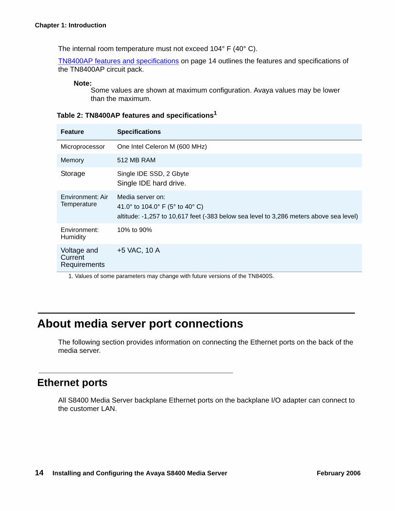
The internal room temperature must not exceed 104° F (40° C).
TN8400AP features and specifications on page 14 outlines the features and specifications of the TN8400AP circuit pack.
Note:Note: Some values are shown at maximum configuration. Avaya values may be lower
than the maximum.
About media server port connections The following section provides information on connecting the Ethernet ports on the back of the media server.
Ethernet portsAll S8400 Media Server backplane Ethernet ports on the backplane I/O adapter can connect to the customer LAN.
Table 2: TN8400AP features and specifications1
1. Values of some parameters may change with future versions of the TN8400S.
Feature Specifications
Microprocessor One Intel Celeron M (600 MHz)
Memory 512 MB RAM
Storage Single IDE SSD, 2 GbyteSingle IDE hard drive.
Environment: Air Temperature
Media server on:41.0° to 104.0° F (5° to 40° C)altitude: -1,257 to 10,617 feet (-383 below sea level to 3,286 meters above sea level)
Environment: Humidity
10% to 90%
Voltage and Current Requirements
+5 VAC, 10 A
About media server port connections
Installing and Configuring the Avaya S8400 Media Server February 2006 15
For control and adjunct connectivity, the S8400 Media Server supports the internal processor ethernet or separate C-LAN. Messaging and administration use the customer link. If LAN connectivity is required only for administration, processor ethernet is not required.
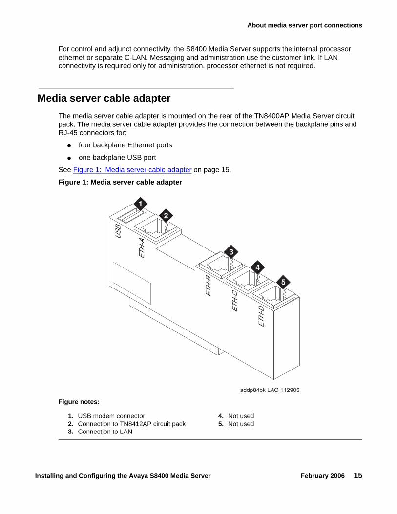
Media server cable adapterThe media server cable adapter is mounted on the rear of the TN8400AP Media Server circuit pack. The media server cable adapter provides the connection between the backplane pins and RJ-45 connectors for:
● four backplane Ethernet ports
● one backplane USB port
See Figure 1: Media server cable adapter on page 15.
Figure 1: Media server cable adapter
Figure notes:
1. USB modem connector2. Connection to TN8412AP circuit pack3. Connection to LAN
4. Not used5. Not used
addp84bk LAO 112905
USB
ETH
-A
ETH
-B
ETH
-C
ETH
-D
1
2
3
4
5

Chapter 1: Introduction
16 Installing and Configuring the Avaya S8400 Media Server February 2006
Table 3: Media server cable adapter port labeling on page 16 describes the connections for the media server cable adapter.
Ethernet connectivity with the TN8412AP circuit packThe S8400 Media Server supports connectivity with the TN8412AP (SIPI) circuit pack through a 10/100 BaseT Ethernet twisted pair on the IPSI-2 cable adapter. This interface is for control only - no bearer traffic is carried over this connection. This Ethernet is connected to the Communication Manager Processor complex. The IPSI-2 cable adapter is mounted on the rear of the TN8412AP SIPI circuit pack.
The physical connection between the TN8412AP and the TN8400 circuit packs is made by either:
1. Using a 10/100 Base T Ethernet crossover cable that directly interconnects the appropriate backplane pins of the two circuit packs. This cable plugs into the TN8400AP cable adapter RJ45 ETH-A port and the TN8412AP IPSI-2 adapter RJ45 control port.
2. Connection to the customer LAN.
Table 3: Media server cable adapter port labeling
Location (counting from the top of the adapter)
Port Name Adapter Label
Function
USB Backplane USB modem port
USB Provides power to the USB modem, can hard reset the USB modem, provides a USB modem interface to support Services remote alarming and access.
Top Ethernet Ethernet connectivity with the TN8412AP circuit pack
ETH-A 10/100Base T Mbps Ethernet Interface for the control links - uses crossover cable to connect directly to the SIPI.
Second Ethernet Ethernet connectivity with the LAN
ETH-B 10/100Base T Mbps Ethernet Interface to the customer LAN.Messaging over IP.Connections to adjuncts and IP endpoints.Remote administration over IP.
Third Ethernet Future ETH-C Not used
Bottom Ethernet Future ETH-D Not used

About media server port connections
Installing and Configuring the Avaya S8400 Media Server February 2006 17
IPSI-2 cable adapter on page 17 shows the IPSI-2 cable adapter for the S8412AP SIPI circuit pack.
Figure 1: IPSI-2 cable adapter
Figure 2: Cable adapters on TN8412AP and TN8400AP circuit packs in a G650 on page 18 shows the location of the two backplane adapters on a G650.
Figure notes:
1. D9 connector 2. RJ45 for connection to the TN8400 or LAN
addpipsi LAO 112905
10/100bT ETHERNET
10/100bT ETHERNET
1
2

Chapter 1: Introduction
18 Installing and Configuring the Avaya S8400 Media Server February 2006
Figure 2: Cable adapters on TN8412AP and TN8400AP circuit packs in a G650
Figure notes:
1. Media server cable adapter on the TN8400AP Media Server circuit pack
2. IPSI-2 cable adapter on the TN8412AP SIPI circuit pack
h2dp650b LAO 121605
USB
ETH-A
ETH-B
ETH-C
ETH-D
RS232 DEBUG
10/100bT ETHERNET1
2
About media server port connections
Installing and Configuring the Avaya S8400 Media Server February 2006 19
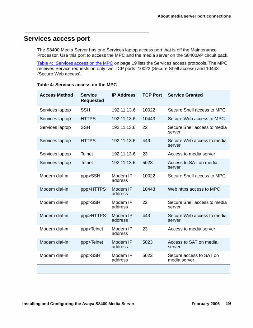
Services access portThe S8400 Media Server has one Services laptop access port that is off the Maintenance Processor. Use this port to access the MPC and the media server on the S8400AP circuit pack.
Table 4: Services access on the MPC on page 19 lists the Services access protocols. The MPC receives Service requests on only two TCP ports: 10022 (Secure Shell access) and 10443 (Secure Web access).
Table 4: Services access on the MPC
Access Method Service Requested
IP Address TCP Port Service Granted
Services laptop SSH 192.11.13.6 10022 Secure Shell access to MPC
Services laptop HTTPS 192.11.13.6 10443 Secure Web access to MPC
Services laptop SSH 192.11.13.6 22 Secure Shell access to media server
Services laptop HTTPS 192.11.13.6 443 Secure Web access to media server
Services laptop Telnet 192.11.13.6 23 Access to media server
Services laptop Telnet 192.11.13.6 5023 Access to SAT on media server
Modem dial-in ppp>SSH Modem IP address
10022 Secure Shell access to MPC
Modem dial-in ppp>HTTPS Modem IP address
10443 Web https access to MPC
Modem dial-in ppp>SSH Modem IP address
22 Secure Shell access to media server
Modem dial-in ppp>HTTPS Modem IP address
443 Secure Web access to media server
Modem dial-in ppp>Telnet Modem IP address
23 Access to media server
Modem dial-in ppp>Telnet Modem IP address
5023 Access to SAT on media server
Modem dial-in ppp>SSH Modem IP address
5022 Secure access to SAT on media server

Chapter 1: Introduction
20 Installing and Configuring the Avaya S8400 Media Server February 2006
About Modem connections Note:
Note: USB modems cannot connect to rotary lines. A Touch Tone line is required.
The TN8400AP Media Server circuit pack supports a USB modem. The modem communicates directly to the maintenance processor or tunnels through to the Communication Manager processor application. The modem provides Avaya Services with remote alarming and dial-in and dial-out access.
Connect the USB modem to port labeled USB on the media server cable adapter. The adapter is mounted on the rear of the TN8400AP Media Server circuit pack.
Modem options are set when you configure the media server. No options are set on the modems themselves.
About Media GatewaysIn a new installation, the S8400 Media Server is installed only in the Avaya G650 Media Gateway.
In a migration the media server is installed only in the following Avaya Media Gateways:
● G600
● CMC1
In addition, the media servers work with Avaya G150, G250, G350, and G700 Media Gateways. These gateways register with the S8400 either through the S8400 Processor Ethernet interface or through a TN799DP C-LAN circuit pack.

About Processor Ethernet
Installing and Configuring the Avaya S8400 Media Server February 2006 21
About Processor Ethernet Like a C-LAN board, Processor Ethernet provides connectivity to IP endpoints, gateways, and adjuncts. The PE interface is a logical connection in the Communication Manager software that uses a port on the NIC in the server. There is no additional hardware needed to implement PE. Starting with release 3.1 of Communication Manager, the PE interface is enabled on theS8400 Media Server allowing enhanced flexibility for connectivity to gateways, endpoints, and adjuncts.Table 5 lists the possible uses of the PE interface for an S8400.
Table 5: Use of the PE interface on the S8400 Media Server
Possible functions of the PE interface
Status of the function on the server
Administration needed
Registration The PE interface is always enabled for registration.
No. The use of the PE interface for registration is enabled automatically by the Communication Manager software.
H.248 gateway registration
H.248 gateway registration is enabled by default on the S8400 Media Server
The H.248 gateway enabled field on the ip-interface procr form defaults to a yes on an S8400 Media Server. You can disable the H.248 registration by changing the H.248 gateway enabled field on the ip-interfaces procr form to a no.
H.323 endpoint registration
H.323 registration is enabled by default on the S8400 Media Server.
The H.323 endpoint enabled field on the ip-interface procr form defaults to a yes on an S8400 Media Server. You can disable H.323 endpoint registration by changing the H.323 enabled field on the ip-interfaces procr form to a no.
Adjunct connectivity Connectivity of adjunct is enabled by default on the S8400 Media Server.
Yes. Adjuncts must be administered on the S8400 Media Server.

Chapter 1: Introduction
22 Installing and Configuring the Avaya S8400 Media Server February 2006
About SSH Secure Shell (SSH) is both a computer program and an associated network protocol designed for logging into and executing commands on a networked computer. SSH provides secure encrypted communications between two untrusted hosts over an insecure network. Avaya recommends using SSH instead of Telnet for most interactive connections to the Avaya media servers and other devices on a customer’s network.
To use SSH, a third-party SSH client must be installed on your computer. PuTTY is one such client available for download from http://www.putty.nl/download.html.
Devices that can be accessed with SSH include:
● Media servers on Release 3.1 of Communication Manager: S8300, S8400, S8500, S8700-series
May include port number reference 5022 for direct SAT access.
● Server Availability Management Processor (SAMP) (used with S8500 Media Server)
May include port number reference 10022 for direct access
● Maintenance Processor Complex (MPC) (used with S8400 Media Server)
May include port number reference 10022 for direct access
● TN2312BP IPSI running firmware version 20 or higher
● TN8412AP SIPI
● TN2602 IP Media Resource 360 running firmware version 212 or higher
● Expanded Meet-Me Conferencing (EMMC) and the S6100 Media Server
● SIP server
● G250 and G350 media gateways
● C360 Ethernet switches
! Important:Important: G700 does not allow the use of SSH. From within a media server's Linux
command line, you can use SSH to access the G250 and G350, but you must use telnet to access the G700. In this case, the server is the SSH client, not PuTTY.

High level overview of installation process
Installing and Configuring the Avaya S8400 Media Server February 2006 23
High level overview of installation process The installation process is completed in stages. Some stages can be completed in parallel, and others require that certain tasks be accomplished before the stages can be completed. The order that the particular stages are completed depends on local practice and the personnel available. The high level stages are listed below.
Installing and cabling the media gatewaysInstall and connect the media gateways before installing and configuring the S8400 Media Server. The media gateways must be installed and powered up to effectively complete many of the other stages. A powered-up media gateway is required for software installation and configuration on the S8400 Media Server and programming of the SIPI circuit pack. See the Quick Start documentation for your system for instructions.
Installing Avaya Communication ManagerA new S8400 Media Server comes with a blank hard drive and a blank solid state device (SSD). Use the bootable software distribution CD-ROM to install the Linux operating system and Avaya Communication Manager.
Configuring the MPCThe Maintenance Processor Complex (MPC) monitors various components and environmentals on the media server. The board comes installed from the factory with Avaya defaults but must be configured to fit your specific installation. The MPC is administered automatically through the Avaya Installation Wizard.
Configuring the media serverUse the Avaya Installation Wizard to configure the media server. You must have the filled-out Electronic Preinstallation Worksheet (EPW) that provides the customer’s network information needed for configuring the network components. As part of the Wizard, you install the license and Avaya authentication files. This stage is done after installing the software.

Chapter 1: Introduction
24 Installing and Configuring the Avaya S8400 Media Server February 2006
Translating the SIPIWhen configuring the media server (or both media servers in a duplicated system), the Avaya Installation Wizard installs the license file.The SIPI circuit packs must be translated within 30 minutes after the license file is installed.
Completing the installation administrationFinish the media server installation by clearing alarms, enabling alarm reporting, backing up the server files, and registering the configuration.
Testing the finished installationThis stage verifies the complete configuration operation and is the last task.

Configuration of the SNMP modules in the UPS
Installing and Configuring the Avaya S8400 Media Server February 2006 25
Chapter 2: SNMP Configuration
After the control network equipment is installed and connected, configure the SNMP modules to send alarms (traps) to the media servers.
Configure:
● the SNMP modules in each UPS (if supplied by Avaya)
● the SNMP Subagent in the Avaya Ethernet switch (if supplied by Avaya)
First configure the SNMP agents. Then install Avaya Communication Manager on the media server, configure the media server, and verify its operation. In a duplicated system, install Avaya Communication Manger on the first media server and verify its operation before you repeat the process on the second media server.
This section covers Configuration of the SNMP modules in the UPS on page 25
Configuration of the SNMP modules in the UPS Note:
Note: These instruction apply only if using a new, Avaya-supplied uninterruptible power supply (UPS) with a simple network management protocol (SNMP) module. Do not use these procedures to set traps on a non-Avaya-supplied UPS.
The SNMP module in the UPS must be administered so it reports alarms to the media server when the hardware experiences problems. The module reports the loss of commercial power and the depletion of battery resources.
For the SNMP module to properly report alarms, a unique IP address for the UPS must be configured on both the SNMP module and the media server. This IP address can be a customer-provided one or the Avaya-provided default one. At a minimum, the following items must be configured:
● IP address
● Subnet mask
● Gateway IP address
● Trap receiver IP address
● Community string (get, set, trap)

Chapter 2: SNMP Configuration
26 Installing and Configuring the Avaya S8400 Media Server February 2006
Because the SNMP module is manufactured by a third party, we do not know which brand, model, or firmware load the factory is shipping. Therefore, we cannot provide specific instructions in this document on how to connect to and configure the SNMP module. See the documentation that comes with the SNMP module. The default password and the configuration commands are in the local configuration section of the User Guide.
Default UPS IP addressesAdminister the SNMP module in the UPS following the steps in Administering the SNMP module on page 27. The default IP addresses for the UPS are shown in the table.
Preparing to configure the SNMP moduleBefore you configure the SNMP module, make sure you have the hardware connected correctly and all the information you need.
● Ensure you are plugged into the correct administration port on the SNMP module.
● Ensure the UPS is plugged into a nonswitched electrical outlet.
Note:Note: Avaya Terminal Emulation and HyperTerminal are supported terminal emulation
applications.
● When using your terminal emulation application, ensure that your laptop communication protocol has the following port settings:
- 9600 baud- No parity- 8 data bits- 1 stop bit- No flow control
IP address for UPS 198.152.254.239
Subnet mask for UPS 255.255.255.0
Gateway address for UPS 198.152.254.201
IP address forTrap receiver (media server)
customer provided

Configuration of the SNMP modules in the UPS
Installing and Configuring the Avaya S8400 Media Server February 2006 27
● If a Network Management System (NMS) is going to monitor the UPS, coordinate the assignment of community names with the network administrator.
If an NMS is not going to monitor the UPS, set the community names to unique string values.
! SECURITY ALERT:!
SECURITY ALERT: The Get and Set, community name strings are initially configured with default values of Public and Private, respectively. These community name strings function as passwords for their respective SNMP operation. It is always a good idea to change these community name strings to something other than the default values. If the defaults are left in place, they could result in a serious security issue.
See Setting selected traps (alarming) on page 28 for information on which traps to set.
● If the control network is nondedicated (going over the customer's network), make sure that the 162/udp port for input to server is enabled (the default is disabled). Otherwise, the media server cannot receive the traps from the UPS(s). See Enabling firewall settings on page 40.
Administering the SNMP module
Note:Note: Use the default addresses in the tables.
1. Connect the services laptop computer (RS-232 serial port) to the DB-9 connector on the back of the SNMP module for UPS1 using the DB-9 to DB-9 serial cable supplied with the SNMP module.
2. Open a VT-100 terminal emulation session on the services laptop.
3. Set the IP address for the UPS.
4. Set the subnet mask for the UPS.
5. Set the gateway address for the UPS.
6. Set the IP address of the trap receiver (media server) for the UPS.
7. Set the SNMP community name string for Get, Set, and Trap. See Setting selected traps (alarming) on page 28 for information on which traps to set.
8. When completed, disconnect the services laptop computer from the UPS.
9. Connect one end of a CAT5 straight-through cable to the RJ45 connector on the UPS SNMP module and the other end to the next available port on the Ethernet switch for Control Network A (CNA).
For a connectivity guide, see the Quick Start for Hardware Installation: Avaya S8400 Media Server in an Avaya G650 Media Gateway (03-300705).

Chapter 2: SNMP Configuration
28 Installing and Configuring the Avaya S8400 Media Server February 2006
Setting selected traps (alarming) The default is to set all traps, which can result in large log entries. However, only a few traps need to be set. See the User Guide that comes with the SNMP module for the menus and commands for setting these traps.
Set the following traps:
● UPS on Battery—Indicates AC fail with pending shutdown based on battery reserve available
● UPS in Bypass—Failure either Failed UPS or overload
● Replace battery—Failure of periodic (28-day) battery test indicating battery needs to be replaced.

Clearing the ARP cache on the laptop
Installing and Configuring the Avaya S8400 Media Server February 2006 29
Chapter 3: Communication Manager Installation
A new media server comes with a blank hard drive and a blank solid state device (SSD). Use the bootable software distribution CD-ROM to install the Linux operating system and Avaya Communication Manager.
This chapter covers the following tasks:
● Clearing the ARP cache on the laptop on page 29
● Connecting the CD/DVD drive to the media server on page 30
● Powering up the media server on page 30
● Accessing the media server on page 30
● Configuring Telnet for Windows 2000/XP on page 31
● Installing Avaya Communication Manager on page 32
Clearing the ARP cache on the laptop Depending on the operating system on the Services laptop computer, you might need to clear the Address Resolution Protocol (ARP) cache before entering a new IP address. If you enter an IP address and your computer cannot connect, try clearing the cache.
1. On your laptop computer, click Start > Run to open the Run dialog box.
2. Type command and press Enter to open a MS-DOS Command Line window.
3. Type arp -d 192.11.13.6 and press Enter to clear the Address Resolution Protocol (ARP) cache in the laptop.
● The command line prompt appears when the cache is cleared.
● The phrase The specified entry was not found appears when the ARP cache does not contain the specified IP address.

Chapter 3: Communication Manager Installation
30 Installing and Configuring the Avaya S8400 Media Server February 2006
Connecting the CD/DVD drive to the media serverConnecting the CD/DVD drive to the media server
Note:Note: The CD or DVD drive must be placed with 5 degrees of level.
1. When using the DVD drive,
a. Plug one end of the power cord into the DVD drive and plug the other end into an electrical outlet.
b. Set the small switch on the side of the DVD drive to "EXT."
2. Connect the USB cable to the USB port on the faceplate of the S8400 Media Server.
3. When using the DVD drive, connect the other end of the USB cable to the DVD drive. (The USB cable is not detachable from the CD drive).
Note:Note: Immediately place the Avaya Communication Manager CD into the external
CD-ROM drive.
Powering up the media server Note:
Note: The G650 media gateway must have power.
1. Pull the TN8400 circuit pack out far enough to extinguish all LEDs.
2. Carefully slide the circuit pack back in to reboot the system.
Accessing the media server 1. Connect the laptop to the services port on the faceplate of the media server using a
crossover cable.
2. Wait at least 3 minutes after powering up before starting a Telnet session to access the information on the CD.

Configuring Telnet for Windows 2000/XP
Installing and Configuring the Avaya S8400 Media Server February 2006 31
Configuring Telnet for Windows 2000/XP
You can set the Microsoft Telnet application to send a carriage return (CR) and line feed (LF) whenever you press Enter. The installation program sees this as 2 key presses. If you are running Windows 2000/XP, correct this before you copy the Remaster Program to the SDD.
To configure telnet for Windows 2000/XP:
1. Click Start > Run to open the Run dialog box.
2. Type telnet and press Enter to open a Microsoft Telnet session.
3. Type display and press Enter to see the current settings.
● Close the dialog box if the Line feed mode - Causes return key to send CR appears.
● Continue if New line mode - Causes return key to send CR & LF appears.
4. Type unset crlf and press Enter.5. Type display and press Enter to verify that Line feed mode - Causes return key to
send CR appears.
6. Close the dialog box.

Chapter 3: Communication Manager Installation
32 Installing and Configuring the Avaya S8400 Media Server February 2006
Installing Avaya Communication Manager
Install Avaya Communication Manager on the media server using the following steps.
Note:Note: Use a telnet session to access the information on the CD.
1. From the laptop Start menu, click Start > Run to open the Run dialog box.
2. Type telnet 192.11.13.6 and press Enter to view the first screen.
Note:Note: To navigate on these screens, use the arrow keys to move to an option, then
press the space bar to select the option. Press Enter to submit the screen.
3. Select Install, ensure that <OK> is highlighted, and press Enter.

Installing IA 770 INTUITY AUDIX Messaging
Installing and Configuring the Avaya S8400 Media Server February 2006 33
4. On the Select Release Version screen, ensure that the Build line and <OK> is highlighted. Press Enter to partition the hard disk drive and reformat the partitions.
Once the drive is properly configured, the program starts the installation process and reports the progress.
These processes can take up to 20 minutes. When the media server is ready to reboot, the CD-ROM drive drawer opens. You must remove the CD from the drive at this time.
The reboot can take up to 3 minutes. The telnet session drops automatically.
Installing IA 770 INTUITY AUDIX Messaging See IA 770 INTUITY AUDIX Installation, Upgrades, and Troubleshooting for information on installing the optional IA 770 messaging software.

Chapter 3: Communication Manager Installation
34 Installing and Configuring the Avaya S8400 Media Server February 2006
Opening the Maintenance Web Interface
Installing and Configuring the Avaya S8400 Media Server February 2006 35
Chapter 4: Media server configuration
After installing the Communication Manager software, you must configure the media server using the Avaya Installation Wizard.
This section covers the following tasks:
● Opening the Maintenance Web Interface on page 35
● Copying files to the media server on page 36
● Enabling Network Time Servers on page 37
● Using the Installation Wizard on page 38
● Configuring the modem on page 41
Note:Note: Make sure you have the filled-out Electronic Preinstallation Worksheet (EPW)
before beginning this process.
Note:Note: Make sure your networking and Web browser settings are correct. In
Appendix A: Media server access, see Configuring the network for Windows 2000/XP on page 80.
Opening the Maintenance Web InterfaceYou can use the Maintenance Web Interface to copy files from the Services laptop to the media server, and to perform other configuration tasks.
To access the media server and open the Maintenance Web Interface:
1. Launch a Web browser.
2. In the Address field, type 192.11.13.6 and press Enter to bring up the login Web page.
Note:Note: The first time you attempt to log in, you get a Web page asking you to install a
security certificate. Follow the instructions for your particular browser to accept the certificate. You can also install the certificate on your services laptop computer by following the instructions in your browser’s online help.
3. Log in as craft and use the initial craft password.
4. When asked Do you want to suppress alarms?, select Yes.

Chapter 4: Media server configuration
36 Installing and Configuring the Avaya S8400 Media Server February 2006
Note:Note: On the initial Web page, some items may not appear at first. These include
Launch Avaya Station Administration Wizard in the Administration section and the Upgrade section including Launch Upgrade Tool.
5. Click Launch Maintenance Web Interface.
Copying files to the media serverYou can use the Maintenance Web Interface to copy license and authentication files, service packs, and MPCupdate files from the Services laptop to the media server.
1. On the Maintenance Web Interface, under Miscellaneous, select Download Files.
2. Select File(s) to download from the machine I’m using to connect to the server.3. Click Browse next to the top field to open the Choose File window on your computer. Find
the files that you need to copy to the media server.
4. Click Download to copy the file(s) to the media server.
The files are automatically copied to the default file location.

Enabling Network Time Servers
Installing and Configuring the Avaya S8400 Media Server February 2006 37
Enabling Network Time Servers
! Important:Important: Avaya strongly recommends enabling Network Time Protocol (NTP) and
configuring at least one network time server. If a network time server is not used, the Date/Time settings on the media server should be reset regularly (at least monthly), using the Maintenance Web Interface. The network time strategy should be determined by the network administrator.
Enabling Network Time Protocol allows you to specify one, two, or three network time servers to provide accurate time-of-day data to the clocks on the media servers. The network time servers, in turn, get their source timing from one of several available, highly accurate, time services on the Internet.
To use a network time server, the NTP service must be enabled. The Avaya Installation Wizard prompts for enabling the NTP service.
If you are not using the Installation Wizard, follow these steps:
1. Open the Maintenance Web Interface
2. Select Configure Server under Server Configuration
3. Select Configure individual services and go to Configure Time Server
4. Enter the NTS information on the Configure Time Server screen and click Change5. Click on the Firewall link under Security.
6. Enable ntp 123/udp in the "Output from Server" column by clicking on the checkbox.
Note:Note: It is not necessary to enable the "Input to Server" ntp service but if it is already
enabled, you don’t have to disable it.
In the next section, Using the Installation Wizard on page 38, the Avaya Installation Wizard prompts for information about network time servers. When prompted, enter the DNS name or IP address for the primary (and secondary and tertiary, if any) network time server. If you enter a DNS name instead of an IP address for the network time server, the DNS server IP address must be specified. You are prompted for this information by the Installation Wizard.
If you are not using the Installation Wizard, the network time servers can be configured using the Configure Server function on the Maintenance Web Interface.
For detailed information about NTP, see RFC 958.

Chapter 4: Media server configuration
38 Installing and Configuring the Avaya S8400 Media Server February 2006
Using the Installation Wizard Use the Avaya Installation Wizard (IW) to automatically:
● Configure the media server
● Configure the Maintenance Processor Complex
● Install the license file
Note:Note: You can install the license file without being physically connected to the reference
SIPI. However, you have only 30 minutes before it checks the serial number on the SIPI. To get another 30 minutes, you can restart the clock by restarting the media server. In a SAT session, type reset system 1.
● Install the Avaya authentication files
● Install software updates
You can use the IW in two ways:
● You can import the data from the filled-out Electronic Preinstallation Worksheet (EPW). When the IW prompts to import the Preinstallation Worksheet, click Import EPW and browse to the location of the EPW file on your laptop. The IW will open the EPW and upload the configuration data.
● You can type in the information manually using the filled-out EPW as a guide. The IW will prompt you to enter the configuration data for each step in the Configure Server section.
To run the Avaya Installation Wizard:
1. Launch the Web browser.
2. Enter 192.11.13.6 and press Enter to bring up the login Web page.
3. Log in as craft and use the initial craft password.
4. Click Launch Avaya Installation Wizard.
5. Follow the Wizard prompts, using Help on each page for more information.

Verifying MPC IP information
Installing and Configuring the Avaya S8400 Media Server February 2006 39
Verifying MPC IP information The Maintenance Processor Complex (MPC) page is under Optional Services in the Wizard configuration process. Verify that the IP information was retrieved from the EPW. If the information is not there, manually complete all fields.
To allow services access to the remote maintenance board through a crossover cable, verify the information in these fields:
For services laptop access:
● IP Address field - 192.11.13.6● Subnet Mask field - 255.255.255.252If the information is not there, fill in the fields manually.
Installing MPC firmware See Maintenance Procedures for Avaya Communications Manager 3.1, Media Gateways and Servers for additional details on updating MPC firmware.
The MPC firmware may need to be updated, depending on the currently installed version. The versions that require updates should be included in your project planning information.
To update the firmware version:
1. Check the firmware version.
- Use SSH to access the media server and login.- Enter sampcmd samp-update status.- Check the firmware version displayed.
2. If the firmware needs to be updated, use Download Files from the Maintenance Web Interface to copy the firmware file to the media server.
3. Use SSH to access the media server and login.
4. Enter sampupdate to initiate the update process.
The update process takes approximately 5 minutes.
5. Enter y in response to the question, Commit this software?

Chapter 4: Media server configuration
40 Installing and Configuring the Avaya S8400 Media Server February 2006
Verifying media server connection to the customer’s LAN (if provided)
1. Under Diagnostics, click Ping.
2. Select Host Name Or IP Address and type in the IP address of a computer on the network.
3. Click Execute Ping.
4. Verify that the ping was successful, indicating that the media server is connected to the customer’s network.
5. If DNS is administered, type in the host name of a computer on the network.
6. Click Execute Ping.
7. Verify that the ping was successful, indicating that DNS is working.
If possible, have a customer representative do the following test from a computer on the network:
1. Click Start > Run to open the Run dialog box.
2. Type command and click OK to open an MS-DOS command window.
3. Type ping serveripaddress and click OK, where serveripaddress is the IP address of the media server.
4. Verify that the ping was successful.
5. If DNS is administered, type ping servername and press Enter, where servername is the host name of the media server.
6. Verify that the ping was successful.
Enabling firewall settings For the media server to receive SNMP traps from the UPS and Avaya Ethernet switch, you must enable the snmptrap, 162/udp port. The default is disabled.
1. Under Security, click Firewall.2. Click Advanced Settings . . . to view the second page.
3. Scroll down until you see snmptrap, port 162/udp.
4. Select the box in the Input to Server column (far left) next to it.
Configuring the modem
Installing and Configuring the Avaya S8400 Media Server February 2006 41
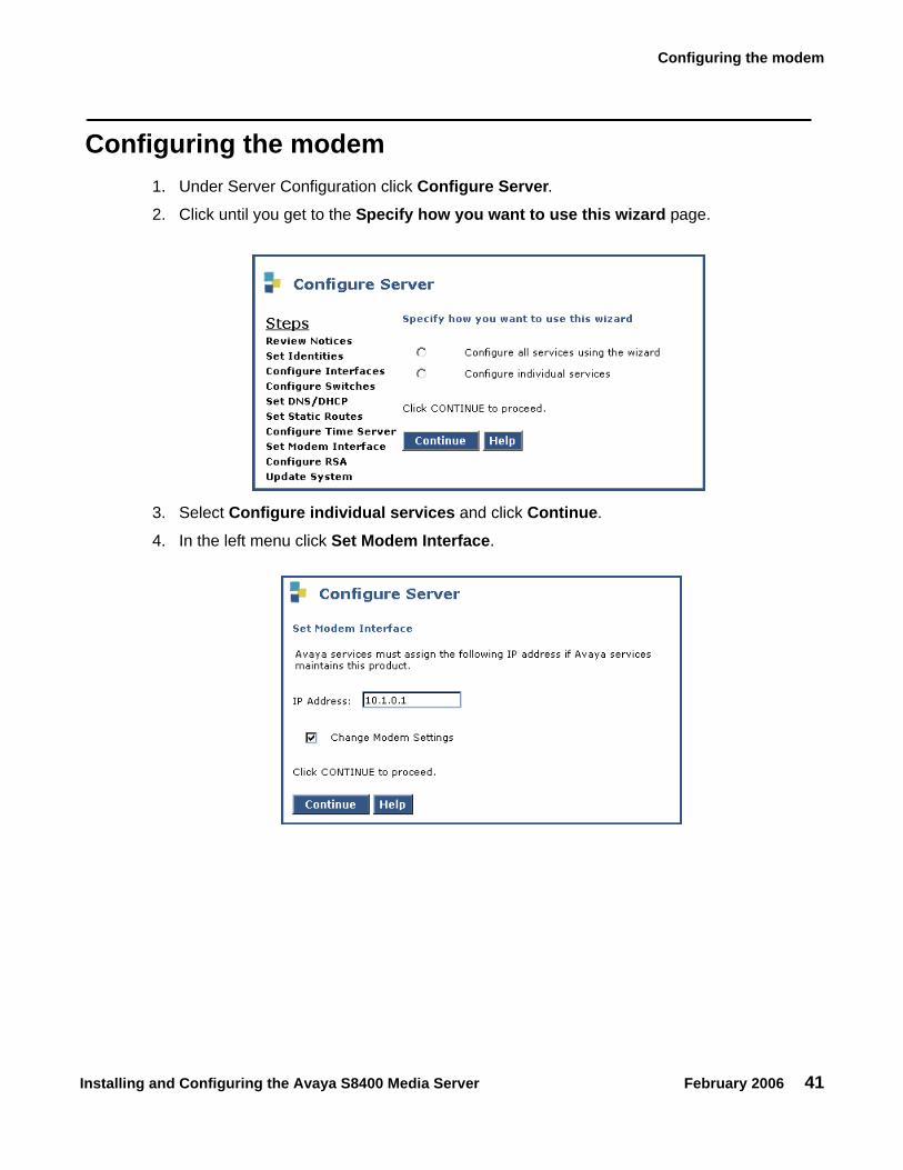
Configuring the modem 1. Under Server Configuration click Configure Server.2. Click until you get to the Specify how you want to use this wizard page.
3. Select Configure individual services and click Continue.
4. In the left menu click Set Modem Interface.

Chapter 4: Media server configuration
42 Installing and Configuring the Avaya S8400 Media Server February 2006
5. Select the Change Modem Setting and click Continue.
6. In the AT String field, type the initialization commands appropriate for your modem and country of operation. Click Help for guidance on what to enter.
For example, to change the country code to Japan, type AT%T19,0,10.
7. Click Change.
The system responds with a message indicating a successfully added modem route.
8. Click Close Window.

Installing and Configuring the Avaya S8400 Media Server February 2006 43
Chapter 5: IP interface translations
To administer SIPI circuit packs, issue Communication Manager SAT commands on a terminal emulation program.
For Communication Manager terminal emulation, use a program such as Avaya Native Configuration Manager, Avaya Terminal Emulation, or HyperTerminal.
You also can use Avaya Site Administration (ASA) to issue SAT commands. You must use ASA Release 2.1, update 1, or a later version to administer new features in Release 3.0 of Avaya Communication Manager.
Perform these tasks to administer SIPI circuit packs:
● Starting SAT terminal emulation on page 44
● Inputting initial system translations on page 44
● Adding media gateways on page 44
● Enabling SIPI on page 45
● Adding the SIPI to the system on page 46
● Setting alarm activation level on page 47
● Saving translations on page 47

Chapter 5: IP interface translations
44 Installing and Configuring the Avaya S8400 Media Server February 2006
Starting SAT terminal emulation For Communication Manager SAT terminal emulation, use a program such as Avaya Native Configuration Manager or HyperTerminal. You also can use Avaya Site Administration to issue SAT commands.
1. On the services laptop, open a VT-100 terminal emulation session.
2. If using a serial modem connection, administer the terminal emulation port settings:
● 9600 baud
● No parity
● 8 data bits
● 1 stop bit
● No flow control
● 5023 for the port
3. Log into the media server as craft.
Inputting initial system translations If system translations were prepared offsite, input the translations and reset the media server. If the translations are not available, enter minimal translations to verify connectivity to the port networks.
1. Type save translation and press Enter to save the translations to the hard drive.
2. Type reset system 4 and press Enter to have the software read the copied translations.
Adding media gateways Note:
Note: If system translations have been loaded on the media server, media gateways do not need to be added in order to administer the SIPI.

Enabling SIPI
Installing and Configuring the Avaya S8400 Media Server February 2006 45
1. Type add cabinet n (where n is the cabinet number) and press Enter for each stack of Media Gateways controlled by one TN8412AP SIPI circuit pack.
A cabinet is defined as up to five G650 Media Gateways mounted in a rack and TDM-connected.
2. Fill in the location and carrier type for media gateways 2(B), 3(C), 4(D), and 5(E).
Enabling SIPI These steps enable the SIPI circuit pack and allow the SIPI to control the port network.
1. Type change system-parameters ipserver-interface and press Enter. 2. On the IP Server Interface System Parameters screen, verify that the Primary Control
Subnet Address is correct.
The subnet address must match the most significant 3 octets (the first 3 groups of digits in the subnet address) of the Media Gateway’s Server IP address (the server that controls the port network). Use configure server on the Maintenance Web Interface to see the IP address to match.
An asterisk (*) to the right of the Subnet Address field means that the subnet address displayed is not the correct one. Avaya Communication Manager does not have the subnet information.
add cabinet 1 Page 1 of 1CABINET
CABINET DESCRIPTION Cabinet: 1 Cabinet Layout: G650-rack-mount-stack Cabinet Type: expansion-portnetwork
Number of Portnetworks: 1Survivable Remote EPN? n
Location: 1 IP Network Region:1Cabinet Holdover: A-carrier-only
Room: Floor: Building:
CARRIER DESCRIPTION Carrier Carrier Type Number
E not-used PN 09 D not-used PN 09 C not-used PN 09 B G650-port PN 09 A G650-port PN 09
Chapter 5: IP interface translations
46 Installing and Configuring the Avaya S8400 Media Server February 2006
3. If the information in the Subnet Address field is not correct, use the Maintenance Web Interface to change the media server configuration to match the Server IP address in configure server. Under Server Configuration and Upgrades, click Configure Server to change the media server configuration. Then return to this procedure.
4. Set the Switch Identifier field to the switch ID letter (A through J; A is the default setting).
5. Set the IPSI Control of Port Networks field to enabled.
6. Press Enter to save the translations.
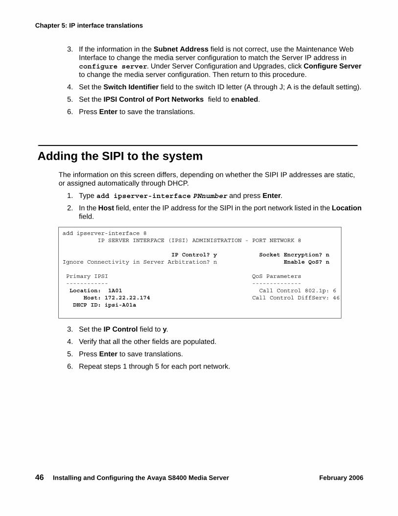
Adding the SIPI to the system The information on this screen differs, depending on whether the SIPI IP addresses are static, or assigned automatically through DHCP.
1. Type add ipserver-interface PNnumber and press Enter.2. In the Host field, enter the IP address for the SIPI in the port network listed in the Location
field.
3. Set the IP Control field to y.
4. Verify that all the other fields are populated.
5. Press Enter to save translations.
6. Repeat steps 1 through 5 for each port network.
add ipserver-interface 8 IP SERVER INTERFACE (IPSI) ADMINISTRATION - PORT NETWORK 8
IP Control? y Socket Encryption? nIgnore Connectivity in Server Arbitration? n Enable QoS? n
Primary IPSI QoS Parameters ------------ -------------- Location: 1A01 Call Control 802.1p: 6 Host: 172.22.22.174 Call Control DiffServ: 46 DHCP ID: ipsi-A01a

Setting alarm activation level
Installing and Configuring the Avaya S8400 Media Server February 2006 47
Setting alarm activation level 1. Type change system-parameters maintenance and press Enter.2. In the CPE Alarm Activation Level field, select none, warning, minor, or major,
according to customer request, and press Enter.
Saving translations Type save translation and press Enter to save the translations to the hard drive.

Chapter 5: IP interface translations
48 Installing and Configuring the Avaya S8400 Media Server February 2006

Installing and Configuring the Avaya S8400 Media Server February 2006 49
Chapter 6: IP interface configuration
This chapter covers the following tasks:
● Programming the SIPI for static addressing on page 50
● Verifying that SIPI is translated on page 54
● Verifying connectivity to media server on page 54
● Upgrading the SIPI firmware version (if necessary) on page 54
● Enabling control of SIPI on page 55
● Verifying license status on page 55
You must program the TN8412AP Server IP Interface (SIPI) to avoid going into No License Mode.
SIPI address configuration The SIPI circuit pack normally uses static IP addressing only.
Perform the task in Programming the SIPI for static addressing on page 50.
Chapter 6: IP interface configuration
50 Installing and Configuring the Avaya S8400 Media Server February 2006
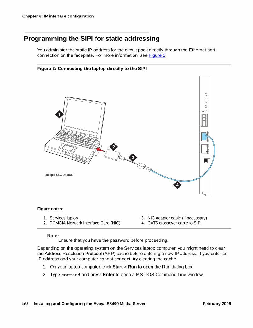
Programming the SIPI for static addressing You administer the static IP address for the circuit pack directly through the Ethernet port connection on the faceplate. For more information, see Figure 3.
Figure 3: Connecting the laptop directly to the SIPI
Note:Note: Ensure that you have the password before proceeding.
Depending on the operating system on the Services laptop computer, you might need to clear the Address Resolution Protocol (ARP) cache before entering a new IP address. If you enter an IP address and your computer cannot connect, try clearing the cache.
1. On your laptop computer, click Start > Run to open the Run dialog box.
2. Type command and press Enter to open a MS-DOS Command Line window.
Figure notes:
1. Services laptop2. PCMCIA Network Interface Card (NIC)
3. NIC adapter cable (if necessary)4. CAT5 crossover cable to SIPI
cadlipsi KLC 031502
1
2
CLK
SERVICE
NETWORK
3
4

SIPI address configuration
Installing and Configuring the Avaya S8400 Media Server February 2006 51
3. Type arp -d 192.11.13.6 and press Enter to clear the Address Resolution Protocol (ARP) cache in the laptop.
● The command line prompt appears when the cache is cleared.
● The phrase The specified entry was not found appears when the ARP cache does not contain the specified IP address.
4. To log into the SIPI, type telnet 192.11.13.6 and press Enter.Prompt = [IPSI]:
Note:Note: While connected to the SIPI, type help or ? to obtain online help. Most
commands have two or three letter abbreviations.
5. Type ipsilogin and press Enter. The abbreviated command is il.
Note:Note: The craft login used on the SIPI has a different password than the craft login used
on the media servers.
6. Log in as craft.
Prompt = [IPADMIN]:
7. Enter show control interface and then enter show port 1 to see the current control interface settings.
8. To set the control interface, type set control interface ipaddr netmask and press Enter, where ipaddr is the customer-provided IP address and netmask is the customer provided subnet mask.
9. Enter quit to save the changes and exit the IPSI session.

Chapter 6: IP interface configuration
52 Installing and Configuring the Avaya S8400 Media Server February 2006
10. Telnet to 192.11.13.6 and login.
11. Enter show control interface.The IP address, subnet mask, and default gateway information is displayed. Verify that the proper information was entered.
12. If a default gateway is used, enter the gateway IP address withset control gateway gatewayaddr, where gatewayaddr is the customer-provided IP address for their gateway.
13. Enter quit to save the changes and exit the IPSI session.
14. Telnet to 192.11.13.6 and login.
15. Use show control interface to verify the administration.
16. Type exit and press Enter to see the changes.
Setting the VLAN and diffserv parameters1. Log in as craft.
2. Enter show qos to display the quality of service values.
3. If necessary, use the following commands to set the VLAN and diffserv parameters to the recommended values shown.
Note:Note: Use Help to obtain syntax guidelines for these commands.
● Enter set vlan priority 6
● Enter set diffserv 46
● Enter set vlan tag on
● Enter set port negotiation 1 disable
● Enter set port duplex 1 full
● Enter set port speed 1 100
4. Enter show qos to check the administered values.
5. Enter quit to exit.
! Important:Important: Ensure that the port settings on the Ethernet switches are set to the same values
as shown above in these set port commands. Log in to the Ethernet switch and enter show qos.

Resetting the SIPI
Installing and Configuring the Avaya S8400 Media Server February 2006 53
Resetting the SIPI 1. Type reset and press Enter
Answer Y to the warning.
Note:Note: Resetting the SIPI terminates the administration session. If further administration
is required, start a new telnet session.
Note:Note: Control network settings (IP address, subnet mask, and gateway) become
effective when you exit the IPADMIN session.
2. Disconnect the laptop from the faceplate.
3. Check the LCD. Verify that it has an I P with a filled-in V that shows at the bottom. For more information, see Figure 4.
Figure 4: SIPI LED display for static address
Figure notes:
1. SIPI has a static IP address 2. SIPI has connectivity and an IP address
ledl
ip1
KLC
030
502
1
2
CLK
SERVICE
NETWORK

Chapter 6: IP interface configuration
54 Installing and Configuring the Avaya S8400 Media Server February 2006
Verifying connectivity to media server 1. If not already open, open and log in to Maintenance Web Interface as craft.2. Under Diagnostics, click Ping and select Other server(s), All IPSIs, UPS(s), Ethernet
switches to verify connectivity to these units.
3. Click Execute Ping.
4. Verify that all endpoints respond correctly.
Verifying that SIPI is translated 1. Open a SAT session on the media server.
2. Type list ipserver-interface and press Enter.3. Verify that the SIPI circuit pack is translated.
Upgrading the SIPI firmware version (if necessary) You may need to upgrade the firmware on the SIPI.
1. On the Maintenance Web Interface under IPSI Firmware Upgrades, click IPSI Version.
2. Select Query All and click View IPSI Version.
3. Verify the firmware release for the SIPI.
4. If an upgrade is required, follow the procedures in Firmware Download Procedures, which can be accessed from:
ftp://ftp.avaya.com/incoming/Up1cku9/tsoweb/firmware/TNpackFirmwareDownloadInstructions.pdf

Enabling control of SIPI
Installing and Configuring the Avaya S8400 Media Server February 2006 55
Enabling control of SIPI Ensure that the SIPI has the same, current firmware.
1. On the SAT, type change system-parameters ipserver-interface and press Enter.
2. Make sure the IPSI Control of Port Networks: field is set to enabled.
3. Press Enter to effect the changes.
Verifying license status On the Maintenance Web Interface, under Security, click License File and verify that the license mode is now normal.

Chapter 6: IP interface configuration
56 Installing and Configuring the Avaya S8400 Media Server February 2006

Installing and Configuring the Avaya S8400 Media Server February 2006 57
Chapter 7: Post-installation administration
This section covers the following tasks:
● Verifying translations on page 57
● Setting daylight savings time rules on page 58
● Setting locations (if necessary) on page 59
● Verifying date and time on page 60
● Clearing and resolving alarms on page 60
● Backing up files to the compact flash media on page 61
● Enabling alarms to INADS via modem on page 61
● Enabling alarms to INADS via SNMP on page 62
● Before leaving the site on page 62
Verifying translations1. Open a SAT session on the media server.
2. Type list configuration all and press Enter to view all the administered circuit packs in the system.
3. IPSI Refer to your planning documents and check the administration status on the following items:
● list station
● list trunk-group
● list hunt-group
Chapter 7: Post-installation administration
58 Installing and Configuring the Avaya S8400 Media Server February 2006
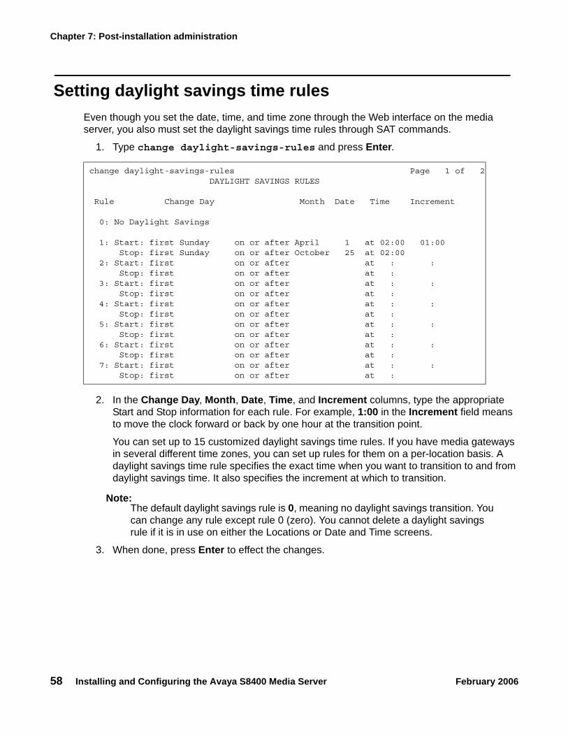
Setting daylight savings time rules Even though you set the date, time, and time zone through the Web interface on the media server, you also must set the daylight savings time rules through SAT commands.
1. Type change daylight-savings-rules and press Enter.
2. In the Change Day, Month, Date, Time, and Increment columns, type the appropriate Start and Stop information for each rule. For example, 1:00 in the Increment field means to move the clock forward or back by one hour at the transition point.
You can set up to 15 customized daylight savings time rules. If you have media gateways in several different time zones, you can set up rules for them on a per-location basis. A daylight savings time rule specifies the exact time when you want to transition to and from daylight savings time. It also specifies the increment at which to transition.
Note:Note: The default daylight savings rule is 0, meaning no daylight savings transition. You
can change any rule except rule 0 (zero). You cannot delete a daylight savings rule if it is in use on either the Locations or Date and Time screens.
3. When done, press Enter to effect the changes.
change daylight-savings-rules Page 1 of 2 DAYLIGHT SAVINGS RULES
Rule Change Day Month Date Time Increment
0: No Daylight Savings
1: Start: first Sunday on or after April 1 at 02:00 01:00 Stop: first Sunday on or after October 25 at 02:00 2: Start: first on or after at : : Stop: first on or after at : 3: Start: first on or after at : : Stop: first on or after at : 4: Start: first on or after at : : Stop: first on or after at : 5: Start: first on or after at : : Stop: first on or after at : 6: Start: first on or after at : : Stop: first on or after at : 7: Start: first on or after at : : Stop: first on or after at :

Setting locations (if necessary)
Installing and Configuring the Avaya S8400 Media Server February 2006 59
Setting locations (if necessary) After you set the daylight savings rules, you must set the locations for all media gateways (cabinets). It is possible to have media gateways in different time zones. Even though you set the date, time, and time zone through the Web interface on the media server, you also must set locations through SAT commands.
1. Type change locations and press Enter.
2. In the ARS Prefix 1 Required for 10-Digit NANP Calls? field, type y.
3. Type the information in the various fields for each media gateway.
Note:Note: In the Name field for location 1, call the media gateway (cabinet) Main.
4. Press Enter to effect the changes.
change locations Page 1 of 5 LOCATIONS
ARS Prefix 1 Required For 10-Digit NANP Calls? y
Number Name Timezone Daylight-Savings Number Plan Offset Rule Area Code 1 Main + 00:00 0 2 CA - 02:00 0 3 : 4 : 5 : 6 : 7 : 8 : 9 : 10 : 11 :

Chapter 7: Post-installation administration
60 Installing and Configuring the Avaya S8400 Media Server February 2006
Verifying date and time Even though you set the date, time, and time zone through the Web interface on the media server, you also must verify the date and time through SAT commands.
1.Type display time and press Enter.
2. Verify that the date and time are correct.
3. Verify that the correct rule (number) is displayed in the Daylight Savings Rule field.
4. If correct, press Cancel.5. If not, go to the Maintenance Web Interface.
6. Under Server, click Set Server Time/Timezone.
7. Verify that the date and time are correct. If not, set it here.
8. Repeat steps 1 through 3.
Clearing and resolving alarms 1. On the Maintenance Web Interface, under Alarms, click Current Alarms.
You can only resolve alarms on the active media server.
2. Select the server alarms to be cleared and click Clear.3. Resolve any major alarms using SAT commands or other standard troubleshooting
procedures.
display time Page 1 of 1 DATE AND TIME
DATE
Day of the Week: Friday Month: November Day of the Month: 8 Year: 2002
TIME
Hour: 14 Minute: 19 Second: 36 Type: Standard
Daylight Savings Rule: 0
WARNING: Changing the date or time may impact BCMS, CDR, SCHEDULED

Backing up files to the compact flash media
Installing and Configuring the Avaya S8400 Media Server February 2006 61
Backing up files to the compact flash mediaNote:
Note: The industrial grade compact flash media provides improved data integrity and reliability, enhanced durability, and extreme endurance. For these reasons Avaya requires the use of an industrial grade compact flash. To read more about the industrial grade compact flash, see the Hardware Description and Reference for Avaya Communication Manager (555-245-207).
1. Insert a 128-Mb compact flash media into the compact flash slot on the media server faceplate.
2. On the Maintenance Web Interface, under Data Backup/Restore, click Backup Now.
3. Select all applicable data sets.
4. Select Local Compact Flash Card back up the data onto the compact flash card.
Optionally, select Format Compact Flash to format a new card.
Note:Note: The compact flash card needs to be formatted only before the first use.
5. Click Start Backup. You are notified when the format is completed (approximately 10 seconds).
Note:Note: Clicking on Start Backup without media in the compact flash drive results in an
error. In this case, repeat the previous steps.
6. Click Backup Status to view the status of the backup.
Enabling alarms to INADS via modemNote:
Note: Enable alarms on both media servers on a duplicated system.
1. Start a telnet session on the media server.
2. Type almenable -d b and press Enter. 3. Type almenable and press Enter to verify that the alarms are enabled.

Chapter 7: Post-installation administration
62 Installing and Configuring the Avaya S8400 Media Server February 2006
Enabling alarms to INADS via SNMP Note:
Note: Do these steps only if a Secure Service Gateway (SSG) is being installed.
Enable alarms on both media servers on a duplicated system.
1. Start a telnet session.
2. Type almsnmpconf -d ipaddress -c communityname and press Enter, where ipaddress is the trap receiver address for the SSG device and communityname is the community string name required by the SSG device.
3. Type almsnmpconf and press Enter.Verify that the correct information was entered.
4. At the prompt, type almenable -s y and press Enter.5. Type almenable and press Enter.
Verify that the SNMP alarm origination is enabled. If used, verify that alarm origination via modem is still enabled.
6. Log off.
Before leaving the siteProvide the default LAN security settings to the customer.
Ensure that the customer knows that remote access to the media server is available only if the the following services are enabled Maintenance Web Interface Firewall screen:
● telnet must be enabled to access Telnet
● https must be enabled to access the Maintenance Web Interface
● def-sat must be enabled to access the SAT commands
● 162/udp must be enabled to receive SNMP traps from the UPS and Avaya Ethernet switch

Installing and Configuring the Avaya S8400 Media Server February 2006 63
Chapter 8: Installation verification
This chapter provides information for testing the media server installation, including:
● Reviewing the status of the control network configuration
● Testing the SIPI circuit packs
● LED status indicators
- Media servers- Uninterruptible power supplies (UPSs)- Circuit packs
Perform these tasks to test the configuration:
● Testing the SIPI circuit pack on page 64
● Testing the license file on page 64
Chapter 8: Installation verification
64 Installing and Configuring the Avaya S8400 Media Server February 2006
Testing the SIPI circuit pack These steps test all the clock and packet interface components within the TN8412AP SIPI circuit pack.
1. In a SAT command line, enter test ipserver-interface <UUC>, where <UUC> is the cabinet and carrier in which the circuit pack is located.
2. Verify that the Test Results screen shows PASS in the results column.
Testing the license file
! Important:Important: Wait at least 30 minutes after you install the Communication Manager license
before you run the test.
1. On a SAT command line, type test license and press Enter.2. Verify that the Test Results screen shows PASS in the results column.
For more detailed information on LEDs, see Maintenance Procedures for Avaya Communication Manager, Media Gateways and Servers, 03-300432.
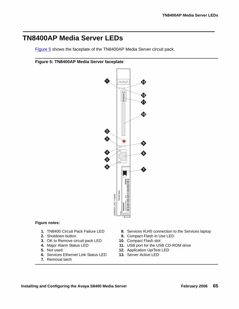
TN8400AP Media Server LEDs
Installing and Configuring the Avaya S8400 Media Server February 2006 65
TN8400AP Media Server LEDsFigure 5 shows the faceplate of the TN8400AP Media Server circuit pack.
Figure 5: TN8400AP Media Server faceplate
Figure notes:
1. TN8400 Circuit Pack Failure LED2. Shutdown button3. OK to Remove circuit pack LED4. Major Alarm Status LED5. Not used6. Services Ethernet Link Status LED7. Removal latch
8. Services RJ45 connection to the Services laptop9. Compact Flash in Use LED
10. Compact Flash slot11. USB port for the USB CD-ROM drive12. Application Up/Test LED13. Server Active LED
7003
2760
4
AVA
YA04
J247
7015
75H
V0
TN84
00A
P
ckdf
8400
LA
O 1
1290
5
7
8
9
1
2
3
4
5
6
10
11
12
13

Chapter 8: Installation verification
66 Installing and Configuring the Avaya S8400 Media Server February 2006
Faceplate interfaces The TN8400AP Media Server maintenance complex has the following faceplate interfaces as shown in Figure 5: TN8400AP Media Server faceplate on page 65:
● TN8400 Circuit Pack Failure LED - This solid red LED is lit when there is a detected TN8400AP Media Server circuit pack failure.
- Solid red during a turn on sequence and during a reset. When turn on or reset is complete and there are no failures, the LED turns off.
- Solid red indicates that there is a failure on the TN8400AP Media Server circuit pack.
● Shutdown button - Hold in the shutdown button for 2 seconds to start a shutdown. The Communication Manager Processor Complex remains in a shutdown state until power is removed and then reapplied. This switch gracefully turns off the operating system and file system so as to not destroy data and require a disk recovery process.
● OK to Remove circuit pack LED - This green LED provides a visual status of the shutdown process.- LED off indicates the system is operational.- Flashing indicates that the shutdown is in progress.- Solid indicates It is safe to remove the TN8400AP Media Server circuit pack from the
carrier or turn off the carrier where the TN8400AP Media Server circuit pack resides.● Major Alarm Status LED - This red LED indicates that a major alarm condition is detected.● Services Ethernet Link Status LED - This green LED shows the status of the Services
Ethernet link. The LED is on when the link is up. The LED flashes any time data transitions are detected.
● Services RJ45 connection to the Services laptop - This Ethernet port provides access to a single 10/100 BaseT Ethernet interface by an RJ-45 connector. This port is connected to the Services laptop, and is used for on-site Services access to the system.
● Compact Flash in Use LED - This yellow LED indicates that the Compact Flash memory is being accessed.
● Compact Flash slot - This slot provides access for storage of translations and selection application data.
● USB port for the USB CD-ROM drive - Used to communicate with peripheral equipment such as a USB CD/DVD ROM for software/firmware updates. Do not connect the modem to this port.
● Server Active LED - This green LED:- The LED is on when the Maintenance Processor detects that the primary application of
the Communication Manager Processor is loaded and running.- The LED is off during a power-on reset or when the system is shutting down.- The LED flashes when a diagnostic /self test is running.

TN8400AP Media Server LEDs
Installing and Configuring the Avaya S8400 Media Server February 2006 67
● Application Up/Test LED - This yellow LED indicates that the S8400 has an active communication path interactively communicating with its SIPI (TN8412).
LED descriptions Table 6: Avaya S8400 Media Server LED descriptions on page 67 lists the description of each LED on the faceplate of the S8400 Media Server and its function.
Table 6: Avaya S8400 Media Server LED descriptions
LED Name Color Power on Reset
BIOS Boot
OS and SW Boot
OS Up* App Active
Shutdown in Progress
Shutdown Complete
TN8400 Circuit Pack Failure†
Red On On On Off - SW‡ Maintains current status
Maintains current status
Maintains current status
OK to Remove Green Off Off Off Off Off Flash On
Major Alarm Status
Red On On Off - SW Off - SW Maintains current status
Maintains current status
Maintains current status
Services Ethernet Link Status
Green Off N/A N/A Link Status Link Status Unknown Off
CompactFlash in Use
Yellow On On Off Off§ - SW Off* Off* Maintains current status
Application is Up/Test
Green On¶ Off Off Off When CM is up, LED is on
Off - SW Off
Server Active** Yellow Off Off Off On when communication is established with the SIPI
Maintains current status
Off Off
*. The Communication Manager Processor complex is running with its operating system.
†. LED lights when on-board hardware or software detects an S8400 failure or during a Communication Manager Processor reboot.
‡. The Maintenance Processor turns on the S8400 Circuit Pack Failure LED when it detects that the Communication Manager Processor is booting. When the Communication Manager Processor completes the boot activities, the processor sends the Maintenance Processor a message requesting that the S8400 Circuit Pack Failure LED be turned off. This LED is turned off unless the hardware or software detects a failure on the circuit pack.
§. LED is turned on by the software when the Compact Flash is accessed.
¶. The LED is on during its power-up self tests.
**. The Server LED is on when the S8400 has an active communication path interactively communicating with its SIPI (TN8412AP).

Chapter 8: Installation verification
68 Installing and Configuring the Avaya S8400 Media Server February 2006
UPS LEDs The UPS LEDs flash briefly after the UPS is plugged in. The Normal mode LED flashes after a self-test, indicating that the UPS is in Standby mode.
For more information, see the UPS user’s guide that comes with the Powerware UPS.
Figure 6: LEDs on Powerware 9125 UPS
Figure notes:
1. Normal mode indicator2. Battery mode indicator3. Bypass mode indicator4. Test/Alarm reset button
5. Off button6. On button7. Bar graph indicators8. Alarm indicators
12
3
4 5 6
7
8
ledlups KLC 030102

TN8412AP SIPI LEDs
Installing and Configuring the Avaya S8400 Media Server February 2006 69
TN8412AP SIPI LEDs Note:
Note: The TN8412AP SIPI faceplate is the same as the TN2312BP IPSI faceplate.
TN8412AP Server IP Interface (SIPI) circuit pack LEDs include:
● standard LEDs and connector slots (TN8412AP SIPI circuit pack faceplate (graphic shows IPSI) on page 70)
● programmable LED display, which indicates
- type of IPSI IP address: static (shows I P) - connectivity

Chapter 8: Installation verification
70 Installing and Configuring the Avaya S8400 Media Server February 2006
Figure 7: TN8412AP SIPI circuit pack faceplate (graphic shows IPSI)
Figure notes:
1. Red LED2. Green LED3. Amber LED4. Yellow LED (Tone Clock status)5. Emergency Transfer LED
6. Services RJ45 connector7. Network Control RJ45 connector8. 4-character LED display9. Pushbutton switch
10. Slot for maintenance cable
ckdf
ips2
KLC
091
403
CLK
SERVICE
NETWORK
7000
6064
3
AVA
YA01
DR
0614
2246
TN
2312
AP
IP
SI
3
4
5
8
9
1
2
6
7
10
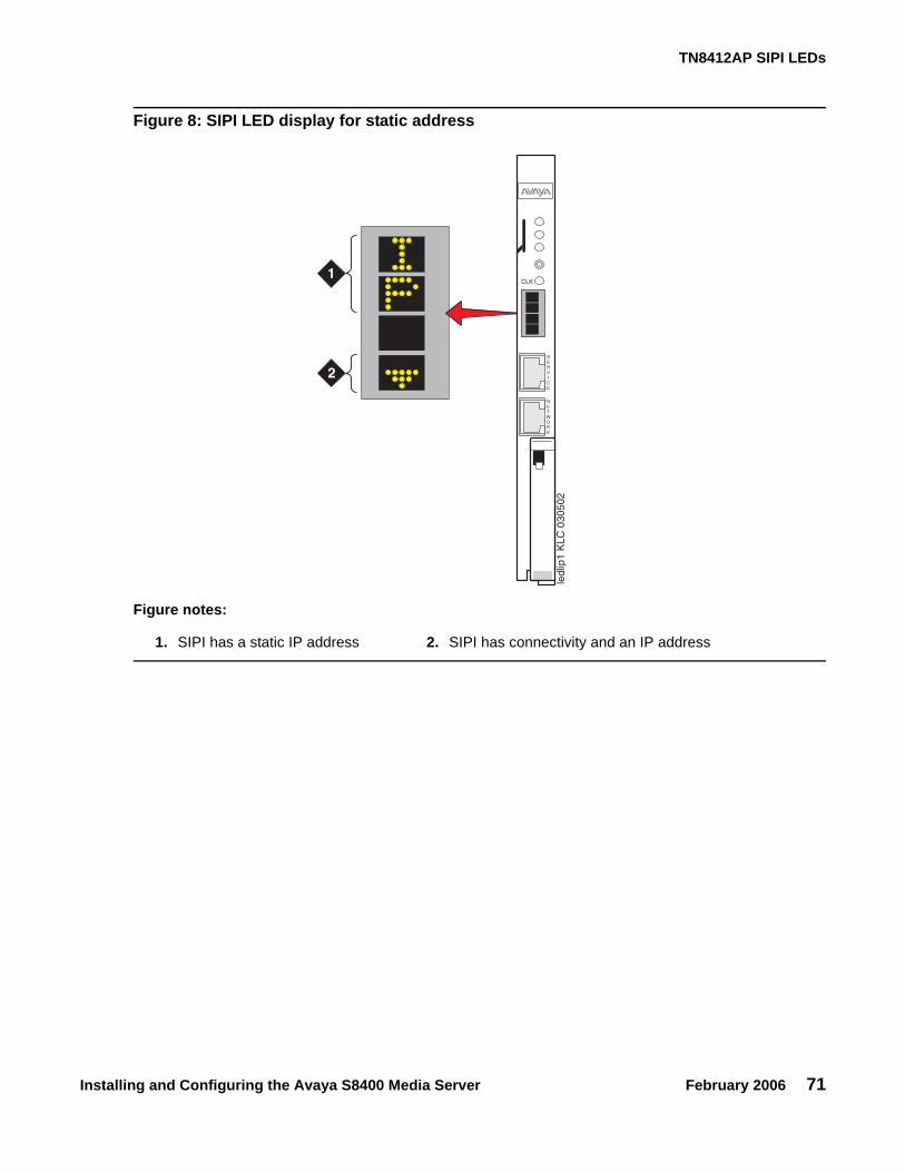
TN8412AP SIPI LEDs
Installing and Configuring the Avaya S8400 Media Server February 2006 71
Figure 8: SIPI LED display for static address
Figure notes:
1. SIPI has a static IP address 2. SIPI has connectivity and an IP address
ledl
ip1
KLC
030
502
1
2
CLK
SERVICE
NETWORK

Chapter 8: Installation verification
72 Installing and Configuring the Avaya S8400 Media Server February 2006

Installing and Configuring the Avaya S8400 Media Server February 2006 73
Appendix A: Media server access
Use a personal computer or services laptop computer equipped with a network interface card (NIC), a terminal emulation program, and a Web browser to access a media server for initial configuration, aftermarket additions, and continuing maintenance.
Access the media server:
● directly (recommended method)
● remotely over the customer’s network (recommended method)
● remotely over a modem (Avaya maintenance access only)
Steps to access a media server include:
● Connecting to the media server directly on page 75
● Connecting to the media server remotely over the network on page 76
● Connecting to the media server remotely over a modem on page 77
● Logins for Avaya technicians and Business Partners on page 79
● Configuring the network for Windows 2000/XP on page 80
Accessing the server’s command line interface with SSH The procedure described in this section shows how to log into the media server from a services laptop using SSH. To use this procedure with a cable connection from the laptop to the services port, you must configure the laptop for the network connection.
To use SSH, a third-party SSH client must be installed on your computer. PuTTY is one such client available for download from http://www.putty.nl/download.html. The following procedure describes, as an example of SSH access, how to log into the server command line with PuTTY.
Note:Note: A version of PuTTY that is defaulted for SSH server access is available for Avaya
services personnel only. In this version, some values below have already been pre-selected.
Note:Note: While a variety of Avaya products support access using SSH, Avaya does not
provide support for third-party clients used for SSH access. Any problems with an SSH client, including PuTTY, are the responsibility of the user or the SSH client vendor.
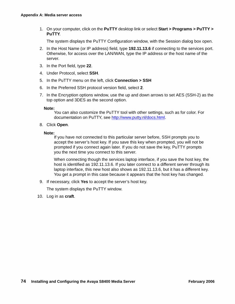
Appendix A: Media server access
74 Installing and Configuring the Avaya S8400 Media Server February 2006
1. On your computer, click on the PuTTY desktop link or select Start > Programs > PuTTY > PuTTY.
The system displays the PuTTY Configuration window, with the Session dialog box open.
2. In the Host Name (or IP address) field, type 192.11.13.6 if connecting to the services port. Otherwise, for access over the LAN/WAN, type the IP address or the host name of the server.
3. In the Port field, type 22.
4. Under Protocol, select SSH.
5. In the PuTTY menu on the left, click Connection > SSH6. In the Preferred SSH protocol version field, select 2.
7. In the Encryption options window, use the up and down arrows to set AES (SSH-2) as the top option and 3DES as the second option.
Note:Note: You can also customize the PuTTY tool with other settings, such as for color. For
documentation on PuTTY, see http://www.putty.nl/docs.html.
8. Click Open.
Note:Note: If you have not connected to this particular server before, SSH prompts you to
accept the server’s host key. If you save this key when prompted, you will not be prompted if you connect again later. If you do not save the key, PuTTY prompts you the next time you connect to this server.
When connecting though the services laptop interface, if you save the host key, the host is identified as 192.11.13.6. If you later connect to a different server through its laptop interface, this new host also shows as 192.11.13.6, but it has a different key. You get a prompt in this case because it appears that the host key has changed.
9. If necessary, click Yes to accept the server’s host key.
The system displays the PuTTY window.
10. Log in as craft.

Connecting to the media server directly
Installing and Configuring the Avaya S8400 Media Server February 2006 75
Connecting to the media server directly To access the media server directly, use a computer with the following minimum specifications:
● Windows 2000/XP operating system
● 32-MB RAM
● 40-MB available disk space
● RS-232 port connector
● Network interface card (NIC) with a 10/100BaseT Ethernet interface
● 10/100 BaseT Ethernet, category 5 (or better), crossover cable with an RJ45 connector on each end (MDI to MDI-X)
● CD-ROM drive
1. Plug one end of the CAT5 cable into the services access port on the media server faceplate.
See Services laptop computer connected directly to the S8400 Media Server on page 76.
2. Plug one end of the CAT5 cable into the NIC on your computer. Use a NIC adapter if necessary.
3. Configure your network connection
● IP address: 192.11.13.5
● Subnet mask: 255.255.255.252
For specific information, see Configuring the network for Windows 2000/XP on page 80.
Once connected, use a terminal emulation program or a Web browser to administer the media server.

Appendix A: Media server access
76 Installing and Configuring the Avaya S8400 Media Server February 2006
Figure 9: Services laptop computer connected directly to the S8400 Media Server
Connecting to the media server remotely over the network You can use any computer to connect to the media server through a LAN. The security settings on the LAN must allow remote access.
1. Open a Web browser or a terminal emulation application.
2. In the address field, enter the IP address or DNS host name assigned to the media server you want to access.
Figure notes:
1. Services laptop2. Network interface card (NIC)
3. NIC adapter cable (if necessary)4. Black CAT5 crossover cable
7003
2760
4
AVA
YA04
J247
7015
75H
V0
TN84
00A
Pcadl8400 LAO 113005
1
2
3
4

Connecting to the media server remotely over a modem
Installing and Configuring the Avaya S8400 Media Server February 2006 77
Connecting to the media server remotely over a modem Note:
Note: Remote access over a modem is for Avaya services support access only and not for routine administration. Because the media server uses the same modem line to report alarms, it cannot report new alarms while the line is in use.
You can access the media server through an analog modem. The remote connection requires a minimum data speed of 33.5 kilobits per second.
1. Launch the dial-up connection program, which varies depending on your operating system. Generally, you can access the program through My Computer or Control Panel folders. See your computer’s help system for specific information.
2. Double-click Make New Connection to open the New Connection wizard.
3. Within the wizard, depending on your operating system, you may be asked to:
● Assign a name to the connection.
● Select dial-up to the network for the network connection type.
● Select the modem you will be using for the dial-up connection.
● Enter the appropriate telephone number to access the active server. See the completed job aid titled Electronic Preinstallation Worksheet for the customer-supplied telephone number(s).
● Under Advanced, select PPP and log on manually. You may have to type in a user name and password, depending on whether or not the media server you are dialing into has a non-null CHAP secret key. Use craft (ignore the password field).
4. Click the connection name or icon, if created. Wait for connection.
5. When prompted, enter your remote access login name and password.
6. When the Start PPP now message appears, click Done. When you see the Connection Complete dialog box, your computer is connected to the media server.
7. To open a Telnet session, click Start > Run to open the Run dialog box.
8. In the Run dialog box, type telnet IPaddress and click OK, where IPaddress is the address of the active media server.

Appendix A: Media server access
78 Installing and Configuring the Avaya S8400 Media Server February 2006
Accessing the Maintenance Web Interface You can administer the media server through the Maintenance Web Interface. Access the Maintenance Web Interface when connected:
● over the customer’s network, using MS Internet Explorer 5.5 or 6.0.
● directly to the services port on the media server (see Services laptop computer connected directly to the S8400 Media Server on page 76)
To access the Maintenance Web Interface, you must first bypass any proxy servers.
1. In Internet Explorer 5.5 or 6.0, Click Tools > Internet Options.
2. Select the Connection tab.
3. In the LAN Settings box (lower righthand), click Advanced.
4. In the Exceptions box after the last entry, type 192.11.13.65. Click OK, then OK, then OK again to close the dialog boxes.
6. Open the MS Internet Explorer Web browser to access the Maintenance Web Interface.
● If connected directly, in the Address field, type 192.11.13.6.
● If connected remotely through a modem, in the Address field, type in the IP address or DNS host name of the media server.
7. When prompted, log in.
Using the SAT command line prompt Use a direct connection to Communication Manager or a remote Secure Shell (SSH) or Telnet session to access the SAT (System Administration Terminal) command line prompt.
SSH: To open a SSH session.
See Accessing the server’s command line interface with SSH on page 73
Telnet: To open a Telnet window session.
1. Click Start > Run to open the Run dialog box.
● On a direct connection, type telnet 192.11.13.6 and click OK.
● On a remote connection to the media server, type in the IP address of the media server.
2. Login at the prompt.

Logins for Avaya technicians and Business Partners
Installing and Configuring the Avaya S8400 Media Server February 2006 79
Terminal Emulation: To use a command line interface in a terminal emulation window, open your terminal emulation application. Configure the terminal emulation program port settings as follows:
● 115200 baud
● No parity
● 8 data bits
● 1 stop bit
● No flow control
Note:Note: Avaya Native Configuration Manager, Avaya Terminal Emulation, and
HyperTerminal are the only terminal emulation programs supported.
Logins for Avaya technicians and Business PartnersAvaya field technicians and Business Partners must use a services login such as craft or dadmin to perform initial configuration and upgrades. An Avaya field technician can use a unique password assigned to the customer’s system.
After the Avaya authentication file is installed, Avaya Communication Manager has a password for the craft login that is unique to the customer’s system and available when connected directly to the media server. Log in as craft and use this password to bypass the ASG challenge and response. Every other means of craft access requires an ASG challenge and response. The revised password is recorded by RFA and is obtained from ASG Conversant at 1-800-248-1234 or 1-720-444-5557.
Customers can set up their own logins for accessing Avaya’s media servers. See the Avaya Communication Manager Basic Administration Quick Reference (03-300363) for specific information. You must have superuser permission to create or change logins and passwords.
Note:Note: Do not start login IDs with a number.

Appendix A: Media server access
80 Installing and Configuring the Avaya S8400 Media Server February 2006
Configuring the network for Windows 2000/XP
! Important:Important: Write down the original settings in case you need to change them back.
To configure the network for Windows 2000/XP:
1. On your computer desktop, right-click My Network Places and left-click Properties to display the Network Connections window.
Windows 2000/XP should automatically detect the Ethernet card in your system and create a LAN connection for you. More than one connection may appear.
2. Right-click on the correct Local Area Connection and left-click Properties to display the Local Area Connection Properties dialog box.
3. Select Internet Protocol (TCP/IP).4. Click Properties to display the Internet Protocol (TCP/IP) Properties dialog box.
5. On the General tab, select Use the following IP address.
6. Make a note of any IP addresses or other entries that you have to clear. You may need to restore them later to connect to another network
Enter the following:
● IP address: 192.11.13.5
● Subnet mask: 255.255.255.252
7. Select Use the following DNS server addresses.
The entries for Preferred DNS server and Alternate DNS server should both be blank.
8. Click Advanced at the bottom of the dialog box to display the Advanced TCP/IP Settings dialog box.
9. Click the DNS tab.
Ensure no DNS server is administered. The address field should be blank.
10. Click OK, OK, and Close to close all the windows.

Setting browser options for Internet Explorer 6.0.
Installing and Configuring the Avaya S8400 Media Server February 2006 81
Setting browser options for Internet Explorer 6.0.A connection session to a media server tends to time out when connected through a proxy server. Add the media servers’ host names or IP addresses to the list of host names and IP addresses to avoid having the media server time out during a session.
To set browser options for Internet Explorer 6.0:
1. In Internet Explorer 6.0, click Tools > Internet Options.
2. Select the Connection tab.
3. Click on LAN settings, then Advanced.
4. In the Do not use proxy server for addresses beginning with field, type in the IP address for each media server you intend to access remotely.
If the IP addresses have the first or first and second octets the same, you can shorten the addresses to xxx.xxx.* (example, 135.9.*).
5. Click OK, then OK, then OK to close all the dialog boxes.

Appendix A: Media server access
82 Installing and Configuring the Avaya S8400 Media Server February 2006

Installing and Configuring the Avaya S8400 Media Server February 2006 83
Appendix B: Installation troubleshooting
This section provides some simple strategies for troubleshooting an installation of a media server. It focuses on possible problems when
● Troubleshooting media server hardware installation on page 83
● Troubleshooting configuring the media server hardware on page 84
● Troubleshooting the installation of license files and Avaya authentication files on page 86
Troubleshooting media server hardware installation.
Troubleshooting media server hardware installation
Problem Possible solution
No power to the UPS
● Make sure the UPS is plugged into the outlet.● Make sure the outlet has power.● See the user guide that comes with UPS for other solutions.
No power to the media server
● Make sure the circuit pack is seated.● Make sure the media gateway is plugged into the UPS.● Make sure the UPS has power.
SIPI LEDs flash ● Make sure it is in the correct slot: (slot 1 for G650 Media Gateway, slot 2 for G600 Media Gateway, Tone-Clock slot for all others).
● Ping SIPI from server.● Ping server from SIPI (it is connected to the Services port on the
SIPI).
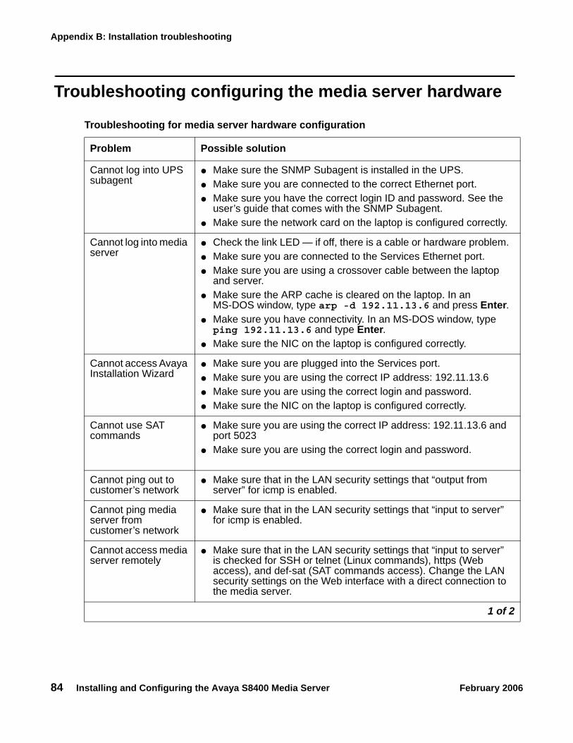
Appendix B: Installation troubleshooting
84 Installing and Configuring the Avaya S8400 Media Server February 2006
Troubleshooting configuring the media server hardware
Troubleshooting for media server hardware configuration
Problem Possible solution
Cannot log into UPS subagent
● Make sure the SNMP Subagent is installed in the UPS.● Make sure you are connected to the correct Ethernet port.● Make sure you have the correct login ID and password. See the
user’s guide that comes with the SNMP Subagent. ● Make sure the network card on the laptop is configured correctly.
Cannot log into media server
● Check the link LED — if off, there is a cable or hardware problem.● Make sure you are connected to the Services Ethernet port.● Make sure you are using a crossover cable between the laptop
and server.● Make sure the ARP cache is cleared on the laptop. In an
MS-DOS window, type arp -d 192.11.13.6 and press Enter.● Make sure you have connectivity. In an MS-DOS window, type ping 192.11.13.6 and type Enter.
● Make sure the NIC on the laptop is configured correctly.
Cannot access Avaya Installation Wizard
● Make sure you are plugged into the Services port.● Make sure you are using the correct IP address: 192.11.13.6 ● Make sure you are using the correct login and password.● Make sure the NIC on the laptop is configured correctly.
Cannot use SAT commands
● Make sure you are using the correct IP address: 192.11.13.6 and port 5023
● Make sure you are using the correct login and password.
Cannot ping out to customer’s network
● Make sure that in the LAN security settings that “output from server” for icmp is enabled.
Cannot ping media server from customer’s network
● Make sure that in the LAN security settings that “input to server” for icmp is enabled.
Cannot access media server remotely
● Make sure that in the LAN security settings that “input to server” is checked for SSH or telnet (Linux commands), https (Web access), and def-sat (SAT commands access). Change the LAN security settings on the Web interface with a direct connection to the media server.
1 of 2

Troubleshooting configuring the media server hardware
Installing and Configuring the Avaya S8400 Media Server February 2006 85
LED display on SIPI is flashing
● SIPI LED has not had an IP address assigned to it (static IP addressing)
Cannot access SIPI for static addressing
● Make sure you are plugged into the Services (top) port on the SIPI.
● Make sure the ARP cache is cleared on the laptop. In an MS-DOS command window, type arp -d 192.11.13.6 and press Enter.
No “V” on SIPI LED ● SIPI is not connected to Ethernet switch or network. Connectcrossover cable between the RJ45 SIPI adapter and Eth-A on the S8400 adapter, or, connect cable to bottom port on faceplate and to the Ethernet switch or the customer’s network.
“V” on SIPI LED is not filled in
● SIPI does not have an IP address assigned to it.● SIPI has not been administered.
Get alarm when first connect to SIPI
● SIPI does not have current firmware. Upgrade firmware.
Troubleshooting for media server hardware configuration (continued)
Problem Possible solution
2 of 2

Appendix B: Installation troubleshooting
86 Installing and Configuring the Avaya S8400 Media Server February 2006
Troubleshooting the installation of license files and Avaya authentication files
Troubleshooting the installation of license files and Avaya authentication files
Problem Possible solution
Cannot get files from RFA site ● Provide the correct SAP number.● Provide the serial number for the SIPI
License file does not install ● Make sure there are not two license files on the server. If so, delete one of them.
● May have corrupt file. Download file again from RFA site.
● Upload using binary mode.
Media server is in no license mode
● Normal situation when license file is first installed because it cannot see the SIPI; it does not have IP address yet.
● After 30 minutes, license has not located SIPI. In a SAT session, type reset system 1 and press Enter to reset the 30-minute clock.
Cannot use administration commands
● May be in No License Mode because 30-minute timer has lapsed. In a SAT session, type reset system 1 and press Enter to reset the 30-minute clock.
ASG does not work ● Re-install Avaya authentication files.

Installing and Configuring the Avaya S8400 Media Server February 2006 87
Index
Index
Aaccess media server
directly . . . . . . . . . . . . . . . . . . . . . 75remotely over modem . . . . . . . . . . . . . . 77remotely over network . . . . . . . . . . . . . 76
accessing Maintenance Web Interface . . . . . . . 78accessing the media server. . . . . . . . . . . . . 30add
IP interface information . . . . . . . . . . . . . 46media gateways . . . . . . . . . . . . . . . . 44
AIW. See Avaya Installation Wizardalarm activation level
setting . . . . . . . . . . . . . . . . . . . . . 47alarms
enabling to INADS via SNMP . . . . . . . . . . 62setting selected traps . . . . . . . . . . . . . . 28viewing. . . . . . . . . . . . . . . . . . . . . 60
ARP cache, clearing . . . . . . . . . . . . . . . . 29Avaya Installation Wizard, using . . . . . . . . . . 38
Cclearing ARP cache . . . . . . . . . . . . . . . . 29command line interface. . . . . . . . . . . . . . . 78Communication Manager
installing software. . . . . . . . . . . . . . . . 29configure
media server . . . . . . . . . . . . . . . . .35, 43modem. . . . . . . . . . . . . . . . . . . . . 41MPC . . . . . . . . . . . . . . . . . . . . . . 39UPS . . . . . . . . . . . . . . . . . . . . . . 25
connect to customer network . . . . . . . . . . . . 14connection to LAN, verifying . . . . . . . . . . . . 40customer network, connecting to . . . . . . . . . . 14
Ddate and time, verifying. . . . . . . . . . . . . . . 60daylight savings rules
location . . . . . . . . . . . . . . . . . . . . 59setting . . . . . . . . . . . . . . . . . . . . . 58
direct access to media server . . . . . . . . . . . . 75downloading files . . . . . . . . . . . . . . . . . 10
Ffaceplate
S8400 interfaces . . . . . . . . . . . . . . . . 66TN8400AP circuit pack . . . . . . . . . . . . . 65TN8412AP circuit pack . . . . . . . . . . . . . 69
firewall settings . . . . . . . . . . . . . . . . . . . 40
IIA 770 installation. . . . . . . . . . . . . . . . . . 33inputting translations . . . . . . . . . . . . . . . . 44installation
process, high-level overview . . . . . . . . . . . 23troubleshooting . . . . . . . . . . . . . . . . . 83using the Wizard . . . . . . . . . . . . . . . . 38
installingCommunication Manager software . . . . . . . . 32MPC firmware. . . . . . . . . . . . . . . . . . 39translation file . . . . . . . . . . . . . . . . . . 47
IP addressset static . . . . . . . . . . . . . . . . . . . . 50
IP address, set static . . . . . . . . . . . . . . . . 50IP interface
enabling control . . . . . . . . . . . . . . . . . 55LEDs . . . . . . . . . . . . . . . . . . . . . . 69upgrading firmware version . . . . . . . . . . . 54verify translations . . . . . . . . . . . . . . . . 54
IP interface informationadding to translations . . . . . . . . . . . . . . 46
LLEDs
IP interface . . . . . . . . . . . . . . . . . . . 69S8400 . . . . . . . . . . . . . . . . . . . . . 67UPS . . . . . . . . . . . . . . . . . . . . . . 68
license file, testing . . . . . . . . . . . . . . . . . 64license, verifying status . . . . . . . . . . . . . . . 55location
daylight savings rules . . . . . . . . . . . . . . 59setting . . . . . . . . . . . . . . . . . . . . . 59
MMaintenance Processor Complex. See MPCMaintenance Web Interface, accessing . . . . . . . 78

88 Installing and Configuring the Avaya S8400 Media Server February 2006
Index
media gateways, adding . . . . . . . . . . . . . . 44media server
accessing . . . . . . . . . . . . . . . . . . . 30configuring . . . . . . . . . . . . . . . . . .35, 43powering up . . . . . . . . . . . . . . . . . . 30verify connectivity. . . . . . . . . . . . . . . . 54verifying LAN connection . . . . . . . . . . . . 40
modemaccess to media server . . . . . . . . . . . . . 77configuring . . . . . . . . . . . . . . . . . . . 41connect to media server. . . . . . . . . . . . . 20
MPC, configuring . . . . . . . . . . . . . . . . . 39
Nnetwork time server (NTP), enabling . . . . . . . . 37
Ooverview of installation process . . . . . . . . . . . 23
Ppowering up media server . . . . . . . . . . . . . 30pre-installation
before going to the installation site . . . . . . . . . 9Processor Ethernet . . . . . . . . . . . . . . . . 21PuTTY, SSH client . . . . . . . . . . . . . . . . . 73
Rremote access to media server
over modem . . . . . . . . . . . . . . . . . . 77over network . . . . . . . . . . . . . . . . . . 76
Ssaving translations . . . . . . . . . . . . . . . .44, 47set
alarm activation level . . . . . . . . . . . . . . 47daylight savings rules . . . . . . . . . . . . . . 58location . . . . . . . . . . . . . . . . . . . . 59selected traps (alarming) . . . . . . . . . . . . 28static IP address . . . . . . . . . . . . . . . . 50
set static IP address . . . . . . . . . . . . . . . . 50SIPI
programming a static address . . . . . . . . . . 50software, installing Communication Manager . . . . 32SSH
about . . . . . . . . . . . . . . . . . . . . . 22access with. . . . . . . . . . . . . . . . . . . 73
static IP addressingsetting . . . . . . . . . . . . . . . . . . . . . 50
static IP addressing, setting. . . . . . . . . . . . . 50
TTelnet
configuring for Win2000/XP . . . . . . . . . . . 31terminal emulation . . . . . . . . . . . . . . . . . 78
starting . . . . . . . . . . . . . . . . . . . . . 44testing
license file . . . . . . . . . . . . . . . . . . . 64media server installation . . . . . . . . . . . . . 63TN2312BP . . . . . . . . . . . . . . . . . . . 64
TN2312BP, testing . . . . . . . . . . . . . . . . . 64TN8400AP
faceplate . . . . . . . . . . . . . . . . . . . . 65LEDs . . . . . . . . . . . . . . . . . . . . 65, 67
TN8412APfaceplate . . . . . . . . . . . . . . . . . . . . 69LEDs . . . . . . . . . . . . . . . . . . . . . . 69
translation fileinstalling . . . . . . . . . . . . . . . . . . . . 47
translationsinputting . . . . . . . . . . . . . . . . . . . . 44IP interface . . . . . . . . . . . . . . . . . . . 43saving . . . . . . . . . . . . . . . . . . . 44, 47verifying . . . . . . . . . . . . . . . . . . . . 57
troubleshooting, media server installation . . . . . . 83
Uupgrading
IP interface firmware version . . . . . . . . . . . 54UPS
LEDs . . . . . . . . . . . . . . . . . . . . . . 68security alert . . . . . . . . . . . . . . . . . . 25SNMP module . . . . . . . . . . . . . . . . . 25
UPS, configuring . . . . . . . . . . . . . . . . . . 25using this documentation . . . . . . . . . . . . . . . 8
Vverify
connectivity to media servers. . . . . . . . . . . 54date and time . . . . . . . . . . . . . . . . . . 60IP interface translated . . . . . . . . . . . . . . 54license status . . . . . . . . . . . . . . . . . . 55media server connection to LAN . . . . . . . . . 40translations . . . . . . . . . . . . . . . . . . . 57
view alarms . . . . . . . . . . . . . . . . . . . . 60
WWizard, installation . . . . . . . . . . . . . . . . . 38