Embed Size (px)
Citation preview
Configuring Link Aggregation, MLT, andSMLT on Avaya Virtual Services Platform9000
Release 4.0NN46250-503
Issue 06.02December 2014
© 2014 Avaya Inc.
All Rights Reserved.
NoticeWhile reasonable efforts have been made to ensure that theinformation in this document is complete and accurate at the time ofprinting, Avaya assumes no liability for any errors. Avaya reservesthe right to make changes and corrections to the information in thisdocument without the obligation to notify any person or organizationof such changes.
Documentation disclaimer“Documentation” means information published by Avaya in varyingmediums which may include product information, operatinginstructions and performance specifications that Avaya may generallymake available to users of its products and Hosted Services.Documentation does not include marketing materials. Avaya shall notbe responsible for any modifications, additions, or deletions to theoriginal published version of documentation unless suchmodifications, additions, or deletions were performed by Avaya. EndUser agrees to indemnify and hold harmless Avaya, Avaya's agents,servants and employees against all claims, lawsuits, demands andjudgments arising out of, or in connection with, subsequentmodifications, additions or deletions to this documentation, to theextent made by End User.
Link disclaimerAvaya is not responsible for the contents or reliability of any linkedwebsites referenced within this site or documentation provided byAvaya. Avaya is not responsible for the accuracy of any information,statement or content provided on these sites and does notnecessarily endorse the products, services, or information describedor offered within them. Avaya does not guarantee that these links willwork all the time and has no control over the availability of the linkedpages.
WarrantyAvaya provides a limited warranty on Avaya hardware and software.Refer to your sales agreement to establish the terms of the limitedwarranty. In addition, Avaya’s standard warranty language, as well asinformation regarding support for this product while under warranty isavailable to Avaya customers and other parties through the AvayaSupport website: http://support.avaya.com or such successor site asdesignated by Avaya. Please note that if You acquired the product(s)from an authorized Avaya Channel Partner outside of the UnitedStates and Canada, the warranty is provided to You by said AvayaChannel Partner and not by Avaya.
LicensesTHE SOFTWARE LICENSE TERMS AVAILABLE ON THE AVAYAWEBSITE, HTTP://SUPPORT.AVAYA.COM/LICENSEINFO ORSUCH SUCCESSOR SITE AS DESIGNATED BY AVAYA, AREAPPLICABLE TO ANYONE WHO DOWNLOADS, USES AND/ORINSTALLS AVAYA SOFTWARE, PURCHASED FROM AVAYA INC.,ANY AVAYA AFFILIATE, OR AN AVAYA CHANNEL PARTNER (ASAPPLICABLE) UNDER A COMMERCIAL AGREEMENT WITHAVAYA OR AN AVAYA CHANNEL PARTNER. UNLESSOTHERWISE AGREED TO BY AVAYA IN WRITING, AVAYA DOESNOT EXTEND THIS LICENSE IF THE SOFTWARE WASOBTAINED FROM ANYONE OTHER THAN AVAYA, AN AVAYAAFFILIATE OR AN AVAYA CHANNEL PARTNER; AVAYARESERVES THE RIGHT TO TAKE LEGAL ACTION AGAINST YOUAND ANYONE ELSE USING OR SELLING THE SOFTWAREWITHOUT A LICENSE. BY INSTALLING, DOWNLOADING ORUSING THE SOFTWARE, OR AUTHORIZING OTHERS TO DO SO,YOU, ON BEHALF OF YOURSELF AND THE ENTITY FOR WHOMYOU ARE INSTALLING, DOWNLOADING OR USING THESOFTWARE (HEREINAFTER REFERRED TOINTERCHANGEABLY AS “YOU” AND “END USER”), AGREE TOTHESE TERMS AND CONDITIONS AND CREATE A BINDINGCONTRACT BETWEEN YOU AND AVAYA INC. OR THEAPPLICABLE AVAYA AFFILIATE (“AVAYA”).
Avaya grants You a license within the scope of the license typesdescribed below, with the exception of Heritage Nortel Software, forwhich the scope of the license is detailed below. Where the orderdocumentation does not expressly identify a license type, theapplicable license will be a Designated System License. The
applicable number of licenses and units of capacity for which thelicense is granted will be one (1), unless a different number oflicenses or units of capacity is specified in the documentation or othermaterials available to You. “Software” means computer programs inobject code, provided by Avaya or an Avaya Channel Partner,whether as stand-alone products, pre-installed on hardware products,and any upgrades, updates, patches, bug fixes, or modified versionsthereto. “Designated Processor” means a single stand-alonecomputing device. “Server” means a Designated Processor thathosts a software application to be accessed by multiple users.“Instance” means a single copy of the Software executing at aparticular time: (i) on one physical machine; or (ii) on one deployedsoftware virtual machine (“VM”) or similar deployment.
License typesDesignated System(s) License (DS). End User may install and useeach copy or an Instance of the Software only on a number ofDesignated Processors up to the number indicated in the order.Avaya may require the Designated Processor(s) to be identified inthe order by type, serial number, feature key, Instance, location orother specific designation, or to be provided by End User to Avayathrough electronic means established by Avaya specifically for thispurpose.
Heritage Nortel Software“Heritage Nortel Software” means the software that was acquired byAvaya as part of its purchase of the Nortel Enterprise SolutionsBusiness in December 2009. The Heritage Nortel Software currentlyavailable for license from Avaya is the software contained within thelist of Heritage Nortel Products located at http://support.avaya.com/LicenseInfo under the link “Heritage Nortel Products” or suchsuccessor site as designated by Avaya. For Heritage NortelSoftware, Avaya grants You a license to use Heritage NortelSoftware provided hereunder solely to the extent of the authorizedactivation or authorized usage level, solely for the purpose specifiedin the Documentation, and solely as embedded in, for execution on,or for communication with Avaya equipment. Charges for HeritageNortel Software may be based on extent of activation or useauthorized as specified in an order or invoice.
CopyrightExcept where expressly stated otherwise, no use should be made ofmaterials on this site, the Documentation, Software, Hosted Service,or hardware provided by Avaya. All content on this site, thedocumentation, Hosted Service, and the product provided by Avayaincluding the selection, arrangement and design of the content isowned either by Avaya or its licensors and is protected by copyrightand other intellectual property laws including the sui generis rightsrelating to the protection of databases. You may not modify, copy,reproduce, republish, upload, post, transmit or distribute in any wayany content, in whole or in part, including any code and softwareunless expressly authorized by Avaya. Unauthorized reproduction,transmission, dissemination, storage, and or use without the expresswritten consent of Avaya can be a criminal, as well as a civil offenseunder the applicable law.
Third Party Components“Third Party Components” mean certain software programs orportions thereof included in the Software or Hosted Service maycontain software (including open source software) distributed underthird party agreements (“Third Party Components”), which containterms regarding the rights to use certain portions of the Software(“Third Party Terms”). As required, information regarding distributedLinux OS source code (for those products that have distributed LinuxOS source code) and identifying the copyright holders of the ThirdParty Components and the Third Party Terms that apply is availablein the products, Documentation or on Avaya’s website at: http://support.avaya.com/Copyright or such successor site as designatedby Avaya. You agree to the Third Party Terms for any such ThirdParty Components.
Preventing Toll Fraud“Toll Fraud” is the unauthorized use of your telecommunicationssystem by an unauthorized party (for example, a person who is not acorporate employee, agent, subcontractor, or is not working on yourcompany's behalf). Be aware that there can be a risk of Toll Fraudassociated with your system and that, if Toll Fraud occurs, it can
result in substantial additional charges for your telecommunicationsservices.
Avaya Toll Fraud interventionIf You suspect that You are being victimized by Toll Fraud and Youneed technical assistance or support, call Technical Service CenterToll Fraud Intervention Hotline at +1-800-643-2353 for the UnitedStates and Canada. For additional support telephone numbers, seethe Avaya Support website: http://support.avaya.com or suchsuccessor site as designated by Avaya. Suspected securityvulnerabilities with Avaya products should be reported to Avaya bysending mail to: [email protected].
Downloading DocumentationFor the most current versions of Documentation, see the AvayaSupport website: http://support.avaya.com, or such successor site asdesignated by Avaya.
Contact Avaya SupportSee the Avaya Support website: http://support.avaya.com for productor Hosted Service notices and articles, or to report a problem withyour Avaya product or Hosted Service. For a list of support telephonenumbers and contact addresses, go to the Avaya Support website: http://support.avaya.com (or such successor site as designated byAvaya), scroll to the bottom of the page, and select Contact AvayaSupport.
TrademarksThe trademarks, logos and service marks (“Marks”) displayed in thissite, the Documentation, Hosted Service(s), and product(s) providedby Avaya are the registered or unregistered Marks of Avaya, itsaffiliates, or other third parties. Users are not permitted to use suchMarks without prior written consent from Avaya or such third partywhich may own the Mark. Nothing contained in this site, theDocumentation, Hosted Service(s) and product(s) should beconstrued as granting, by implication, estoppel, or otherwise, anylicense or right in and to the Marks without the express writtenpermission of Avaya or the applicable third party.
Avaya is a registered trademark of Avaya Inc.
All non-Avaya trademarks are the property of their respective owners.Linux® is the registered trademark of Linus Torvalds in the U.S. andother countries.
Contents
Chapter 1: Introduction............................................................................................................ 6Purpose.................................................................................................................................. 6Related resources................................................................................................................... 6
Documentation.................................................................................................................. 6Training............................................................................................................................ 6Viewing Avaya Mentor videos............................................................................................. 6
Support.................................................................................................................................. 7Searching a documentation collection................................................................................. 7
Chapter 2: New in this release................................................................................................. 9Features................................................................................................................................. 9Other changes........................................................................................................................ 9
Chapter 3: Link Aggregation Control Protocol.................................................................... 10Link aggregation overview...................................................................................................... 10LACP configuration considerations......................................................................................... 11LACP configuration using ACLI.............................................................................................. 12
Configuring global LACP parameters................................................................................ 13Configuring LACP on a port.............................................................................................. 14Viewing LACP configuration information............................................................................ 17
LACP configuration using EDM.............................................................................................. 20Configuring global LACP parameters................................................................................ 20Configuring LACP parameters.......................................................................................... 22Configuring LACP on a port.............................................................................................. 23
Chapter 4: MultiLink Trunking and Split MultiLink Trunking.............................................. 29Link aggregation overview...................................................................................................... 29MultiLink Trunking................................................................................................................. 30MultiLink Trunking with LACP................................................................................................. 33Split MultiLink Trunking.......................................................................................................... 35MLT and SMLT configuration considerations........................................................................... 43MLT and SMLT link aggregation configuration using the ACLI................................................... 46
Configuring an MLT......................................................................................................... 46Adding ports to an MLT LAG............................................................................................ 48Removing ports from an MLT LAG.................................................................................... 48Configuring LACP on an MLT........................................................................................... 49Creating an SMLT from an existing MLT........................................................................... 50Creating an interswitch trunk............................................................................................ 51Enabling an interswitch trunk............................................................................................ 52Deleting an interswitch trunk............................................................................................. 53Viewing the MLT port calculated by the MLT hash algorithm............................................... 53Viewing information about collision errors.......................................................................... 54
4 Configuring Link Aggregation, MLT, and SMLT on Avaya VSP 9000 December 2014Comments? [email protected]
Viewing information about Ethernet errors......................................................................... 55Viewing all ports configured for SMLT............................................................................... 55
MLT and SMLT link aggregation configuration using EDM........................................................ 56Adding a multilink, interswitch, or LACP trunk.................................................................... 56Adding ports to an MLT.................................................................................................... 59Viewing trunks................................................................................................................ 59Configuring an IST MLT................................................................................................... 60Editing an IST................................................................................................................. 61
MLT configuration examples................................................................................................... 62MultiLink Trunking........................................................................................................... 62MultiLink Trunking with Link Aggregation Control Protocol.................................................. 62
MLT network topology and configuration reference.................................................................. 63Example 1: Switch-to-switch MLT..................................................................................... 64Example 2: Switch-to-server MLT..................................................................................... 64Example 3: Client/Server MLT.......................................................................................... 65
Chapter 5: Virtual Link Aggregation Control Protocol........................................................ 67Virtual Link Aggregation Control Protocol................................................................................ 67VLACP configuration using ACLI............................................................................................ 69
Configuring VLACP on a port........................................................................................... 69Viewing the VLACP port configuration............................................................................... 71Enabling or disabling VLACP globally............................................................................... 72
VLACP configuration using EDM............................................................................................ 72Enabling VLACP globally................................................................................................. 73Configuring VLACP on a port........................................................................................... 73
Glossary................................................................................................................................... 75
Contents
December 2014 Configuring Link Aggregation, MLT, and SMLT on Avaya VSP 9000 5Comments? [email protected]
Chapter 1: Introduction
PurposeThis document contains conceptual and procedural information to help you configure and managelink aggregation and MultiLink Trunking on the Avaya Virtual Services Platform 9000. This documentalso provides instructions for using both Enterprise Device Manager (EDM) and Avaya CommandLine Interface (ACLI).
Related resources
DocumentationSee Documentation Reference for Avaya Virtual Services Platform 9000, NN46250-100 for a list ofthe documentation for this product.
TrainingOngoing product training is available. For more information or to register, you can access thewebsite at http://avaya-learning.com/.
Course code Course title4D00010E Knowledge Access: ACIS - Avaya ERS 8000 and
VSP 9000 Implementation5D00040E Knowledge Access: ACSS - Avaya VSP 9000
Support
Viewing Avaya Mentor videosAvaya Mentor videos provide technical content on how to install, configure, and troubleshoot Avayaproducts.
6 Configuring Link Aggregation, MLT, and SMLT on Avaya VSP 9000 December 2014Comments? [email protected]

About this taskVideos are available on the Avaya Support website, listed under the video document type, and onthe Avaya-run channel on YouTube.
Procedure• To find videos on the Avaya Support website, go to http://support.avaya.com and perform one
of the following actions:
- In Search, type Avaya Mentor Videos to see a list of the available videos.
- In Search, type the product name. On the Search Results page, select Video in theContent Type column on the left.
• To find the Avaya Mentor videos on YouTube, go to www.youtube.com/AvayaMentor andperform one of the following actions:
- Enter a key word or key words in the Search Channel to search for a specific product ortopic.
- Scroll down Playlists, and click the name of a topic to see the available list of videos postedon the website.
Note:
Videos are not available for all products.
SupportGo to the Avaya Support website at http://support.avaya.com for the most up-to-datedocumentation, product notices, and knowledge articles. You can also search for release notes,downloads, and resolutions to issues. Use the online service request system to create a servicerequest. Chat with live agents to get answers to questions, or request an agent to connect you to asupport team if an issue requires additional expertise.
Searching a documentation collectionOn the Avaya Support website, you can download the documentation library for a specific productand software release to perform searches across an entire document collection. For example, youcan perform a single, simultaneous search across the collection to quickly find all occurrences of aparticular feature. Use this procedure to perform an index search of your documentation collection.
Before you begin• Download the documentation collection zip file to your local computer.• You must have Adobe Acrobat or Adobe Reader installed on your computer.
Procedure1. Extract the document collection zip file into a folder.
Support
December 2014 Configuring Link Aggregation, MLT, and SMLT on Avaya VSP 9000 7Comments? [email protected]

2. Navigate to the folder that contains the extracted files and open the file named<product_name_release>.pdx.
3. In the Search dialog box, select the option In the index named<product_name_release>.pdx.
4. Enter a search word or phrase.
5. Select any of the following to narrow your search:
• Whole Words Only
• Case-Sensitive
• Include Bookmarks
• Include Comments
6. Click Search.
The search results show the number of documents and instances found. You can sort thesearch results by Relevance Ranking, Date Modified, Filename, or Location. The default isRelevance Ranking.
Introduction
8 Configuring Link Aggregation, MLT, and SMLT on Avaya VSP 9000 December 2014Comments? [email protected]
Chapter 2: New in this release
The following sections detail what is new in Configuring Link Aggregation, MLT, and SMLT onAvaya Virtual Services Platform 9000, NN46250-503 for Release 4.0.
FeaturesSee the following sections for information about feature changes.
Clarification about LACP configuration changes in a square or full-mesh corenetworkMLT and SMLT configuration considerations on page 43 is updated to reflect the proper tasks tofollow if you need to change the LACP configuration in a square or full-mesh core network, forexample, if you need to change the LACP keys, which must always match. Failure to follow thenecessary tasks can cause a looping scenario in the network.
Update to show mlt command outputRelease 4.0 updates the output for the show mlt <1–512> command. For more information, see Configuring an MLT on page 46.
Other changesSee the following section about changes that are not feature-related.
Document title changeIn Release 4.0, the title of this document changed from Avaya Virtual Services Platform 9000Configuration — Link Aggregation, MLT, and SMLT, NN46250-503 to Configuring Link Aggregation,MLT, and SMLT on Avaya Virtual Services Platform 9000, NN46250-503.
December 2014 Configuring Link Aggregation, MLT, and SMLT on Avaya VSP 9000 9Comments? [email protected]
Chapter 3: Link Aggregation ControlProtocol
This section provides the concepts and procedures you need to configure the Link AggregationControl Protocol (LACP) to dynamically aggregate links as they become available to a trunk group.
Link aggregation overviewLink aggregation provides link level redundancy and increases load sharing. Use Link aggregationto bundle the ports into a port group, which is represented as one logical interface to the MediaAccess Control (MAC) layer.
The Avaya Virtual Services Platform 9000 supports the following types of link aggregation:
• MultiLink Trunking (MLT)—a statically configured link bundling method. MLT is not standardsbased, but it interoperates with static link methods of other vendors. If you aggregate links frommultiple modules together, MLT can provide not only port redundancy, but also moduleredundancy.
• IEEE 802.3ad based link aggregation, through the Link Aggregation Control Protocol (LACP),dynamically aggregates links as they become available to a trunk group. Link AggregationControl Protocol dynamically detects whether links can be aggregated into a link aggregationgroup (LAG) and does so after links become available. Link Aggregation Control Protocol alsoprovides link integrity checking at Layer 2 for all links within the LAG.
Both MLT and IEEE 802.3ad based link aggregation are point-to-point functions.
The Virtual Services Platform 9000 software offers LACP functionality layered with MLT. Thisdocument uses the term MLT with LACP to refer to this functionality.
An Interswitch Trunk (IST) is a special form of aggregate link. ISTs use a link aggregationmechanism such as a Multilink Trunk (MLT) to create a single logical switch out of two physicaldevices. Creating one logical switch allows the devices to share resources, enhance fault tolerance,and create network redundancy.
Split MultiLink Trunking (SMLT) is an option that improves Layer 2 (bridged) resiliency by providingfor the addition of a Virtual Services Platform 9000 failure redundancy with subsecond failover, ontop of all standard MLT link failure protection and flexible bandwidth scaling functionality. Use SMLTto connect a device that supports some form of link aggregation, be it a switch or a server, to two
10 Configuring Link Aggregation, MLT, and SMLT on Avaya VSP 9000 December 2014Comments? [email protected]
distinct separate SMLT endpoints or switches. These SMLT devices form a Switch Cluster and arereferred to as an Interswitch Trunk (IST) Core Switch pair.
You can also use LACP on SMLT configurations. The Virtual Services Platform 9000 providesmodifications to the LACP in SMLT configurations. LACP-capable devices can connect to an SMLTaggregation pair. Avaya recommends that you do not configure LACP on the IST MLT.
Virtual LACP (VLACP) is an Avaya modification that provides end-to-end failure detection. TheVLACP is not a link aggregation protocol; VLACP implements link status control protocol at the portlevel. This mechanism periodically checks the end-to-end health of a point-to-point or end-to-endconnection. You can run VLACP on single ports or on ports that are part of an MLT. Avayarecommends that you do not configure VLACP on LACP-enabled ports. Virtual LACP does notoperate properly with LACP. You can configure VLACP with an SMLT configuration.
LACP configuration considerationsYou can configure priorities, keys, modes, and timers for the LACP.
When you configure LACP on the IST Core Switch pair, you must configure the same LACP smlt-sys-id on each switch in the pair.
LACP priorityYou can configure LACP priority at the system and port level as follows:
• Port priority—determines which ports are aggregated into a LAG that has more than eight portsconfigured to it, as in a standby-port configuration.
• System priority—generates the switch ID after communicating with other systems. For SMLTapplications, use a system priority to determine a master-slave relationship between the SMLTswitches. Avaya recommends that you use the default value. If you need to change it, firstdisable the LACP, and then enable it again after you change the value.
LACP keysYou can use the LACP keys to determine which ports are eligible for link aggregation. The LACPkeys are defined by the ports after you configure the multilink trunk. You can aggregate the portskey that match the MLT key into that multilink trunk.
• Keys do not have to match between two LACP peers.• Keys do not have to match on SMLT core switches if you use LACP with SMLT.
LACP timersYou can customize failover times by changing the LACP timer attributes (fast periodic time, slowperiodic time, and aggregate wait time). Values are set by default to match the IEEE 802.3advalues. If you change the values, they must match on the ports participating in aggregation betweentwo devices.
Changes to LACP timer values at the global level are reflected on all ports. However, you canchange the LACP timer values for each port level. After you change an LACP timer globally, thisvalue is set on all ports. The global timer value overwrites the local port value irrespective of theLACP state. You must configure port values that differ from the global values.
LACP configuration considerations
December 2014 Configuring Link Aggregation, MLT, and SMLT on Avaya VSP 9000 11Comments? [email protected]
Avaya Virtual Services Platform 9000 software uses the following LACP timers:
• fast periodic timer—200 to 20 000 milliseconds (ms); default 1000 ms• slow periodic timer—10 000 to 30 000 ms; default 30000 ms• aggregation-wait timer—200 to 2000; default 2000
You cannot aggregate a link if it does not receive an LACPDU for a period of timeout x slow periodictime = 3 x 30 seconds = 90 seconds. If you use the fast periodic time, the timeout period is 3 x 1000ms = 3 seconds. You must make timer changes to all ports participating in link aggregation and tothe ports on the partnering node.
Configuration changes to the LACP timers are not reflected immediately. Link Aggregation ControlProtocol timers do not reset until the next time you restart LACP globally or on a port. This ensuresconsistency with peer switches.
After you enable LACP on a port, the timer values are set at the port level. You must toggle theLACP status after timer values change. This does not impact existing ports unless you toggle theLACP status on the port.
LACP modesLACP uses two active and passive modes.
• Active mode—ports initiate the aggregation process. Active mode ports aggregate with otheractive mode ports or passive mode ports.
• Passive mode—ports participate in LACP but do not initiate the aggregation process. You mustpartner passive mode ports with active mode ports for aggregation to occur.
Link aggregation scalingThe following table summarizes the number of aggregation groups supported on Virtual ServicesPlatform 9000 modules. For more information about the latest scalability information, see therelease notes included with your switch.
Table 1: Link aggregation scaling for the Virtual Services Platform 9000
Feature NumberAggregation groups
• 802.3ad aggregation groups (LAG)
• multilink trunk groups
512
Maximum number of links (ports) for each MLT group 16
LACP configuration using ACLIThis section describes how to configure and manage link aggregation using the Avaya CommandLine Interface (ACLI), including Link Aggregation Control Protocol (LACP), to increase the linkspeed and redundancy for higher availability.
Link Aggregation Control Protocol
12 Configuring Link Aggregation, MLT, and SMLT on Avaya VSP 9000 December 2014Comments? [email protected]
MultiLink Trunking (MLT) with LACP manages switch ports and port memberships to form a linkaggregation group (LAG). Configure LACP to allow dynamic bundling of physical ports to form asingle logical channel.
You can describe the LACP in terms of link aggregation operations within a single system. You canconfigure a single piece of equipment so it contains more than one system (from the point of view ofthe link aggregation operation).
Before you begin• Changes to LACP made at the global level overrides and resets all port level settings.
Important:After you globally configure the LACP system priority, it applies to all LACP-enabledaggregators and ports. After you enable the LACP on an aggregator or port, it uses theglobal system priority value.
• After you make a timer change, restart the LACP (globally or on the port) so the changes areconsistent across the link.
Important:Configuration changes to LACP timers are not reflected immediately. LACP timers are notreset until the next time LACP is restarted globally or on a port. This action ensuresconsistency with peer switches.
• Virtual Services Platform 9000 does not support standby mode for LACP aggregation groups oflarger than eight ports.
Configuring global LACP parametersConfigure LACP parameters globally. After you configure the LACP system priority globally, itapplies to all LACP-enabled aggregators and ports. After you enable the LACP on an aggregator ora port, it uses the global system priority value.
The new global parameter configuration is in effect after the LACP is restarted globally or on eachport.
About this taskImportant:Changes made at the global level override and reset all port level settings.
Procedure1. Log on to Global Configuration mode:
enableconfigure terminal
2. Change the system priority:
lacp system-priority <0-65535>
LACP configuration using ACLI
December 2014 Configuring Link Aggregation, MLT, and SMLT on Avaya VSP 9000 13Comments? [email protected]
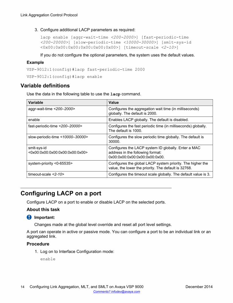
3. Configure additional LACP parameters as required:
lacp enable [aggr-wait-time <200-2000>] [fast-periodic-time<200-20000>] [slow-periodic-time <10000-30000>] [smlt-sys-id<0x00:0x00:0x00:0x00:0x00:0x00>] [timeout-scale <2-10>]If you do not configure the optional parameters, the system uses the default values.
ExampleVSP-9012:1(config)#lacp fast-periodic-time 2000VSP-9012:1(config)#lacp enable
Variable definitionsUse the data in the following table to use the lacp command.
Variable Valueaggr-wait-time <200–2000> Configures the aggregation wait time (in milliseconds)
globally. The default is 2000.enable Enables LACP globally. The default is disabled.fast-periodic-time <200–20000> Configures the fast periodic time (in milliseconds) globally.
The default is 1000.slow-periodic-time <10000–30000> Configures the slow periodic time globally. The default is
30000.smlt-sys-id<0x00:0x00:0x00:0x00:0x00:0x00>
Configures the LACP system ID globally. Enter a MACaddress in the following format:0x00:0x00:0x00:0x00:0x00:0x00.
system-priority <0-65535> Configures the global LACP system priority. The higher thevalue, the lower the priority. The default is 32768.
timeout-scale <2-10> Configures the timeout scale globally. The default value is 3.
Configuring LACP on a portConfigure LACP on a port to enable or disable LACP on the selected ports.
About this taskImportant:Changes made at the global level override and reset all port level settings.
A port can operate in active or passive mode. You can configure a port to be an individual link or anaggregated link.
Procedure1. Log on to Interface Configuration mode:
enable
Link Aggregation Control Protocol
14 Configuring Link Aggregation, MLT, and SMLT on Avaya VSP 9000 December 2014Comments? [email protected]
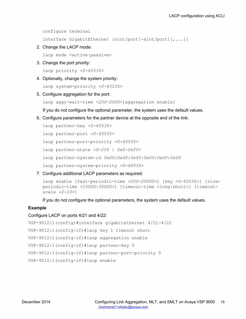
configure terminalinterface GigabitEthernet {slot/port[-slot/port][,...]}
2. Change the LACP mode:
lacp mode <active|passive>3. Change the port priority:
lacp priority <0-65535>4. Optionally, change the system priority:
lacp system-priority <0-65535>5. Configure aggregation for the port:
lacp aggr-wait-time <200-2000>[aggregation enable]If you do not configure the optional parameter, the system uses the default values.
6. Configure parameters for the partner device at the opposite end of the link:
lacp partner-key <0-65535>lacp partner-port <0-65535>lacp partner-port-priority <0-65535>lacp partner-state <0-255 | 0x0-0xff>lacp partner-system-id 0x00:0x00:0x00:0x00:0x00:0x00lacp partner-system-priority <0-65535>
7. Configure additional LACP parameters as required:
lacp enable [fast-periodic-time <200-20000>] [key <0-65535>] [slow-periodic-time <10000-30000>] [timeout-time <long|short>] [timeout-scale <2-10>]If you do not configure the optional parameters, the system uses the default values.
ExampleConfigure LACP on ports 4/21 and 4/22:VSP-9012:1(config)#interface gigabitethernet 4/21–4/22VSP-9012:1(config-if)#lacp key 1 timeout shortVSP-9012:1(config-if)#lacp aggregation enableVSP-9012:1(config-if)#lacp partner-key 0VSP-9012:1(config-if)#lacp partner-port-priority 0VSP-9012:1(config-if)#lacp enable
LACP configuration using ACLI
December 2014 Configuring Link Aggregation, MLT, and SMLT on Avaya VSP 9000 15Comments? [email protected]
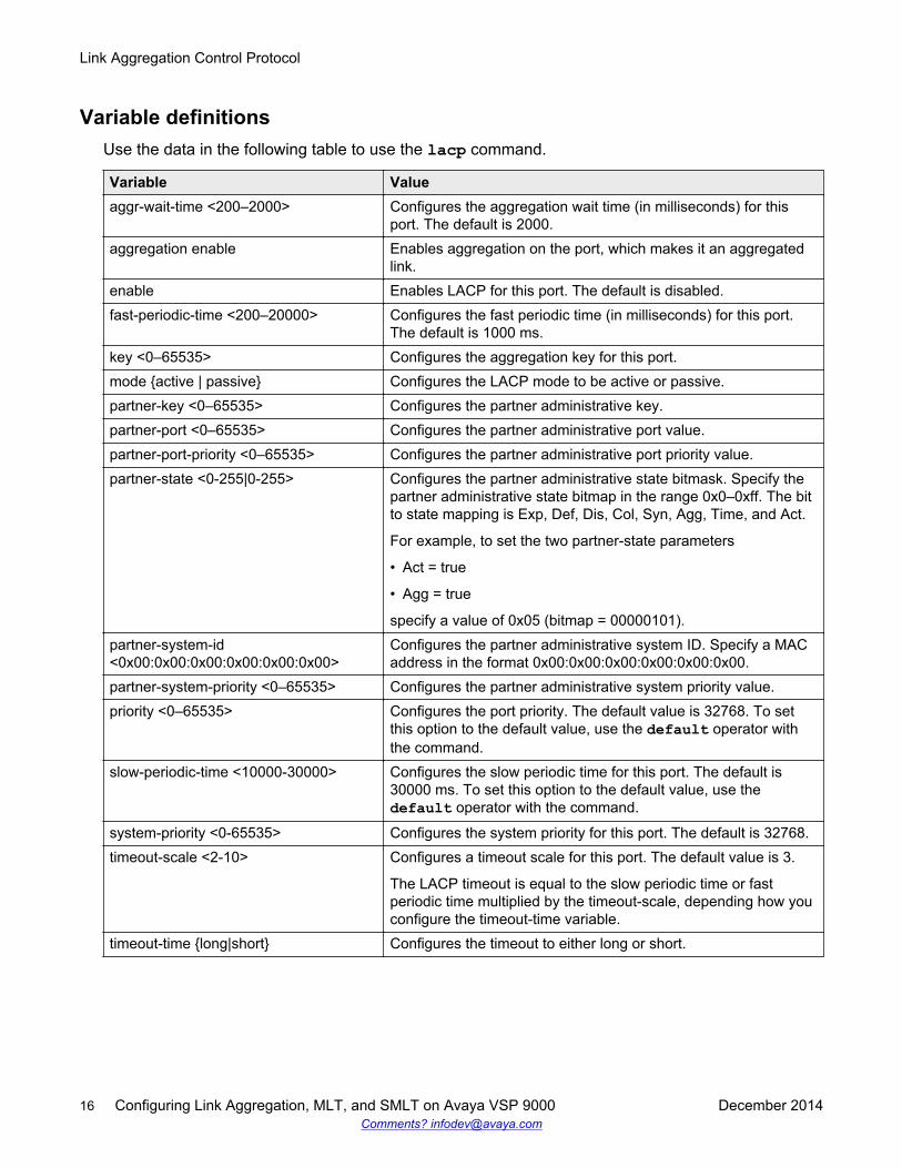
Variable definitionsUse the data in the following table to use the lacp command.
Variable Valueaggr-wait-time <200–2000> Configures the aggregation wait time (in milliseconds) for this
port. The default is 2000.aggregation enable Enables aggregation on the port, which makes it an aggregated
link.enable Enables LACP for this port. The default is disabled.fast-periodic-time <200–20000> Configures the fast periodic time (in milliseconds) for this port.
The default is 1000 ms.key <0–65535> Configures the aggregation key for this port.mode {active | passive} Configures the LACP mode to be active or passive.partner-key <0–65535> Configures the partner administrative key.partner-port <0–65535> Configures the partner administrative port value.partner-port-priority <0–65535> Configures the partner administrative port priority value.partner-state <0-255|0-255> Configures the partner administrative state bitmask. Specify the
partner administrative state bitmap in the range 0x0–0xff. The bitto state mapping is Exp, Def, Dis, Col, Syn, Agg, Time, and Act.
For example, to set the two partner-state parameters
• Act = true
• Agg = true
specify a value of 0x05 (bitmap = 00000101).partner-system-id<0x00:0x00:0x00:0x00:0x00:0x00>
Configures the partner administrative system ID. Specify a MACaddress in the format 0x00:0x00:0x00:0x00:0x00:0x00.
partner-system-priority <0–65535> Configures the partner administrative system priority value.priority <0–65535> Configures the port priority. The default value is 32768. To set
this option to the default value, use the default operator withthe command.
slow-periodic-time <10000-30000> Configures the slow periodic time for this port. The default is30000 ms. To set this option to the default value, use thedefault operator with the command.
system-priority <0-65535> Configures the system priority for this port. The default is 32768.timeout-scale <2-10> Configures a timeout scale for this port. The default value is 3.
The LACP timeout is equal to the slow periodic time or fastperiodic time multiplied by the timeout-scale, depending how youconfigure the timeout-time variable.
timeout-time {long|short} Configures the timeout to either long or short.
Link Aggregation Control Protocol
16 Configuring Link Aggregation, MLT, and SMLT on Avaya VSP 9000 December 2014Comments? [email protected]
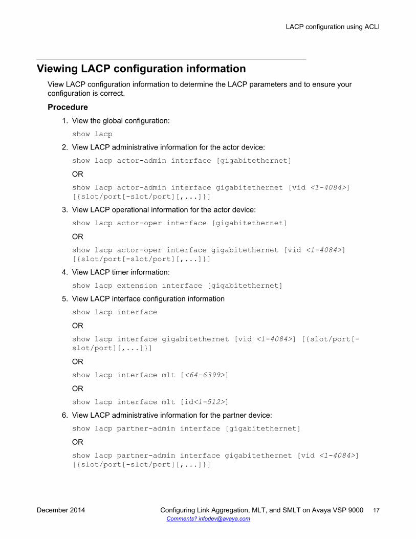
Viewing LACP configuration informationView LACP configuration information to determine the LACP parameters and to ensure yourconfiguration is correct.
Procedure1. View the global configuration:
show lacp2. View LACP administrative information for the actor device:
show lacp actor-admin interface [gigabitethernet]OR
show lacp actor-admin interface gigabitethernet [vid <1-4084>][{slot/port[-slot/port][,...]}]
3. View LACP operational information for the actor device:
show lacp actor-oper interface [gigabitethernet]OR
show lacp actor-oper interface gigabitethernet [vid <1-4084>][{slot/port[-slot/port][,...]}]
4. View LACP timer information:
show lacp extension interface [gigabitethernet]5. View LACP interface configuration information
show lacp interfaceOR
show lacp interface gigabitethernet [vid <1-4084>] [{slot/port[-slot/port][,...]}]OR
show lacp interface mlt [<64-6399>]OR
show lacp interface mlt [id<1-512>]6. View LACP administrative information for the partner device:
show lacp partner-admin interface [gigabitethernet]OR
show lacp partner-admin interface gigabitethernet [vid <1-4084>][{slot/port[-slot/port][,...]}]
LACP configuration using ACLI
December 2014 Configuring Link Aggregation, MLT, and SMLT on Avaya VSP 9000 17Comments? [email protected]

7. View LACP operational information for the partner device:
show lacp partner-oper interface [gigabitethernet]OR
show lacp partner-oper interface gigabitethernet [vid <1-4084>][{slot/port[-slot/port][,...]}]
ExampleVSP-9012:1#show lacp
================================================================================ Lacp Global Information================================================================================ SystemId: 00:24:7f:a1:70:00 SmltSystemId: 00:00:00:00:00:00 Lacp: enable system-priority: 32768 timeout-admin: 3 fast-periodic-time-admin: 1000 slow-periodic-time-admin: 30000 aggr-wait-time-admin: 2000 timeout-oper: 3 fast-periodic-time-oper: 2000 slow-periodic-time-oper: 30000 aggr-wait-time-oper: 2000
In the following example output, aggr indicates the port has become part of an aggregation. indiindicates individual.VSP-9012:1(config-if)#show lacp actor-admin interface gigabitethernet 4/21-4/22================================================================================ Actor Admin================================================================================INDEX SYS SYS KEY PORT PORT STATE PRIO ID PRIO--------------------------------------------------------------------------------4/21 32768 00:24:7f:9f:c0:00 1 0x114 32768 act short aggr4/22 32768 00:24:7f:9f:c0:00 1 0x115 32768 act short aggr
VSP-9012:1(config-if)#show lacp partner-admin interface gigabitethernet 4/21-4/22================================================================================ Partner Admin================================================================================INDEX SYS SYS KEY PORT PORT STATE PRIO ID PRIO--------------------------------------------------------------------------------4/21 0 00:00:00:00:00:00 0 0x0 0 pas long indi4/22 0 00:00:00:00:00:00 0 0x0 0 pas long indi
Variable definitionsUse the data in the following table to use the show lacp command.
Link Aggregation Control Protocol
18 Configuring Link Aggregation, MLT, and SMLT on Avaya VSP 9000 December 2014Comments? [email protected]
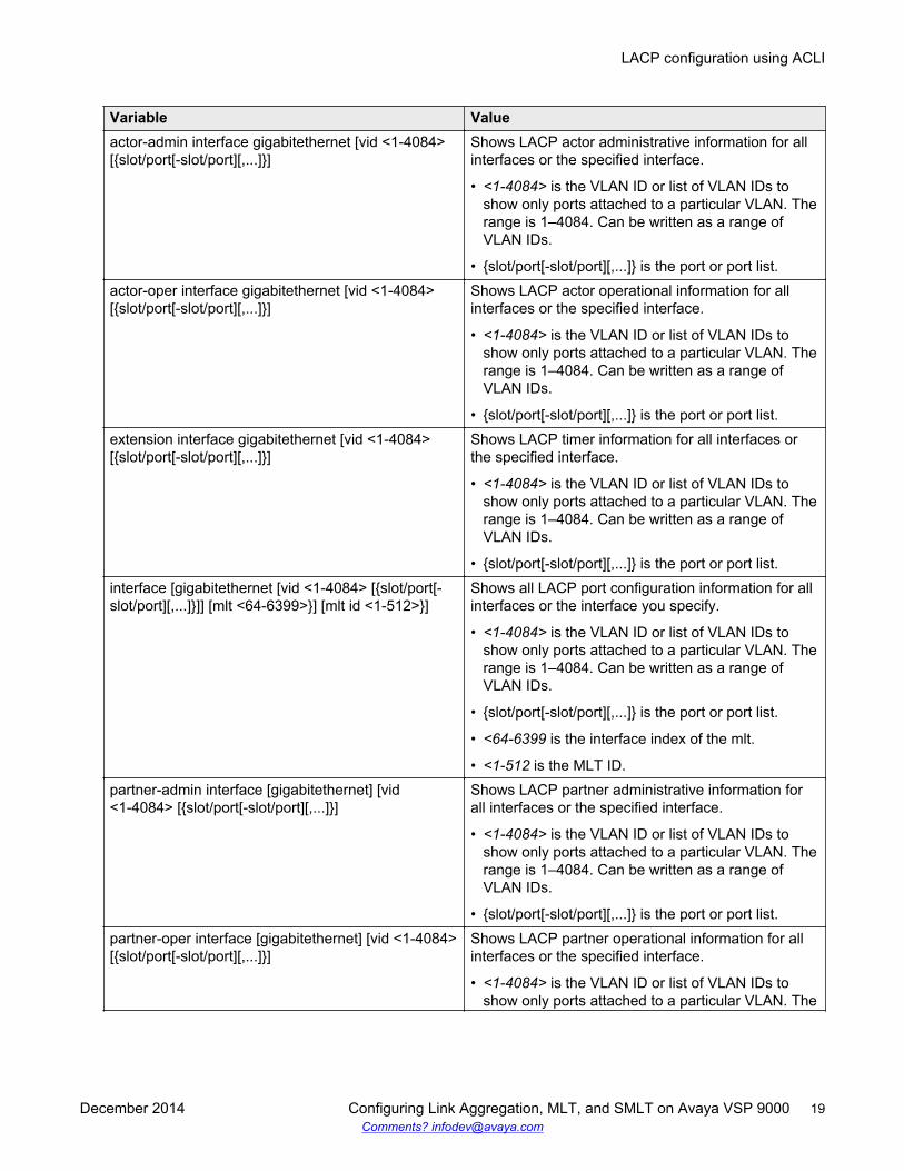
Variable Valueactor-admin interface gigabitethernet [vid <1-4084>[{slot/port[-slot/port][,...]}]
Shows LACP actor administrative information for allinterfaces or the specified interface.
• <1-4084> is the VLAN ID or list of VLAN IDs toshow only ports attached to a particular VLAN. Therange is 1–4084. Can be written as a range ofVLAN IDs.
• {slot/port[-slot/port][,...]} is the port or port list.actor-oper interface gigabitethernet [vid <1-4084>[{slot/port[-slot/port][,...]}]
Shows LACP actor operational information for allinterfaces or the specified interface.
• <1-4084> is the VLAN ID or list of VLAN IDs toshow only ports attached to a particular VLAN. Therange is 1–4084. Can be written as a range ofVLAN IDs.
• {slot/port[-slot/port][,...]} is the port or port list.extension interface gigabitethernet [vid <1-4084>[{slot/port[-slot/port][,...]}]
Shows LACP timer information for all interfaces orthe specified interface.
• <1-4084> is the VLAN ID or list of VLAN IDs toshow only ports attached to a particular VLAN. Therange is 1–4084. Can be written as a range ofVLAN IDs.
• {slot/port[-slot/port][,...]} is the port or port list.interface [gigabitethernet [vid <1-4084> [{slot/port[-slot/port][,...]}]] [mlt <64-6399>}] [mlt id <1-512>}]
Shows all LACP port configuration information for allinterfaces or the interface you specify.
• <1-4084> is the VLAN ID or list of VLAN IDs toshow only ports attached to a particular VLAN. Therange is 1–4084. Can be written as a range ofVLAN IDs.
• {slot/port[-slot/port][,...]} is the port or port list.
• <64-6399 is the interface index of the mlt.
• <1-512 is the MLT ID.partner-admin interface [gigabitethernet] [vid<1-4084> [{slot/port[-slot/port][,...]}]
Shows LACP partner administrative information forall interfaces or the specified interface.
• <1-4084> is the VLAN ID or list of VLAN IDs toshow only ports attached to a particular VLAN. Therange is 1–4084. Can be written as a range ofVLAN IDs.
• {slot/port[-slot/port][,...]} is the port or port list.partner-oper interface [gigabitethernet] [vid <1-4084>[{slot/port[-slot/port][,...]}]
Shows LACP partner operational information for allinterfaces or the specified interface.
• <1-4084> is the VLAN ID or list of VLAN IDs toshow only ports attached to a particular VLAN. The
LACP configuration using ACLI
December 2014 Configuring Link Aggregation, MLT, and SMLT on Avaya VSP 9000 19Comments? [email protected]
Variable Valuerange is 1–4084. Can be written as a range ofVLAN IDs.
• {slot/port[-slot/port][,...]} is the port or port list.
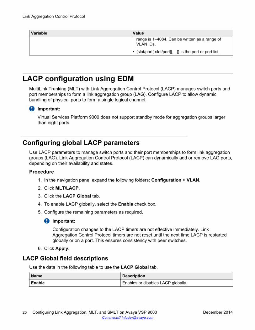
LACP configuration using EDMMultiLink Trunking (MLT) with Link Aggregation Control Protocol (LACP) manages switch ports andport memberships to form a link aggregation group (LAG). Configure LACP to allow dynamicbundling of physical ports to form a single logical channel.
Important:
Virtual Services Platform 9000 does not support standby mode for aggregation groups largerthan eight ports.
Configuring global LACP parametersUse LACP parameters to manage switch ports and their port memberships to form link aggregationgroups (LAG). Link Aggregation Control Protocol (LACP) can dynamically add or remove LAG ports,depending on their availability and states.
Procedure1. In the navigation pane, expand the following folders: Configuration > VLAN.
2. Click MLT/LACP.
3. Click the LACP Global tab.
4. To enable LACP globally, select the Enable check box.
5. Configure the remaining parameters as required.
Important:
Configuration changes to the LACP timers are not effective immediately. LinkAggregation Control Protocol timers are not reset until the next time LACP is restartedglobally or on a port. This ensures consistency with peer switches.
6. Click Apply.
LACP Global field descriptionsUse the data in the following table to use the LACP Global tab.
Name DescriptionEnable Enables or disables LACP globally.
Link Aggregation Control Protocol
20 Configuring Link Aggregation, MLT, and SMLT on Avaya VSP 9000 December 2014Comments? [email protected]
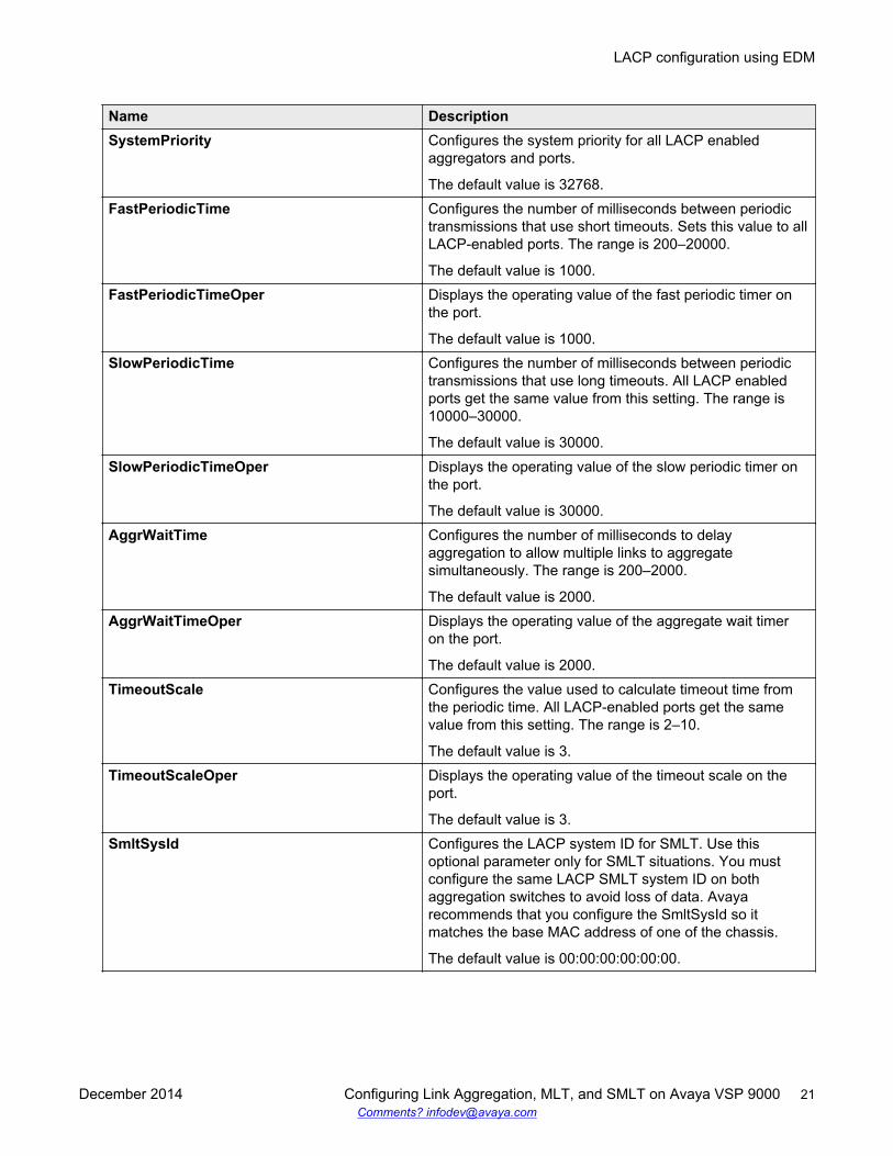
Name DescriptionSystemPriority Configures the system priority for all LACP enabled
aggregators and ports.
The default value is 32768.FastPeriodicTime Configures the number of milliseconds between periodic
transmissions that use short timeouts. Sets this value to allLACP-enabled ports. The range is 200–20000.
The default value is 1000.FastPeriodicTimeOper Displays the operating value of the fast periodic timer on
the port.
The default value is 1000.SlowPeriodicTime Configures the number of milliseconds between periodic
transmissions that use long timeouts. All LACP enabledports get the same value from this setting. The range is10000–30000.
The default value is 30000.SlowPeriodicTimeOper Displays the operating value of the slow periodic timer on
the port.
The default value is 30000.AggrWaitTime Configures the number of milliseconds to delay
aggregation to allow multiple links to aggregatesimultaneously. The range is 200–2000.
The default value is 2000.AggrWaitTimeOper Displays the operating value of the aggregate wait timer
on the port.
The default value is 2000.TimeoutScale Configures the value used to calculate timeout time from
the periodic time. All LACP-enabled ports get the samevalue from this setting. The range is 2–10.
The default value is 3.TimeoutScaleOper Displays the operating value of the timeout scale on the
port.
The default value is 3.SmltSysId Configures the LACP system ID for SMLT. Use this
optional parameter only for SMLT situations. You mustconfigure the same LACP SMLT system ID on bothaggregation switches to avoid loss of data. Avayarecommends that you configure the SmltSysId so itmatches the base MAC address of one of the chassis.
The default value is 00:00:00:00:00:00.
LACP configuration using EDM
December 2014 Configuring Link Aggregation, MLT, and SMLT on Avaya VSP 9000 21Comments? [email protected]

Configuring LACP parametersConfigure LACP parameters to manage LACP information.
About this taskImportant:The Virtual Services Platform 9000 does not support standby mode for aggregation groups oflarger than eight ports.
Procedure1. In the navigation pane, expand the following folders: Configuration > VLAN.
2. Click MLT/LACP.
3. Click the LACP tab.
4. Double-click a field to change the value.
You cannot edit grey-shaded fields in the table.
5. Click Apply.
LACP field descriptionsUse the data in the following table to use the LACP tab.
Name DescriptionIndex The unique identifier the local system allocates to this aggregator.
This attribute identifies an aggregator instance among thesubordinate managed objects of the containing object. This value isread-only.
MACAddress The six octet read-only value carrying the individual MAC addressassigned to the aggregator.
ActorSystemPriority The two octet read-write value indicating the priority value associatedwith the actor system ID.
The default value is 32768.ActorSystemID The six octet read-write MAC address value used as a unique
identifier for the system that contains this aggregator.
From the perspective of the link aggregation mechanisms, only asingle combination of actor system ID and system priority areconsidered. No distinction is made between the values of theseparameters for an aggregator and the ports that are associated withit. The protocol is described in terms of the operation of aggregationwithin a single system. However, the managed objects provided forthe both the aggregator and the port allow management of theseparameters. The result permits a single piece of equipment to beconfigured by management to contain more than one system from the
Link Aggregation Control Protocol
22 Configuring Link Aggregation, MLT, and SMLT on Avaya VSP 9000 December 2014Comments? [email protected]
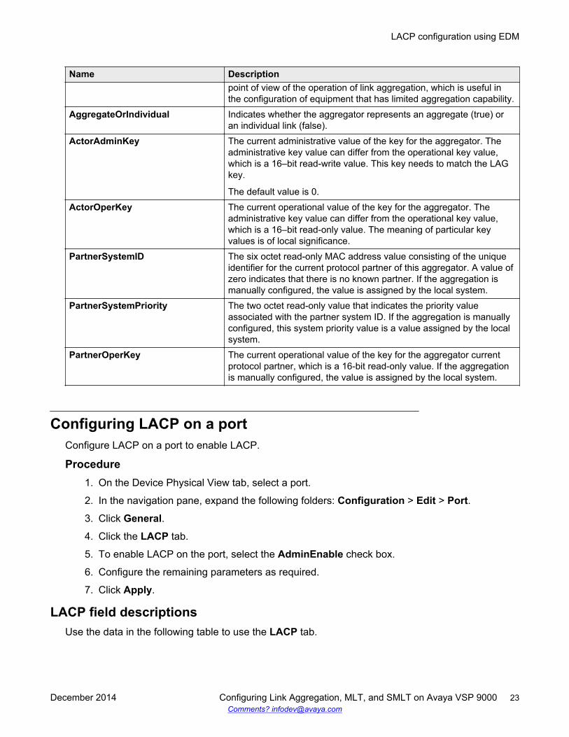
Name Descriptionpoint of view of the operation of link aggregation, which is useful inthe configuration of equipment that has limited aggregation capability.
AggregateOrIndividual Indicates whether the aggregator represents an aggregate (true) oran individual link (false).
ActorAdminKey The current administrative value of the key for the aggregator. Theadministrative key value can differ from the operational key value,which is a 16–bit read-write value. This key needs to match the LAGkey.
The default value is 0.ActorOperKey The current operational value of the key for the aggregator. The
administrative key value can differ from the operational key value,which is a 16–bit read-only value. The meaning of particular keyvalues is of local significance.
PartnerSystemID The six octet read-only MAC address value consisting of the uniqueidentifier for the current protocol partner of this aggregator. A value ofzero indicates that there is no known partner. If the aggregation ismanually configured, the value is assigned by the local system.
PartnerSystemPriority The two octet read-only value that indicates the priority valueassociated with the partner system ID. If the aggregation is manuallyconfigured, this system priority value is a value assigned by the localsystem.
PartnerOperKey The current operational value of the key for the aggregator currentprotocol partner, which is a 16-bit read-only value. If the aggregationis manually configured, the value is assigned by the local system.
Configuring LACP on a portConfigure LACP on a port to enable LACP.
Procedure1. On the Device Physical View tab, select a port.
2. In the navigation pane, expand the following folders: Configuration > Edit > Port.
3. Click General.
4. Click the LACP tab.
5. To enable LACP on the port, select the AdminEnable check box.
6. Configure the remaining parameters as required.
7. Click Apply.
LACP field descriptionsUse the data in the following table to use the LACP tab.
LACP configuration using EDM
December 2014 Configuring Link Aggregation, MLT, and SMLT on Avaya VSP 9000 23Comments? [email protected]
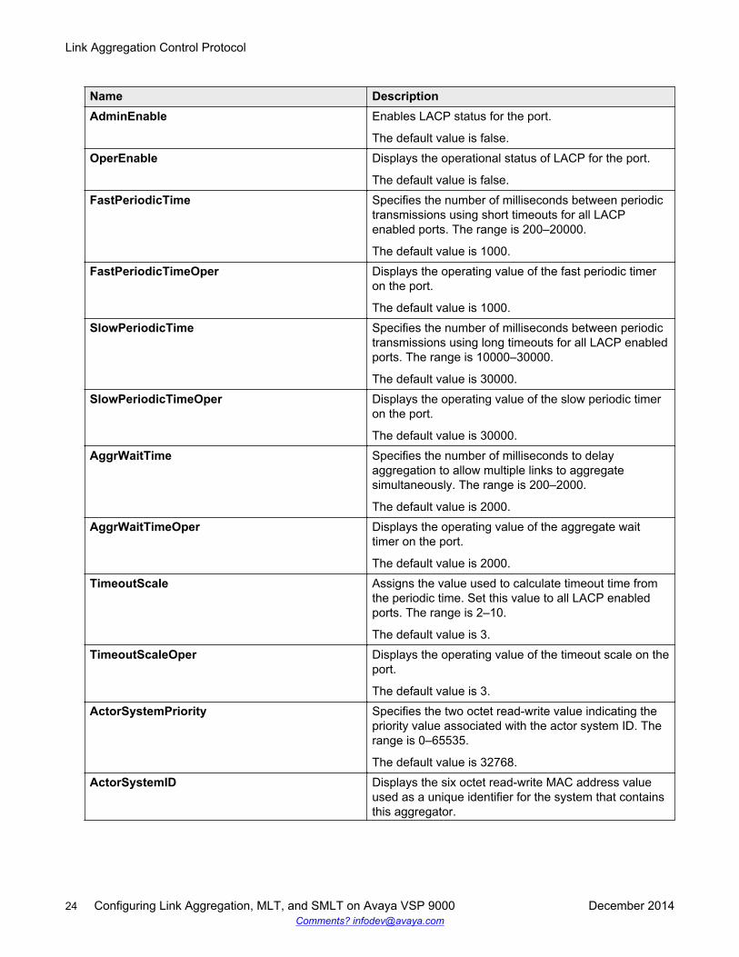
Name DescriptionAdminEnable Enables LACP status for the port.
The default value is false.OperEnable Displays the operational status of LACP for the port.
The default value is false.FastPeriodicTime Specifies the number of milliseconds between periodic
transmissions using short timeouts for all LACPenabled ports. The range is 200–20000.
The default value is 1000.FastPeriodicTimeOper Displays the operating value of the fast periodic timer
on the port.
The default value is 1000.SlowPeriodicTime Specifies the number of milliseconds between periodic
transmissions using long timeouts for all LACP enabledports. The range is 10000–30000.
The default value is 30000.SlowPeriodicTimeOper Displays the operating value of the slow periodic timer
on the port.
The default value is 30000.AggrWaitTime Specifies the number of milliseconds to delay
aggregation to allow multiple links to aggregatesimultaneously. The range is 200–2000.
The default value is 2000.AggrWaitTimeOper Displays the operating value of the aggregate wait
timer on the port.
The default value is 2000.TimeoutScale Assigns the value used to calculate timeout time from
the periodic time. Set this value to all LACP enabledports. The range is 2–10.
The default value is 3.TimeoutScaleOper Displays the operating value of the timeout scale on the
port.
The default value is 3.ActorSystemPriority Specifies the two octet read-write value indicating the
priority value associated with the actor system ID. Therange is 0–65535.
The default value is 32768.ActorSystemID Displays the six octet read-write MAC address value
used as a unique identifier for the system that containsthis aggregator.
Link Aggregation Control Protocol
24 Configuring Link Aggregation, MLT, and SMLT on Avaya VSP 9000 December 2014Comments? [email protected]
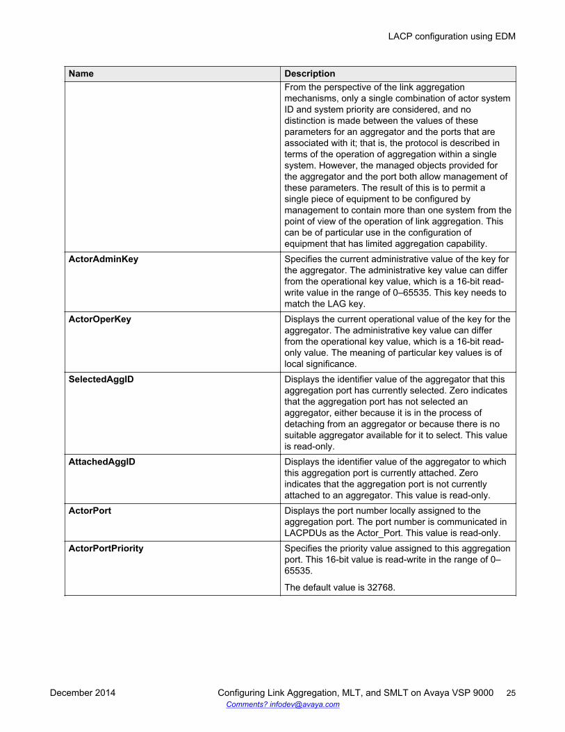
Name DescriptionFrom the perspective of the link aggregationmechanisms, only a single combination of actor systemID and system priority are considered, and nodistinction is made between the values of theseparameters for an aggregator and the ports that areassociated with it; that is, the protocol is described interms of the operation of aggregation within a singlesystem. However, the managed objects provided forthe aggregator and the port both allow management ofthese parameters. The result of this is to permit asingle piece of equipment to be configured bymanagement to contain more than one system from thepoint of view of the operation of link aggregation. Thiscan be of particular use in the configuration ofequipment that has limited aggregation capability.
ActorAdminKey Specifies the current administrative value of the key forthe aggregator. The administrative key value can differfrom the operational key value, which is a 16-bit read-write value in the range of 0–65535. This key needs tomatch the LAG key.
ActorOperKey Displays the current operational value of the key for theaggregator. The administrative key value can differfrom the operational key value, which is a 16-bit read-only value. The meaning of particular key values is oflocal significance.
SelectedAggID Displays the identifier value of the aggregator that thisaggregation port has currently selected. Zero indicatesthat the aggregation port has not selected anaggregator, either because it is in the process ofdetaching from an aggregator or because there is nosuitable aggregator available for it to select. This valueis read-only.
AttachedAggID Displays the identifier value of the aggregator to whichthis aggregation port is currently attached. Zeroindicates that the aggregation port is not currentlyattached to an aggregator. This value is read-only.
ActorPort Displays the port number locally assigned to theaggregation port. The port number is communicated inLACPDUs as the Actor_Port. This value is read-only.
ActorPortPriority Specifies the priority value assigned to this aggregationport. This 16-bit value is read-write in the range of 0–65535.
The default value is 32768.
LACP configuration using EDM
December 2014 Configuring Link Aggregation, MLT, and SMLT on Avaya VSP 9000 25Comments? [email protected]
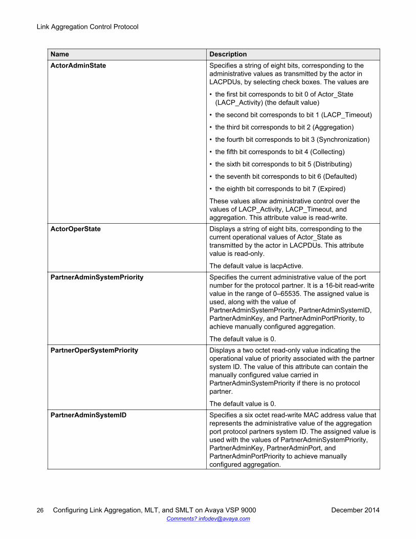
Name DescriptionActorAdminState Specifies a string of eight bits, corresponding to the
administrative values as transmitted by the actor inLACPDUs, by selecting check boxes. The values are
• the first bit corresponds to bit 0 of Actor_State(LACP_Activity) (the default value)
• the second bit corresponds to bit 1 (LACP_Timeout)
• the third bit corresponds to bit 2 (Aggregation)
• the fourth bit corresponds to bit 3 (Synchronization)
• the fifth bit corresponds to bit 4 (Collecting)
• the sixth bit corresponds to bit 5 (Distributing)
• the seventh bit corresponds to bit 6 (Defaulted)
• the eighth bit corresponds to bit 7 (Expired)
These values allow administrative control over thevalues of LACP_Activity, LACP_Timeout, andaggregation. This attribute value is read-write.
ActorOperState Displays a string of eight bits, corresponding to thecurrent operational values of Actor_State astransmitted by the actor in LACPDUs. This attributevalue is read-only.
The default value is lacpActive.PartnerAdminSystemPriority Specifies the current administrative value of the port
number for the protocol partner. It is a 16-bit read-writevalue in the range of 0–65535. The assigned value isused, along with the value ofPartnerAdminSystemPriority, PartnerAdminSystemID,PartnerAdminKey, and PartnerAdminPortPriority, toachieve manually configured aggregation.
The default value is 0.PartnerOperSystemPriority Displays a two octet read-only value indicating the
operational value of priority associated with the partnersystem ID. The value of this attribute can contain themanually configured value carried inPartnerAdminSystemPriority if there is no protocolpartner.
The default value is 0.PartnerAdminSystemID Specifies a six octet read-write MAC address value that
represents the administrative value of the aggregationport protocol partners system ID. The assigned value isused with the values of PartnerAdminSystemPriority,PartnerAdminKey, PartnerAdminPort, andPartnerAdminPortPriority to achieve manuallyconfigured aggregation.
Link Aggregation Control Protocol
26 Configuring Link Aggregation, MLT, and SMLT on Avaya VSP 9000 December 2014Comments? [email protected]
Name DescriptionThe default value is 00:00:00:00:00:00.
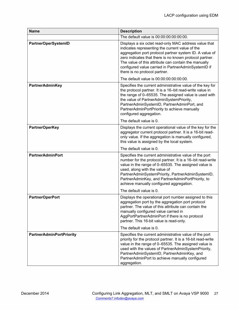
PartnerOperSystemID Displays a six octet read-only MAC address value thatindicates representing the current value of theaggregation port protocol partner system ID. A value ofzero indicates that there is no known protocol partner.The value of this attribute can contain the manuallyconfigured value carried in PartnerAdminSystemID ifthere is no protocol partner.
The default value is 00:00:00:00:00:00.PartnerAdminKey Specifies the current administrative value of the key for
the protocol partner. It is a 16–bit read-write value inthe range of 0–65535. The assigned value is used withthe value of PartnerAdminSystemPriority,PartnerAdminSystemID, PartnerAdminPort, andPartnerAdminPortPriority to achieve manuallyconfigured aggregation.
The default value is 0.PartnerOperKey Displays the current operational value of the key for the
aggregator current protocol partner. It is a 16-bit read-only value. If the aggregation is manually configured,this value is assigned by the local system.
The default value is 0.PartnerAdminPort Specifies the current administrative value of the port
number for the protocol partner. It is a 16–bit read-writevalue in the range of 0–65535. The assigned value isused, along with the value ofPartnerAdminSystemPriority, PartnerAdminSystemID,PartnerAdminKey, and PartnerAdminPortPriority, toachieve manually configured aggregation.
The default value is 0.PartnerOperPort Displays the operational port number assigned to this
aggregation port by the aggregation port protocolpartner. The value of this attribute can contain themanually configured value carried inAggPortPartnerAdminPort if there is no protocolpartner. This 16-bit value is read-only.
The default value is 0.PartnerAdminPortPriority Specifies the current administrative value of the port
priority for the protocol partner. It is a 16-bit read-writevalue in the range of 0–65535. The assigned value isused with the values of PartnerAdminSystemPriority,PartnerAdminSystemID, PartnerAdminKey, andPartnerAdminPort to achieve manually configuredaggregation.
LACP configuration using EDM
December 2014 Configuring Link Aggregation, MLT, and SMLT on Avaya VSP 9000 27Comments? [email protected]

Name DescriptionThe default value is 0.
PartnerOperPortPriority Displays the priority value assigned to this aggregationport by the partner. The value of this attribute cancontain the manually configured value carried inPartnerAdminPortPriority if there is no protocol partner.This 16 bit value is read-only.
The default value is 0.PartnerAdminState Specifies a string of eight bits, corresponding to the
current administrative value of Actor_State for theprotocol partner, by selecting check boxes. Thisattribute value is read-write. The assigned value isused to achieve manually configured aggregation.
The default value is none.PartnerOperState Displays a string of eight bits, corresponding to the
current values of Actor_State in the most recentlyreceived LACPDU transmitted by the protocol partner.In the absence of an active protocol partner, this valuecan reflect the manually configured valuePartnerAdminState. This attribute value is read-only.
The default value is none.
Link Aggregation Control Protocol
28 Configuring Link Aggregation, MLT, and SMLT on Avaya VSP 9000 December 2014Comments? [email protected]
Chapter 4: MultiLink Trunking and SplitMultiLink Trunking
This section provides the concepts and procedures you need to configure MultiLink Trunking (MLT)and Split MultiLink Trunking (SMLT).
Link aggregation overviewLink aggregation provides link level redundancy and increases load sharing. Use Link aggregationto bundle the ports into a port group, which is represented as one logical interface to the MediaAccess Control (MAC) layer.
The Avaya Virtual Services Platform 9000 supports the following types of link aggregation:
• MultiLink Trunking (MLT)—a statically configured link bundling method. MLT is not standardsbased, but it interoperates with static link methods of other vendors. If you aggregate links frommultiple modules together, MLT can provide not only port redundancy, but also moduleredundancy.
• IEEE 802.3ad based link aggregation, through the Link Aggregation Control Protocol (LACP),dynamically aggregates links as they become available to a trunk group. Link AggregationControl Protocol dynamically detects whether links can be aggregated into a link aggregationgroup (LAG) and does so after links become available. Link Aggregation Control Protocol alsoprovides link integrity checking at Layer 2 for all links within the LAG.
Both MLT and IEEE 802.3ad based link aggregation are point-to-point functions.
The Virtual Services Platform 9000 software offers LACP functionality layered with MLT. Thisdocument uses the term MLT with LACP to refer to this functionality.
An Interswitch Trunk (IST) is a special form of aggregate link. ISTs use a link aggregationmechanism such as a Multilink Trunk (MLT) to create a single logical switch out of two physicaldevices. Creating one logical switch allows the devices to share resources, enhance fault tolerance,and create network redundancy.
Split MultiLink Trunking (SMLT) is an option that improves Layer 2 (bridged) resiliency by providingfor the addition of a Virtual Services Platform 9000 failure redundancy with subsecond failover, ontop of all standard MLT link failure protection and flexible bandwidth scaling functionality. Use SMLTto connect a device that supports some form of link aggregation, be it a switch or a server, to two
December 2014 Configuring Link Aggregation, MLT, and SMLT on Avaya VSP 9000 29Comments? [email protected]
distinct separate SMLT endpoints or switches. These SMLT devices form a Switch Cluster and arereferred to as an Interswitch Trunk (IST) Core Switch pair.
You can also use LACP on SMLT configurations. The Virtual Services Platform 9000 providesmodifications to the LACP in SMLT configurations. LACP-capable devices can connect to an SMLTaggregation pair. Avaya recommends that you do not configure LACP on the IST MLT.
Virtual LACP (VLACP) is an Avaya modification that provides end-to-end failure detection. TheVLACP is not a link aggregation protocol; VLACP implements link status control protocol at the portlevel. This mechanism periodically checks the end-to-end health of a point-to-point or end-to-endconnection. You can run VLACP on single ports or on ports that are part of an MLT. Avayarecommends that you do not configure VLACP on LACP-enabled ports. Virtual LACP does notoperate properly with LACP. You can configure VLACP with an SMLT configuration.
MultiLink TrunkingMultiLink Trunking (MLT) is a point-to-point connection that aggregates multiple ports to logically actlike a single port with aggregated bandwidth. Grouping multiple ports into a logical link provides ahigher aggregate on a switch-to-switch or switch-to-server application.
To include ports as trunk group members of an MLT, you must statically configure the ports.
MLT traffic distribution algorithmYou can use a multilink trunk to aggregate bandwidth between two switches. The Virtual ServicesPlatform 9000 uses one of two algorithms to determine which active port in the multilink trunk to usefor each packet. The MLT algorithms provide load sharing, not load balancing. The MLT algorithmsensure that each packet in a flow does not arrive out of sequence, and that a flow always traversesthe same link path.
The algorithms are the same traffic distribution algorithms used for the IEEE 802.3ad based linkaggregation.
For more information about port and algorithm calculations, see Viewing the MLT port calculated bythe MLT hash algorithm on page 53.
The Virtual Services Platform 9000 uses an enhanced traffic distribution algorithm, which ensuresproper traffic distribution in all customer networks. The system determines MultiLink Trunkinghashing for a module type at the ingress port, although the effect is seen at the egress MLT. That is,the traffic ingressing a port determines the destination is an MLT and sends the traffic to thecorrectly hashed MLT port, regardless of MLT port type or even a mixed port type. Therefore, in amixed chassis, the algorithm used is based on the ingress port for the traffic, not the MLTconfiguration.
The hashing algorithm for IPv4 TCP/UDP traffic is as follows
64-bit key = (SrcPort (16 bits), DstPORT (16 bits), DstIP (LSB 16 bits), SrcIP (LSB 16 bits))
For non-TCP/UDP IPv4 traffic
64-bit key = [DstIP (32 bits), SrcIP (32 bits)]
For IPv6, the MLT hashing algorithm is:
MultiLink Trunking and Split MultiLink Trunking
30 Configuring Link Aggregation, MLT, and SMLT on Avaya VSP 9000 December 2014Comments? [email protected]
64-bit key = SrcIP(LSB 64 bits) XOR SrcIP(MSB 64 bits) XOR DstIP(LSB 64 bits) XOR DstIP(MSB64 bits)
For non IP/IPv6 traffic, the MLT hashing algorithm is:
64-bit key = [Dst Mac (LSB 32 bits), Src Mac (LSB 32 bits)]
The 64-bit key result is used as an index to a table populated with active MLT ports repeated over63 entries.
Use the hash-calc getmltindex command to configure src-port and dst-port as optionalparameters.
The hashing for IPv4 traffic between a given source and destination IP address is different forTCP/UDP packets and ICMP packets.
MultiLink trunking and autonegotiation interactionTo use MLT with the Virtual Services Platform 9000, you can have 10Gb and 1Gb ports running atdifferent speeds. After you use MLT with LACP, LACP dynamically checks for proper speed on allport members. You do not need to have similar physical connection types. For example, you canmix a fiber port with a copper port. After you use autonegotiation with MLT and not LACP, you needto ensure that all ports run at the same speed.
Multicast flow distribution over MLTMultiLink Trunking provides a mechanism to distribute multicast streams over a multilink trunk. Thismechanism is based on source-subnet and group addresses. You can use it to choose the addressand bytes in the address for the distribution algorithm.
The multicast flow distribution over MLT algorithm is the same multicast flow distribution algorithmused in IEEE 802.3ad based link aggregation. As a result, you can distribute the load on the MLTports and achieve even stream distribution. In applications such as television (TV) distribution,multicast traffic distribution is important because bandwidth requirements are substantial after alarge number of TV streams are employed.
With flow distribution over MLT, Avaya recommends that you choose source and group masks thatresult in even traffic distribution over the multilink trunk links.
For more information about multicast flow distribution over MLT, see Configuring IP MulticastRouting Protocols on Avaya Virtual Services Platform 9000, NN46250-504.
Multicast distribution algorithmThe multicast hashing algorithm is the same algorithm used for an IP packet. For more information,see MLT traffic distribution algorithm on page 30.
MLT and MLT with LACP configuration rulesVirtual Services Platform 9000 multilink trunks adhere to the following rules. Unless otherwisestated, these rules also apply to MLT with LACP.
• MLT is supported on 10Base-T, 100Base-TX, Gigabit Ethernet, and 10 Gigabit Ethernetmodule ports.
• Multilink trunk ports support mixed speed links, for example, one link can be 10Gb and another1Gb. However, no weighting of traffic distribution occurs so if you mix links of differentoperational speeds, you can overload the lower speed link or under utilize a higher speed link.
This rule applies to multilink trunks only. MLT with LACP does not support different link speeds.
MultiLink Trunking
December 2014 Configuring Link Aggregation, MLT, and SMLT on Avaya VSP 9000 31Comments? [email protected]
• The media type of MLT ports can be different; a mix of copper and fiber are allowed.• All multilink trunk ports must be in the same Spanning Tree Group (STG) unless the port is
tagged. Use tagging so ports can belong to multiple STGs, as well as multiple VLANs.• After the port is made a member of MLT, it inherits the properties of the MLT and hence the
STG properties are inherited from the VLAN associated with that MLT. After you remove theport from MLT or after you delete the MLT, the ports are removed from the MLT STG andadded into the default STG.
• MLT is compatible with Multiple Spanning Tree Protocol (MSTP) (IEEE 802.1s) and RapidSpanning Tree Protocol (RSTP) (IEEE 802.1w).
• Tagging (IEEE 802.1Q) is supported on a multilink trunk.
Virtual Services Platform 9000 multilink trunks have the following general features andrequirements:
• Supports up to 512 MLT groups with as many as 16 ports belonging to a single multilink trunk.• MLT ports can span modules, providing module redundancy.• Apply filters individually to each port in a multilink trunk.
With MSTP or RSTP enabled, ports in the same multilink trunk operate as follows:
• The designated port sends the Bridge Protocol Data Unit (BPDU).• The multilink trunk port ID is the ID of the lowest numbered port.• If identical BPDUs are received on all ports, the multilink trunk mode is forwarding.• If ports do not receive BPDUs on a port or BPDU and port tagging do not match, the individual
port is taken offline.• Path cost is inversely proportional to the active multilink trunk bandwidth.
LAG rulesThe Virtual Services Platform 9000 Link Aggregation Groups (LAG) adhere to the following rules:
• All LAG ports operate in full-duplex mode.• All LAG ports operate at the same data rate.• All LAG ports must belong to the same set of VLANs.• Link aggregation is compatible with MSTP, and RSTP.• Assign all LAG ports to the same MSTP or RSTP groups.• Ports in a LAG can exist on different modules.• Support a maximum of 32 link aggregation groups.• You can configure a LAG with up to 16 ports, but only a maximum of 8 can be active at a time.• After you configure a multilink trunk with LACP, you cannot add or delete ports manually
without first disabling LACP.
MultiLink Trunking and Split MultiLink Trunking
32 Configuring Link Aggregation, MLT, and SMLT on Avaya VSP 9000 December 2014Comments? [email protected]
MultiLink Trunking with LACPMultiLink Trunking (MLT) with Link Aggregation Control Protocol (LACP) manages ports and portmemberships to form a link aggregation group (LAG). Use Link Aggregation Control Protocol togather one or more links to form a LAG, which a Media Access Control (MAC) client treats as asingle link. Link Aggregation Control Protocol can dynamically add or remove LAG ports, dependingon availability and state.
IEEE 802.3ad overviewThe IEEE 802.3ad standard comprises service interfaces, the LACP, the Marker Protocol, linkaggregation selection logic, a parser or multiplexer, frame distribution, and frame collectionfunctions.
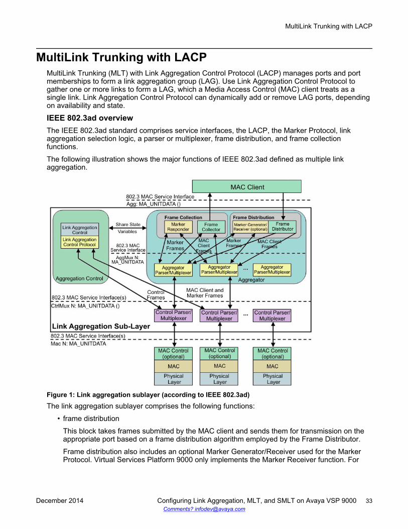
The following illustration shows the major functions of IEEE 802.3ad defined as multiple linkaggregation.
Figure 1: Link aggregation sublayer (according to IEEE 802.3ad)The link aggregation sublayer comprises the following functions:
• frame distribution
This block takes frames submitted by the MAC client and sends them for transmission on theappropriate port based on a frame distribution algorithm employed by the Frame Distributor.
Frame distribution also includes an optional Marker Generator/Receiver used for the MarkerProtocol. Virtual Services Platform 9000 only implements the Marker Receiver function. For
MultiLink Trunking with LACP
December 2014 Configuring Link Aggregation, MLT, and SMLT on Avaya VSP 9000 33Comments? [email protected]
more information about the frame distribution algorithm, see MLT traffic distributionalgorithm on page 30.
• frame collection
This block passes frames received from the various ports to the MAC client. Frame collectionalso includes a Marker Responder used for the Marker Protocol.
• aggregator parser or multiplexers
During transmission operations, these blocks pass frame transmission requests from theDistributor, Marker Generator, and Marker Responder to the appropriate port.
During receive operations, these blocks distinguish among Marker Request, Marker Response,MAC Client Protocol Data Units (PDU), and pass the blocks to the appropriate entity (MarkerResponder, Marker Receiver, and Collector, respectively).
• aggregator
The combination of frame distribution and collection, and aggregator parser or multiplexers.• aggregation control
This block configures and controls link aggregation. It incorporates LACP for the automaticcommunication of aggregation capabilities between systems and automatic configuration of linkaggregation.
• control parser/multiplexers
During transmission operations, these blocks pass frame transmission requests from theaggregator and Control entities to the appropriate port.
During receive operations, these blocks distinguish Link Aggregation Control Protocol DataUnits (LACPDUs) from other frames. The blocks pass, passing the LACPDUs to theappropriate sublayer entity and all other frames to the aggregator.
802.3ad link aggregation principlesUse link aggregation to group ports together to form a link group to another device. Link groupsincrease aggregate throughput between devices and provide link redundancy.
Link aggregation employs the following principles and concepts:
• A MAC client communicates with a set of ports through an aggregator, which presents astandard IEEE 802.3 service interface to the MAC client. The aggregator binds to one or moreports within a system.
• The aggregator distributes frame transmissions from the MAC client to various ports, collectsreceived frames from the ports, and transparently passes the frames to the MAC client.
• A system can contain multiple aggregators serving multiple MAC clients. A port binds to asingle aggregator at a time. A MAC client is served by a single aggregator at a time.
• The Link Aggregation Control function binds ports to aggregators within a system. The controlfunction aggregates links, binds the system ports to an appropriate aggregator, and monitorsconditions to determine if a change in aggregation is needed. Network managers can manuallyprovide link aggregation control by manipulating the link aggregation state variables (forexample, keys). You can also use LACP to automatically determine, configure, bind, andmonitor link aggregation.
• LACP uses peer exchanges across links to continually determine the aggregation capability ofthe links and provide the maximum level of aggregation capability between a pair of systems.
MultiLink Trunking and Split MultiLink Trunking
34 Configuring Link Aggregation, MLT, and SMLT on Avaya VSP 9000 December 2014Comments? [email protected]
• Frame ordering is maintained for certain sequences of frame exchanges between MAC Clients.The distributor ensures that all frames of a conversation pass to a single port. The collectorpasses frames to the MAC client in the order they are received from the port. The collector canselect frames received from the aggregated ports. Because the frames are not ordered on asingle link, this guarantees that frame ordering is maintained for all conversations.
• Conversations move among ports within an aggregation for load balancing and for maintainingavailability if a link fails.
• The standard does not impose a particular distribution algorithm on the distributor. The VirtualServices Platform 9000 uses the MLT traffic distribution algorithm. For more information on theVirtual Services Platform 9000 traffic distribution algorithm, see MLT traffic distributionalgorithm on page 30.
• Each port is assigned a unique, globally administered MAC address.
After entities initiate frame exchanges within the link aggregation sublayer, the source addressis the MAC address. An example of an entity that initiates frame exchanges is LACP andMarker Protocol exchanges.
• Each aggregator is assigned a unique, globally administered MAC address that is used fromthe perspective of the MAC client, both as a source address for transmitted frames and as thedestination address for received frames. You can use one of the port MAC addresses in theassociated LAG as the MAC address of the aggregator.
Split MultiLink TrunkingSplit MultiLink Trunking (SMLT) is an option that improves Layer 2 and Layer 3 resiliency. Thefollowing sections discuss SMLT in more detail.
SMLT overviewSplit MultiLink Trunking is an option that improves Layer 2 (bridged) resiliency by providing for theaddition of Virtual Services Platform 9000 failure redundancy with subsecond failover, on top of allstandard MLT link failure protection and flexible bandwidth scaling functionality. Use Split MultiLinkTrunking to connect a device which supports some form of link aggregation, be it a switch or aserver, to two distinct separate SMLT endpoints or switches. These SMLT devices form a SwitchCluster and are referred to as an interswitch trunk (IST) Core Switch pair.
Switch Clusters are always formed as a pair, but you can combine pairs of clusters in either asquare or full-mesh fashion to increase the size and port density of the Switch Cluster. If youconfigure SMLT in a Layer 3 or routed topology, the configuration is referenced as Routed SMLT(RSMLT). For information about Routed SMLT, see Configuring IP Routing on Avaya VirtualServices Platform 9000, NN46250-505.
You can form SMLT connections through single links from the Switch Cluster to the edgeconnection, standard MLTs, or MLTs with LACP. Optionally, SMLT links can have VLACP enabledas well. You can mix these various link connections. Within the same Switch Cluster, you canconfigure both SMLT and RSMLT to allow a mixture of both Layer 2 and Layer 3 VLANs. For moreinformation about various SMLT configurations, see SMLT topologies on page 37.
Split MultiLink Trunking networks do not need to use RSTP or MSTP to enable loop-free triangletopologies because SMLT inherently avoids loops due to its superior enhanced link aggregationprotocol. The loop-free link is accomplished by having two aggregation switches appear as a single
Split MultiLink Trunking
December 2014 Configuring Link Aggregation, MLT, and SMLT on Avaya VSP 9000 35Comments? [email protected]
device to edge switches, which dual-home to the aggregation switches. The aggregation switchesinterconnect using an interswitch trunk, exchanging addressing and state information (permittingrapid fault detection and forwarding path modification). Split MultiLink Trunking is designed for Layer2 network connectivity, but you can configure in Layer 3 networks by working with VRRP or RSMLTLayer 2 edge.
For more information about SMLT configuration, see Switch Clustering using Split-MultiLinkTrunking (SMLT) with VSP 9000, ERS 8600/8800, 8300, and 5000 Technical Configuration Guide,NN48500-518. For more information about the technical configuration guide, go to the Avaya Website: http://support.avaya.com.
SMLT advantagesSMLT eliminates all single points of failure and creates multiple paths from all user access switchesto the network core. In case of failure, SMLT recovers as quickly as possible using all capacity.SMLT provides a transparent and interoperable solution that requires no modification on the part ofthe majority of existing user access devices.
SMLT improves the reliability of Layer 2 networks that operate between user access switches andthe network center aggregation switch by providing:
• load sharing among all links• fast failover in case of link failure• elimination of single points of failure• fast recovery in case of node failure• transparent and interoperable solutions• removal of MSTP and RSTP convergence issues
SMLT, MSTP, and RSTPNetworks designed to have user access switches dual-home to two aggregation switches, and haveVLANs spanning two or more user access switches, experience the following design constraints:
• no load sharing exists over redundant links• network convergence is slow in case of failure
With the introduction of SMLT, all dual-home Layer 2 frame-switched network devices with dualhomes are no longer dependent on the MSTP or RSTP for loop detection. A properly designedSMLT network inherently does not have logical loops.
SMLT solves the spanning tree problem by combining two aggregation switches into one logicalMLT entity, thus making it transparent to all types of edge switches. In the process, it provides quickconvergence, while load sharing across all available trunks.
If you use STP mode on a switch that is in an SMLT configuration with Virtual Services Platform9000 systems, you can experience traffic loss for 30 seconds if you change the port membership ofthe MLT, even if the port is in a down state. The traffic loss is because the convergence time forSTP is 30 seconds. Avaya recommends that you use MSTP or RSTP on all switches in SMLTconfigurations.
MultiLink Trunking and Split MultiLink Trunking
36 Configuring Link Aggregation, MLT, and SMLT on Avaya VSP 9000 December 2014Comments? [email protected]
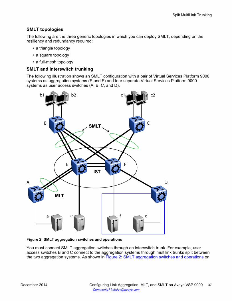
SMLT topologiesThe following are the three generic topologies in which you can deploy SMLT, depending on theresiliency and redundancy required:
• a triangle topology• a square topology• a full-mesh topology
SMLT and interswitch trunkingThe following illustration shows an SMLT configuration with a pair of Virtual Services Platform 9000systems as aggregation systems (E and F) and four separate Virtual Services Platform 9000systems as user access switches (A, B, C, and D).
Figure 2: SMLT aggregation switches and operations
You must connect SMLT aggregation switches through an interswitch trunk. For example, useraccess switches B and C connect to the aggregation systems through multilink trunks split betweenthe two aggregation systems. As shown in Figure 2: SMLT aggregation switches and operations on
Split MultiLink Trunking
December 2014 Configuring Link Aggregation, MLT, and SMLT on Avaya VSP 9000 37Comments? [email protected]
page 37, the implementation of SMLT only requires two SMLT-capable aggregation systems. Youmust connect these Virtual Services Platform 9000 systems through an interswitch trunk.
Aggregation switches use the interswitch trunk to do the following:
• Confirm that they are alive and exchange MAC address forwarding tables.• Send traffic between single switches attached to the aggregation switches.• Serve as a backup if one SMLT link fails.
Because SMLT requires the interswitch trunk, Avaya recommends that you use multiple links on theinterswitch trunk to ensure reliability and high availability. Avaya also recommends that you useGigabit Ethernet links for interswitch trunk connectivity to provide enough bandwidth for potentialcross traffic.
If the SMLT interfaces from one of the IST peers are down, all MAC entries and IP AddressResolution Protocol (ARP) entries learned from SMLT interfaces are unchanged. This behavior isdifferent than on Avaya Ethernet Routing Switch 8600, where all corresponding MAC and ARPentries are converted to be learned from the IST interface.
Avaya recommends that an interswitch multilink trunk contain at least two physical ports. Youcannot enable the CP-Limit on all physical ports that are members of an interswitch trunk multilinktrunk.
Important:Avaya does not allow you to enable the CP-Limit on the IST MLT in the VSP 9000.
Disabling the CP-Limit on interswitch trunk multilink trunk ports forces another, less-critical port to bedisabled if the defined CP Limits are exceeded. This preserves network stability if a protectioncondition (CP-Limit) arises. You can disable one of the multilink trunk ports (risers) in such acondition; traffic continues to flow uninterrupted through the remaining SMLT ports.
For more information about CP-Limit, see Administering Avaya Virtual Services Platform 9000,NN46250-600.
Other SMLT aggregation switch connectionsThe example shown in Figure 2: SMLT aggregation switches and operations on page 37 includesend stations that connect to each of the Virtual Services Platform 9000 systems. In this example, a,b1, b2, c1, c2, and d are clients and printers, while e and f are servers and routers.
User access switches B and C can use a method to determine which link of the multilink trunkconnections to use to forward a packet, as long as the same link is used for a Source Address andDestination Address (SA/DA) pair. The packet is routed correctly regardless of whether B or Cknows the DA. SMLT aggregation switches always send traffic directly to a user access switch, andonly use the interswitch trunk for traffic that they cannot forward in another, more direct way.
SMLT environment traffic flow rulesTraffic flow in an SMLT environment adheres to the following rules:
• If a packet is received from an interswitch trunk port, it is not forwarded to an active SMLTgroup in order to prevent network loops.
• After a packet is received, the system performs a look-up on the forwarding database. If anentry exists, and if the entry was learned locally from the SMLT or through the IST as a remoteSMLT, it is forwarded to the local port (the packet must not be sent to the IST for forwarding
MultiLink Trunking and Split MultiLink Trunking
38 Configuring Link Aggregation, MLT, and SMLT on Avaya VSP 9000 December 2014Comments? [email protected]
unless there is no local connection). Unknown and Broadcast packets flood out all ports thatare members of this VLAN.
• For load sharing purposes in an SMLT configuration, the Virtual Services Platform 9000 obeysthe MLT traffic distribution algorithm.
SMLT traffic flow examplesThe following traffic flow examples are based on Figure 2: SMLT aggregation switches andoperations on page 37.
Example 1: Traffic flow from a to b1 or b2Assuming a and b1/b2 are communicating through Layer 2, traffic flows from A to switch E and isforwarded over its direct link to B. Traffic coming from b1 or b2 to a is sent by B on one of itsmultilink trunk ports.
B can send traffic from b1 to a on the link to switch E, and traffic from b2 to a on the link to F. In thecase of traffic from b1, switch E forwards the traffic directly to switch A, while traffic from b2, whicharrived at F, is forwarded across the interswitch trunk to E and then to A.
Example 2: Traffic flow from b1/b2 to c1/ c2Traffic from b1/b2 to c1/c2 is always sent by switch B through its multilink trunk to the core. Nomatter at which switch E or F arrives at, it is sent directly to C through the local link.
Example 3: Traffic flow from a to dTraffic from a to d (and d to a) is forwarded across the interswitch trunk because it is the shortestpath. The link is treated as a standard link; SMLT and interswitch trunk parameters are notconsidered.
Example 4: Traffic flow from f to c1/c2Traffic from f to c1/c2 is sent out directly from F. Return traffic from c1/c2 passes through one activeVRRP Master for each IP subnet. The traffic is passed across the interswitch trunk if switch C sendsit to E.
SMLT and IST traffic flow exampleIn an SMLT environment, the two aggregation switches share the same forwarding database byexchanging forwarding entries using the IST. The entry for 00:E0:7B:B3:04:00 is shown on node Cas an entry learned on MLT-1, but because SMLT Remote is true, this entry was actually learnedfrom node B. On B, that same entry is shown as directly learned through MLT-1 because SMLTRemote is false.
The following illustration shows the network topology.
Split MultiLink Trunking
December 2014 Configuring Link Aggregation, MLT, and SMLT on Avaya VSP 9000 39Comments? [email protected]
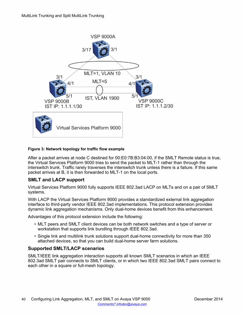
Figure 3: Network topology for traffic flow example
After a packet arrives at node C destined for 00:E0:7B:B3:04:00, if the SMLT Remote status is true,the Virtual Services Platform 9000 tries to send the packet to MLT-1 rather than through theinterswitch trunk. Traffic rarely traverses the interswitch trunk unless there is a failure. If this samepacket arrives at B, it is then forwarded to MLT-1 on the local ports.
SMLT and LACP supportVirtual Services Platform 9000 fully supports IEEE 802.3ad LACP on MLTs and on a pair of SMLTsystems.
With LACP the Virtual Services Platform 9000 provides a standardized external link aggregationinterface to third-party vendor IEEE 802.3ad implementations. This protocol extension providesdynamic link aggregation mechanisms. Only dual-home devices benefit from this enhancement.
Advantages of this protocol extension include the following:
• MLT peers and SMLT client devices can be both network switches and a type of server orworkstation that supports link bundling through IEEE 802.3ad.
• Single link and multilink trunk solutions support dual-home connectivity for more than 350attached devices, so that you can build dual-home server farm solutions.
Supported SMLT/LACP scenariosSMLT/IEEE link aggregation interaction supports all known SMLT scenarios in which an IEEE802.3ad SMLT pair connects to SMLT clients, or in which two IEEE 802.3ad SMLT pairs connect toeach other in a square or full-mesh topology.
MultiLink Trunking and Split MultiLink Trunking
40 Configuring Link Aggregation, MLT, and SMLT on Avaya VSP 9000 December 2014Comments? [email protected]
Unsupported SMLT/LACP scenariosSome of the unsupported SMLT/LACP scenarios include the following factors, which lead to failure:
• Incorrect port connections.• Mismatched MLT IDs assigned to SMLT client. SMLT switches can detect if MLT IDs are not
consistent. The SMLT aggregation switch, which has the lower IP address, does not allow theSMLT port to become a member of the aggregation thereby avoiding misconfigurations.
• The SMLT client switch does not have automatic aggregation enabled (LACP disabled). SMLTaggregation switches can detect that aggregation is not enabled on the SMLT client, thus noautomatic link aggregation is established until the configuration is resolved.
• Single CP module failures. In the case of a CP module failure in a system with only one CPmodule, the LACP on the other switch (or switches) detects the remote failure and triggersremoval of links connected to the failed system from the LAG. This process for failure recoveryfor the network sends the data along a different network path.
• Link Aggregation Control Protocol (LACP) is not supported on Split Multilink Trunking (SMLT)Shortest Path Bridging MAC (SPBM) Network Node Interfaces (NNIs) port type because it cancause traffic to be silently dropped.
SMLT and IP routingThis section describes SMLT and IP routing interactions.
• SMLT and the Virtual Router Redundancy Protocol on page 41• SMLT and VRRP BackupMaster on page 41
SMLT and the Virtual Router Redundancy ProtocolUse Virtual Router Redundancy Protocol (VRRP) to have one active primary router for each IPsubnet, with all other network VRRP interfaces operating in backup mode.
The VRRP has only one active routing interface enabled. Users that access switches aggregatedinto two SMLT switches send their shared traffic load (based on source and destination MAC or IPaddresses) on all uplinks towards the SMLT aggregation switches.
Note:Avaya does not support a VRRP virtual IP address to be the same as the local physical addressof the device.
The VRRP is less efficient if you use it with SMLT. All other interfaces are in backup (standby)mode. In this case, all traffic is forwarded over the IST link towards the primary VRRP switch. Alltraffic that arrives at the VRRP backup interface is forwarded, so there is not enough bandwidth onthe IST link to carry all the aggregated riser traffic. However, an enhancement to VRRP overcomesthis issue by ensuring that the IST trunk is not used in such a case for primary data forwarding.
SMLT and VRRP BackupMasterThe VRRP BackupMaster acts as an IP router for packets destined for the logical VRRP IP address.The system directly routes all traffic to the destined subnetwork and not through Layer 2 switches tothe VRRP master. This avoids a potential limitation in the available IST bandwidth.
To avoid potential frame duplication problems, you can only use the VRRP BackupMaster featurefor SMLT on interfaces that you configure for SMLT. You cannot use VRRP BackupMaster withhubs to avoid frame duplication or on brouter or VLAN interfaces.
Split MultiLink Trunking
December 2014 Configuring Link Aggregation, MLT, and SMLT on Avaya VSP 9000 41Comments? [email protected]
If you use an SMLT with routing on SMLT aggregation switches, Avaya recommends that you useVRRP for default gateway redundancy. In a VRRP environment, one switch is active and the otheris a backup. In an SMLT environment, you can enable the VRRP BackupMaster and use an active-active concept. The VRRP BackupMaster router routes traffic that is received on the SMLT VLANand avoids traffic flow across the IST. This provides true load-sharing abilities.
The BackupMaster feature provides an additional benefit. Virtual Router Redundancy Protocolnormally sends a hello packet every second. After three hello packets are not received, all switchesautomatically revert to master mode. This results in a 3-second outage. If you use VRRP in anSMLT environment, and a link goes down, the system automatically forwards traffic to the remainingports that you configure as SMLT VRRP BackupMaster. Because both systems process traffic, thenode immediately recognizes the VRRP state change, so there is faster failure recovery (less than 1second).
Follow these guidelines if you use VRRP BackupMaster with SMLT:
• The VRRP virtual IP address and the VLAN IP address cannot be the same.• Configure the hold-down timer for VRRP to a value that is approximately one hundred and fifty
percent of the Interior Gateway Protocol (IGP) convergence time to allow the IGP enough timeto reconverge following a failure. For example, if OSPF takes 40 seconds to reconverge,configure the hold-down timer to 60 seconds.
• Stagger the hold-down timers with ARP requests so the Virtual Services Platform 9000 doesnot run ARP and SMLT at the same time causing excess CPU load. For example, if one nodehas the hold-down timer configured for 60 seconds, you can configure the other hold-downtimer to 65 seconds.
• Enable hold-down times on both VRRP sides (Master and BackupMaster).
SMLT and SLPPYou can use Simple Loop Prevention Protocol (SLPP) to prevent loops in an SMLT network. SLPPfocuses on SMLT networks but works with other configurations. Avaya recommends that you alwaysuse SLPP in an SMLT environment.
For square and full-mesh configurations that use a routed core, Avaya recommends that you createa separate core VLAN. Enable SLPP on the core VLAN and the square or full mesh links betweenswitch clusters. This configuration detects loops created in the core and loops at the edge do notaffect core ports. If you use RSMLT between the switch clusters, enable SLPP on the RSMLTVLAN. Because you enable SLPP only on one or two VLANs in the core, changing the RX thresholdvalues will not be necessary.
The Virtual Services Platform 9000 does not support SLPP in an SMLT that uses LACP.
The SLPP design is to shutdown the port where the SLPP packets originate or to shutdown the ISTpeer switch port, after the counter reaches the threshold. A loop can still occur after ports areshutdown. SLPP can shutdown all SMLT ports on a triangle SMLT topology, which results inisolating the edge switch.
For more information about SLPP fundamentals and configuration, see Configuring VLANs andSpanning Tree on Avaya Virtual Services Platform 9000, NN46250-500.
MultiLink Trunking and Split MultiLink Trunking
42 Configuring Link Aggregation, MLT, and SMLT on Avaya VSP 9000 December 2014Comments? [email protected]
MLT and SMLT configuration considerationsUse the information in this section to understand the considerations and guidelines while configuringlink aggregation into your network.
MLT with LACP configuration considerationsAfter you configure MLT with LACP, you must enable the aggregation parameter. After you enablethe aggregation parameter, the LACP aggregator maps one-to-one to the specified multilink trunk.
The following lists the steps that are involved to configure MLT with LACP:
1. Assign a numeric key to the ports you want to include in the LAG.2. Configure the LAG for aggregation.3. Enable LACP on the port.4. Create an MLT and assign to it the same key as in step 1.
The multilink trunk with LACP only aggregates ports whose key matches its own.
The newly created MLT with LACP adopts the VLAN membership of its member ports after the firstport is attached to the aggregator associated with this LAG. After a port detaches from anaggregator, the associated LAG port deletes the member from its list.
After a multilink trunk is configured with LACP, you cannot add or delete ports manually without firstdisabling LACP. You can add or remove VLANs to an MLT without manually disabling LACP. Whenyou add or remove VLANs from an LACP-enabled MLT, follow the guidelines in Configuring LACPon an MLT on page 49 or Adding a multilink interswitch or LACP trunk on page 56.
To enable tagging on ports belonging to a LAG, disable LACP on the port and then enable taggingand LACP on the port.
If you enable Open Shortest Path First (OSPF) routing on a port, do not set the LACP periodictransmission timer to less than 1 second.
MLT with LACP and SMLT configuration considerationsYou can configure Split MultiLink Trunking (SMLT) with MLT, or with MLT with LACP. Follow theseguidelines while you configure SMLT with LACP:
• If you configure LACP for SMLT, you must configure the same LACP smlt-sys-id on both sides.
After you configure the LACP system ID for SMLT, configure the same LACP smlt-sys-id onboth aggregation switches to avoid loss of data. Avaya recommends that you configure theLACP smlt-sys-id to be the base MAC address of one of the aggregate switches, and that youinclude the MLT-ID. Configure the same system ID on both of the SMLT core aggregationswitches.
• If you use LACP in an SMLT square configuration, the LACP ports must have the same keysfor that SMLT LAG; otherwise, the aggregation can fail if a switch fails.
• If you need to modify the LACP configuration, for example, change the LACP key, on a squareor full-mesh core network, you must perform the following tasks:
1. Shutdown all LACP ports.2. Make the configuration change.3. Bring all LACP ports back up.
MLT and SMLT configuration considerations
December 2014 Configuring Link Aggregation, MLT, and SMLT on Avaya VSP 9000 43Comments? [email protected]
If you only disable LACP without shutting down the LACP ports, you can create a loopingscenario.
• If an SMLT aggregation switch has LACP enabled on some of its multilink trunks, do notchange the LACP system priority.
• After you configure SMLT links, Avaya recommends that you set the multicast packets-per-second value to 6000 pps.
• Avaya recommends that you do not enable LACP on ISTs to avoid unnecessary processing.Use VLACP if an optical network between the SMLT core switches requires a failure detectionmechanism.
• Enabling multicast MLT distribution on a square-mesh SMLT can cause loss of streams goingthrough the diagonal links. This results in traffic distributed improperly. Avaya recommends thatyou disable the diagonal links.
Using the LACP smlt-sys-id enables you to use a third-party switch as a wiring closet switch in anSMLT configuration. This enhancement provides an option for the administrator to configure theSMLT Core Aggregation Switches to always use the system ID. In this way, the SMLT CoreAggregation Switch always uses the same LACP key regardless of the state of the SMLT CoreAggregation Switch neighbor (or the IST link). Therefore no change in LAGs must occur on theattached device regardless of whether the device is a server or a third-party switch. This situationdoes not affect Avaya edge switches used in SMLT configurations. The actor system priority ofLACP_DEFAULT_SYS_PRIO, the actor system ID the user configures, and an actor key equal tothe MLT-ID are sent to the wiring closet switch. Avaya recommends that you configure the systemID to be the base MAC address of one of the aggregate switches along with its MLT-ID. Theadministrator must ensure that the same value for the system ID is configured on both of the SMLTCore Aggregation Switches.
The Virtual Services Platform 9000 software does not support Simple Loop Prevention Protocol(SLPP) in an LACP-SMLT environment.
You can configure the LACP smlt-sys-id used by SMLT core aggregation switches. After you set theLACP system ID for SMLT, configure the same LACP smlt-sys-id on both aggregation switches toavoid the loss of data.
The LACP System ID is the base MAC address of the switch, which is carried in Link AggregationControl Protocol Data Units (LACPDU). If two links interconnect two switches that run LACP, eachswitch knows that both links connect to the same remote device because the LACPDUs originatefrom the same System ID. If you enable the links for aggregation using the same key, LACP candynamically aggregate them into an MLT LAG.
If SMLT is used between the two switches, they act as one logical switch. Both aggregationswitches must use the same LACP System ID over the SMLT links so that the edge switch sees onelogical LACP peer, and can aggregate uplinks towards the SMLT aggregation switches. Thisprocess automatically occurs over the IST connection, where the base MAC address of one of theSMLT aggregation switches is chosen and used by both SMLT aggregation switches.
However, if the switch that owns that Base MAC address restarts, the IST goes down, and the otherswitch reverts to using its own Base MAC address as the LACP System ID. This action causes alledge switches that run LACP to think that their links are connected to a different switch. The edgeswitches stop forwarding traffic on their remaining uplinks until the aggregation can reform (whichcan take several seconds). Additionally, after the restarted switch comes back on line, the sameactions occur, thus disrupting traffic twice.
MultiLink Trunking and Split MultiLink Trunking
44 Configuring Link Aggregation, MLT, and SMLT on Avaya VSP 9000 December 2014Comments? [email protected]
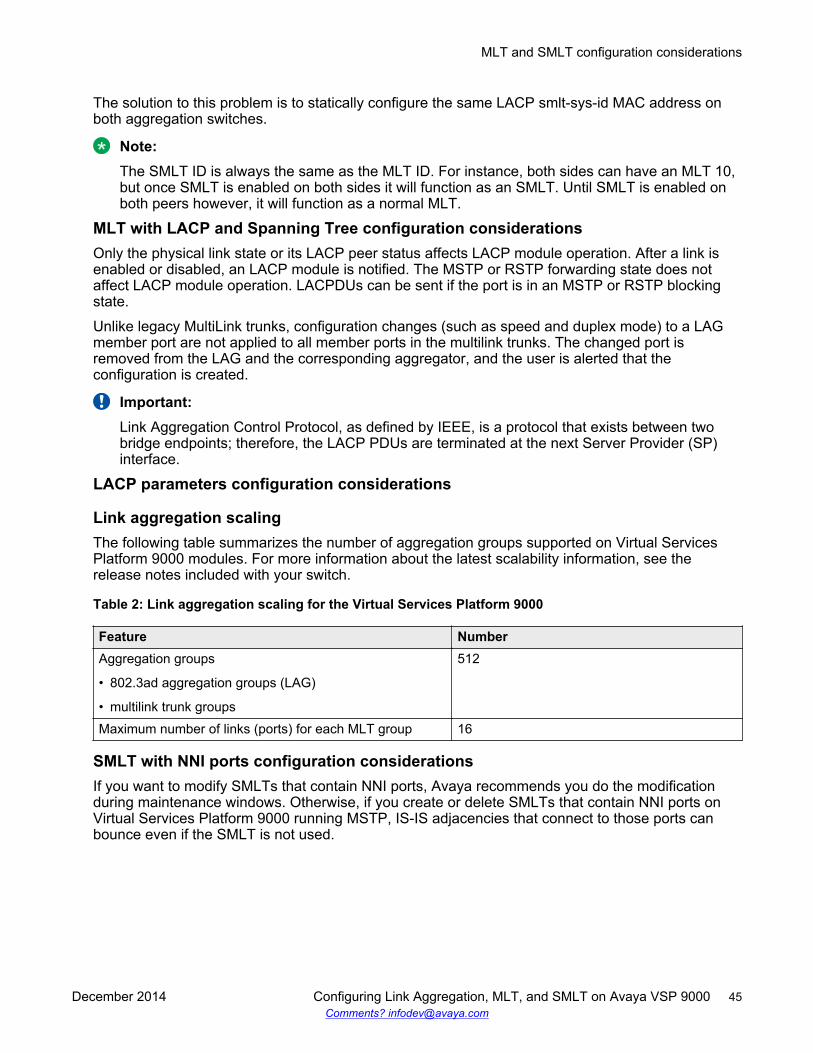
The solution to this problem is to statically configure the same LACP smlt-sys-id MAC address onboth aggregation switches.
Note:The SMLT ID is always the same as the MLT ID. For instance, both sides can have an MLT 10,but once SMLT is enabled on both sides it will function as an SMLT. Until SMLT is enabled onboth peers however, it will function as a normal MLT.
MLT with LACP and Spanning Tree configuration considerationsOnly the physical link state or its LACP peer status affects LACP module operation. After a link isenabled or disabled, an LACP module is notified. The MSTP or RSTP forwarding state does notaffect LACP module operation. LACPDUs can be sent if the port is in an MSTP or RSTP blockingstate.
Unlike legacy MultiLink trunks, configuration changes (such as speed and duplex mode) to a LAGmember port are not applied to all member ports in the multilink trunks. The changed port isremoved from the LAG and the corresponding aggregator, and the user is alerted that theconfiguration is created.
Important:Link Aggregation Control Protocol, as defined by IEEE, is a protocol that exists between twobridge endpoints; therefore, the LACP PDUs are terminated at the next Server Provider (SP)interface.
LACP parameters configuration considerations
Link aggregation scalingThe following table summarizes the number of aggregation groups supported on Virtual ServicesPlatform 9000 modules. For more information about the latest scalability information, see therelease notes included with your switch.
Table 2: Link aggregation scaling for the Virtual Services Platform 9000
Feature NumberAggregation groups
• 802.3ad aggregation groups (LAG)
• multilink trunk groups
512
Maximum number of links (ports) for each MLT group 16
SMLT with NNI ports configuration considerationsIf you want to modify SMLTs that contain NNI ports, Avaya recommends you do the modificationduring maintenance windows. Otherwise, if you create or delete SMLTs that contain NNI ports onVirtual Services Platform 9000 running MSTP, IS-IS adjacencies that connect to those ports canbounce even if the SMLT is not used.
MLT and SMLT configuration considerations
December 2014 Configuring Link Aggregation, MLT, and SMLT on Avaya VSP 9000 45Comments? [email protected]
MLT and SMLT link aggregation configuration using theACLI
This section describes how to configure and manage link aggregation using the ACLI, includingMultiLinkTrunking (MLT), to increase the link speed and redundancy for higher availability.
Configure link aggregation to provide link level redundancy and increase load sharing. MultiLinkTrunking (MLT) is a link aggregation technology that you can use to group several physical Ethernetlinks into one logical Ethernet link to provide fault-tolerance and high-speed links between routers,switches, and servers. Split MultiLink Trunking (SMLT) is an option that improves Layer 2 (bridged)resiliency.
For more advanced configuration information, see Switch Clustering using Split Multi-Link Trunking(SMLT) with VSP 9000, ERS 8600/8800, 8300, and 5000 Technical Configuration Guide(NN48500-518). For more information about the technical configuration guide, go to the Avaya Website: http://support.avaya.com.
Configuring an MLTPerform this procedure to create and configure an MLT.
Procedure1. Log on to Global Configuration mode:
enableconfigure terminal
2. Create an MLT:
mlt <1-512>3. Add a VLAN to the MLT:
mlt <1-512> vlan <1-4084>4. Optionally, change the name of the MLT:
mlt <1-512> name WORD<0-20>5. Enable trunking on the MLT:
mlt <1-512> encapsulation dot1q6. Enable the MLT:
mlt <1-512> enable7. Display the MLT configuration:
show mlt <1–512>
MultiLink Trunking and Split MultiLink Trunking
46 Configuring Link Aggregation, MLT, and SMLT on Avaya VSP 9000 December 2014Comments? [email protected]
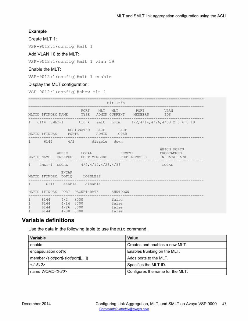
ExampleCreate MLT 1:VSP-9012:1(config)#mlt 1Add VLAN 10 to the MLT:VSP-9012:1(config)#mlt 1 vlan 19Enable the MLT:VSP-9012:1(config)#mlt 1 enableDisplay the MLT configuration:VSP-9012:1(config)#show mlt 1================================================================================ Mlt Info================================================================================ PORT MLT MLT PORT VLANMLTID IFINDEX NAME TYPE ADMIN CURRENT MEMBERS IDS--------------------------------------------------------------------------------1 6144 SMLT-1 trunk smlt norm 4/2,4/14,4/26,4/38 2 3 4 6 19
DESIGNATED LACP LACPMLTID IFINDEX PORTS ADMIN OPER--------------------------------------------------------------------------------1 6144 4/2 disable down
WHICH PORTS WHERE LOCAL REMOTE PROGRAMMEDMLTID NAME CREATED PORT MEMBERS PORT MEMBERS IN DATA PATH--------------------------------------------------------------------------------1 SMLT-1 LOCAL 4/2,4/14,4/26,4/38 LOCAL
ENCAPMLTID IFINDEX DOT1Q LOSSLESS--------------------------------------------------------------------------------1 6144 enable disable
MLTID IFINDEX PORT PACKET-RATE SHUTDOWN--------------------------------------------------------------------------------1 6144 4/2 8000 false1 6144 4/14 8000 false1 6144 4/26 8000 false1 6144 4/38 8000 false
Variable definitionsUse the data in the following table to use the mlt command.
Variable Valueenable Creates and enables a new MLT.encapsulation dot1q Enables trunking on the MLT.member {slot/port[-slot/port][,...]} Adds ports to the MLT.<1-512> Specifies the MLT ID.name WORD<0-20> Configures the name for the MLT.
MLT and SMLT link aggregation configuration using the ACLI
December 2014 Configuring Link Aggregation, MLT, and SMLT on Avaya VSP 9000 47Comments? [email protected]
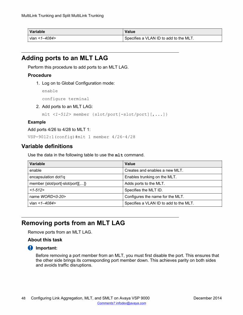
Variable Valuevlan <1–4084> Specifies a VLAN ID to add to the MLT.
Adding ports to an MLT LAGPerform this procedure to add ports to an MLT LAG.
Procedure1. Log on to Global Configuration mode:
enableconfigure terminal
2. Add ports to an MLT LAG:
mlt <1-512> member {slot/port[-slot/port][,...]}ExampleAdd ports 4/26 to 4/28 to MLT 1:VSP-9012:1(config)#mlt 1 member 4/26–4/28
Variable definitionsUse the data in the following table to use the mlt command.
Variable Valueenable Creates and enables a new MLT.encapsulation dot1q Enables trunking on the MLT.member {slot/port[-slot/port][,...]} Adds ports to the MLT.<1-512> Specifies the MLT ID.name WORD<0-20> Configures the name for the MLT.vlan <1–4084> Specifies a VLAN ID to add to the MLT.
Removing ports from an MLT LAGRemove ports from an MLT LAG.
About this taskImportant:Before removing a port member from an MLT, you must first disable the port. This ensures thatthe other side brings its corresponding port member down. This achieves parity on both sidesand avoids traffic disruptions.
MultiLink Trunking and Split MultiLink Trunking
48 Configuring Link Aggregation, MLT, and SMLT on Avaya VSP 9000 December 2014Comments? [email protected]
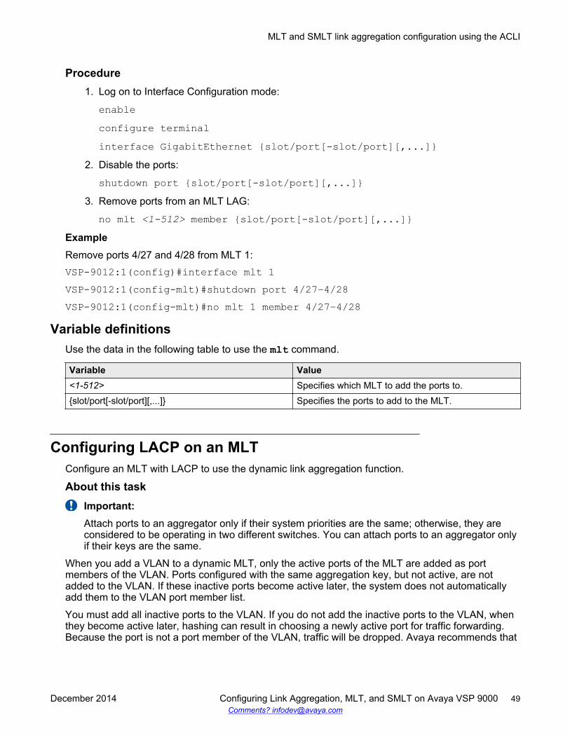
Procedure1. Log on to Interface Configuration mode:
enableconfigure terminalinterface GigabitEthernet {slot/port[-slot/port][,...]}
2. Disable the ports:
shutdown port {slot/port[-slot/port][,...]}3. Remove ports from an MLT LAG:
no mlt <1-512> member {slot/port[-slot/port][,...]}ExampleRemove ports 4/27 and 4/28 from MLT 1:VSP-9012:1(config)#interface mlt 1VSP-9012:1(config-mlt)#shutdown port 4/27–4/28VSP-9012:1(config-mlt)#no mlt 1 member 4/27–4/28
Variable definitionsUse the data in the following table to use the mlt command.
Variable Value<1-512> Specifies which MLT to add the ports to.{slot/port[-slot/port][,...]} Specifies the ports to add to the MLT.
Configuring LACP on an MLTConfigure an MLT with LACP to use the dynamic link aggregation function.
About this taskImportant:Attach ports to an aggregator only if their system priorities are the same; otherwise, they areconsidered to be operating in two different switches. You can attach ports to an aggregator onlyif their keys are the same.
When you add a VLAN to a dynamic MLT, only the active ports of the MLT are added as portmembers of the VLAN. Ports configured with the same aggregation key, but not active, are notadded to the VLAN. If these inactive ports become active later, the system does not automaticallyadd them to the VLAN port member list.
You must add all inactive ports to the VLAN. If you do not add the inactive ports to the VLAN, whenthey become active later, hashing can result in choosing a newly active port for traffic forwarding.Because the port is not a port member of the VLAN, traffic will be dropped. Avaya recommends that
MLT and SMLT link aggregation configuration using the ACLI
December 2014 Configuring Link Aggregation, MLT, and SMLT on Avaya VSP 9000 49Comments? [email protected]
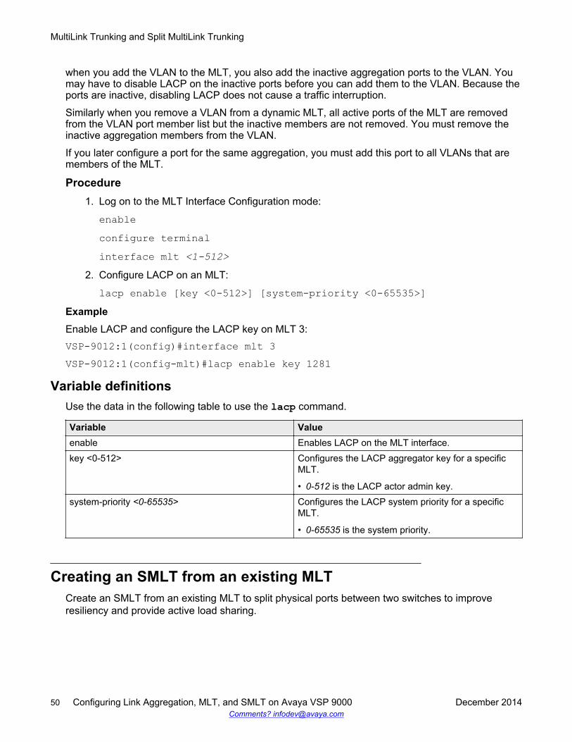
when you add the VLAN to the MLT, you also add the inactive aggregation ports to the VLAN. Youmay have to disable LACP on the inactive ports before you can add them to the VLAN. Because theports are inactive, disabling LACP does not cause a traffic interruption.
Similarly when you remove a VLAN from a dynamic MLT, all active ports of the MLT are removedfrom the VLAN port member list but the inactive members are not removed. You must remove theinactive aggregation members from the VLAN.
If you later configure a port for the same aggregation, you must add this port to all VLANs that aremembers of the MLT.
Procedure1. Log on to the MLT Interface Configuration mode:
enableconfigure terminalinterface mlt <1-512>
2. Configure LACP on an MLT:
lacp enable [key <0-512>] [system-priority <0-65535>]ExampleEnable LACP and configure the LACP key on MLT 3:VSP-9012:1(config)#interface mlt 3VSP-9012:1(config-mlt)#lacp enable key 1281
Variable definitionsUse the data in the following table to use the lacp command.
Variable Valueenable Enables LACP on the MLT interface.key <0-512> Configures the LACP aggregator key for a specific
MLT.
• 0-512 is the LACP actor admin key.system-priority <0-65535> Configures the LACP system priority for a specific
MLT.
• 0-65535 is the system priority.
Creating an SMLT from an existing MLTCreate an SMLT from an existing MLT to split physical ports between two switches to improveresiliency and provide active load sharing.
MultiLink Trunking and Split MultiLink Trunking
50 Configuring Link Aggregation, MLT, and SMLT on Avaya VSP 9000 December 2014Comments? [email protected]

Note:
If you want to modify SMLTs that contain NNI ports, Avaya recommends you do the modificationduring maintenance windows. Otherwise, if you create or delete SMLTs that contain NNI portson Virtual Services Platform 9000 running MSTP, IS-IS adjacencies that connect to those portscan bounce even if the SMLT is not used.
Before you begin• Create an MLT before you create a split in the MLT.
Procedure1. Log on to the MLT Interface Configuration mode:
enableconfigure terminalinterface mlt <1-512>
2. Create an SMLT from an existing MLT:
smltExampleCreate an SMLT on MLT 1:VSP-9012:1(config)#interface mlt 1VSP-9012:1(config-mlt)#smlt
Creating an interswitch trunkCreate an interswitch trunk from an existing MLT.
About this taskImportant:Do not enable loop-detect on IST ports.
If you attempt to enable loop-detect on an existing IST port, the system prevents you from doingso. However, if you have a port with loop-detect already enabled, and you add that port to anIST, the system does not prevent you from doing so, causing potential system errors.
Procedure1. Log on to the MLT Interface Configuration mode:
enableconfigure terminalinterface mlt <1-512>
2. Create an interswitch trunk:
MLT and SMLT link aggregation configuration using the ACLI
December 2014 Configuring Link Aggregation, MLT, and SMLT on Avaya VSP 9000 51Comments? [email protected]
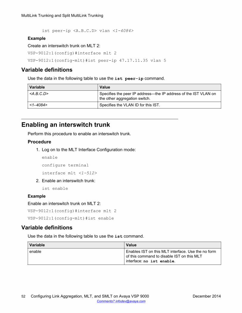
ist peer-ip <A.B.C.D> vlan <1-4084>ExampleCreate an interswitch trunk on MLT 2:VSP-9012:1(config)#interface mlt 2VSP-9012:1(config-mlt)#ist peer-ip 47.17.11.35 vlan 5
Variable definitionsUse the data in the following table to use the ist peer-ip command.
Variable Value<A.B.C.D> Specifies the peer IP address—the IP address of the IST VLAN on
the other aggregation switch.<1–4084> Specifies the VLAN ID for this IST.
Enabling an interswitch trunkPerform this procedure to enable an interswitch trunk.
Procedure1. Log on to the MLT Interface Configuration mode:
enableconfigure terminalinterface mlt <1-512>
2. Enable an interswitch trunk:
ist enableExampleEnable an interswitch trunk on MLT 2:VSP-9012:1(config)#interface mlt 2VSP-9012:1(config-mlt)#ist enable
Variable definitionsUse the data in the following table to use the ist command.
Variable Valueenable Enables IST on this MLT interface. Use the no form
of this command to disable IST on this MLTinterface: no ist enable.
MultiLink Trunking and Split MultiLink Trunking
52 Configuring Link Aggregation, MLT, and SMLT on Avaya VSP 9000 December 2014Comments? [email protected]
Deleting an interswitch trunkDelete an interswitch trunk.
Before you beginImportant:Before you can delete the interswitch trunk, you must disable the interswitch trunk.
Note:The no ist enable command only dynamically disables the IST. The IST will becomeenabled again the next time the chassis reboots. Use the following procedure to permanentlydelete an IST.
Procedure1. Log on to the MLT Interface Configuration mode:
enableconfigure terminalinterface mlt <1-512>
2. Disable an interswitch trunk:
no ist enable3. Delete an interswitch trunk:
no ist peer-ipExampleFrom Global Configuration mode, log on to the MLT interface:VSP-9012:1(config)# interface mlt 2Disable the IST:VSP-9012:1(config)# no ist enableDelete the IST:VSP-9012:1(config)# no ist peer-ip
Viewing the MLT port calculated by the MLT hash algorithmView the MLT port calculated by the MLT hash algorithm to determine through which MLT port apacket will exit the system.
ProcedureView the MLT port calculated by the MLT hash algorithm:
MLT and SMLT link aggregation configuration using the ACLI
December 2014 Configuring Link Aggregation, MLT, and SMLT on Avaya VSP 9000 53Comments? [email protected]
hash-calc getmltindex traffic-type <ipv4|ipv6|non-ip> dest-valWORD<1-1536> src-val WORD<1-1536> mltID <1-512> [src-port <0-65535>][dest-port <0-65535>]The source and destination addresses cannot have the same value.
ExampleView the MLT port calculated by the MLT hash algorithm:VSP-9012:1#hash-cal getmltindex traffic-type ipv4 dest-val 47.17.11.30src-val 47.17.10.31 mltid 1Traffic will egress port 4/26 for this flow for MltId 1
Variable definitionsUse the data in the following table to use the hash-calc getmltindex command.
Variable Valuedest-port <0-65535> Specifies the destination port.dest-val WORD<1-1536> Specifies the destination address. The source and
destination addresses cannot have the same value.mltID <1-512> Specifies the MLT ID. The value ranges from 1–512.src-port <0-65535> Specifies the source port.src-val WORD<1-1536> Specifies the source address. The source and
destination addresses cannot have the same value.traffic-type {ipv4|ipv6|non-ip} Specifies the type of traffic, either ipv4, ipv6, or non-
ip.
Viewing information about collision errorsView information about collision errors to obtain information about collision errors in the specifiedMLT, or for all MLTs.
ProcedureView information about collision errors:
show mlt error collision [<1-512>]ExampleVSP-9012:1(config-mlt)#show mlt error collision 4
================================================================================ Mlt Collision Error================================================================================MLT -----------------COLLISIONS------------ID SINGLE MULTIPLE LATE EXCESSIVE--------------------------------------------------------------------------------4 0 0 0 0
MultiLink Trunking and Split MultiLink Trunking
54 Configuring Link Aggregation, MLT, and SMLT on Avaya VSP 9000 December 2014Comments? [email protected]
Variable definitionsUse the data in the following table to use the show mlt error collision command.
Variable Value<1-512> Specifies the MLT ID. The value ranges from 1–512.
Viewing information about Ethernet errorsView information about Ethernet errors to display information about the types of Ethernet errors sentand received by a specific MLT or all MLTs.
About this taskImportant:The IMAC columns refer to internal MAC address errors.
ProcedureView information about Ethernet errors:
show mlt error main [<1-512>]ExampleVSP-9012:1(config-mlt)#show mlt error main 4
================================================================================ Mlt Ethernet Error================================================================================MLT ALIGN FCS IMAC IMAC CARRIER FRAMES SQETEST DEFERID ERROR ERROR TRNSMIT RECEIVE SENSE TOOLONG ERROR TRNSMSS--------------------------------------------------------------------------------4 0 0 0 0 0 0 0 0
Variable definitionsUse the data in the following table to use the show mlt error main command.
Variable Value<1-512> Specifies the MLT ID. The value ranges from 1–512.
Viewing all ports configured for SMLTView all ports for a SMLT to ensure the correct ports are configured.
ProcedureView all ports configured for Single Port SMLT:
show smlt mlt
MLT and SMLT link aggregation configuration using the ACLI
December 2014 Configuring Link Aggregation, MLT, and SMLT on Avaya VSP 9000 55Comments? [email protected]
ExampleVSP-9012:1(config-mlt)#show smlt mlt
================================================================================ Mlt SMLT Info================================================================================MLT ADMIN CURRENTID TYPE TYPE--------------------------------------------------------------------------------1 smlt smlt4 smlt smlt
Variable definitionsUse the data in the following table to use the show smlt command.
Variable Valuemlt Displays SMLT information for the MLT interface.
MLT and SMLT link aggregation configuration using EDMConfigure link aggregation to provide link level redundancy and increase load sharing. MultiLinkTrunking (MLT) is a link aggregation technology that you can use to group several physical Ethernetlinks into one logical Ethernet link to provide fault-tolerance and high-speed links between routers,switches, and servers. Split MultiLink Trunking (SMLT) is an option that improves Layer 2 (bridged)resiliency.
For more advanced configuration information, see Switch Clustering using Split Multi-Link Trunking(SMLT) with VSP 9000, ERS 8600/8800, 8300, and 5000 Technical Configuration Guide(NN48500-518). For more information about the technical configuration guide, go to the Avaya Website: http://support.avaya.com.
Adding a multilink, interswitch, or LACP trunkPerform this procedure to add a multilink, interswitch, or LACP trunk.
Note:
If you want to modify SMLTs that contain NNI ports, Avaya recommends that you do themodification during maintenance windows. Otherwise, if you create or delete SMLTs thatcontain NNI ports on Virtual Services Platform 9000 running MSTP, IS-IS adjacencies thatconnect to those ports can bounce even if the SMLT is not used.
MultiLink Trunking and Split MultiLink Trunking
56 Configuring Link Aggregation, MLT, and SMLT on Avaya VSP 9000 December 2014Comments? [email protected]
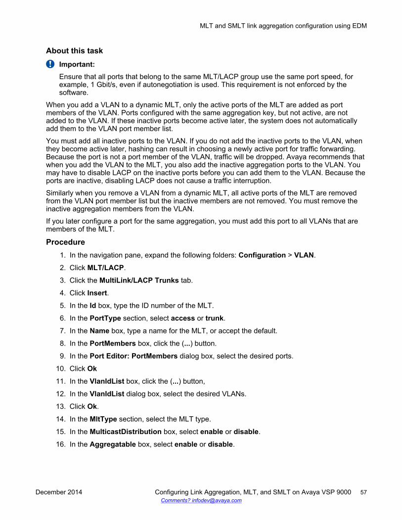
About this taskImportant:Ensure that all ports that belong to the same MLT/LACP group use the same port speed, forexample, 1 Gbit/s, even if autonegotiation is used. This requirement is not enforced by thesoftware.
When you add a VLAN to a dynamic MLT, only the active ports of the MLT are added as portmembers of the VLAN. Ports configured with the same aggregation key, but not active, are notadded to the VLAN. If these inactive ports become active later, the system does not automaticallyadd them to the VLAN port member list.
You must add all inactive ports to the VLAN. If you do not add the inactive ports to the VLAN, whenthey become active later, hashing can result in choosing a newly active port for traffic forwarding.Because the port is not a port member of the VLAN, traffic will be dropped. Avaya recommends thatwhen you add the VLAN to the MLT, you also add the inactive aggregation ports to the VLAN. Youmay have to disable LACP on the inactive ports before you can add them to the VLAN. Because theports are inactive, disabling LACP does not cause a traffic interruption.
Similarly when you remove a VLAN from a dynamic MLT, all active ports of the MLT are removedfrom the VLAN port member list but the inactive members are not removed. You must remove theinactive aggregation members from the VLAN.
If you later configure a port for the same aggregation, you must add this port to all VLANs that aremembers of the MLT.
Procedure1. In the navigation pane, expand the following folders: Configuration > VLAN.
2. Click MLT/LACP.
3. Click the MultiLink/LACP Trunks tab.
4. Click Insert.
5. In the Id box, type the ID number of the MLT.
6. In the PortType section, select access or trunk.
7. In the Name box, type a name for the MLT, or accept the default.
8. In the PortMembers box, click the (...) button.
9. In the Port Editor: PortMembers dialog box, select the desired ports.
10. Click Ok
11. In the VlanIdList box, click the (...) button,
12. In the VlanIdList dialog box, select the desired VLANs.
13. Click Ok.
14. In the MltType section, select the MLT type.
15. In the MulticastDistribution box, select enable or disable.
16. In the Aggregatable box, select enable or disable.
MLT and SMLT link aggregation configuration using EDM
December 2014 Configuring Link Aggregation, MLT, and SMLT on Avaya VSP 9000 57Comments? [email protected]
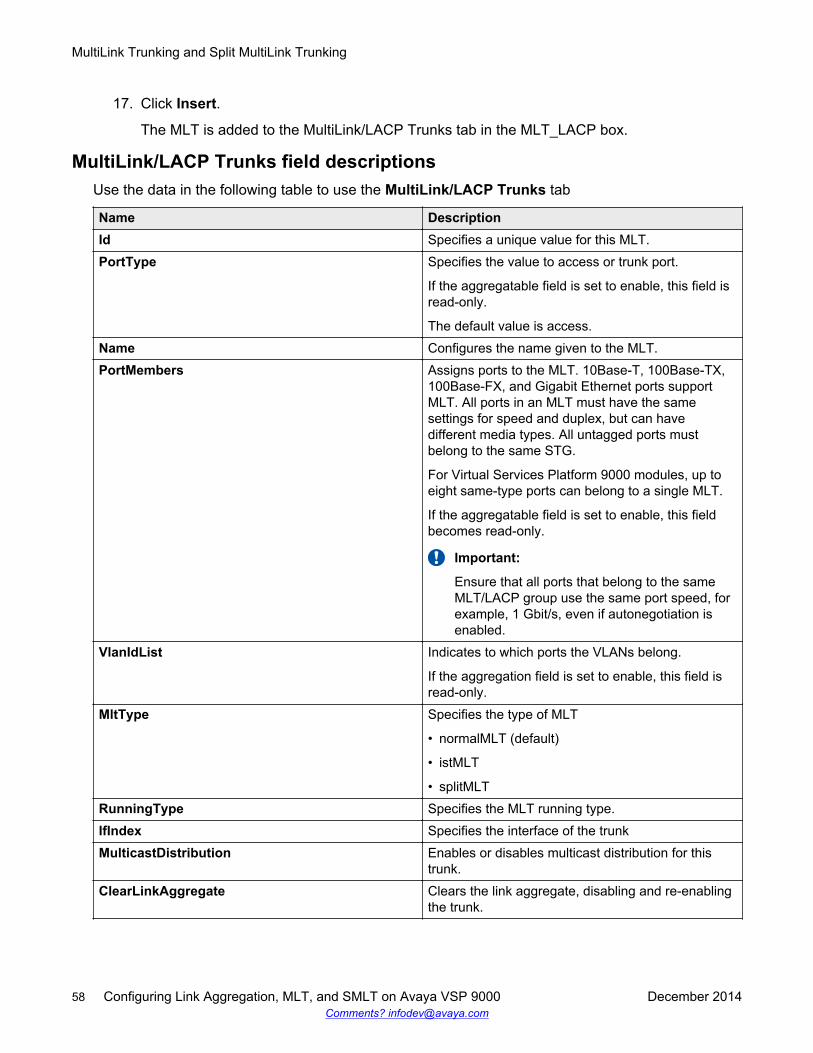
17. Click Insert.
The MLT is added to the MultiLink/LACP Trunks tab in the MLT_LACP box.
MultiLink/LACP Trunks field descriptionsUse the data in the following table to use the MultiLink/LACP Trunks tab
Name DescriptionId Specifies a unique value for this MLT.PortType Specifies the value to access or trunk port.
If the aggregatable field is set to enable, this field isread-only.
The default value is access.Name Configures the name given to the MLT.PortMembers Assigns ports to the MLT. 10Base-T, 100Base-TX,
100Base-FX, and Gigabit Ethernet ports supportMLT. All ports in an MLT must have the samesettings for speed and duplex, but can havedifferent media types. All untagged ports mustbelong to the same STG.
For Virtual Services Platform 9000 modules, up toeight same-type ports can belong to a single MLT.
If the aggregatable field is set to enable, this fieldbecomes read-only.
Important:
Ensure that all ports that belong to the sameMLT/LACP group use the same port speed, forexample, 1 Gbit/s, even if autonegotiation isenabled.
VlanIdList Indicates to which ports the VLANs belong.
If the aggregation field is set to enable, this field isread-only.
MltType Specifies the type of MLT
• normalMLT (default)
• istMLT
• splitMLTRunningType Specifies the MLT running type.IfIndex Specifies the interface of the trunkMulticastDistribution Enables or disables multicast distribution for this
trunk.ClearLinkAggregate Clears the link aggregate, disabling and re-enabling
the trunk.
MultiLink Trunking and Split MultiLink Trunking
58 Configuring Link Aggregation, MLT, and SMLT on Avaya VSP 9000 December 2014Comments? [email protected]

Name DescriptionDesignatedPort Specifies the designated port of this trunk.Aggregatable Enables or disables link aggregation.
The default value is disable.AggOperState Specifies the aggregation state of the trunk.AggTimeOfLastOperChange Specifies the time value since the interface entered
its current operational state.PeerPortMembers Specifies the peer ports connected to the local ports
of this trunk.CpLimitPktRate Limits control packets to QoS levels 6 and 7.
Configures the limit in packets per second.CpLimitShutDownEnable Indicates if the MLT ports shutdown after the value
in CpLimitPktRate is exceeded.EntryOwner Defines the owner of the MLT.DatapathProgrammingState Defines the datapath programming state of the MLT.
Adding ports to an MLTAdd ports to an MLT to insert MultiLink/LACP trunks.
Procedure1. In the navigation pane, expand the following folders: Configuration > VLAN.
2. Click MLT/LACP.
3. Click the MultiLink/LACP Trunks tab.
4. In the PortMembers column, double-click the field associated with the MLT to which youwant to add ports to.
5. Select the port numbers to add, or click All to add all ports to the MLT.
Up to 16 same-type ports can belong to a single MLT.
6. Click Ok.
7. Click Apply.
Viewing trunksPerform this procedure to view the MLT-based SMLT configuration.
Procedure1. In the navigation pane, expand the following folders: Configuration > VLAN.
2. Click SMLT.
MLT and SMLT link aggregation configuration using EDM
December 2014 Configuring Link Aggregation, MLT, and SMLT on Avaya VSP 9000 59Comments? [email protected]
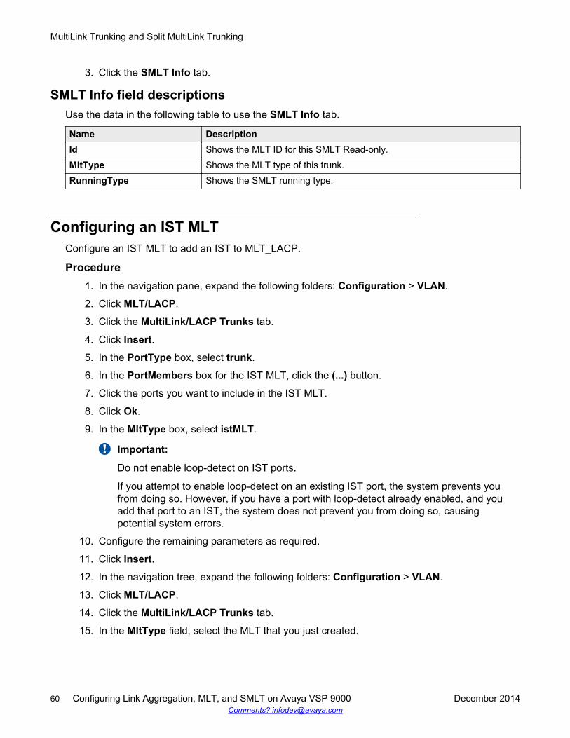
3. Click the SMLT Info tab.
SMLT Info field descriptionsUse the data in the following table to use the SMLT Info tab.
Name DescriptionId Shows the MLT ID for this SMLT Read-only.MltType Shows the MLT type of this trunk.RunningType Shows the SMLT running type.
Configuring an IST MLTConfigure an IST MLT to add an IST to MLT_LACP.
Procedure1. In the navigation pane, expand the following folders: Configuration > VLAN.
2. Click MLT/LACP.
3. Click the MultiLink/LACP Trunks tab.
4. Click Insert.
5. In the PortType box, select trunk.
6. In the PortMembers box for the IST MLT, click the (...) button.
7. Click the ports you want to include in the IST MLT.
8. Click Ok.
9. In the MltType box, select istMLT.
Important:
Do not enable loop-detect on IST ports.
If you attempt to enable loop-detect on an existing IST port, the system prevents youfrom doing so. However, if you have a port with loop-detect already enabled, and youadd that port to an IST, the system does not prevent you from doing so, causingpotential system errors.
10. Configure the remaining parameters as required.
11. Click Insert.
12. In the navigation tree, expand the following folders: Configuration > VLAN.
13. Click MLT/LACP.
14. Click the MultiLink/LACP Trunks tab.
15. In the MltType field, select the MLT that you just created.
MultiLink Trunking and Split MultiLink Trunking
60 Configuring Link Aggregation, MLT, and SMLT on Avaya VSP 9000 December 2014Comments? [email protected]
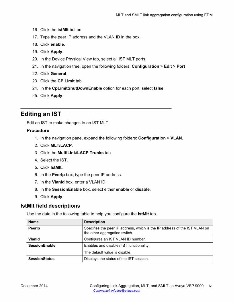
16. Click the istMlt button.
17. Type the peer IP address and the VLAN ID in the box.
18. Click enable.
19. Click Apply.
20. In the Device Physical View tab, select all IST MLT ports.
21. In the navigation tree, open the following folders: Configuration > Edit > Port
22. Click General.
23. Click the CP Limit tab.
24. In the CpLimitShutDownEnable option for each port, select false.
25. Click Apply.
Editing an ISTEdit an IST to make changes to an IST MLT.
Procedure1. In the navigation pane, expand the following folders: Configuration > VLAN.
2. Click MLT/LACP.
3. Click the MultiLink/LACP Trunks tab.
4. Select the IST.
5. Click IstMlt.
6. In the PeerIp box, type the peer IP address.
7. In the VlanId box, enter a VLAN ID.
8. In the SessionEnable box, select either enable or disable.
9. Click Apply.
IstMlt field descriptionsUse the data in the following table to help you configure the IstMlt tab.
Name DescriptionPeerIp Specifies the peer IP address, which is the IP address of the IST VLAN on
the other aggregation switch.VlanId Configures an IST VLAN ID number.SessionEnable Enables and disables IST functionality.
The default value is disable.SessionStatus Displays the status of the IST session.
MLT and SMLT link aggregation configuration using EDM
December 2014 Configuring Link Aggregation, MLT, and SMLT on Avaya VSP 9000 61Comments? [email protected]
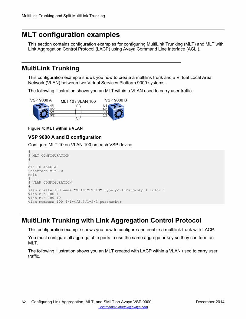
MLT configuration examplesThis section contains configuration examples for configuring MultiLink Trunking (MLT) and MLT withLink Aggregation Control Protocol (LACP) using Avaya Command Line Interface (ACLI).
MultiLink TrunkingThis configuration example shows you how to create a multilink trunk and a Virtual Local AreaNetwork (VLAN) between two Virtual Services Platform 9000 systems.
The following illustration shows you an MLT within a VLAN used to carry user traffic.
Figure 4: MLT within a VLAN
VSP 9000 A and B configurationConfigure MLT 10 on VLAN 100 on each VSP device.## MLT CONFIGURATION#
mlt 10 enableinterface mlt 10exit## VLAN CONFIGURATION#vlan create 100 name "VLAN-MLT-10" type port-mstprstp 1 color 1vlan mlt 100 1vlan mlt 100 10vlan members 100 4/1-4/2,5/1-5/2 portmember
MultiLink Trunking with Link Aggregation Control ProtocolThis configuration example shows you how to configure and enable a multilink trunk with LACP.
You must configure all aggregatable ports to use the same aggregator key so they can form anMLT.
The following illustration shows you an MLT created with LACP within a VLAN used to carry usertraffic.
MultiLink Trunking and Split MultiLink Trunking
62 Configuring Link Aggregation, MLT, and SMLT on Avaya VSP 9000 December 2014Comments? [email protected]
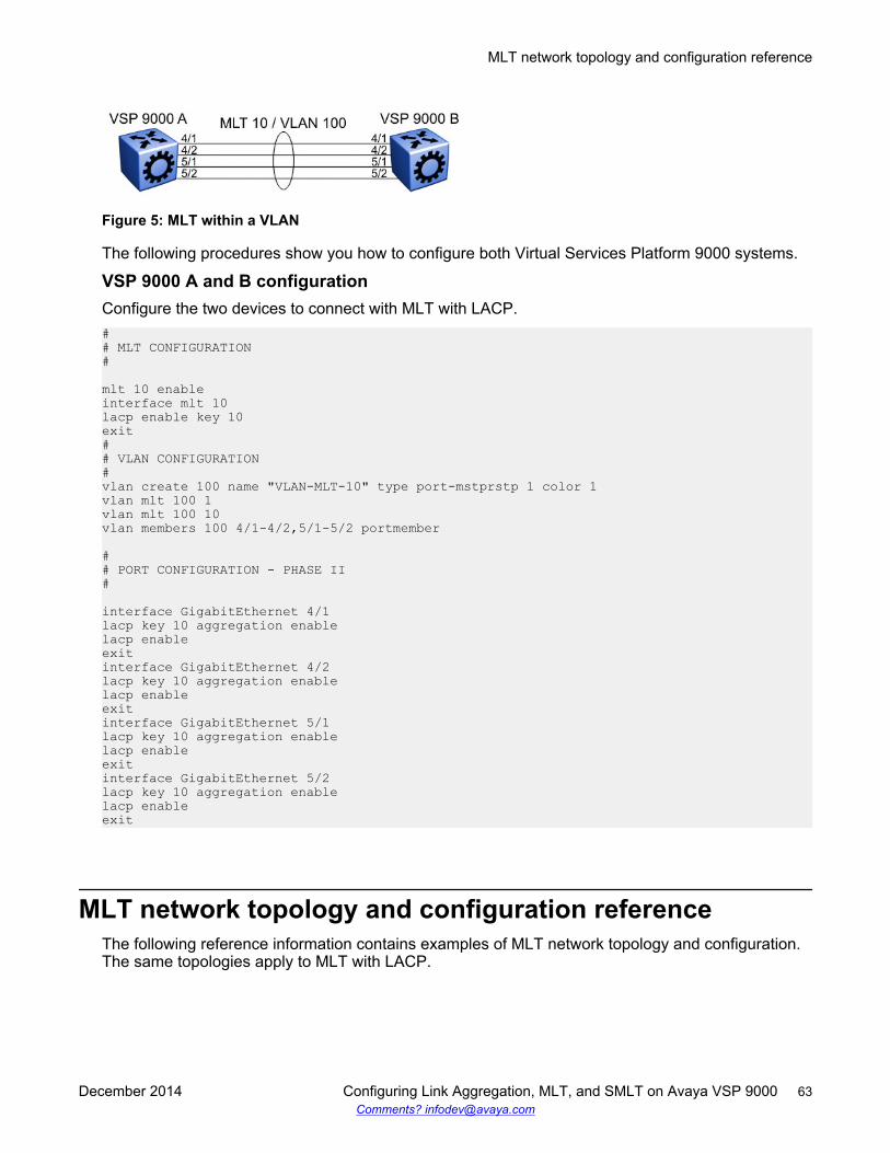
Figure 5: MLT within a VLAN
The following procedures show you how to configure both Virtual Services Platform 9000 systems.
VSP 9000 A and B configurationConfigure the two devices to connect with MLT with LACP.## MLT CONFIGURATION#
mlt 10 enableinterface mlt 10lacp enable key 10exit## VLAN CONFIGURATION#vlan create 100 name "VLAN-MLT-10" type port-mstprstp 1 color 1vlan mlt 100 1vlan mlt 100 10vlan members 100 4/1-4/2,5/1-5/2 portmember
## PORT CONFIGURATION - PHASE II#
interface GigabitEthernet 4/1lacp key 10 aggregation enablelacp enableexitinterface GigabitEthernet 4/2lacp key 10 aggregation enablelacp enableexitinterface GigabitEthernet 5/1lacp key 10 aggregation enablelacp enableexitinterface GigabitEthernet 5/2lacp key 10 aggregation enablelacp enableexit
MLT network topology and configuration referenceThe following reference information contains examples of MLT network topology and configuration.The same topologies apply to MLT with LACP.
MLT network topology and configuration reference
December 2014 Configuring Link Aggregation, MLT, and SMLT on Avaya VSP 9000 63Comments? [email protected]
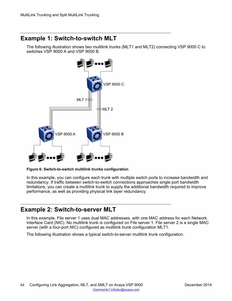
Example 1: Switch-to-switch MLTThe following illustration shows two multilink trunks (MLT1 and MLT2) connecting VSP 9000 C toswitches VSP 9000 A and VSP 9000 B.
Figure 6: Switch-to-switch multilink trunks configuration
In this example, you can configure each trunk with multiple switch ports to increase bandwidth andredundancy. If traffic between switch-to-switch connections approaches single port bandwidthlimitations, you can create a multilink trunk to supply the additional bandwidth required to improveperformance, as well as providing physical link layer redundancy.
Example 2: Switch-to-server MLTIn this example, File server 1 uses dual MAC addresses, with one MAC address for each NetworkInterface Card (NIC). No multilink trunk is configured on File server 1. File server 2 is a single MACserver (with a four-port NIC) configured as multilink trunk configuration MLT1.
The following illustration shows a typical switch-to-server multilink trunk configuration.
MultiLink Trunking and Split MultiLink Trunking
64 Configuring Link Aggregation, MLT, and SMLT on Avaya VSP 9000 December 2014Comments? [email protected]
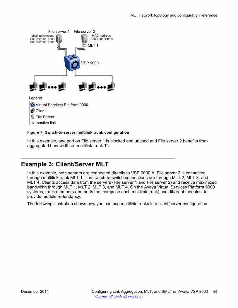
Figure 7: Switch-to-server multilink trunk configuration
In this example, one port on File server 1 is blocked and unused and File server 2 benefits fromaggregated bandwidth on multilink trunk T1.
Example 3: Client/Server MLTIn this example, both servers are connected directly to VSP 9000 A. File server 2 is connectedthrough multilink trunk MLT 1. The switch-to-switch connections are through MLT 2, MLT 3, andMLT 4. Clients access data from the servers (File server 1 and File server 2) and receive maximizedbandwidth through MLT 1, MLT 2, MLT 3, and MLT 4. On the Avaya Virtual Services Platform 9000systems, trunk members (the ports that comprise each multilink trunk) use different modules, toprovide module redundancy.
The following illustration shows how you can use multilink trunks in a client/server configuration.
MLT network topology and configuration reference
December 2014 Configuring Link Aggregation, MLT, and SMLT on Avaya VSP 9000 65Comments? [email protected]
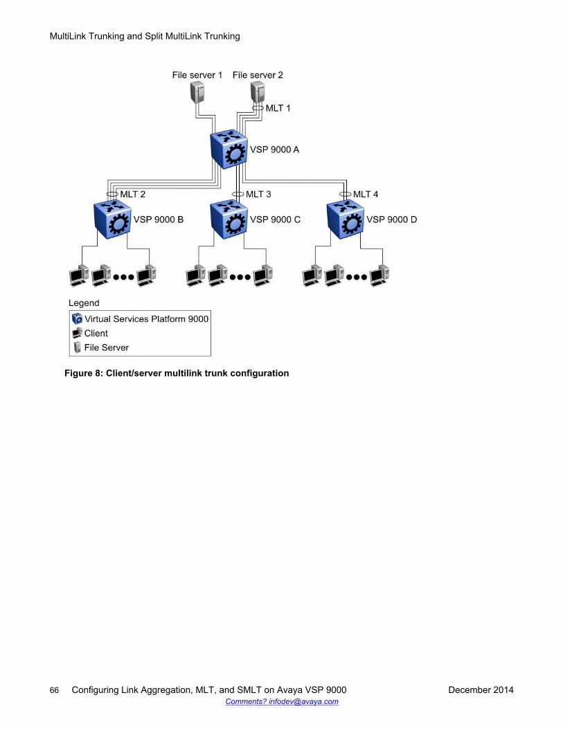
Figure 8: Client/server multilink trunk configuration
MultiLink Trunking and Split MultiLink Trunking
66 Configuring Link Aggregation, MLT, and SMLT on Avaya VSP 9000 December 2014Comments? [email protected]
Chapter 5: Virtual Link Aggregation ControlProtocol
This section provides the concepts and procedures you need to configure the Virtual LinkAggregation Control Protocol (VLACP).
Virtual Link Aggregation Control ProtocolUse Virtual Link Aggregation Control Protocol (VLACP) as an extension to LACP for end-to-endfailure detection. VLACP is not a link aggregation protocol, it is a mechanism to periodically checkthe end-to-end health of a point-to-point connection. VLACP uses the Hello mechanism of LACP toperiodically send Hello packets to ensure end-to-end communication. After Hello packets are notreceived, VLACP transitions to a failure state, which indicates a service provider failure and that theport is disabled.
The VLACP only works for port-to-port communications where there is a guarantee for a logical port-to-port match through the service provider. VLACP does not work for port-to-multiportcommunications where there is no guarantee for a point-to-point match through the service provider.You can configure VLACP on a port.
You can also use VLACP with MLT to complement its capabilities and provide quick failuredetection. Avaya recommends VLACP for all SMLT access links after you configure the links asMLT to ensure both end devices are able to communicate.
VLACP trap messages are sent to the management stations if the VLACP state changes. If thefailure is local, the only traps that are generated are port linkdown or port linkup.
The Ethernet cannot detect end-to-end failures. Functions such as remote fault indication or far-endfault indication extend the Ethernet to detect remote link failures. A major limitation of thesefunctions is that they terminate at the next Ethernet hop. They cannot determine failures on an end-to-end basis.
For example, in Figure 9: Problem description (1 of 2) on page 68, after the Enterprise networksconnect the aggregated Ethernet trunk groups through a service provider network connection (forexample, through a VPN), far-end failures cannot be signaled with Ethernet-based functions thatoperate end-to-end through the service provider network. The multilink trunk (between Enterpriseswitches S1 and S2) extends through the Service Provider (SP) network.
The following illustration shows an MLT running with VLACP. VLACP can operate end-to-end, butyou can also use it as a point-to-point link.
December 2014 Configuring Link Aggregation, MLT, and SMLT on Avaya VSP 9000 67Comments? [email protected]
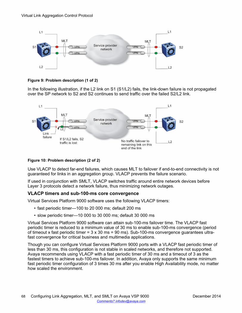
Figure 9: Problem description (1 of 2)
In the following illustration, if the L2 link on S1 (S1/L2) fails, the link-down failure is not propagatedover the SP network to S2 and S2 continues to send traffic over the failed S2/L2 link.
Figure 10: Problem description (2 of 2)
Use VLACP to detect far-end failures, which causes MLT to failover if end-to-end connectivity is notguaranteed for links in an aggregation group. VLACP prevents the failure scenario.
If used in conjunction with SMLT, VLACP switches traffic around entire network devices beforeLayer 3 protocols detect a network failure, thus minimizing network outages.
VLACP timers and sub-100-ms core convergenceVirtual Services Platform 9000 software uses the following VLACP timers:
• fast periodic timer—100 to 20 000 ms; default 200 ms• slow periodic timer—10 000 to 30 000 ms; default 30 000 ms
Virtual Services Platform 9000 software can attain sub-100-ms failover time. The VLACP fastperiodic timer is reduced to a minimum value of 30 ms to enable sub-100-ms convergence (periodof timeout x fast periodic timer = 3 x 30 ms = 90 ms). Sub-100-ms convergence guarantees ultra-fast convergence for critical business and multimedia applications.
Though you can configure Virtual Services Platform 9000 ports with a VLACP fast periodic timer ofless than 30 ms, this configuration is not stable in scaled networks, and therefore not supported.Avaya recommends using VLACP with a fast periodic timer of 30 ms and a timeout of 3 as thefastest timers to achieve sub-100-ms failover. In addition, Avaya only supports the same minimumfast periodic timer configuration of 3 times 30 ms after you enable High Availability mode, no matterhow scaled the environment.
Virtual Link Aggregation Control Protocol
68 Configuring Link Aggregation, MLT, and SMLT on Avaya VSP 9000 December 2014Comments? [email protected]
VLACP considerationsUse the information in this section to understand the considerations while configuring VLACP intoyour network.
• Avaya recommends that you use VLACP with long timers on MLT IST links.• If a VLACP-enabled port does not receive a VLACP Data Unit (VLACPDU), it must enter the
disabled state. There are occasions where a VLACP-enabled port does not receive aVLACPDU but remains in the forwarding state. To avoid this situation, ensure that the VLACPconfiguration at the port level is consistent. You must either enable or disable both sides of thepoint-to-point connection.
You can configure VLACP on each port. The port can be either an individual port or an MLTmember. VLACPDUs can be sent periodically on each port where VLACP is enabled to exchangeVLACPDUs from an end-to-end perspective. If VLACPDUs are not received on a particular link, thatlink is taken down after the expiry timeout occurs (timeout scale x periodic time). This implies thatunless VLACP is enabled on the IST peer, the ports stay in a disabled state. After you enableVLACP at the IST peer, the VLACPDU is received and the ports are reenabled. The system canreplicate this behavior despite the IST connectivity between the end-to-end peers. After you enableVLACP on the IST ports at one end of the IST, the ports are taken down along with the IST.However, the IST at the other end stays active until the expiry timeout occurs on the other end. Assoon you enable VLACP at the other end, the VLACPDU is received by the peer and the ports arebrought up at the software level.
VLACP configuration using ACLIConfigure Virtual LACP (VLACP) to implement link status control protocol at the port level. VLACPdetects end-to-end failures in the Avaya Virtual Services Platform 9000. Virtual LACP cannotinteroperate with Link Aggregation Control Protocol (LACP).
Configuring VLACP on a portConfigure VLACP on a port to ensure there is end-to-end reachability. VLACP uses the Hellomechanism of LACP to periodically send Hello packets to ensure there is an end-to-end approach.After Hello packets are not received, VLACP transitions to a failure state and disables the port.
About this taskImportant:Changes made at the global level override and reset all port level settings.
Procedure1. Log on to the Interface Configuration mode:
enableconfigure terminal
VLACP configuration using ACLI
December 2014 Configuring Link Aggregation, MLT, and SMLT on Avaya VSP 9000 69Comments? [email protected]
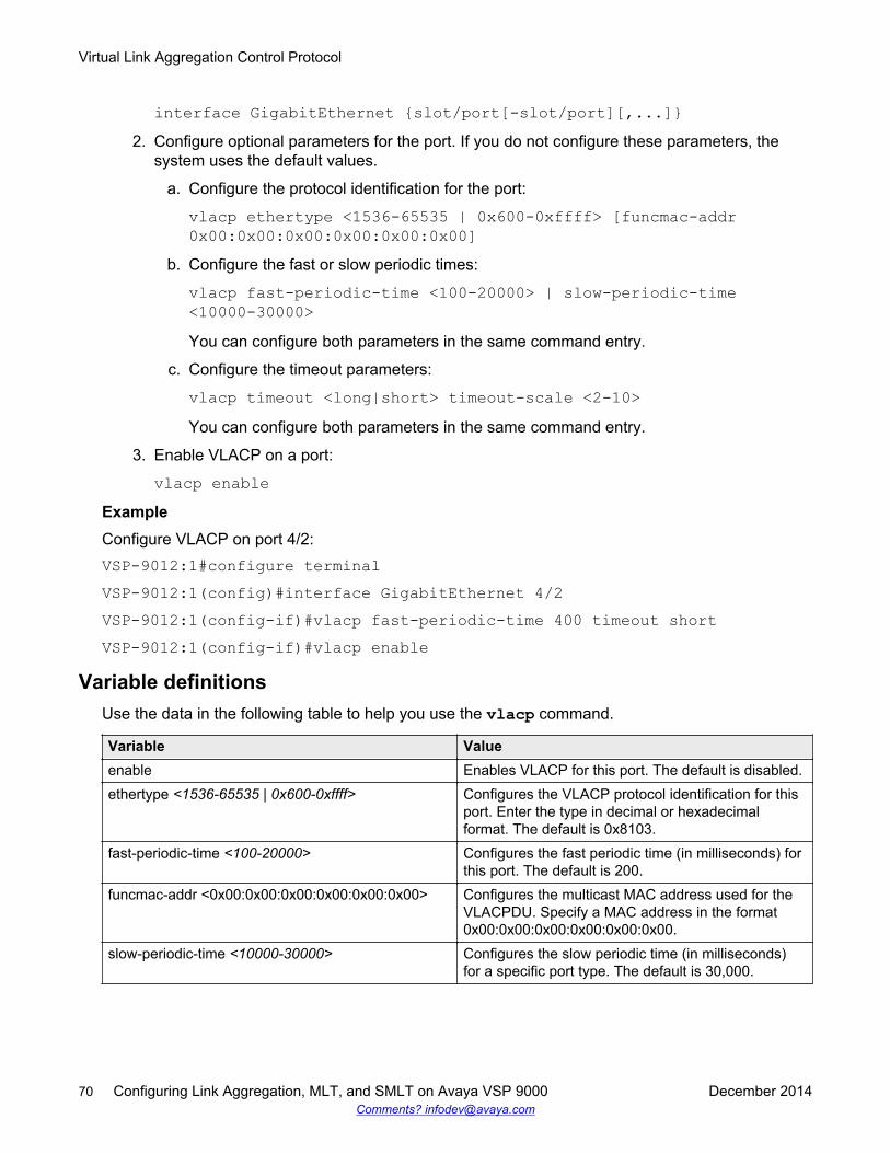
interface GigabitEthernet {slot/port[-slot/port][,...]}2. Configure optional parameters for the port. If you do not configure these parameters, the
system uses the default values.
a. Configure the protocol identification for the port:
vlacp ethertype <1536-65535 | 0x600-0xffff> [funcmac-addr0x00:0x00:0x00:0x00:0x00:0x00]
b. Configure the fast or slow periodic times:
vlacp fast-periodic-time <100-20000> | slow-periodic-time<10000-30000>You can configure both parameters in the same command entry.
c. Configure the timeout parameters:
vlacp timeout <long|short> timeout-scale <2-10>You can configure both parameters in the same command entry.
3. Enable VLACP on a port:
vlacp enableExampleConfigure VLACP on port 4/2:VSP-9012:1#configure terminalVSP-9012:1(config)#interface GigabitEthernet 4/2VSP-9012:1(config-if)#vlacp fast-periodic-time 400 timeout shortVSP-9012:1(config-if)#vlacp enable
Variable definitionsUse the data in the following table to help you use the vlacp command.
Variable Valueenable Enables VLACP for this port. The default is disabled.ethertype <1536-65535 | 0x600-0xffff> Configures the VLACP protocol identification for this
port. Enter the type in decimal or hexadecimalformat. The default is 0x8103.
fast-periodic-time <100-20000> Configures the fast periodic time (in milliseconds) forthis port. The default is 200.
funcmac-addr <0x00:0x00:0x00:0x00:0x00:0x00> Configures the multicast MAC address used for theVLACPDU. Specify a MAC address in the format0x00:0x00:0x00:0x00:0x00:0x00.
slow-periodic-time <10000-30000> Configures the slow periodic time (in milliseconds)for a specific port type. The default is 30,000.
Virtual Link Aggregation Control Protocol
70 Configuring Link Aggregation, MLT, and SMLT on Avaya VSP 9000 December 2014Comments? [email protected]
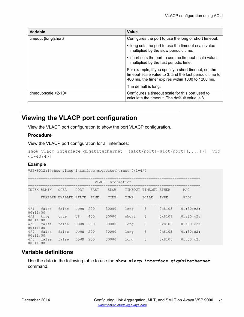
Variable Valuetimeout {long|short} Configures the port to use the long or short timeout:
• long sets the port to use the timeout-scale valuemultiplied by the slow periodic time.
• short sets the port to use the timeout-scale valuemultiplied by the fast periodic time.
For example, if you specify a short timeout, set thetimeout-scale value to 3, and the fast periodic time to400 ms, the timer expires within 1000 to 1200 ms.
The default is long.timeout-scale <2-10> Configures a timeout scale for this port used to
calculate the timeout. The default value is 3.
Viewing the VLACP port configurationView the VLACP port configuration to show the port VLACP configuration.
ProcedureView the VLACP port configuration for all interfaces:
show vlacp interface gigabitethernet [{slot/port[-slot/port][,...]}] [vid<1-4084>]ExampleVSP-9012:1#show vlacp interface gigabitethernet 4/1-4/5
================================================================================ VLACP Information================================================================================INDEX ADMIN OPER PORT FAST SLOW TIMEOUT TIMEOUT ETHER MAC
ENABLED ENABLED STATE TIME TIME TIME SCALE TYPE ADDR
--------------------------------------------------------------------------------4/1 false false DOWN 200 30000 long 3 0x8103 01:80:c2:00:11:004/2 true true UP 400 30000 short 3 0x8103 01:80:c2:00:11:004/3 false false DOWN 200 30000 long 3 0x8103 01:80:c2:00:11:004/4 false false DOWN 200 30000 long 3 0x8103 01:80:c2:00:11:004/5 false false DOWN 200 30000 long 3 0x8103 01:80:c2:00:11:00
Variable definitionsUse the data in the following table to use the show vlacp interface gigabitethernetcommand.
VLACP configuration using ACLI
December 2014 Configuring Link Aggregation, MLT, and SMLT on Avaya VSP 9000 71Comments? [email protected]
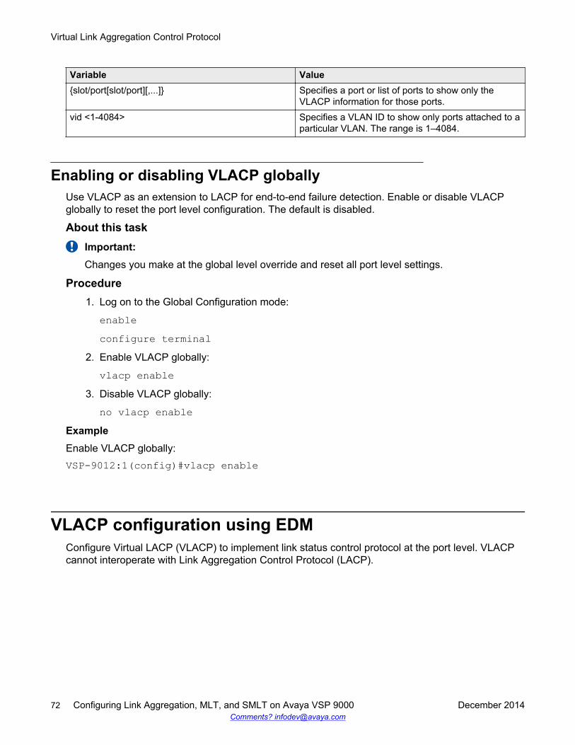
Variable Value{slot/port[slot/port][,...]} Specifies a port or list of ports to show only the
VLACP information for those ports.vid <1-4084> Specifies a VLAN ID to show only ports attached to a
particular VLAN. The range is 1–4084.
Enabling or disabling VLACP globallyUse VLACP as an extension to LACP for end-to-end failure detection. Enable or disable VLACPglobally to reset the port level configuration. The default is disabled.
About this taskImportant:Changes you make at the global level override and reset all port level settings.
Procedure1. Log on to the Global Configuration mode:
enableconfigure terminal
2. Enable VLACP globally:
vlacp enable3. Disable VLACP globally:
no vlacp enableExampleEnable VLACP globally:VSP-9012:1(config)#vlacp enable
VLACP configuration using EDMConfigure Virtual LACP (VLACP) to implement link status control protocol at the port level. VLACPcannot interoperate with Link Aggregation Control Protocol (LACP).
Virtual Link Aggregation Control Protocol
72 Configuring Link Aggregation, MLT, and SMLT on Avaya VSP 9000 December 2014Comments? [email protected]
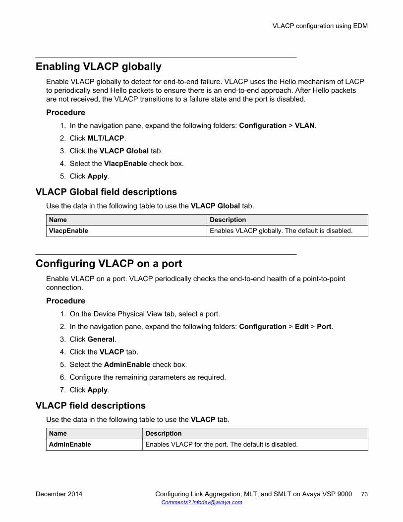
Enabling VLACP globallyEnable VLACP globally to detect for end-to-end failure. VLACP uses the Hello mechanism of LACPto periodically send Hello packets to ensure there is an end-to-end approach. After Hello packetsare not received, the VLACP transitions to a failure state and the port is disabled.
Procedure1. In the navigation pane, expand the following folders: Configuration > VLAN.
2. Click MLT/LACP.
3. Click the VLACP Global tab.
4. Select the VlacpEnable check box.
5. Click Apply.
VLACP Global field descriptionsUse the data in the following table to use the VLACP Global tab.
Name DescriptionVlacpEnable Enables VLACP globally. The default is disabled.
Configuring VLACP on a portEnable VLACP on a port. VLACP periodically checks the end-to-end health of a point-to-pointconnection.
Procedure1. On the Device Physical View tab, select a port.
2. In the navigation pane, expand the following folders: Configuration > Edit > Port.
3. Click General.
4. Click the VLACP tab.
5. Select the AdminEnable check box.
6. Configure the remaining parameters as required.
7. Click Apply.
VLACP field descriptionsUse the data in the following table to use the VLACP tab.
Name DescriptionAdminEnable Enables VLACP for the port. The default is disabled.
VLACP configuration using EDM
December 2014 Configuring Link Aggregation, MLT, and SMLT on Avaya VSP 9000 73Comments? [email protected]
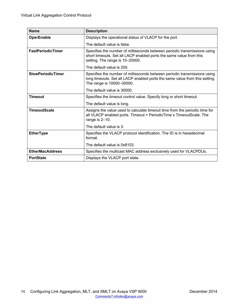
Name DescriptionOperEnable Displays the operational status of VLACP for the port.
The default value is false.FastPeriodicTimer Specifies the number of milliseconds between periodic transmissions using
short timeouts. Set all LACP enabled ports the same value from thissetting. The range is 10–20000.
The default value is 200.SlowPeriodicTimer Specifies the number of milliseconds between periodic transmissions using
long timeouts. Set all LACP enabled ports the same value from this setting.The range is 10000–30000.
The default value is 30000.Timeout Specifies the timeout control value. Specify long or short timeout.
The default value is long.TimeoutScale Assigns the value used to calculate timeout time from the periodic time for
all VLACP enabled ports. Timeout = PeriodicTime x TimeoutScale. Therange is 2–10.
The default value is 3.EtherType Specifies the VLACP protocol identification. The ID is in hexadecimal
format.
The default value is 0x8103.EtherMacAddress Specifies the multicast MAC address exclusively used for VLACPDUs.PortState Displays the VLACP port state.
Virtual Link Aggregation Control Protocol
74 Configuring Link Aggregation, MLT, and SMLT on Avaya VSP 9000 December 2014Comments? [email protected]
Glossary
actor An LACP device at the near end of a link, which performs the action. Thedevice at the far end of the link is called the partner. LACP compares theactor and partner information to determine what action to perform.
Bridge Protocol DataUnit (BPDU)
A data frame used to exchange information among the bridges in local orwide area networks for network topology maintenance.
denial-of-service(DoS)
Attacks that prevent a target server or victim device from performing itsnormal functions through flooding, irregular protocol sizes (for example,ping requests aimed at the victim server), and application buffer overflows.
Distributed MultiLinkTrunking (DMLT)
A point-to-point connection that aggregates similar ports from differentmodules to logically act like a single port, but with the aggregatedbandwidth.
Interior GatewayProtocol (IGP)
Distributes routing information between routers that belong to a singleAutonomous System (AS).
Internet ControlMessage Protocol(ICMP)
A collection of error conditions and control messages exchanged by IPmodules in both hosts and gateways.
interswitch trunking(IST)
A feature that uses one or more parallel point-to-point links to connect twoaggregation switches. The two aggregation switches use this channel toshare information and operate as a single logical switch. Only oneinterswitch trunk can exist on each Split Multilink Trunking (SMLT)aggregation switch.
Layer 2 Layer 2 is the Data Link Layer of the OSI model. Examples of Layer 2protocols are Ethernet and Frame Relay.
Layer 3 Layer 3 is the Network Layer of the OSI model. An example of a Layer 3protocol is Internet Protocol (IP).
Link AggregationControl Protocol(LACP)
A protocol that exists between two endpoints to bundle links into anaggregated link group for bandwidth increase and link redundancy.
December 2014 Configuring Link Aggregation, MLT, and SMLT on Avaya VSP 9000 75Comments? [email protected]
Link AggregationControl ProtocolData Units (LACPDU)
Link aggregation control protocol data unit (LACPDU) is used forexchanging information among LACP-enabled devices.
link aggregationgroup (LAG)
A group that increases the link speed beyond the limits of one single cableor port, and increases the redundancy for higher availability.
load balancing The practice of splitting communication into two (or more) routes or servers.
media A substance that transmits data between ports; usually fiber optic cables orcategory 5 unshielded twisted pair (UTP) copper wires.
Network InterfaceCard (NIC)
A network interface device (NID) in the form of a circuit card installed in anexpansion slot of a computer to provide network access.
packet loss Expressed as a percentage of packets dropped over a specified interval.Keep packet loss to a minimum to deliver effective IP telephony and IPvideo services.
Protocol Data Units(PDUs)
A unit of data that is specified in a protocol of a specific layer and thatconsists of protocol-control information of the specific layer and possiblyuser data of that layer.
Simple LoopPrevention Protocol(SLPP)
Simple Hello Protocol that prevents loops in a Layer 2 network (VLAN).
small form-factorpluggable (SFP)
A hot-swappable input and output enhancement component used withAvaya products to allow gigabit Ethernet ports to link with other gigabitEthernet ports over various media types.
SMLT aggregationswitch
One of two IST peer switches that form a split link aggregation group. Itconnects to multiple wiring closet switches, edge switches, or customerpremise equipment (CPE) devices.
SMLT client A switch located at the edge of the network, such as in a wiring closet orCPE connecting to two SMLT aggregation switches. An SMLT client switchperforms link aggregation but does not require Split MultiLink Trunking(SMLT) intelligence.
spanning tree A simple, fully-connected active topology formed from the arbitrary physicaltopology of connected bridged Local Area Network components by relayingframes through selected bridge ports. The protocol parameters and statesthat are used and exchanged to facilitate the calculation of the activetopology and to control the bridge relay function.
Spanning Tree Group(STG)
A collection of ports in one spanning-tree instance.
Glossary
76 Configuring Link Aggregation, MLT, and SMLT on Avaya VSP 9000 December 2014Comments? [email protected]
Split MultiLinkTrunking (SMLT)
An Avaya extension to IEEE 802.1AX (link aggregation), provides nodaland link failure protection and flexible bandwidth scaling to improve on thelevel of Layer 2 resiliency.
trunk A logical group of ports that behaves like a single large port.
trunk port A port that connects to the service provider network such as the MPLSenvironment.
User DatagramProtocol (UDP)
In TCP/IP, a packet-level protocol built directly on the Internet Protocollayer. TCP/IP host systems use UDP for application-to-applicationprograms.
Virtual LinkAggregation ControlProtocol (VLACP)
Virtual Link Aggregation Control Protocol (VLACP) is a Layer 2handshaking protocol that can detect end-to-end failure between twophysical Ethernet interfaces.
Virtual RouterRedundancyProtocol (VRRP)
A protocol used in static routing configurations, typically at the edge of thenetwork. This protocol operates on multiple routers on an IP subnet andelects a primary gateway router. When the primary router fails, a backuprouter is quickly available to take its place.
wiring closet A central termination area for telephone or network cabling or both.
Split MultiLink Trunking (SMLT)
December 2014 Configuring Link Aggregation, MLT, and SMLT on Avaya VSP 9000 77Comments? [email protected]