Embed Size (px)
Citation preview

AUTOTROL255 LOGIX 740-760
INSTALLER MANUAL
WATER PURIFICATION
Installer Manual 255-LOGIX 740-760 - Table of content
2 / 76 Ref. MKT-IM-001 / C - 08.10.2019
Table of content
1. Generalities . . . . . . . . . . . . . . . . . . . . . . . . . . . . . . . . . . . . . . . . . . 61.1. Scope of the documentation . . . . . . . . . . . . . . . . . . . . . . . . . . . . . . . . 61.2. Release management . . . . . . . . . . . . . . . . . . . . . . . . . . . . . . . . . . . . . 61.3. Manufacturer identifier, product . . . . . . . . . . . . . . . . . . . . . . . . . . . . 61.4. Intended use . . . . . . . . . . . . . . . . . . . . . . . . . . . . . . . . . . . . . . . . . . . . . 61.5. Abbreviations used . . . . . . . . . . . . . . . . . . . . . . . . . . . . . . . . . . . . . . . 71.6. Norms . . . . . . . . . . . . . . . . . . . . . . . . . . . . . . . . . . . . . . . . . . . . . . . . . . 71.6.1. Applicable norms . . . . . . . . . . . . . . . . . . . . . . . . . . . . . . . . . . . . . . . . . . . . 71.6.2. Available certificates . . . . . . . . . . . . . . . . . . . . . . . . . . . . . . . . . . . . . . . . . 71.7. Procedure for technical support . . . . . . . . . . . . . . . . . . . . . . . . . . . . 81.8. Copyright . . . . . . . . . . . . . . . . . . . . . . . . . . . . . . . . . . . . . . . . . . . . . . . 81.9. Limitation of liability . . . . . . . . . . . . . . . . . . . . . . . . . . . . . . . . . . . . . . 81.10. Scan & Service application . . . . . . . . . . . . . . . . . . . . . . . . . . . . . . . . . 9
2. Safety . . . . . . . . . . . . . . . . . . . . . . . . . . . . . . . . . . . . . . . . . . . . . . 102.1. Safety pictograms definition . . . . . . . . . . . . . . . . . . . . . . . . . . . . . . . 102.2. Serial and safety tags location . . . . . . . . . . . . . . . . . . . . . . . . . . . . . 102.3. Hazards . . . . . . . . . . . . . . . . . . . . . . . . . . . . . . . . . . . . . . . . . . . . . . . . 112.3.1. Personnel . . . . . . . . . . . . . . . . . . . . . . . . . . . . . . . . . . . . . . . . . . . . . . . . . 112.3.2. Material . . . . . . . . . . . . . . . . . . . . . . . . . . . . . . . . . . . . . . . . . . . . . . . . . . . 112.4. Hygiene and sanitization . . . . . . . . . . . . . . . . . . . . . . . . . . . . . . . . . . 112.4.1. Sanitary issues . . . . . . . . . . . . . . . . . . . . . . . . . . . . . . . . . . . . . . . . . . . . . 112.4.2. Hygiene measures . . . . . . . . . . . . . . . . . . . . . . . . . . . . . . . . . . . . . . . . . . 12
3. Description . . . . . . . . . . . . . . . . . . . . . . . . . . . . . . . . . . . . . . . . . 133.1. Technical specifications . . . . . . . . . . . . . . . . . . . . . . . . . . . . . . . . . . 133.1.1. Performance flow rate characteristics . . . . . . . . . . . . . . . . . . . . . . . . . . 143.2. Outline drawing . . . . . . . . . . . . . . . . . . . . . . . . . . . . . . . . . . . . . . . . . 153.3. Description and components location . . . . . . . . . . . . . . . . . . . . . . . 163.4. System regeneration cycle (8-cycles operation) . . . . . . . . . . . . . . . 17
4. System sizing . . . . . . . . . . . . . . . . . . . . . . . . . . . . . . . . . . . . . . . 194.1. Recommendations . . . . . . . . . . . . . . . . . . . . . . . . . . . . . . . . . . . . . . . 194.1.1. Injector/DLFC/Refill flow controler-Valve configuration . . . . . . . . . . . 194.2. Cycle time calculation . . . . . . . . . . . . . . . . . . . . . . . . . . . . . . . . . . . . 194.3. Injector flow rates (tables) . . . . . . . . . . . . . . . . . . . . . . . . . . . . . . . . 204.4. Salt amount definition . . . . . . . . . . . . . . . . . . . . . . . . . . . . . . . . . . . . 22
Installer Manual 255-LOGIX 740-760 - Table of content
Ref. MKT-IM-001 / C - 08.10.2019 3 / 76
5. Installation . . . . . . . . . . . . . . . . . . . . . . . . . . . . . . . . . . . . . . . . . .235.1. Safety notices for installation . . . . . . . . . . . . . . . . . . . . . . . . . . . . . 235.2. Installation environment . . . . . . . . . . . . . . . . . . . . . . . . . . . . . . . . . 235.2.1. General. . . . . . . . . . . . . . . . . . . . . . . . . . . . . . . . . . . . . . . . . . . . . . . . . . . 235.2.2. Electrical . . . . . . . . . . . . . . . . . . . . . . . . . . . . . . . . . . . . . . . . . . . . . . . . . 235.2.3. Mechanical. . . . . . . . . . . . . . . . . . . . . . . . . . . . . . . . . . . . . . . . . . . . . . . . 245.2.4. Outdoor Locations . . . . . . . . . . . . . . . . . . . . . . . . . . . . . . . . . . . . . . . . . . 245.3. Integration constraints . . . . . . . . . . . . . . . . . . . . . . . . . . . . . . . . . . 255.4. Block diagram and configuration example . . . . . . . . . . . . . . . . . . 265.5. Valve connection to piping . . . . . . . . . . . . . . . . . . . . . . . . . . . . . . . . 275.5.1. Top-mounted valve installation . . . . . . . . . . . . . . . . . . . . . . . . . . . . . . . 275.6. Connections (electrical) . . . . . . . . . . . . . . . . . . . . . . . . . . . . . . . . . . 295.7. Bypassing . . . . . . . . . . . . . . . . . . . . . . . . . . . . . . . . . . . . . . . . . . . . . 295.8. Drain line connection . . . . . . . . . . . . . . . . . . . . . . . . . . . . . . . . . . . . 305.9. Overflow line connection . . . . . . . . . . . . . . . . . . . . . . . . . . . . . . . . . 315.10. Brine line connection . . . . . . . . . . . . . . . . . . . . . . . . . . . . . . . . . . . . 32
6. Programming . . . . . . . . . . . . . . . . . . . . . . . . . . . . . . . . . . . . . . . .336.1. Display . . . . . . . . . . . . . . . . . . . . . . . . . . . . . . . . . . . . . . . . . . . . . . . . 336.2. Commands . . . . . . . . . . . . . . . . . . . . . . . . . . . . . . . . . . . . . . . . . . . . 356.3. Basic programming . . . . . . . . . . . . . . . . . . . . . . . . . . . . . . . . . . . . . 366.3.1. Basic programming mode chart . . . . . . . . . . . . . . . . . . . . . . . . . . . . . . 366.3.2. Program system size . . . . . . . . . . . . . . . . . . . . . . . . . . . . . . . . . . . . . . . 376.3.3. Time setting and winter time - summer time change . . . . . . . . . . . . . 376.3.4. Day of week . . . . . . . . . . . . . . . . . . . . . . . . . . . . . . . . . . . . . . . . . . . . . . . 386.3.5. Regeneration time. . . . . . . . . . . . . . . . . . . . . . . . . . . . . . . . . . . . . . . . . . 386.3.6. Days to regenerate (740 time-clock controller only) . . . . . . . . . . . . . . 386.3.7. Calendar override (760 on-demand controller only) . . . . . . . . . . . . . . 396.3.8. Amount of brine used per regeneration . . . . . . . . . . . . . . . . . . . . . . . . 396.3.9. Estimated capacity . . . . . . . . . . . . . . . . . . . . . . . . . . . . . . . . . . . . . . . . . 406.3.10. Hardness (760 on-demand controller only) . . . . . . . . . . . . . . . . . . . . . 406.4. Advanced programming . . . . . . . . . . . . . . . . . . . . . . . . . . . . . . . . . . 416.4.1. Master setting reference chart . . . . . . . . . . . . . . . . . . . . . . . . . . . . . . . 426.4.2. Cycle time programming . . . . . . . . . . . . . . . . . . . . . . . . . . . . . . . . . . . . 436.4.3. Diagnostic . . . . . . . . . . . . . . . . . . . . . . . . . . . . . . . . . . . . . . . . . . . . . . . . 446.4.4. Resetting the controller . . . . . . . . . . . . . . . . . . . . . . . . . . . . . . . . . . . . . 44
Installer Manual 255-LOGIX 740-760 - Table of content
4 / 76 Ref. MKT-IM-001 / C - 08.10.2019
7. Commissioning . . . . . . . . . . . . . . . . . . . . . . . . . . . . . . . . . . . . . . 457.1. Water filling, draining and waterproofness inspection . . . . . . . . . 457.1.1. Activating the softener . . . . . . . . . . . . . . . . . . . . . . . . . . . . . . . . . . . . . . . 457.1.2. Additional tips . . . . . . . . . . . . . . . . . . . . . . . . . . . . . . . . . . . . . . . . . . . . . . 477.2. Sanitization . . . . . . . . . . . . . . . . . . . . . . . . . . . . . . . . . . . . . . . . . . . . . 477.2.1. Disinfection of water softeners . . . . . . . . . . . . . . . . . . . . . . . . . . . . . . . . 477.2.2. Sodium or calcium hypochlorite . . . . . . . . . . . . . . . . . . . . . . . . . . . . . . . 487.2.3. Electro chlorination . . . . . . . . . . . . . . . . . . . . . . . . . . . . . . . . . . . . . . . . . 48
8. Operation . . . . . . . . . . . . . . . . . . . . . . . . . . . . . . . . . . . . . . . . . . . 498.1. Recommendations . . . . . . . . . . . . . . . . . . . . . . . . . . . . . . . . . . . . . . . 498.2. Manual regeneration . . . . . . . . . . . . . . . . . . . . . . . . . . . . . . . . . . . . . 498.3. To advance regeneration cycles . . . . . . . . . . . . . . . . . . . . . . . . . . . . 508.4. To cancel a regeneration . . . . . . . . . . . . . . . . . . . . . . . . . . . . . . . . . 50
9. Maintenance . . . . . . . . . . . . . . . . . . . . . . . . . . . . . . . . . . . . . . . . 519.1. General system inspection . . . . . . . . . . . . . . . . . . . . . . . . . . . . . . . . 519.1.1. Water quality . . . . . . . . . . . . . . . . . . . . . . . . . . . . . . . . . . . . . . . . . . . . . . . 519.1.2. Mechanical Checks . . . . . . . . . . . . . . . . . . . . . . . . . . . . . . . . . . . . . . . . . . 519.1.3. Regeneration test . . . . . . . . . . . . . . . . . . . . . . . . . . . . . . . . . . . . . . . . . . . 529.2. Recommended maintenance plan . . . . . . . . . . . . . . . . . . . . . . . . . . 529.3. Recommendations . . . . . . . . . . . . . . . . . . . . . . . . . . . . . . . . . . . . . . . 549.3.1. Use original spare parts. . . . . . . . . . . . . . . . . . . . . . . . . . . . . . . . . . . . . . 549.3.2. Use original approved lubricants . . . . . . . . . . . . . . . . . . . . . . . . . . . . . . 549.3.3. Maintenance instructions. . . . . . . . . . . . . . . . . . . . . . . . . . . . . . . . . . . . . 549.4. Cleaning and maintenance . . . . . . . . . . . . . . . . . . . . . . . . . . . . . . . . 549.4.1. First steps . . . . . . . . . . . . . . . . . . . . . . . . . . . . . . . . . . . . . . . . . . . . . . . . . 549.4.2. Injector cleaning . . . . . . . . . . . . . . . . . . . . . . . . . . . . . . . . . . . . . . . . . . . . 559.4.3. Refill controller cleaning . . . . . . . . . . . . . . . . . . . . . . . . . . . . . . . . . . . . . 559.4.4. Injector screen cap cleaning . . . . . . . . . . . . . . . . . . . . . . . . . . . . . . . . . . 569.4.5. Backwash controller cleaning . . . . . . . . . . . . . . . . . . . . . . . . . . . . . . . . . 569.4.6. Air check valve cleaning . . . . . . . . . . . . . . . . . . . . . . . . . . . . . . . . . . . . . . 579.4.7. Valve from tank disassembly . . . . . . . . . . . . . . . . . . . . . . . . . . . . . . . . . 589.4.8. Motor and camshaft replacement . . . . . . . . . . . . . . . . . . . . . . . . . . . . . . 599.4.9. Optical sensor and controller replacement . . . . . . . . . . . . . . . . . . . . . . 609.4.10. Top plate and disc valve replacement. . . . . . . . . . . . . . . . . . . . . . . . . . . 619.4.11. Valve on tank assembly . . . . . . . . . . . . . . . . . . . . . . . . . . . . . . . . . . . . . . 62
10. Troubleshooting . . . . . . . . . . . . . . . . . . . . . . . . . . . . . . . . . . . . . 63
Installer Manual 255-LOGIX 740-760 - Table of content
Ref. MKT-IM-001 / C - 08.10.2019 5 / 76
11. Spare parts . . . . . . . . . . . . . . . . . . . . . . . . . . . . . . . . . . . . . . . . . .6711.1. Valve parts list . . . . . . . . . . . . . . . . . . . . . . . . . . . . . . . . . . . . . . . . . 6711.2. Options and special kits . . . . . . . . . . . . . . . . . . . . . . . . . . . . . . . . . . 70
12. Disposal . . . . . . . . . . . . . . . . . . . . . . . . . . . . . . . . . . . . . . . . . . . . .75
Installer Manual 255-LOGIX 740-760 - Generalities
6 / 76 Ref. MKT-IM-001 / C - 08.10.2019
1. Generalities
1.1. Scope of the documentationThe documentation provides the necessary information for appropriate use of the product. It informs the user to ensure efficient execution of the installation, operation or maintenance procedures.The content of this document is based on the information available at the time of publication. The original version of the document was written in English.For safety and environmental protection reasons, the safety instructions given in this documentation must be strictly followed.This manual is a reference and will not include every system installation situation. The person installing this equipment should have:• training in the 700 Logix series controllers and water softener installation;• knowledge of water conditioning and how to determine proper controller settings;• basic plumbing skills.This document is available in other languages on https://www.pentairaquaeurope.com/product-finder/product-type/control-valves.
1.2. Release management
1.3. Manufacturer identifier, productManufacturer: Pentair International LLC
Avenue de Sevelin 181004 LausanneSwitzerland
Product: 255-LOGIX 740-760
1.4. Intended useThe device is intended to be used for domestic applications only and it is purpose-built for water treatment.
Revision Date Authors DescriptionA 18.11.2016 STF/FLA First edition.
B 23.05.2018 BRY/FLA Address change, Bleam information and valve on tank assembly.
C 08.10.2019 STF General corrections.
Installer Manual 255-LOGIX 740-760 - Generalities
Ref. MKT-IM-001 / C - 08.10.2019 7 / 76
1.5. Abbreviations usedBLFC ................................................................................. Brine Line Flow ControllerDF...................................................................................... Down FlowDLFC ................................................................................. Drain Line Flow ControllerInj ...................................................................................... InjectorPN ..................................................................................... Part NumberQC...................................................................................... Quick ConnectRegen ................................................................................ RegenerationSBV.................................................................................... Safety Brine ValveTC ...................................................................................... Time ClockUF...................................................................................... Up Flow
1.6. Norms1.6.1. Applicable normsComply with the following guidelines:• 2006/42/EC: Machinery Directive;• 2014/35/UE: Low Voltage Directive;• 2014/30/UE: Electromagnetic compatibility;• 2011/65/EC: Restriction of use of certain hazardous substances in electrical and electronic
equipment (RoHS).• UNI EN ISO9001.
Meets the following technical standards:• IEC/EN 60335-1• IEC 61010-1• EN 55014-1• EN 55014-2• EN 61000-3-2: 2006 + A1: 2009 + A2: 2009• EN 61000-3-3: 2008• EN 61000-6-2: 2005• EN 61000-6-3: 2007 + A1: 2011• EN 61326-1
1.6.2. Available certificates• CE• DM174• ACS
Please find beside the certifications for some of our product families. Please note that this list is not an exhaustive list of all our certifications. In case of need for more information please contact us.
Installer Manual 255-LOGIX 740-760 - Generalities
8 / 76 Ref. MKT-IM-001 / C - 08.10.2019
1.7. Procedure for technical supportProcedure to follow for any technical support request:A Collect the required information for a technical assistance request.
→ Product identification (see 2.2. Serial and safety tags location, page 10 and 9.3. Recommendations, page 54);
→ Problem description of the device.B Please refer to the "Troubleshooting" chapter, page 63. If the problem persists contact your
supplier.
1.8. Copyright© 2019 Pentair International Sàrl All rights reserved.
1.9. Limitation of liability Pentair Quality System EMEA products benefit, under specific conditions, from a manufacturer warranty that may be invoked by Pentair’s direct customers. Users should contact the vendor of this product for applicable conditions and in case of a potential warranty claim. Any warranty provided by Pentair regarding the product will become invalid in case of:• improper installation, improper programming, improper use, improper operation and/or
maintenance leading to any kind of product damages;• improper or unauthorized intervention on the controller or components;• incorrect, improper or wrong connection/assembly of systems or products with this product and
vice versa;• use of a non-compatible lubricant, grease or chemicals of any type and not listed by the
manufacturer as compatible for the product;• failure due to wrong configuration and/or sizing.
Pentair accepts no liability for equipment installed by the user upstream or downstream of Pentair products, as well as for process/production processes which are installed and connected around or even related to the installation. Disturbances, failures, direct or indirect damages that are caused by such equipment or processes are also excluded from the warranty. Pentair shall not accept any liability for any loss or damage of profits, revenues, use, production, or contracts, or for any indirect, special or consequential loss or damage whatsoever. Please refer to the Pentair List Price to know more about terms and conditions applicable to this product.
Installer Manual 255-LOGIX 740-760 - Generalities
Ref. MKT-IM-001 / C - 08.10.2019 9 / 76
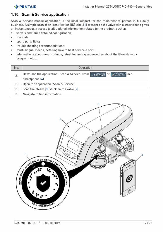
1.10. Scan & Service applicationScan & Service mobile application is the ideal support for the maintenance person in his daily business. A simple scan of an identification (ID) label (1) present on the valve with a smartphone gives an instantaneously access to all updated information related to the product, such as:• valve’s and tanks detailed configuration;• manuals;• spare parts lists;• troubleshooting recommendations;• multi-lingual videos, detailing how to best service a part;• informations about new products, latest technologies, novelties about the Blue Network
program, etc....
No. Operation
A Download the application "Scan & Service" from or in a smartphone (4).
B Open the application "Scan & Service".C Scan the bleam (3) stuck on the valve (2).D Navigate to find information.
Installer Manual 255-LOGIX 740-760 - Safety
10 / 76 Ref. MKT-IM-001 / C - 08.10.2019
2. Safety
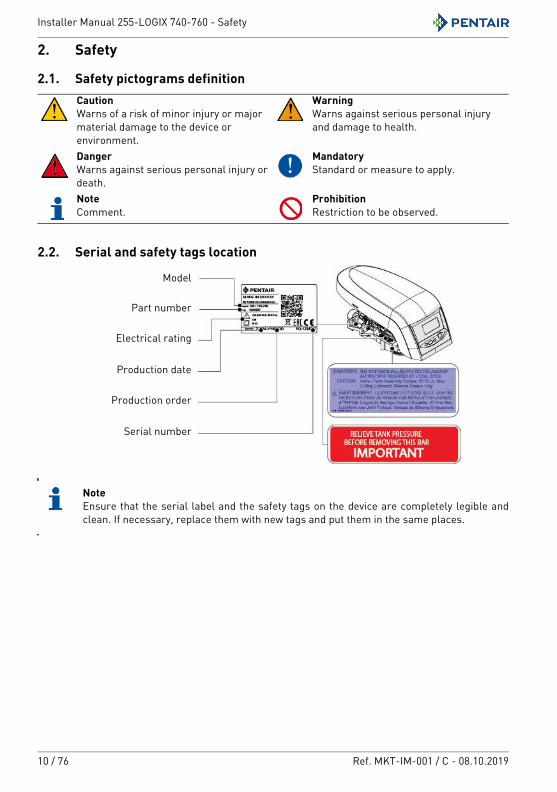
2.1. Safety pictograms definition
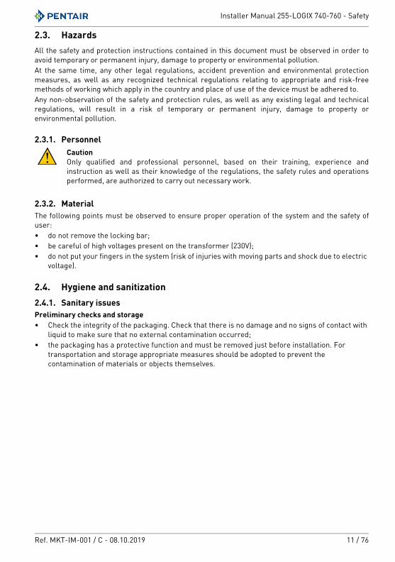
2.2. Serial and safety tags location
NoteEnsure that the serial label and the safety tags on the device are completely legible and clean. If necessary, replace them with new tags and put them in the same places.
CautionWarns of a risk of minor injury or major material damage to the device or environment.
WarningWarns against serious personal injury and damage to health.
DangerWarns against serious personal injury or death.
MandatoryStandard or measure to apply.
NoteComment.
ProhibitionRestriction to be observed.
Model
Electrical rating
Part number
Production date
Production order
Serial number
Installer Manual 255-LOGIX 740-760 - Safety
Ref. MKT-IM-001 / C - 08.10.2019 11 / 76
2.3. HazardsAll the safety and protection instructions contained in this document must be observed in order to avoid temporary or permanent injury, damage to property or environmental pollution.At the same time, any other legal regulations, accident prevention and environmental protection measures, as well as any recognized technical regulations relating to appropriate and risk-free methods of working which apply in the country and place of use of the device must be adhered to.Any non-observation of the safety and protection rules, as well as any existing legal and technical regulations, will result in a risk of temporary or permanent injury, damage to property or environmental pollution.
2.3.1. PersonnelCautionOnly qualified and professional personnel, based on their training, experience and instruction as well as their knowledge of the regulations, the safety rules and operations performed, are authorized to carry out necessary work.
2.3.2. MaterialThe following points must be observed to ensure proper operation of the system and the safety of user:• do not remove the locking bar;• be careful of high voltages present on the transformer (230V);• do not put your fingers in the system (risk of injuries with moving parts and shock due to electric
voltage).
2.4. Hygiene and sanitization2.4.1. Sanitary issuesPreliminary checks and storage• Check the integrity of the packaging. Check that there is no damage and no signs of contact with
liquid to make sure that no external contamination occurred;• the packaging has a protective function and must be removed just before installation. For
transportation and storage appropriate measures should be adopted to prevent the contamination of materials or objects themselves.
Installer Manual 255-LOGIX 740-760 - Safety
12 / 76 Ref. MKT-IM-001 / C - 08.10.2019
Assembly• Assemble only with components which are in accordance with DM 174 and ACS;• after installation and before use, perform one or more manual regenerations in order to clean
the media bed. During such operations, do not use the water for human consumption. Perform a disinfection of the system in the case of installations for treatment of drinking water for human use.
NoteThis operation must be repeated in the case of ordinary and extraordinary maintenance. It should also be repeated whenever the system remains idle for a significant time.NoteValid only for Italy: In case of equipment used in accordance with the DM25, apply all the signs and obligations arising from the DM25.
2.4.2. Hygiene measuresDisinfection• The materials used for the construction of our products meet the standards for use with potable
water; the manufacturing processes are also geared to preserving these criteria. However, the process of production, distribution, assembly and installation, may create conditions of bacterial proliferation, which may lead to odor problems and water contamination;
• it is therefore strongly recommended to sanitize the products. See 7.2. Sanitization, page 47;• maximum cleanliness is recommended during the assembly and installation;• for disinfection, use Sodium or Calcium Hypochlorite and perform a manual regeneration.
Installer Manual 255-LOGIX 740-760 - Description
Ref. MKT-IM-001 / C - 08.10.2019 13 / 76
3. Description
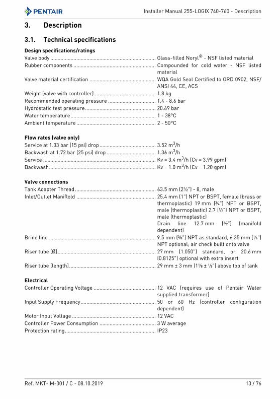
3.1. Technical specifications Design specifications/ratingsValve body ......................................................................... Glass-filled Noryl® - NSF listed materialRubber components ......................................................... Compounded for cold water - NSF listed
materialValve material certification .............................................. WQA Gold Seal Certified to ORD 0902, NSF/
ANSI 44, CE, ACSWeight (valve with controller)........................................... 1.8 kg Recommended operating pressure ................................. 1.4 - 8.6 bar Hydrostatic test pressure................................................. 20.69 bar Water temperature........................................................... 1 - 38°CAmbient temperature ....................................................... 2 - 50°C
Flow rates (valve only)Service at 1.03 bar (15 psi) drop....................................... 3.52 m3/h Backwash at 1.72 bar (25 psi) drop .................................. 1.36 m3/h Service .............................................................................. Kv = 3.4 m3/h (Cv = 3.99 gpm)Backwash.......................................................................... Kv = 1.0 m3/h (Cv = 1.20 gpm)
Valve connectionsTank Adapter Thread ........................................................ 63.5 mm (2½") - 8, maleInlet/Outlet Maniflold ....................................................... 25.4 mm (1") NPT or BSPT, female (brass or
thermoplastic) 19 mm (¾") NPT or BSPT, male (thermoplastic) 2.7 (½") NPT or BSPT, male (thermoplastic)Drain line 12.7 mm (½") (manifold dependent)
Brine line .......................................................................... 9.5 mm (⅜") NPT as standard, 6.35 mm (¼") NPT optional; air check built onto valve
Riser tube [Ø].................................................................... 27 mm (1.050") standard, or 20.6 mm (0.8125") optional with extra insert
Riser tube [length]............................................................ 29 mm ± 3 mm (1⅛ ± ⅛") above top of tank
ElectricalController Operating Voltage ........................................... 12 VAC (requires use of Pentair Water
supplied transformer)Input Supply Frequency.................................................... 50 or 60 Hz (controller configuration
dependent)Motor Input Voltage .......................................................... 12 VACController Power Consumption ....................................... 3 W averageProtection rating............................................................... IP23
Installer Manual 255-LOGIX 740-760 - Description
14 / 76 Ref. MKT-IM-001 / C - 08.10.2019
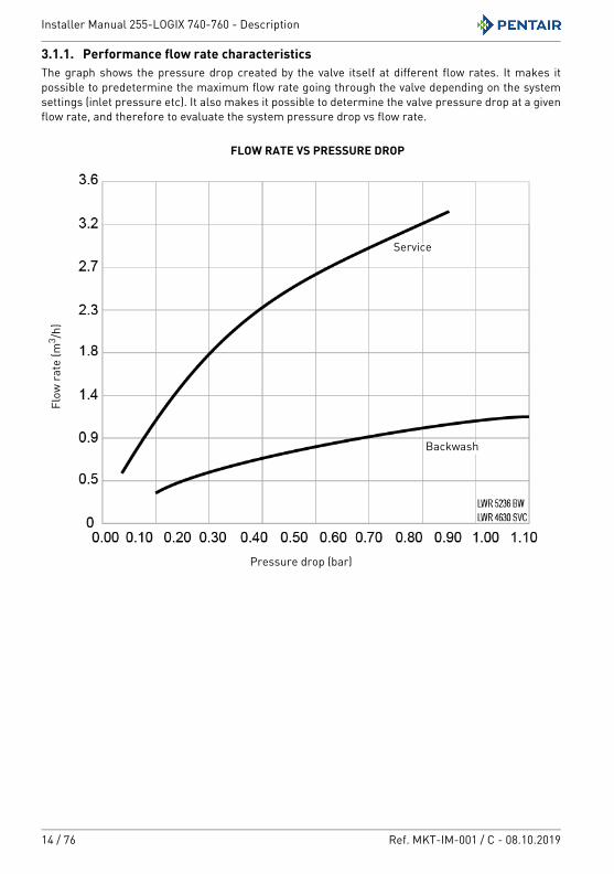
3.1.1. Performance flow rate characteristicsThe graph shows the pressure drop created by the valve itself at different flow rates. It makes it possible to predetermine the maximum flow rate going through the valve depending on the system settings (inlet pressure etc). It also makes it possible to determine the valve pressure drop at a given flow rate, and therefore to evaluate the system pressure drop vs flow rate.
Flow
rate
(m3 /h
)
Pressure drop (bar)
Backwash
Service
FLOW RATE VS PRESSURE DROP
Installer Manual 255-LOGIX 740-760 - Description
Ref. MKT-IM-001 / C - 08.10.2019 15 / 76
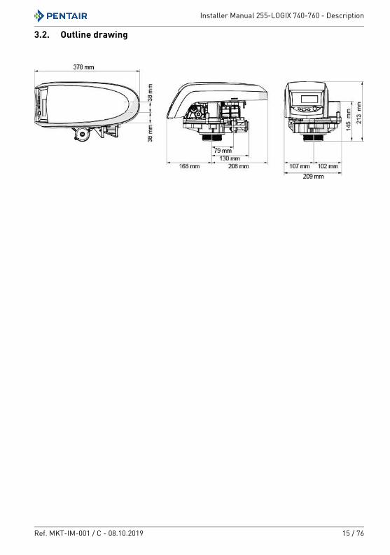
3.2. Outline drawing
Installer Manual 255-LOGIX 740-760 - Description
16 / 76 Ref. MKT-IM-001 / C - 08.10.2019
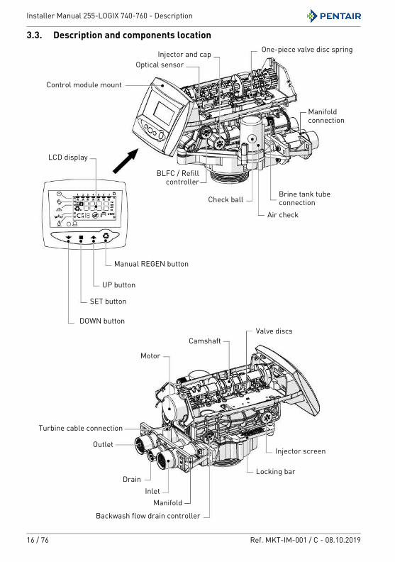
3.3. Description and components location
LCD display
DOWN button
SET button
UP button
Manual REGEN button
Control module mount
BLFC / Refill controller
Injector and cap
Check ball
Air check
Brine tank tube connection
Manifold connection
One-piece valve disc spring
Valve discs
Optical sensor
Camshaft
Motor
Turbine cable connection
DrainInlet
Backwash flow drain controller
Locking bar
Injector screenOutlet
Manifold
Installer Manual 255-LOGIX 740-760 - Description
Ref. MKT-IM-001 / C - 08.10.2019 17 / 76
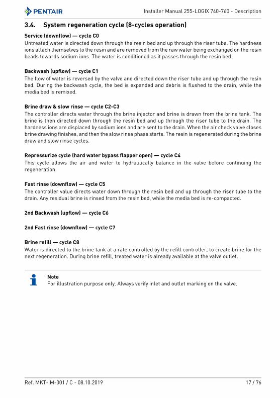
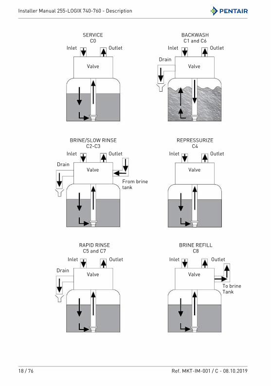
3.4. System regeneration cycle (8-cycles operation)Service (downflow) — cycle C0Untreated water is directed down through the resin bed and up through the riser tube. The hardness ions attach themselves to the resin and are removed from the raw water being exchanged on the resin beads towards sodium ions. The water is conditioned as it passes through the resin bed.
Backwash (upflow) — cycle C1The flow of water is reversed by the valve and directed down the riser tube and up through the resin bed. During the backwash cycle, the bed is expanded and debris is flushed to the drain, while the media bed is remixed.
Brine draw & slow rinse — cycle C2-C3The controller directs water through the brine injector and brine is drawn from the brine tank. The brine is then directed down through the resin bed and up through the riser tube to the drain. The hardness ions are displaced by sodium ions and are sent to the drain. When the air check valve closes brine drawing finishes, and then the slow rinse phase starts. The resin is regenerated during the brine draw and slow rinse cycles.
Repressurize cycle (hard water bypass flapper open) — cycle C4This cycle allows the air and water to hydraulically balance in the valve before continuing the regeneration.
Fast rinse (downflow) — cycle C5The controller value directs water down through the resin bed and up through the riser tube to the drain. Any residual brine is rinsed from the resin bed, while the media bed is re-compacted.
2nd Backwash (upflow) — cycle C6
2nd Fast rinse (downflow) — cycle C7
Brine refill — cycle C8Water is directed to the brine tank at a rate controlled by the refill controller, to create brine for the next regeneration. During brine refill, treated water is already available at the valve outlet.
NoteFor illustration purpose only. Always verify inlet and outlet marking on the valve.
Installer Manual 255-LOGIX 740-760 - Description
18 / 76 Ref. MKT-IM-001 / C - 08.10.2019
From brine tank
To brine Tank
BRINE/SLOW RINSEC2-C3
BACKWASHC1 and C6
SERVICEC0
REPRESSURIZEC4
RAPID RINSEC5 and C7
BRINE REFILLC8
Valve
Valve
Valve
Valve Valve
Valve
Inlet Outlet Inlet Outlet
Inlet Outlet Inlet Outlet
Inlet Outlet Inlet Outlet
Drain
Drain
Drain
Installer Manual 255-LOGIX 740-760 - System sizing
Ref. MKT-IM-001 / C - 08.10.2019 19 / 76
4. System sizing
4.1. Recommendations
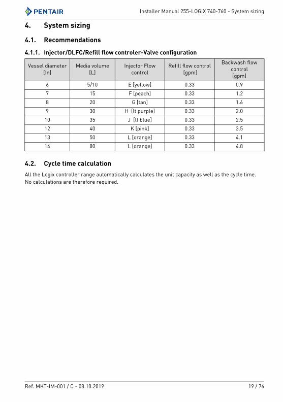
4.1.1. Injector/DLFC/Refill flow controler-Valve configuration
4.2. Cycle time calculationAll the Logix controller range automatically calculates the unit capacity as well as the cycle time.No calculations are therefore required.
Vessel diameter[In]
Media volume[L]
Injector Flow control
Refill flow control [gpm]
Backwash flow control[gpm]
6 5/10 E [yellow] 0.33 0.97 15 F [peach] 0.33 1.28 20 G [tan] 0.33 1.69 30 H [lt purple] 0.33 2.0
10 35 J [lt blue] 0.33 2.512 40 K [pink] 0.33 3.513 50 L [orange] 0.33 4.114 80 L [orange] 0.33 4.8
Installer Manual 255-LOGIX 740-760 - System sizing
20 / 76 Ref. MKT-IM-001 / C - 08.10.2019
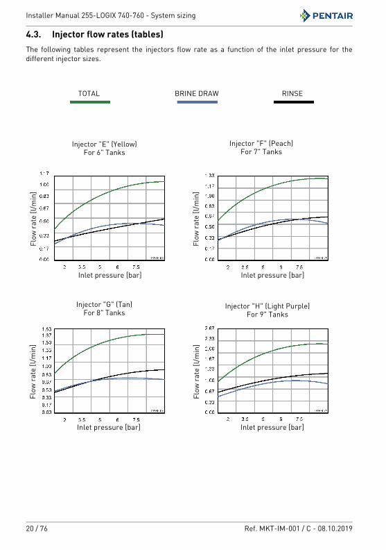
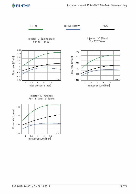
4.3. Injector flow rates (tables)The following tables represent the injectors flow rate as a function of the inlet pressure for the different injector sizes.
TOTAL
Inlet pressure [bar]
Injector "F" (Peach)For 7" Tanks
Injector "G" (Tan)For 8" Tanks
Injector "H" (Light Purple)For 9" Tanks
Flow
rate
[l/m
in]
RINSEBRINE DRAW
Injector "E" (Yellow)For 6" Tanks
Inlet pressure [bar]
Flow
rate
[l/m
in]
Inlet pressure [bar]
Flow
rate
[l/m
in]
Inlet pressure [bar]
Flow
rate
[l/m
in]
Installer Manual 255-LOGIX 740-760 - System sizing
Ref. MKT-IM-001 / C - 08.10.2019 21 / 76
Injector "K" (Pink)For 12" Tanks
Injector "L" (Orange)For 13 " and 14" Tanks
Injector "J" (Light Blue)For 10" Tanks
TOTAL RINSEBRINE DRAW
Inlet pressure [bar]
Flow
rate
[l/m
in]
Inlet pressure [bar]
Flow
rate
[l/m
in]
Inlet pressure [bar]
Flow
rate
[l/m
in]
Installer Manual 255-LOGIX 740-760 - System sizing
22 / 76 Ref. MKT-IM-001 / C - 08.10.2019
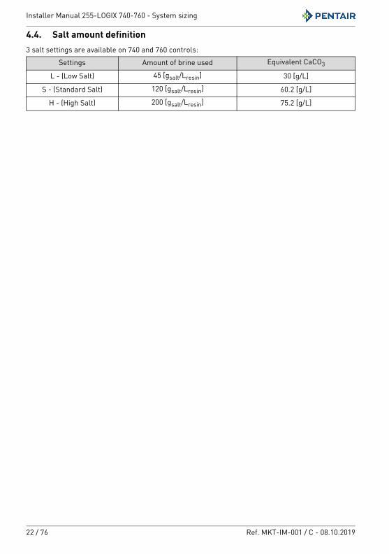
4.4. Salt amount definition3 salt settings are available on 740 and 760 controls:
Settings Amount of brine used Equivalent CaCO3
L - (Low Salt) 45 [gsalt/Lresin] 30 [g/L]
S - (Standard Salt) 120 [gsalt/Lresin] 60.2 [g/L]
H - (High Salt) 200 [gsalt/Lresin] 75.2 [g/L]
Installer Manual 255-LOGIX 740-760 - Installation
Ref. MKT-IM-001 / C - 08.10.2019 23 / 76
5. Installation
5.1. Safety notices for installation• Observe all warnings that appear in this manual;• only qualified and professional personnel are authorized to carry out installation work.
5.2. Installation environment5.2.1. General• Use only brine salts designed for water softening. Do not use ice melt salt, block, or rock salts;• keep the media tank in the upright position. Do not turn on its side, upside down, or drop. Turning
the tank upside down may cause media to enter the valve or might plug the upper screen;• follow State and local codes for water testing. Do not use water that is micro-biologically unsafe
or of unknown quality;• when filling media tank, first place the control valve in backwash position, then do not open
water valve completely. Fill tank slowly to prevent media from exiting the tank;• when installing the water connection (bypass or manifold) connect to the plumbing system first.
Allow heated parts to cool and cemented parts to set before installing any plastic parts. Do not get primer or solvent on O-rings, nuts, or the valve.
5.2.2. ElectricalThere are no user-serviceable parts in the AC transformer, motor, or controller. In the event of a failure, these should be replaced.• All electrical connections must be completed according to local codes;• use only the power AC transformer that is supplied;
MandatoryThe use of any other power transformer than the one supplied void the warranty of all electronic parts of the valve.
• the power outlet must be grounded;• to disconnect power, unplug the AC transformer from its power source.
Installer Manual 255-LOGIX 740-760 - Installation
24 / 76 Ref. MKT-IM-001 / C - 08.10.2019
5.2.3. Mechanical• Do not use petroleum-based lubricants such as vaseline, oils, or hydrocarbon-based lubricants.
Use only 100% silicone lubricants;• all plastic connections should be hand tightened. PTFE (plumber’s tape) may be used on
connections that do not use an O-ring seal. Do not use pliers or pipe wrenches;• all plumbing must be completed according to local codes;• soldering near the drain line should be done before connecting the drain line to the valve.
Excessive heat will cause interior damage to the valve;• If the backwash flow rate exceeds 22.7 lpm or if the unit is located 6.1-12.2 m from the drain, use
19 mm (3/4") tubing. Use appropriate fittings to connect the 19 mm (3/4") tubing to the 19 mm(3/4") NPT drain connection on the valve;
• do not use lead-based solder for sweat solder connections;• the drain line must be a minimum of 12.7 mm (½") in diameter. Use 19 mm (¾") pipe if the
backwash flow rate is greater than 26.5 lpm or the pipe length is greater than 6 m;• do not support the weight of the system on the control valve fittings, plumbing, or the bypass;• it is not recommended to use sealants on the threads. Use PTFE (plumber’s tape) on the threads
of the 25.4 mm (1") NPT elbow, the drain line connections, and other NPT/BSP threads.
5.2.4. Outdoor LocationsWhen the water conditioning system is installed outdoors, several points must be considered.• Moisture — The valve and 700 controller are rated for NEMA 3 locations. Falling water should
not affect performance. The system is not designed to withstand extreme humidity or water spray from below. Examples are: constant heavy mist, near corrosive environment, upwards spray from sprinkler;
• direct sunlight — The materials used will fade or discolour over time in direct sunlight. The integrity of the materials will not degrade to cause system failures. If it is necessary to locate the softener in direct sunlight, a protective outdoor cover (PN 1267811) over the valve and controller is necessary;
• temperature — Extreme hot or cold temperatures may cause damage to the valve or controller. Freezing temperatures will freeze the water in the valve. This will cause physical damage to the internal parts as well as the plumbing. High temperatures will affect the controller. The display may become unreadable but the controller should continue to function. When the temperature drops back into normal operating limits the display will return to normal. A protective cover (PN 1267811) should assist with high temperature applications;
• insects — The controller and valve have been designed to keep all but the smallest insects out of the critical areas. Any holes in the top plate can be covered with a metal foil ductwork tape. The top cover should be installed securely in place;
• wind — The Logix cover is designed to withstand a 48 km/h wind when properly installed on the valve.
Installer Manual 255-LOGIX 740-760 - Installation
Ref. MKT-IM-001 / C - 08.10.2019 25 / 76
5.3. Integration constraintsLocation of a water treatment system is important. The following conditions are required:• level platform or floor;• room to access equipment for maintenance and adding brine (salt) to tank;• constant electrical supply to operate the controller;• total minimum pipe run to water heater of 3 m to prevent backup of hot water into system;• always install check valve to protect the softener from hot water return;• local drain for discharge as close as possible;• water line connections with shut off or bypass valves;• must meet any local and state codes for site of installation;• valve is designed for minor plumbing misalignments. Do not support weight of system on the
plumbing;• be sure all soldered pipes are fully cooled before attaching plastic valve to the plumbing.
Installer Manual 255-LOGIX 740-760 - Installation
26 / 76 Ref. MKT-IM-001 / C - 08.10.2019
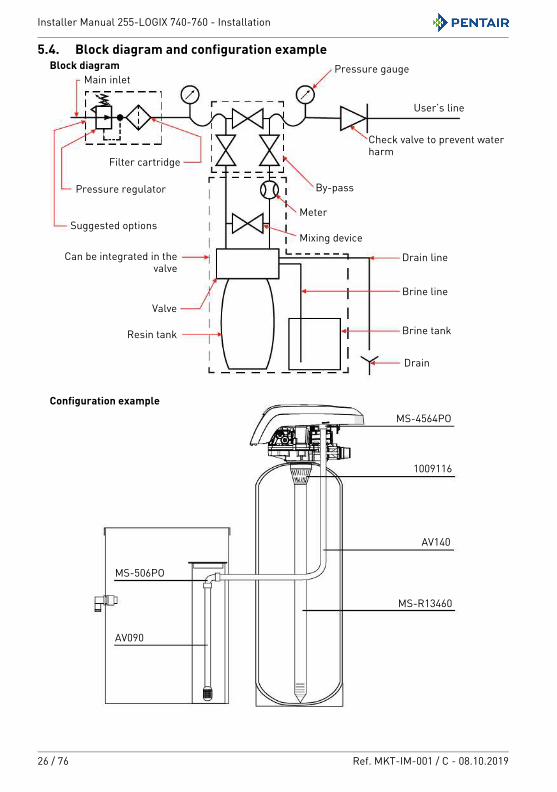
5.4. Block diagram and configuration example
Configuration example
Block diagramMain inlet
By-pass
User’s line
Valve
Meter
Resin tank
Check valve to prevent water harm
Pressure gauge
Can be integrated in the valve
Drain
Brine tank
Brine line
Drain line
Suggested options
Filter cartridge
Pressure regulator
Mixing device
MS-506PO
AV090
MS-4564PO
1009116
AV140
MS-R13460
Installer Manual 255-LOGIX 740-760 - Installation
Ref. MKT-IM-001 / C - 08.10.2019 27 / 76
5.5. Valve connection to pipingThe connections should be hand tightened using PTFE (plumber’s tape) on the threads if using the threaded connection type.In case of heat welding (metal type connection), the connections should not be made to the valve when soldering.
NoteSee chapter 3.3. Description and components location, page 16 to identify the connections.
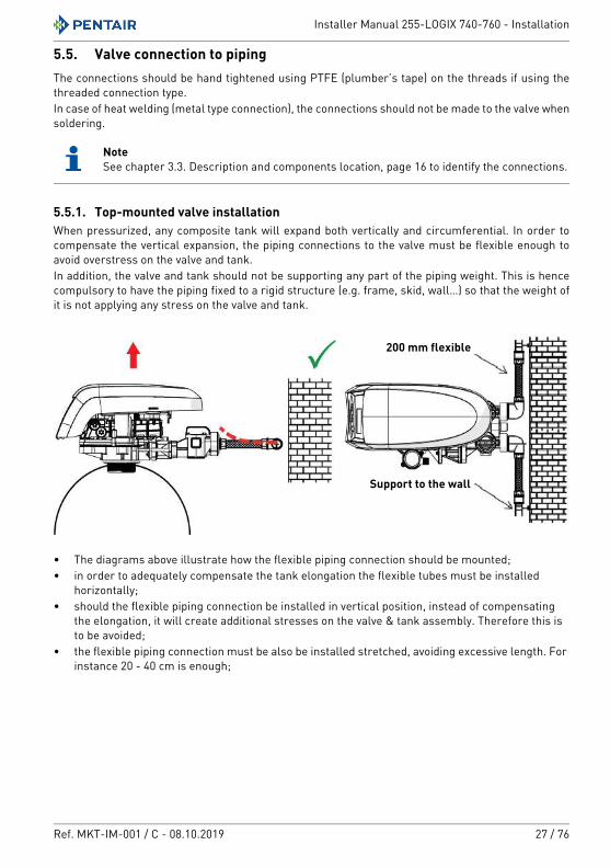
5.5.1. Top-mounted valve installationWhen pressurized, any composite tank will expand both vertically and circumferential. In order to compensate the vertical expansion, the piping connections to the valve must be flexible enough to avoid overstress on the valve and tank.In addition, the valve and tank should not be supporting any part of the piping weight. This is hence compulsory to have the piping fixed to a rigid structure (e.g. frame, skid, wall…) so that the weight of it is not applying any stress on the valve and tank.
• The diagrams above illustrate how the flexible piping connection should be mounted;• in order to adequately compensate the tank elongation the flexible tubes must be installed
horizontally;• should the flexible piping connection be installed in vertical position, instead of compensating
the elongation, it will create additional stresses on the valve & tank assembly. Therefore this is to be avoided;
• the flexible piping connection must be also be installed stretched, avoiding excessive length. For instance 20 - 40 cm is enough;
200 mm flexible
Support to the wall
Installer Manual 255-LOGIX 740-760 - Installation
28 / 76 Ref. MKT-IM-001 / C - 08.10.2019
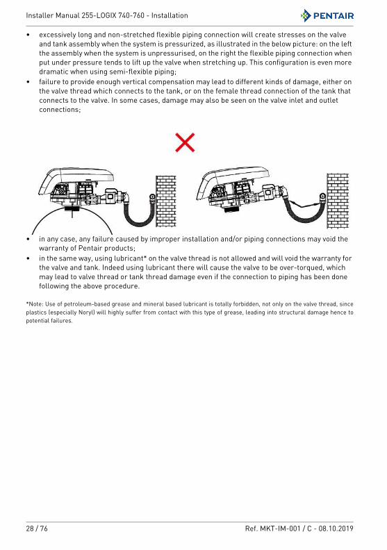
• excessively long and non-stretched flexible piping connection will create stresses on the valve and tank assembly when the system is pressurized, as illustrated in the below picture: on the left the assembly when the system is unpressurised, on the right the flexible piping connection when put under pressure tends to lift up the valve when stretching up. This configuration is even more dramatic when using semi-flexible piping;
• failure to provide enough vertical compensation may lead to different kinds of damage, either on the valve thread which connects to the tank, or on the female thread connection of the tank that connects to the valve. In some cases, damage may also be seen on the valve inlet and outlet connections;
• in any case, any failure caused by improper installation and/or piping connections may void the warranty of Pentair products;
• in the same way, using lubricant* on the valve thread is not allowed and will void the warranty for the valve and tank. Indeed using lubricant there will cause the valve to be over-torqued, which may lead to valve thread or tank thread damage even if the connection to piping has been done following the above procedure.
*Note: Use of petroleum-based grease and mineral based lubricant is totally forbidden, not only on the valve thread, since plastics (especially Noryl) will highly suffer from contact with this type of grease, leading into structural damage hence to potential failures.
Installer Manual 255-LOGIX 740-760 - Installation
Ref. MKT-IM-001 / C - 08.10.2019 29 / 76
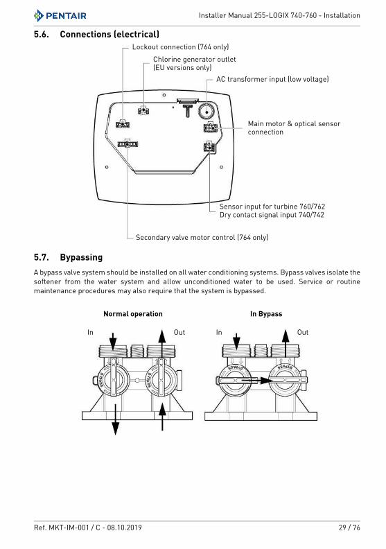
5.6. Connections (electrical)
5.7. Bypassing A bypass valve system should be installed on all water conditioning systems. Bypass valves isolate the softener from the water system and allow unconditioned water to be used. Service or routine maintenance procedures may also require that the system is bypassed.
Chlorine generator outlet(EU versions only)
AC transformer input (low voltage)
Lockout connection (764 only)
Main motor & optical sensor connection
Sensor input for turbine 760/762Dry contact signal input 740/742
Secondary valve motor control (764 only)
Normal operation In Bypass
In InOut Out
Installer Manual 255-LOGIX 740-760 - Installation
30 / 76 Ref. MKT-IM-001 / C - 08.10.2019
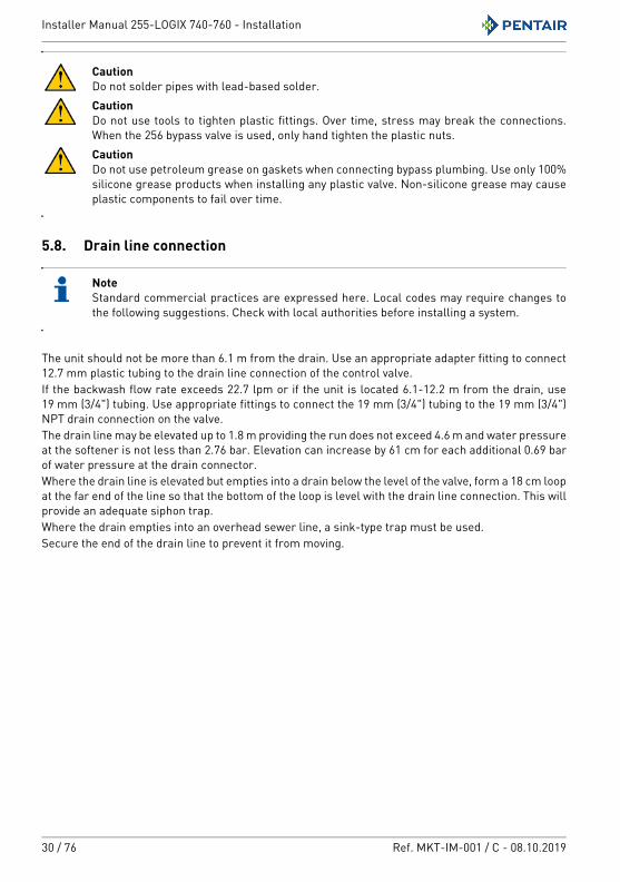
CautionDo not solder pipes with lead-based solder.CautionDo not use tools to tighten plastic fittings. Over time, stress may break the connections. When the 256 bypass valve is used, only hand tighten the plastic nuts.CautionDo not use petroleum grease on gaskets when connecting bypass plumbing. Use only 100% silicone grease products when installing any plastic valve. Non-silicone grease may cause plastic components to fail over time.
5.8. Drain line connection
NoteStandard commercial practices are expressed here. Local codes may require changes to the following suggestions. Check with local authorities before installing a system.
The unit should not be more than 6.1 m from the drain. Use an appropriate adapter fitting to connect 12.7 mm plastic tubing to the drain line connection of the control valve.If the backwash flow rate exceeds 22.7 lpm or if the unit is located 6.1-12.2 m from the drain, use 19 mm (3/4") tubing. Use appropriate fittings to connect the 19 mm (3/4") tubing to the 19 mm (3/4") NPT drain connection on the valve.The drain line may be elevated up to 1.8 m providing the run does not exceed 4.6 m and water pressure at the softener is not less than 2.76 bar. Elevation can increase by 61 cm for each additional 0.69 bar of water pressure at the drain connector.Where the drain line is elevated but empties into a drain below the level of the valve, form a 18 cm loop at the far end of the line so that the bottom of the loop is level with the drain line connection. This will provide an adequate siphon trap.Where the drain empties into an overhead sewer line, a sink-type trap must be used.Secure the end of the drain line to prevent it from moving.
Installer Manual 255-LOGIX 740-760 - Installation
Ref. MKT-IM-001 / C - 08.10.2019 31 / 76
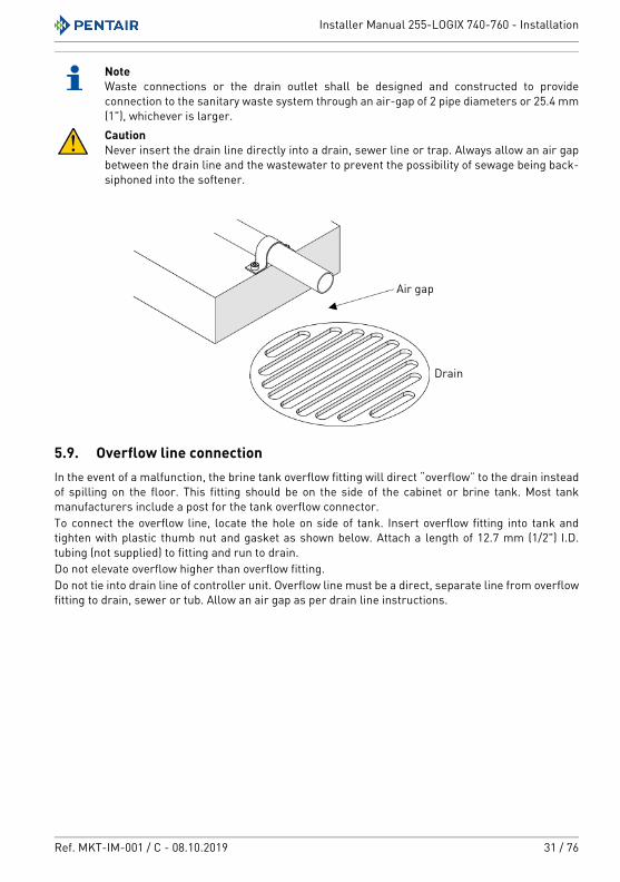
NoteWaste connections or the drain outlet shall be designed and constructed to provide connection to the sanitary waste system through an air-gap of 2 pipe diameters or 25.4 mm (1"), whichever is larger.CautionNever insert the drain line directly into a drain, sewer line or trap. Always allow an air gap between the drain line and the wastewater to prevent the possibility of sewage being back-siphoned into the softener.
5.9. Overflow line connectionIn the event of a malfunction, the brine tank overflow fitting will direct “overflow” to the drain instead of spilling on the floor. This fitting should be on the side of the cabinet or brine tank. Most tank manufacturers include a post for the tank overflow connector.To connect the overflow line, locate the hole on side of tank. Insert overflow fitting into tank and tighten with plastic thumb nut and gasket as shown below. Attach a length of 12.7 mm (1/2") I.D. tubing (not supplied) to fitting and run to drain.Do not elevate overflow higher than overflow fitting.Do not tie into drain line of controller unit. Overflow line must be a direct, separate line from overflow fitting to drain, sewer or tub. Allow an air gap as per drain line instructions.
Drain
Air gap
Installer Manual 255-LOGIX 740-760 - Installation
32 / 76 Ref. MKT-IM-001 / C - 08.10.2019
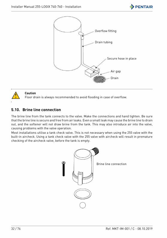
CautionFloor drain is always recommended to avoid flooding in case of overflow.
5.10. Brine line connectionThe brine line from the tank connects to the valve. Make the connections and hand tighten. Be sure that the brine line is secure and free from air leaks. Even a small leak may cause the brine line to drain out, and the softener will not draw brine from the tank. This may also introduce air into the valve, causing problems with the valve operation.Most installations utilise a tank check valve. This is not necessary when using the 255 valve with the built-in aircheck. Using a tank check valve with the 255 valve with aircheck will result in premature checking of the aircheck valve, before the tank is empty.
Drain tubing
Overflow fitting
Secure hose in place
Air gap
Drain
Brine line connection
Installer Manual 255-LOGIX 740-760 - Programming
Ref. MKT-IM-001 / C - 08.10.2019 33 / 76
6. Programming
6.1. Display
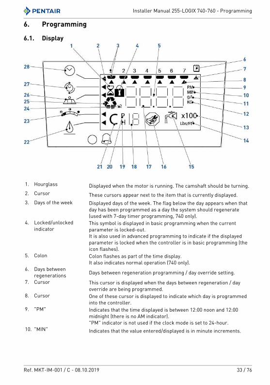
1. Hourglass Displayed when the motor is running. The camshaft should be turning.2. Cursor These cursors appear next to the item that is currently displayed.3. Days of the week Displayed days of the week. The flag below the day appears when that
day has been programmed as a day the system should regenerate (used with 7-day timer programming, 740 only).
4. Locked/unlocked indicator
This symbol is displayed in basic programming when the current parameter is locked-out.It is also used in advanced programming to indicate if the displayed parameter is locked when the controller is in basic programming (the icon flashes).
5. Colon Colon flashes as part of the time display.It also indicates normal operation (740 only).
6. Days between regenerations Days between regeneration programming / day override setting.
7. Cursor This cursor is displayed when the days between regeneration / day override are being programmed.
8. Cursor One of these cursor is displayed to indicate which day is programmed into the controller.
9. "PM" Indicates that the time displayed is between 12:00 noon and 12:00 midnight (there is no AM indicator)."PM" indicator is not used if the clock mode is set to 24-hour.
10. "MIN" Indicates that the value entered/displayed is in minute increments.
Installer Manual 255-LOGIX 740-760 - Programming
34 / 76 Ref. MKT-IM-001 / C - 08.10.2019
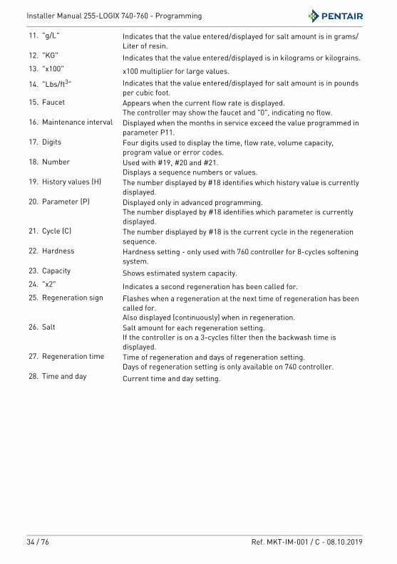
11. "g/L" Indicates that the value entered/displayed for salt amount is in grams/Liter of resin.
12. "KG" Indicates that the value entered/displayed is in kilograms or kilograins.13. "x100" x100 multiplier for large values.14. "Lbs/ft3" Indicates that the value entered/displayed for salt amount is in pounds
per cubic foot.15. Faucet Appears when the current flow rate is displayed.
The controller may show the faucet and "0", indicating no flow.16. Maintenance interval Displayed when the months in service exceed the value programmed in
parameter P11.17. Digits Four digits used to display the time, flow rate, volume capacity,
program value or error codes.18. Number Used with #19, #20 and #21.
Displays a sequence numbers or values.19. History values (H) The number displayed by #18 identifies which history value is currently
displayed.20. Parameter (P) Displayed only in advanced programming.
The number displayed by #18 identifies which parameter is currently displayed.
21. Cycle (C) The number displayed by #18 is the current cycle in the regeneration sequence.
22. Hardness Hardness setting - only used with 760 controller for 8-cycles softening system.
23. Capacity Shows estimated system capacity.24. "x2" Indicates a second regeneration has been called for.25. Regeneration sign Flashes when a regeneration at the next time of regeneration has been
called for.Also displayed (continuously) when in regeneration.
26. Salt Salt amount for each regeneration setting.If the controller is on a 3-cycles filter then the backwash time is displayed.
27. Regeneration time Time of regeneration and days of regeneration setting.Days of regeneration setting is only available on 740 controller.
28. Time and day Current time and day setting.
Installer Manual 255-LOGIX 740-760 - Programming
Ref. MKT-IM-001 / C - 08.10.2019 35 / 76
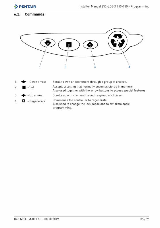
6.2. Commands
1. - Down arrow Scrolls down or decrement through a group of choices.
2. - Set Accepts a setting that normally becomes stored in memory.Also used together with the arrow buttons to access special features.
3. - Up arrow Scrolls up or increment through a group of choices.
4. - Regenerate Commands the controller to regenerate.Also used to change the lock mode and to exit from basic programming.
Installer Manual 255-LOGIX 740-760 - Programming
36 / 76 Ref. MKT-IM-001 / C - 08.10.2019
6.3. Basic programming
NoteMenus are displayed in a defined and incremental order.
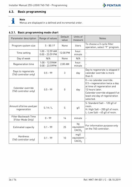
6.3.1. Basic programming mode chart
Parameter description Range of values Default value
Units of measure Notes
Program system size 5 - 80 / F None liters To choose a 3-cycle filter operation, select "F" program.
Time setting 1:00 - 12:59 AM0:00 - 23:59 PM 12:00 PM hour:
minute -
Day of week N/A None N/A -
Regeneration time 1:00 - 12:59AM0:00 - 23:59PM 2:00 AM hour:
minute -
Days to regenerate(740 controller only) 0.5 - 99 3 day
Day to regenerate is skipped if calendar override is more than 0.
Calendar override(760 controller only) 0.5 - 99 0 day
0 = no calendar override.0.5 = regeneration twice a day at time of regeneration and 12 hours later.Calendar override skipped if at least one day of regeneration selected.
Amount of brine used per regeneration S / H / L S g/l
S: Standard Salt – 120 g/l of resin.H: High Salt – 200 g/l of resin.L: Low Salt – 45 g/l of resin.
Filter Backwash Time(Filter Mode Only) 0 - 99 14 minute -
Estimated capacity 0.1 - 99 25kg
equivalent CACO3
For information purpose only on the 740 controller.
Hardness(760 controller only) 0.1 - 99 10
mg/l equivalent
CACO3
-
Installer Manual 255-LOGIX 740-760 - Programming
Ref. MKT-IM-001 / C - 08.10.2019 37 / 76
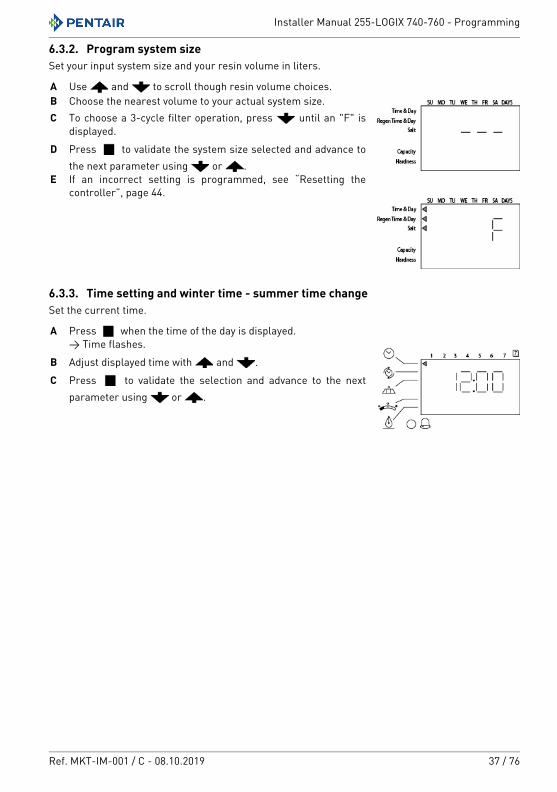
6.3.2. Program system sizeSet your input system size and your resin volume in liters.
6.3.3. Time setting and winter time - summer time changeSet the current time.
A Use and to scroll though resin volume choices.B Choose the nearest volume to your actual system size.C To choose a 3-cycle filter operation, press until an "F" is
displayed.D Press to validate the system size selected and advance to
the next parameter using or .E If an incorrect setting is programmed, see “Resetting the
controller”, page 44.
A Press when the time of the day is displayed.→ Time flashes.
B Adjust displayed time with and .C Press to validate the selection and advance to the next
parameter using or .
Installer Manual 255-LOGIX 740-760 - Programming
38 / 76 Ref. MKT-IM-001 / C - 08.10.2019
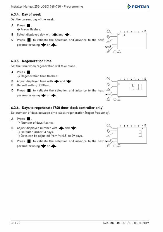
6.3.4. Day of weekSet the current day of the week.
6.3.5. Regeneration timeSet the time when regeneration will take place.
6.3.6. Days to regenerate (740 time-clock controller only)Set number of days between time-clock regeneration (regen frequency).
A Press .→ Arrow flashes.
B Select displayed day with and .C Press to validate the selection and advance to the next
parameter using or .
A Press .→ Regeneration time flashes.
B Adjust displayed time with and .C Default setting: 2:00am.D Press to validate the selection and advance to the next
parameter using or .
A Press .→ Number of days flashes.
B Adjust displayed number with and .→ Default number: 3 days.→ Days can be adjusted from ½ (0.5) to 99 days.
C Press to validate the selection and advance to the next parameter using or .
Installer Manual 255-LOGIX 740-760 - Programming
Ref. MKT-IM-001 / C - 08.10.2019 39 / 76
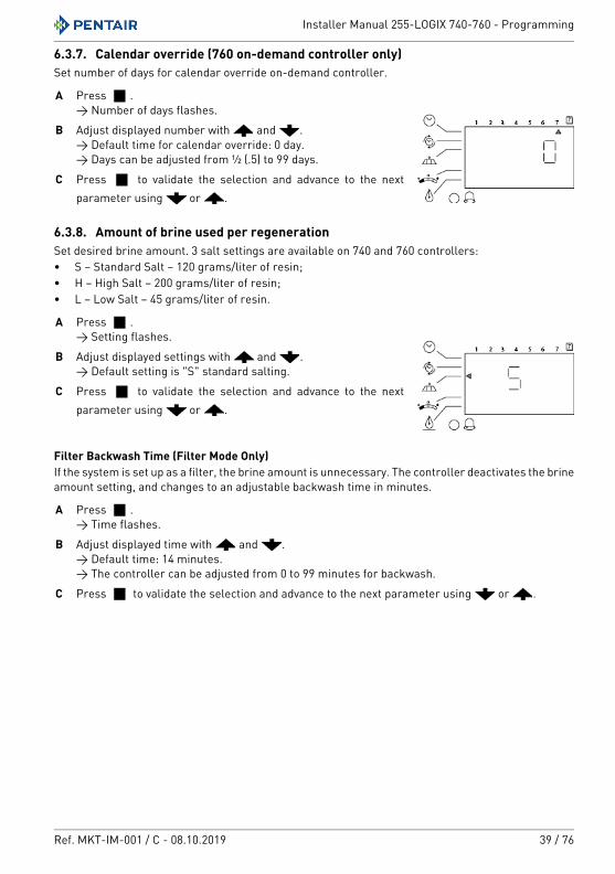
6.3.7. Calendar override (760 on-demand controller only)Set number of days for calendar override on-demand controller.
6.3.8. Amount of brine used per regenerationSet desired brine amount. 3 salt settings are available on 740 and 760 controllers:• S – Standard Salt – 120 grams/liter of resin;• H – High Salt – 200 grams/liter of resin;• L – Low Salt – 45 grams/liter of resin.
Filter Backwash Time (Filter Mode Only)If the system is set up as a filter, the brine amount is unnecessary. The controller deactivates the brine amount setting, and changes to an adjustable backwash time in minutes.
A Press .→ Number of days flashes.
B Adjust displayed number with and .→ Default time for calendar override: 0 day.→ Days can be adjusted from ½ (.5) to 99 days.
C Press to validate the selection and advance to the next parameter using or .
A Press .→ Setting flashes.
B Adjust displayed settings with and .→ Default setting is "S" standard salting.
C Press to validate the selection and advance to the next parameter using or .
A Press .→ Time flashes.
B Adjust displayed time with and .→ Default time: 14 minutes.→ The controller can be adjusted from 0 to 99 minutes for backwash.
C Press to validate the selection and advance to the next parameter using or .
Installer Manual 255-LOGIX 740-760 - Programming
40 / 76 Ref. MKT-IM-001 / C - 08.10.2019
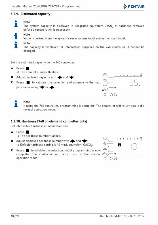
6.3.9. Estimated capacity
NoteThe system capacity is displayed in kilograms equivalent CaCO3 of hardness removed before a regeneration is necessary.NoteValue is derived from the system’s resin volume input and salt amount input.NoteThe capacity is displayed for information purposes on the 740 controller. It cannot be changed.
Set the estimated capacity on the 760 controller.
NoteIf using the 740 controller, programming is complete. The controller will return you to the normal operation mode.
6.3.10. Hardness (760 on-demand controller only)Set inlet water hardness at installation site.
A Press .→ The amount number flashes.
B Adjust displayed capacity with and .C Press to validate the selection and advance to the next
parameter using or .
A Press .→ The hardness number flashes.
B Adjust displayed hardness number with and .→ Default hardness setting is 10 mg/L equivalent CACO3.
C Press to validate the selection. Initial programming is now complete. The controller will return you to the normal operation mode.
Installer Manual 255-LOGIX 740-760 - Programming
Ref. MKT-IM-001 / C - 08.10.2019 41 / 76
6.4. Advanced programming
NotePress and hold + for 5 seconds to access advance programming. A "P" symbol is displayed on the bottom left of screen.
The 740/760 features an advanced programming level that allows the installing dealer to make changes to the controller for more demanding applications. The homeowner/end user should never have to access this level.
The advanced programming menus include:• P1 = Time of day;• P2 = Day of week;• P3 = Time of regeneration;• P4 = Number of days between regeneration (99 day calendar override);• P5 = (740 only);• P6 = Amount of brine used per regeneration or filter backwash time (1-99 minutes);• P7* = System capacity;• P8 = Hardness;• P9** = Units of measurement;• P10** = Clock mode.
* Calculated by software.** Pre-selected by World model (i.e. 230 Vac, 50 Hz, metrics unit).
Installer Manual 255-LOGIX 740-760 - Programming
42 / 76 Ref. MKT-IM-001 / C - 08.10.2019
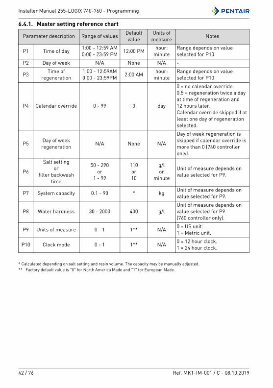
6.4.1. Master setting reference chart
* Calculated depending on salt setting and resin volume. The capacity may be manually adjusted.** Factory default value is "0" for North America Made and "1" for European Made.
Parameter description Range of values Default value
Units of measure Notes
P1 Time of day 1:00 - 12:59 AM0:00 - 23:59 PM 12:00 PM hour:
minuteRange depends on value selected for P10.
P2 Day of week N/A None N/A -
P3 Time of regeneration
1:00 - 12:59AM0:00 - 23:59PM 2:00 AM hour:
minuteRange depends on value selected for P10.
P4 Calendar override 0 - 99 3 day
0 = no calendar override.0.5 = regeneration twice a day at time of regeneration and 12 hours later.Calendar override skipped if at least one day of regeneration selected.
P5 Day of week regeneration N/A None N/A
Day of week regeneration is skipped if calendar override is more than 0 (740 controller only).
P6
Salt settingor
filter backwash time
50 - 290or
1 - 99
110or10
g/lor
minute
Unit of measure depends on value selected for P9.
P7 System capacity 0.1 - 90 * kg Unit of measure depends on value selected for P9.
P8 Water hardness 30 - 2000 400 g/lUnit of measure depends on value selected for P9 (760 controller only).
P9 Units of measure 0 - 1 1** N/A 0 = US unit.1 = Metric unit.
P10 Clock mode 0 - 1 1** N/A 0 = 12 hour clock.1 = 24 hour clock.
Installer Manual 255-LOGIX 740-760 - Programming
Ref. MKT-IM-001 / C - 08.10.2019 43 / 76
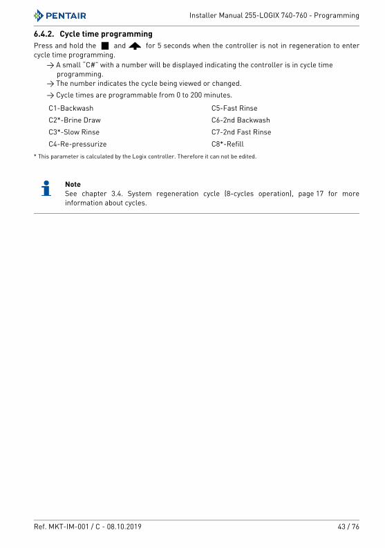
6.4.2. Cycle time programmingPress and hold the and for 5 seconds when the controller is not in regeneration to enter cycle time programming.
→ A small “C#” with a number will be displayed indicating the controller is in cycle time programming.
→ The number indicates the cycle being viewed or changed.→ Cycle times are programmable from 0 to 200 minutes.
* This parameter is calculated by the Logix controller. Therefore it can not be edited.
NoteSee chapter 3.4. System regeneration cycle (8-cycles operation), page 17 for more information about cycles.
C1-Backwash C5-Fast RinseC2*-Brine Draw C6-2nd BackwashC3*-Slow Rinse C7-2nd Fast RinseC4-Re-pressurize C8*-Refill
Installer Manual 255-LOGIX 740-760 - Programming
44 / 76 Ref. MKT-IM-001 / C - 08.10.2019
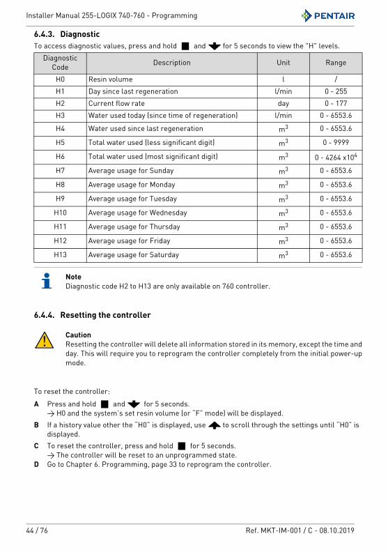
6.4.3. DiagnosticTo access diagnostic values, press and hold and for 5 seconds to view the "H" levels.
NoteDiagnostic code H2 to H13 are only available on 760 controller.
6.4.4. Resetting the controller
CautionResetting the controller will delete all information stored in its memory, except the time and day. This will require you to reprogram the controller completely from the initial power-up mode.
To reset the controller:A Press and hold and for 5 seconds.
→ H0 and the system’s set resin volume (or “F” mode) will be displayed.B If a history value other the “H0” is displayed, use to scroll through the settings until “H0” is
displayed.C To reset the controller, press and hold for 5 seconds.
→ The controller will be reset to an unprogrammed state.D Go to Chapter 6. Programming, page 33 to reprogram the controller.
Diagnostic Code Description Unit Range
H0 Resin volume l /H1 Day since last regeneration l/min 0 - 255H2 Current flow rate day 0 - 177H3 Water used today (since time of regeneration) l/min 0 - 6553.6
H4 Water used since last regeneration m3 0 - 6553.6
H5 Total water used (less significant digit) m3 0 - 9999
H6 Total water used (most significant digit) m3 0 - 4264 x104
H7 Average usage for Sunday m3 0 - 6553.6
H8 Average usage for Monday m3 0 - 6553.6
H9 Average usage for Tuesday m3 0 - 6553.6
H10 Average usage for Wednesday m3 0 - 6553.6
H11 Average usage for Thursday m3 0 - 6553.6
H12 Average usage for Friday m3 0 - 6553.6
H13 Average usage for Saturday m3 0 - 6553.6
Installer Manual 255-LOGIX 740-760 - Commissioning
Ref. MKT-IM-001 / C - 08.10.2019 45 / 76
7. Commissioning
NoteThis chapter is available for standard regeneration types. Contact your supplier if the actual regeneration is not standard and if you need assistance.
7.1. Water filling, draining and waterproofness inspection7.1.1. Activating the softenerAfter you have performed the previous initial programming steps, you will need to activate the softener.
CautionDo not rotate the camshaft by hand or damage to the unit may occur. Use the controller to take the camshaft electronically through the cycles.
Follow these steps carefully:1. Remove the cover from the valve. Removing the cover will allow you to see that the camshaft is
turning, and in which cycle the camshaft is currently positioned.2. With the supply water for the system still turned off, position the bypass valve to the "non-
bypass" (normal operation) position.3. Press on the controller for 5 seconds. This will initiate a manual regeneration.
The controller will indicate that the motor is turning the camshaft to cycle C1 (Backwash) position by flashing an hourglass. The controller will display the total regen time remaining. If you press and hold the button, the controller will indicate the time remaining in the current cycle.
4. Fill the media tank with water.→ While the controller is in cycle C1 (Backwash), open the water supply valve very slowly to
approximately the ¼ open position.
CautionIf opened too rapidly or too far, media may be lost out of the tank into the valve or the plumbing. In the ¼ open position, you should hear air slowly escaping from the valve drain line.
→ When all of the air has been purged from the media tank (water begins to flow steadily from the drain line), open the main supply valve all of the way. This will purge the final air from the tank.
→ Allow water to drain out until the water runs clear from the drain line. This purges any refuse from the media bed.
→ Turn off the water supply and let the system stand for about 5 minutes. This will allow any trapped air to escape from the tank.
Installer Manual 255-LOGIX 740-760 - Commissioning
46 / 76 Ref. MKT-IM-001 / C - 08.10.2019
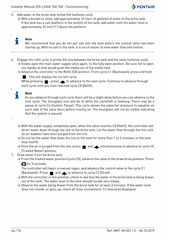
5. Add water to the brine tank (initial fill) (softener only).→ With a bucket or hose, add approximately 15 liters (4 gallons) of water to the brine tank.
If the tank has a salt platform in the bottom of the tank, add water until the water level is approximately 25 mm (1") above the platform.
NoteWe recommend that you do not put salt into the tank before the control valve has been started up. With no salt in the tank, it is much easier to view water flow and motion.
6. Engage the refill cycle to prime the line between the brine tank and the valve (softener only).→ Slowly open the main water supply valve again, to the fully open position. Be sure not to open
too rapidly as that would push the media out of the media tank.→ Advance the controller to the Refill (C8) position. From cycle C1 (Backwash), press and hold
. This will display the current cycle.While pressing , press to advance to the next cycle. Continue to advance through each cycle until you have reached cycle C8 (Refill).
NoteAs you advance through each cycle there will be a slight delay before you can advance to the next cycle. The hourglass icon will be lit while the camshaft is indexing. There may be a pause at cycle C4 (System Pause). This cycle allows the water/air pressure to equalize on each side of the valve discs before moving on. The hourglass will not be visible indicating that the system is paused.
→ With the water supply completely open, when the valve reaches C8 (Refill), the controller will direct water down through the line to the brine tank. Let the water flow through the line until all air bubbles have been purged from the line.
→ Do not let the water flow down the line to the tank for more than 1 to 2 minutes, or the tank may overfill.
→ Once the air is purged from the line, press and simultaneously to advance to cycle C0 (Treated Water) position.
7. Draw water from the brine tank.→ From the treated water position (cycle C0), advance the valve to the draw brine position. Press
for 5 seconds.The controller will begin a manual regen, and advance the control valve to the cycle C1 (Backwash). Press and to advance to cycle C2 (Draw).
→ With the controller in this position, check to see that the water in the brine tank is being drawn out of the tank. The water level in the tank should recede very slowly.
→ Observe the water being drawn from the brine tank for at least 3 minutes. If the water level does not recede, or goes up, check all hose connections. C2 should be displayed.
Installer Manual 255-LOGIX 740-760 - Commissioning
Ref. MKT-IM-001 / C - 08.10.2019 47 / 76
8. If the water level is receding from the brine tank you can then advance the controller back to the treated water (C0) position by pressing and simultaneously to advance the controller to the C0 position.
9. Finally, turn on a faucet plumbed after the water softener. Run the faucet until the water runs clear. Add salt to the brine tank.
7.1.2. Additional tips• When the controller is first plugged in, it may display a flashing hourglass and the message
"Err 3", this means that the controller is rotating to the home position. If the "Err 2" is displayed, check that the incoming power frequency matches the controller;
• the preset default time of regeneration is 2:00 AM;• power supply: the world controller senses the electrical input and decides which is needed;• the 700 Series controller can be programmed to regenerate on specific days of the week;• if electrical power is not available, the camshaft can be rotated counter-clockwise by hand if the
motor is removed;• the 700 Series controllers send commands to the motor for camshaft movement. However,
water pressure/flow are required during the regeneration cycle for backwash, purge and refill, and brine draw to actually take place;
• make sure the control power source is plugged in. The transformer should be connected to a non-switched power source;
• you can start programming from the beginning by resetting the amount of media, see chapter 6.4.4. Resetting the controller, page 44.
7.2. Sanitization7.2.1. Disinfection of water softenersThe construction materials of the modern water softener will not support bacterial growth, nor will these materials contaminate a water supply. During normal use, a softener may become fouled with organic matter, or in some cases with bacteria from the water supply. This may result in an off-taste or odour in the water.Some softeners may need to be disinfected after installation and some softeners will require periodic disinfection during their normal lifetime.Depending on the conditions of use, the softener type, the type of ion exchanger, and the disinfectant available, a choice can be made among the following methods.
Installer Manual 255-LOGIX 740-760 - Commissioning
48 / 76 Ref. MKT-IM-001 / C - 08.10.2019
7.2.2. Sodium or calcium hypochloriteThese materials are satisfactory for use with polystyrene resins, synthetic gel zeolite, greensand and bentonites.
5.25% Sodium hypochloriteIf stronger solutions are used, such as those sold for commercial laundries, adjust the dosage accordingly.
DosagePolystyrene resin: set 1.25 mL fluid per 1 L of resin.Non-resinous exchangers: set 0.85 mL fluid per 1 L.
Brine tank softenersBackwash the softener and add the required amount of hypochlorite solution to the well of the brine tank. The brine tank should have water in it to permit the solution to be carried into the softener.Proceed with the normal regeneration.
Calcium hypochloriteCalcium hypochlorite, 70% available chlorine, is available in several forms including tablets and granules. These solid materials may be used directly without dissolving before use.
DosageMeasure two grains ~ 0.11 mL 1 L.
Brine tank softenersBackwash the softener and add the required amount of hypochlorite to the well of the brine tank. The brine tank should have water in it to permit the chlorine solution from being carried into the softener.Proceed with the normal regeneration.
7.2.3. Electro chlorinationValves or systems already equipped with an electrochlorinator device or system are supposed to be sanitized during the brine draw phase.
Installer Manual 255-LOGIX 740-760 - Operation
Ref. MKT-IM-001 / C - 08.10.2019 49 / 76
8. Operation
During a regeneration:• A "C#" is displayed to show the current cycle;• total regen time remaining is displayed on screen;• you can press and hold to show current cycle time remaining.
8.1. Recommendations• Use only regeneration salts designed for water softening EN973;• for optimal system operation, the use of clean salt and impurities free is recommended (for
example salt pellets);• do not use ice melt salt, block, or rock salts;• the sanitizing process (both with liquid and electrochlorination) may introduce chlorine
compounds which may reduce the lifetime of the ion exchange resins. Refer to media manufacturer specifications sheet for more information.
8.2. Manual regeneration
Mandatory The controller must be in service in order to enable this procedure.NoteThe unit returns to normal operation if no buttons are pressed within 30 seconds.
Manual delayed regenerationA Press once for delayed regeneration.
→ The regeneration will start on the scheduled time. See chapter 6.3. Basic programming, page 36.
→ A flashing regen symbol will be displayed.
NoteTo cancel: press again. The regen symbol disappears.
Immediate regenerationA Press and hold for 5 seconds to initiate immediate manual regeneration.
→ A solid regeneration icon will be displayed.→ Camshaft starts rotating to cycle C1.
Installer Manual 255-LOGIX 740-760 - Operation
50 / 76 Ref. MKT-IM-001 / C - 08.10.2019
Double regenerationA After an immediate regeneration has begun, press again to plan a second manual
regeneration.→ A flashing "x2" symbol indicates the second regeneration will start at the programmed
delayed regeneration time.
Immediate double regeneration A Press and hold to start the second regeneration immediately following the current
regeneration. → A solid "x2" symbol will be displayed.
8.3. To advance regeneration cyclesA Simultaneously press and to advance to the next cycle.
→ An hourglass will display while the camshaft is moving.→ When the camshaft reaches next cycle, "C2” will be displayed.
B Repeat and to advance through each cycle.
8.4. To cancel a regenerationA Press and hold and for 5 seconds to cancel the regen.
→ Hourglass will flash once cancelled.→ Camshaft will move to service position – may take 1 to 2 minutes.

Installer Manual 255-LOGIX 740-760 - Maintenance
Ref. MKT-IM-001 / C - 08.10.2019 51 / 76
9. Maintenance
MandatoryCleaning and maintenance shall take place at regular intervals in order to guarantee the proper functioning of the complete system, and be documented in the Maintenance chapter in the User Guide document.MandatoryThe maintenance and service operation must be done by qualified personnel only. Failure in respecting this may void the warranty.
9.1. General system inspection
MandatoryHas to be done once a year at minimum.
9.1.1. Water quality1. Raw water total hardness.2. Treated water hardness.
9.1.2. Mechanical Checks1. Inspect general condition of valve and associated ancillaries and check for any leaks, ensure
valve connection to piping is made with adequate flexibility as per manufacturer instruction.2. Inspection of electrical connections, verify wiring connections and search for evidence of
overloading.3. Verify settings of electronic or electromechanical timer, verify regeneration frequency, make
sure the valve configuration correspond to the settings.4. Check water meter, if present, report water meter settings, compare with previous inspection.5. Verify total water consumption compared to previous visit.6. If pressure gauges are installed before and after softening system, verify and record static and
dynamic pressure, reporting pressure drop. Verify that inlet pressure respects valve and softening system limits.
7. If pressure gauges are not present, but suitable points exist, install temporary pressure gauge(s) to perform point 6.
Installer Manual 255-LOGIX 740-760 - Maintenance
52 / 76 Ref. MKT-IM-001 / C - 08.10.2019
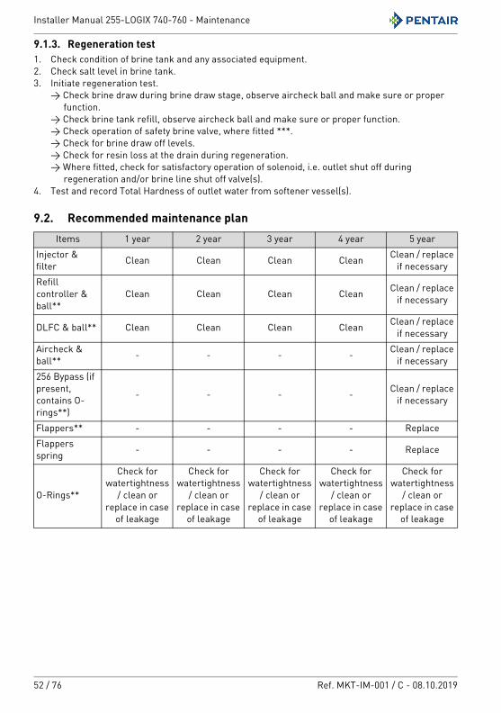
9.1.3. Regeneration test1. Check condition of brine tank and any associated equipment.2. Check salt level in brine tank.3. Initiate regeneration test.
→ Check brine draw during brine draw stage, observe aircheck ball and make sure or proper function.
→ Check brine tank refill, observe aircheck ball and make sure or proper function.→ Check operation of safety brine valve, where fitted ***.→ Check for brine draw off levels.→ Check for resin loss at the drain during regeneration.→ Where fitted, check for satisfactory operation of solenoid, i.e. outlet shut off during
regeneration and/or brine line shut off valve(s).4. Test and record Total Hardness of outlet water from softener vessel(s).
9.2. Recommended maintenance planItems 1 year 2 year 3 year 4 year 5 year
Injector & filter Clean Clean Clean Clean Clean / replace
if necessaryRefill controller & ball**
Clean Clean Clean Clean Clean / replace if necessary
DLFC & ball** Clean Clean Clean Clean Clean / replace if necessary
Aircheck & ball** - - - - Clean / replace
if necessary256 Bypass (if present, contains O-rings**)
- - - - Clean / replace if necessary
Flappers** - - - - ReplaceFlappers spring - - - - Replace
O-Rings**
Check for watertightness
/ clean or replace in case
of leakage
Check for watertightness
/ clean or replace in case
of leakage
Check for watertightness
/ clean or replace in case
of leakage
Check for watertightness
/ clean or replace in case
of leakage
Check for watertightness
/ clean or replace in case
of leakage
Installer Manual 255-LOGIX 740-760 - Maintenance
Ref. MKT-IM-001 / C - 08.10.2019 53 / 76
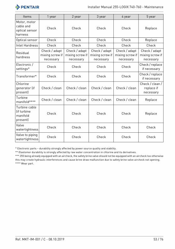
* Electronic parts – durability strongly affected by power source quality and stability.** Elastomer durability is strongly affected by raw water concentration in chlorine and its derivatives.*** 255 being already equipped with an aircheck, the safety brine valve should not be equipped with an aircheck too otherwise this may create hydraulic interferences and cause brine draw malfunction due to safety brine valve aircheck not opening.**** Wear part.
Motor, motor cable and optical sensor harness
Check Check Check Check Replace
Optical sensor Check Check Check Check ReplaceInlet Hardness Check Check Check Check Check
Residual hardness
Check / adapt mixing screw if
necessary
Check / adapt mixing screw if
necessary
Check / adapt mixing screw if
necessary
Check / adapt mixing screw if
necessary
Check / adapt mixing screw if
necessaryElectronic /settings* Check Check Check Check Check / replace
if necessary
Transformer* Check Check Check Check Check / replace if necessary
Chlorine generator (if present)
Check / clean Check / clean Check / clean Check / cleanCheck / clean /
replace if necessary
Turbine manifold**** Check / clean Check / clean Check / clean Check / clean Replace
Turbine cable (if turbine manifold present)
Check Check Check Check Replace
Valve watertightness Check Check Check Check Check
Valve to piping watertightness Check Check Check Check Check
Items 1 year 2 year 3 year 4 year 5 year
Installer Manual 255-LOGIX 740-760 - Maintenance
54 / 76 Ref. MKT-IM-001 / C - 08.10.2019
9.3. Recommendations9.3.1. Use original spare parts
CautionTo ensure correct operation and safety of the device, only use original spare parts and accessories recommended by the manufacturer.
Parts to keep in stock for potential replacements are motor and optical sensor, controller, transformer, injectors, flapper kit, O-ring kit, refill and DLFC.
9.3.2. Use original approved lubricants• Production:
PN 1014082 (NFO "Chemplex" 862 Silicone Comp.);• spare part:
PN 42561 (SILICONE LUBRICANT PACK).
9.3.3. Maintenance instructions• Disinfect and clean the system at least once a year or if the treated water has an off-taste or an
unusual odor;• perform a hardness test every year for softeners.
9.4. Cleaning and maintenance
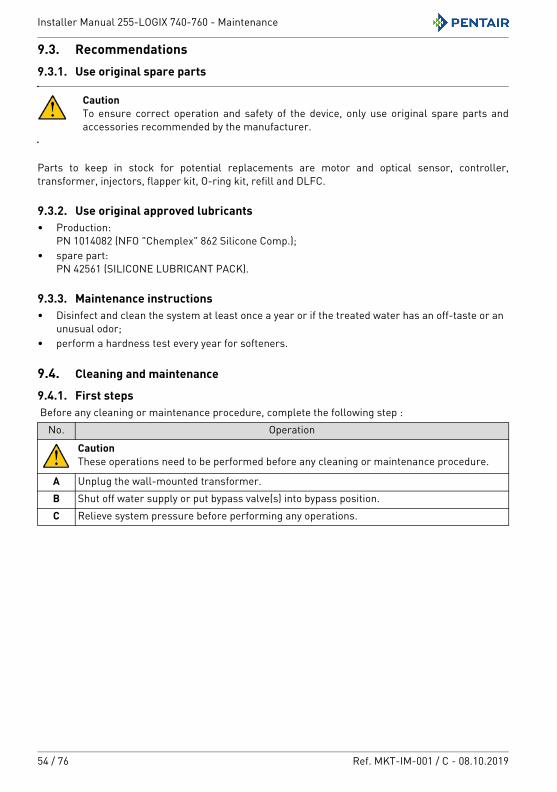
9.4.1. First steps Before any cleaning or maintenance procedure, complete the following step :
No. Operation
CautionThese operations need to be performed before any cleaning or maintenance procedure.
A Unplug the wall-mounted transformer.B Shut off water supply or put bypass valve(s) into bypass position.C Relieve system pressure before performing any operations.
Installer Manual 255-LOGIX 740-760 - Maintenance
Ref. MKT-IM-001 / C - 08.10.2019 55 / 76
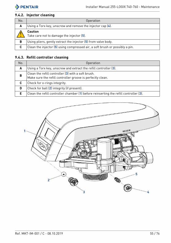
9.4.2. Injector cleaning
9.4.3. Refill controller cleaning
No. OperationA Using a Torx key, unscrew and remove the injector cap (4).
CautionTake care not to damage the injector (5).
B Using pliers, gently extract the injector (5) from valve body.C Clean the injector (5) using compressed air, a soft brush or possibly a pin.
No. OperationA Using a Torx key, unscrew and extract the refill controller (3).
B Clean the refill controller (3) with a soft brush.Make sure the refill controller groove is perfectly clean.
C Check for o-rings integrity.D Check for ball (2) integrity (if present).E Clean the refill controller chamber (1) before reinserting the refill controller (3).
Installer Manual 255-LOGIX 740-760 - Maintenance
56 / 76 Ref. MKT-IM-001 / C - 08.10.2019
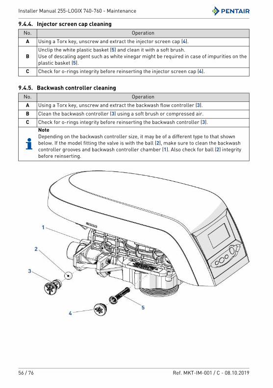
9.4.4. Injector screen cap cleaning
9.4.5. Backwash controller cleaning
No. OperationA Using a Torx key, unscrew and extract the injector screen cap (4).
BUnclip the white plastic basket (5) and clean it with a soft brush.Use of descaling agent such as white vinegar might be required in case of impurities on the plastic basket (5).
C Check for o-rings integrity before reinserting the injector screen cap (4).
No. OperationA Using a Torx key, unscrew and extract the backwash flow controller (3).B Clean the backwash controller (3) using a soft brush or compressed air. C Check for o-rings integrity before reinserting the backwash controller (3).
NoteDepending on the backwash controller size, it may be of a different type to that shown below. If the model fitting the valve is with the ball (2), make sure to clean the backwash controller grooves and backwash controller chamber (1). Also check for ball (2) integrity before reinserting.
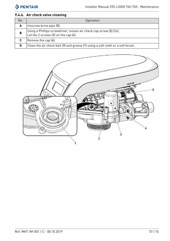
Installer Manual 255-LOGIX 740-760 - Maintenance
Ref. MKT-IM-001 / C - 08.10.2019 57 / 76
9.4.6. Air check valve cleaningNo. OperationA Unscrew brine pipe (5).
B Using a Phillips screwdriver, loosen air check cap screw (2) (2x).Let the 2 screws (2) on the cap (4).
C Remove the cap (4).D Clean the air check ball (3) and groove (1) using a soft cloth or a soft brush.
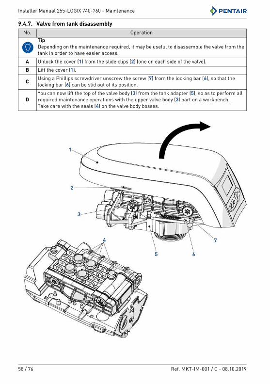
Installer Manual 255-LOGIX 740-760 - Maintenance
58 / 76 Ref. MKT-IM-001 / C - 08.10.2019
f9.4.7. Valve from tank disassembly No. Operation
TipDepending on the maintenance required, it may be useful to disassemble the valve from the tank in order to have easier access.
A Unlock the cover (1) from the slide clips (2) (one on each side of the valve).B Lift the cover (1).
C Using a Phillips screwdriver unscrew the screw (7) from the locking bar (6), so that the locking bar (6) can be slid out of its position.
DYou can now lift the top of the valve body (3) from the tank adapter (5), so as to perform all required maintenance operations with the upper valve body (3) part on a workbench.Take care with the seals (4) on the valve body bosses.
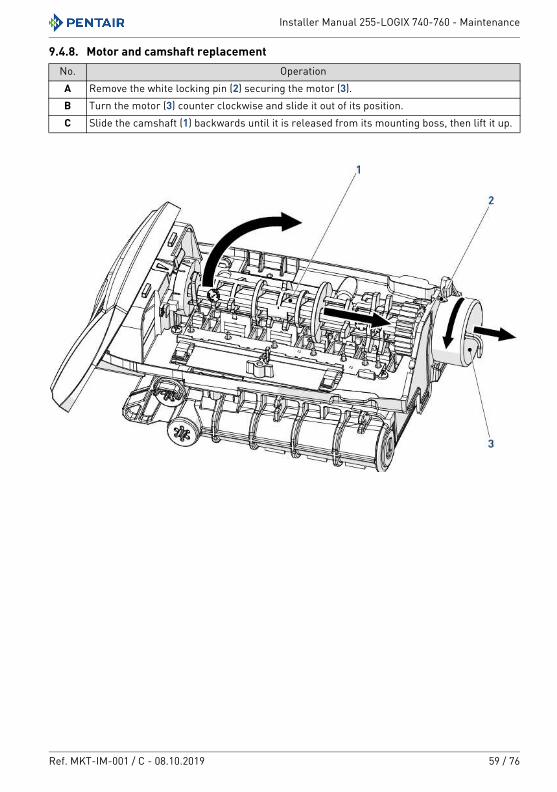
Installer Manual 255-LOGIX 740-760 - Maintenance
Ref. MKT-IM-001 / C - 08.10.2019 59 / 76
9.4.8. Motor and camshaft replacementNo. OperationA Remove the white locking pin (2) securing the motor (3).B Turn the motor (3) counter clockwise and slide it out of its position.C Slide the camshaft (1) backwards until it is released from its mounting boss, then lift it up.
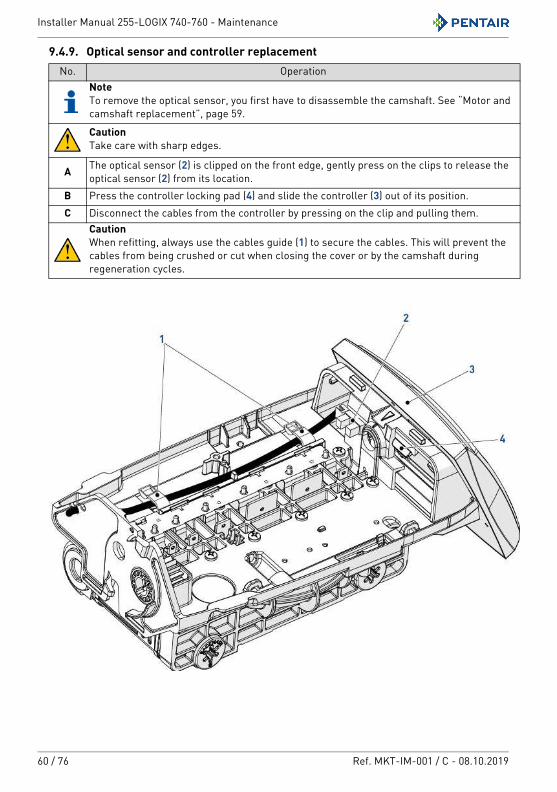
Installer Manual 255-LOGIX 740-760 - Maintenance
60 / 76 Ref. MKT-IM-001 / C - 08.10.2019
9.4.9. Optical sensor and controller replacementNo. Operation
NoteTo remove the optical sensor, you first have to disassemble the camshaft. See “Motor and camshaft replacement”, page 59.
CautionTake care with sharp edges.
A The optical sensor (2) is clipped on the front edge, gently press on the clips to release the optical sensor (2) from its location.
B Press the controller locking pad (4) and slide the controller (3) out of its position.C Disconnect the cables from the controller by pressing on the clip and pulling them.
CautionWhen refitting, always use the cables guide (1) to secure the cables. This will prevent the cables from being crushed or cut when closing the cover or by the camshaft during regeneration cycles.
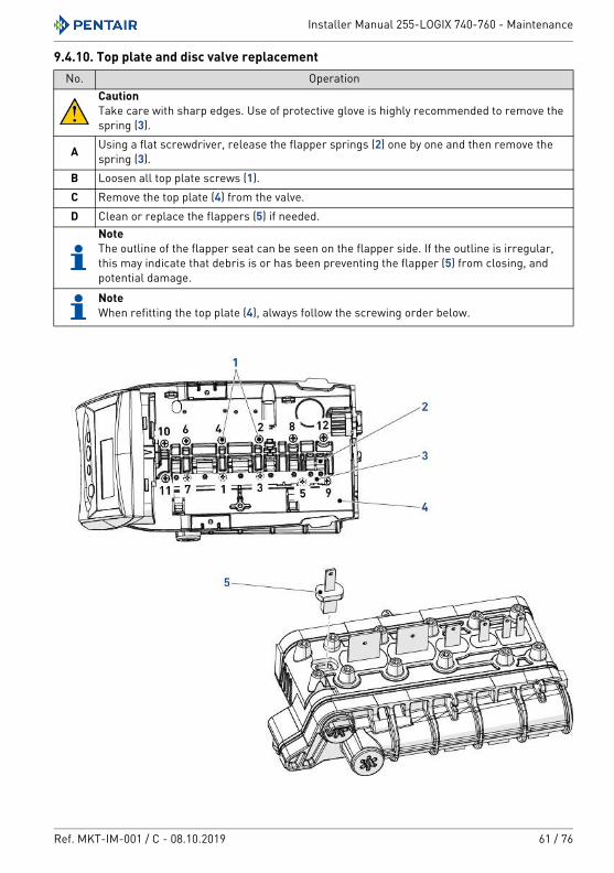
Installer Manual 255-LOGIX 740-760 - Maintenance
Ref. MKT-IM-001 / C - 08.10.2019 61 / 76
9.4.10. Top plate and disc valve replacementNo. Operation
CautionTake care with sharp edges. Use of protective glove is highly recommended to remove the spring (3).
A Using a flat screwdriver, release the flapper springs (2) one by one and then remove the spring (3).
B Loosen all top plate screws (1).C Remove the top plate (4) from the valve.D Clean or replace the flappers (5) if needed.
NoteThe outline of the flapper seat can be seen on the flapper side. If the outline is irregular, this may indicate that debris is or has been preventing the flapper (5) from closing, and potential damage.
NoteWhen refitting the top plate (4), always follow the screwing order below.
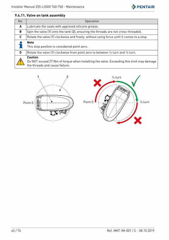
Installer Manual 255-LOGIX 740-760 - Maintenance
62 / 76 Ref. MKT-IM-001 / C - 08.10.2019
9.4.11. Valve on tank assemblyNo. OperationA Lubricate the seals with approved silicone grease.B Spin the valve (1) onto the tank (2), ensuring the threads are not cross-threaded.C Rotate the valve (1) clockwise and freely, without using force until it comes to a stop.
NoteThis stop position is considered point zero.
D Rotate the valve (1) clockwise from point zero to between ¼ turn and ½ turn.CautionDo NOT exceed 27 Nm of torque when installing the valve. Exceeding this limit may damage the threads and cause failure.
½ turn
¼ turn
Point 0Point 0
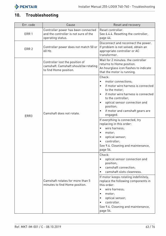
Installer Manual 255-LOGIX 740-760 - Troubleshooting
Ref. MKT-IM-001 / C - 08.10.2019 63 / 76
10. Troubleshooting
Err. code Cause Reset and recovery
ERR 1Controller power has been connected and the controller is not sure of the operating status.
Reset controller.See 6.4.4. Resetting the controller, page 44.
ERR 2 Controller power does not match 50 or 60 Hz.
Disconnect and reconnect the power.If problem is not solved, obtain an appropriate controller or AC transformer.
ERR3
Controller lost the position of camshaft. Camshaft should be rotating to find Home position.
Wait for 2 minutes: the controller returns to Home position.An hourglass icon flashes to indicate that the motor is running.
Camshaft does not rotate.
Check:• motor connections;• if motor wire harness is connected
to the motor;• if motor wire harness is connected
to the controller;• optical sensor connection and
position;• if motor and camshaft gears are
engaged.If everything is connected, try replacing in this order:• wire harness;• motor;• optical sensor;• controller;See 9.4. Cleaning and maintenance, page 54.
Camshaft rotates for more than 5 minutes to find Home position.
Check:• optical sensor connection and
position;• camshaft connection;• camshaft slots cleanness.If motor keeps rotating indefinitely, replace the following components in this order:• wire harness;• motor;• optical sensor;• controller.See 9.4. Cleaning and maintenance, page 54.
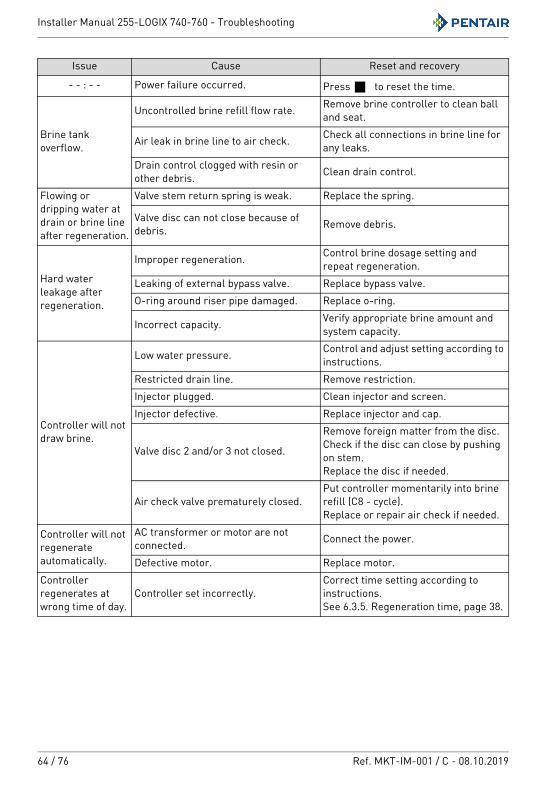
Installer Manual 255-LOGIX 740-760 - Troubleshooting
64 / 76 Ref. MKT-IM-001 / C - 08.10.2019
Issue Cause Reset and recovery
- - : - - Power failure occurred. Press to reset the time.
Brine tank overflow.
Uncontrolled brine refill flow rate. Remove brine controller to clean ball and seat.
Air leak in brine line to air check. Check all connections in brine line for any leaks.
Drain control clogged with resin or other debris. Clean drain control.
Flowing or dripping water at drain or brine line after regeneration.
Valve stem return spring is weak. Replace the spring.
Valve disc can not close because of debris. Remove debris.
Hard water leakage after regeneration.
Improper regeneration. Control brine dosage setting and repeat regeneration.
Leaking of external bypass valve. Replace bypass valve.O-ring around riser pipe damaged. Replace o-ring.
Incorrect capacity. Verify appropriate brine amount and system capacity.
Controller will not draw brine.
Low water pressure. Control and adjust setting according to instructions.
Restricted drain line. Remove restriction.Injector plugged. Clean injector and screen.Injector defective. Replace injector and cap.
Valve disc 2 and/or 3 not closed.
Remove foreign matter from the disc. Check if the disc can close by pushing on stem.Replace the disc if needed.
Air check valve prematurely closed.Put controller momentarily into brine refill (C8 - cycle).Replace or repair air check if needed.
Controller will not regenerate automatically.
AC transformer or motor are not connected. Connect the power.
Defective motor. Replace motor.Controller regenerates at wrong time of day.
Controller set incorrectly.Correct time setting according to instructions.See 6.3.5. Regeneration time, page 38.
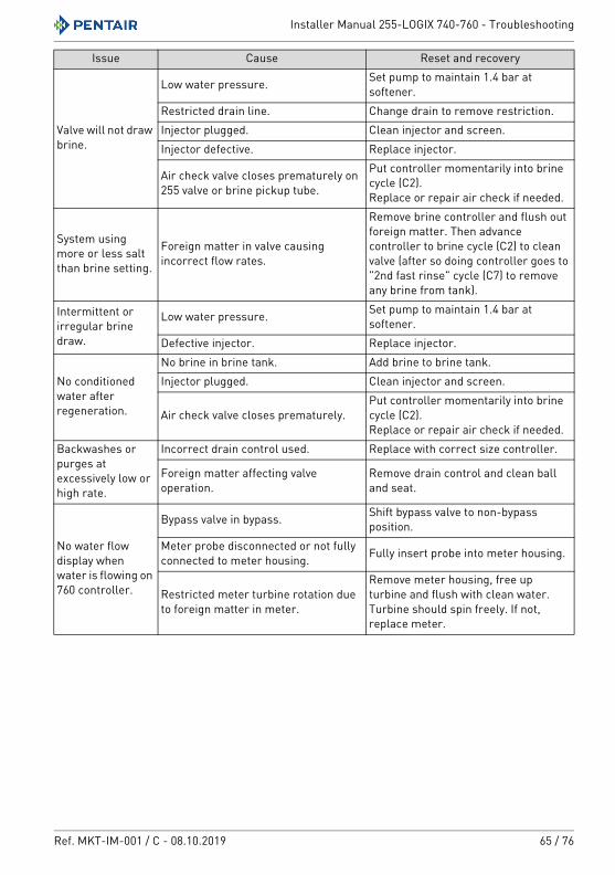
Installer Manual 255-LOGIX 740-760 - Troubleshooting
Ref. MKT-IM-001 / C - 08.10.2019 65 / 76
Valve will not draw brine.
Low water pressure. Set pump to maintain 1.4 bar at softener.
Restricted drain line. Change drain to remove restriction.Injector plugged. Clean injector and screen.Injector defective. Replace injector.
Air check valve closes prematurely on 255 valve or brine pickup tube.
Put controller momentarily into brine cycle (C2).Replace or repair air check if needed.
System using more or less salt than brine setting.
Foreign matter in valve causing incorrect flow rates.
Remove brine controller and flush out foreign matter. Then advance controller to brine cycle (C2) to clean valve (after so doing controller goes to "2nd fast rinse" cycle (C7) to remove any brine from tank).
Intermittent or irregular brine draw.
Low water pressure. Set pump to maintain 1.4 bar at softener.
Defective injector. Replace injector.
No conditioned water after regeneration.
No brine in brine tank. Add brine to brine tank.Injector plugged. Clean injector and screen.
Air check valve closes prematurely.Put controller momentarily into brine cycle (C2).Replace or repair air check if needed.
Backwashes or purges at excessively low or high rate.
Incorrect drain control used. Replace with correct size controller.
Foreign matter affecting valve operation.
Remove drain control and clean ball and seat.
No water flow display when water is flowing on 760 controller.
Bypass valve in bypass. Shift bypass valve to non-bypass position.
Meter probe disconnected or not fully connected to meter housing. Fully insert probe into meter housing.
Restricted meter turbine rotation due to foreign matter in meter.
Remove meter housing, free up turbine and flush with clean water. Turbine should spin freely. If not, replace meter.
Issue Cause Reset and recovery
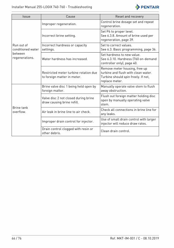
Installer Manual 255-LOGIX 740-760 - Troubleshooting
66 / 76 Ref. MKT-IM-001 / C - 08.10.2019
Run out of conditioned water between regenerations.
Improper regeneration. Control brine dosage set and repeat regeneration.
Incorrect brine setting.Set P6 to proper level.See 6.3.8. Amount of brine used per regeneration, page 39.
Incorrect hardness or capacity settings.
Set to correct values.See 6.3. Basic programming, page 36.
Water hardness has increased.Set hardness to new value.See 6.3.10. Hardness (760 on-demand controller only), page 40.
Restricted meter turbine rotation due to foreign matter in meter.
Remove meter housing, free up turbine and flush with clean water. Turbine should spin freely. If not, replace meter.
Brine tank overflow.
Brine valve disc 1 being held open by foreign matter.
Manually operate valve stem to flush away obstruction.
Valve disc 2 not closed during brine draw causing brine refill.
Flush out foreign matter holding disc open by manually operating valve stem.
Air leak in brine line to air check. Check all connections in brine line for any leaks.
Improper drain control for injector. Use of small drain control with larger injector will reduce draw rates.
Drain control clogged with resin or other debris. Clean drain control.
Issue Cause Reset and recovery
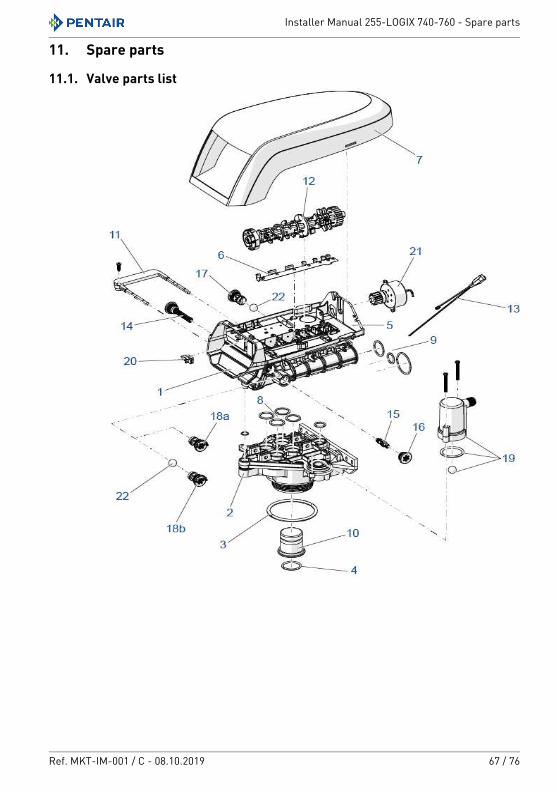
Installer Manual 255-LOGIX 740-760 - Spare parts
Ref. MKT-IM-001 / C - 08.10.2019 67 / 76
11. Spare parts
11.1. Valve parts list
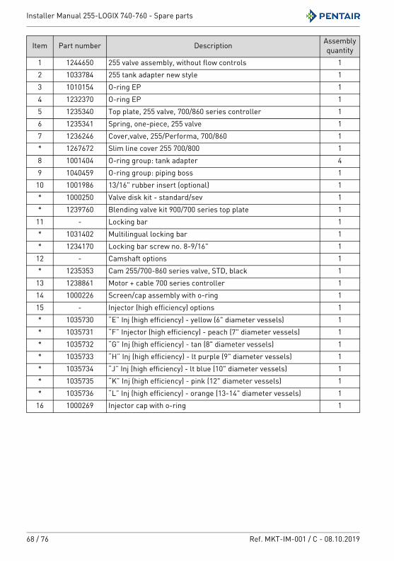
Installer Manual 255-LOGIX 740-760 - Spare parts
68 / 76 Ref. MKT-IM-001 / C - 08.10.2019
Item Part number Description Assembly quantity
1 1244650 255 valve assembly, without flow controls 12 1033784 255 tank adapter new style 13 1010154 O-ring EP 14 1232370 O-ring EP 15 1235340 Top plate, 255 valve, 700/860 series controller 16 1235341 Spring, one-piece, 255 valve 17 1236246 Cover,valve, 255/Performa, 700/860 1* 1267672 Slim line cover 255 700/800 18 1001404 O-ring group: tank adapter 49 1040459 O-ring group: piping boss 1
10 1001986 13/16" rubber insert (optional) 1* 1000250 Valve disk kit - standard/sev 1* 1239760 Blending valve kit 900/700 series top plate 1
11 - Locking bar 1* 1031402 Multilingual locking bar 1* 1234170 Locking bar screw no. 8-9/16" 1
12 - Camshaft options 1* 1235353 Cam 255/700-860 series valve, STD, black 1
13 1238861 Motor + cable 700 series controller 114 1000226 Screen/cap assembly with o-ring 115 - Injector (high efficiency) options 1* 1035730 “E” Inj (high efficiency) - yellow (6" diameter vessels) 1* 1035731 “F” Injector (high efficiency) - peach (7" diameter vessels) 1* 1035732 “G” Inj (high efficiency) - tan (8" diameter vessels) 1* 1035733 “H” Inj (high efficiency) - lt purple (9" diameter vessels) 1* 1035734 “J” Inj (high efficiency) - lt blue (10" diameter vessels) 1* 1035735 “K” Inj (high efficiency) - pink (12" diameter vessels) 1* 1035736 “L” Inj (high efficiency) - orange (13-14" diameter vessels) 1
16 1000269 Injector cap with o-ring 1
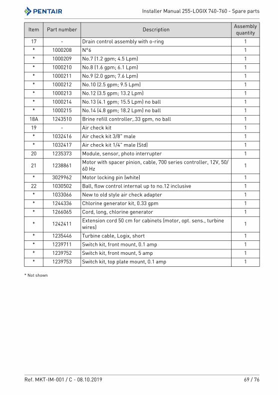
Installer Manual 255-LOGIX 740-760 - Spare parts
Ref. MKT-IM-001 / C - 08.10.2019 69 / 76
* Not shown
17 - Drain control assembly with o-ring 1* 1000208 N°6 1* 1000209 No.7 (1.2 gpm; 4.5 Lpm) 1* 1000210 No.8 (1.6 gpm; 6.1 Lpm) 1* 1000211 No.9 (2.0 gpm; 7.6 Lpm) 1* 1000212 No.10 (2.5 gpm; 9.5 Lpm) 1* 1000213 No.12 (3.5 gpm; 13.2 Lpm) 1* 1000214 No.13 (4.1 gpm; 15.5 Lpm) no ball 1* 1000215 No.14 (4.8 gpm; 18.2 Lpm) no ball 1
18A 1243510 Brine refill controller,.33 gpm, no ball 119 - Air check kit 1* 1032416 Air check kit 3/8" male 1* 1032417 Air check kit 1/4" male (Std) 1
20 1235373 Module, sensor, photo interrupter 1
21 1238861 Motor with spacer pinion, cable, 700 series controller, 12V, 50/60 Hz 1
* 3029962 Motor locking pin (white) 122 1030502 Ball, flow control internal up to no.12 inclusive 1* 1033066 New to old style air check adapter 1* 1244336 Chlorine generator kit, 0.33 gpm 1* 1266065 Cord, long, chlorine generator 1
* 1242411 Extension cord 50 cm for cabinets (motor, opt. sens., turbine wires) 1
* 1235446 Turbine cable, Logix, short 1* 1239711 Switch kit, front mount, 0.1 amp 1* 1239752 Switch kit, front mount, 5 amp 1* 1239753 Switch kit, top plate mount, 0.1 amp 1
Item Part number Description Assembly quantity
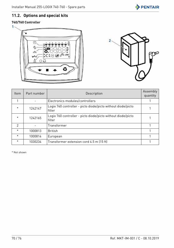
Installer Manual 255-LOGIX 740-760 - Spare parts
70 / 76 Ref. MKT-IM-001 / C - 08.10.2019
11.2. Options and special kits740/760 Controller
* Not shown
Item Part number Description Assembly quantity
1 - Electronics modules/controllers 1
* 1242147 Logix 740 controller - picto diode/picto without diode/picto filter 1
* 1242165 Logix 760 controller - picto diode/picto without diode/picto filter 1
2 - Transformer 1* 1000813 British 1* 1000814 European 1* 1030234 Transformer extension cord 4.5 m (15 ft) 1
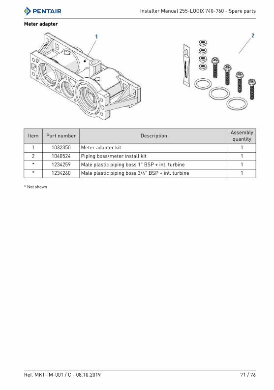
Installer Manual 255-LOGIX 740-760 - Spare parts
Ref. MKT-IM-001 / C - 08.10.2019 71 / 76
Meter adapter
* Not shown
Item Part number Description Assembly quantity
1 1032350 Meter adapter kit 12 1040524 Piping boss/meter install kit 1* 1234259 Male plastic piping boss 1" BSP + int. turbine 1* 1234260 Male plastic piping boss 3/4" BSP + int. turbine 1
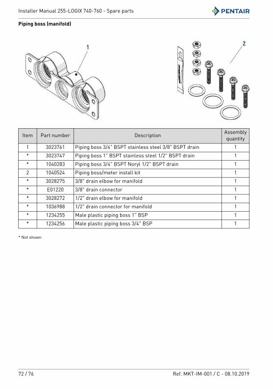
Installer Manual 255-LOGIX 740-760 - Spare parts
72 / 76 Ref. MKT-IM-001 / C - 08.10.2019
Piping boss (manifold)
* Not shown
Item Part number Description Assembly quantity
1 3023761 Piping boss 3/4" BSPT stainless steel 3/8" BSPT drain 1* 3023747 Piping boss 1" BSPT stainless steel 1/2" BSPT drain 1* 1040283 Piping boss 3/4" BSPT Noryl 1/2" BSPT drain 12 1040524 Piping boss/meter install kit 1* 3028275 3/8" drain elbow for manifold 1* E01220 3/8" drain connector 1* 3028272 1/2" drain elbow for manifold 1* 1036988 1/2" drain connector for manifold 1* 1234255 Male plastic piping boss 1" BSP 1* 1234256 Male plastic piping boss 3/4" BSP 1
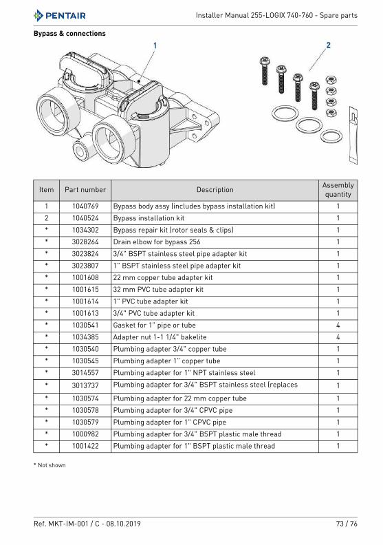
Installer Manual 255-LOGIX 740-760 - Spare parts
Ref. MKT-IM-001 / C - 08.10.2019 73 / 76
Bypass & connections
* Not shown
Item Part number Description Assembly quantity
1 1040769 Bypass body assy (includes bypass installation kit) 12 1040524 Bypass installation kit 1* 1034302 Bypass repair kit (rotor seals & clips) 1* 3028264 Drain elbow for bypass 256 1* 3023824 3/4" BSPT stainless steel pipe adapter kit 1* 3023807 1" BSPT stainless steel pipe adapter kit 1* 1001608 22 mm copper tube adapter kit 1* 1001615 32 mm PVC tube adapter kit 1* 1001614 1" PVC tube adapter kit 1* 1001613 3/4" PVC tube adapter kit 1* 1030541 Gasket for 1" pipe or tube 4* 1034385 Adapter nut 1-1 1/4" bakelite 4* 1030540 Plumbing adapter 3/4" copper tube 1* 1030545 Plumbing adapter 1" copper tube 1* 3014557 Plumbing adapter for 1" NPT stainless steel 1
* 3013737 Plumbing adapter for 3/4" BSPT stainless steel (replaces 1
* 1030574 Plumbing adapter for 22 mm copper tube 1* 1030578 Plumbing adapter for 3/4" CPVC pipe 1* 1030579 Plumbing adapter for 1" CPVC pipe 1* 1000982 Plumbing adapter for 3/4" BSPT plastic male thread 1* 1001422 Plumbing adapter for 1" BSPT plastic male thread 1
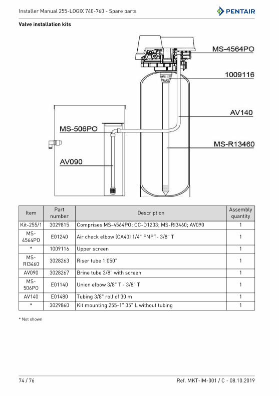
Installer Manual 255-LOGIX 740-760 - Spare parts
74 / 76 Ref. MKT-IM-001 / C - 08.10.2019
Valve installation kits
* Not shown
Item Part number Description Assembly
quantityKit-255/1 3029815 Comprises MS-4564PO; CC-D1203; MS-RI3460; AV090 1
MS-4564PO E01240 Air check elbow (CA40) 1/4" FNPT- 3/8" T 1
* 1009116 Upper screen 1MS-
RI3460 3028263 Riser tube 1.050" 1
AV090 3028267 Brine tube 3/8" with screen 1MS-
506PO E01140 Union elbow 3/8" T - 3/8" T 1
AV140 E01480 Tubing 3/8" roll of 30 m 1* 3029860 Kit mounting 255-1" 35" L without tubing 1
Installer Manual 255-LOGIX 740-760 - Disposal
Ref. MKT-IM-001 / C - 08.10.2019 75 / 76
12. Disposal
The device must be scrapped in accordance with directive 2012/19/EU or the environmental standards in force in the country of installation. The components included in the system must be separated and recycled in a waste recycling center that conforms with the legislation in force in the country of installation. This will help to reduce the impact on the environment, health, safety and help to promote recycling. Pentair does not collect used product for recycling. Contact your local recycling center for more information.

www.pentairaquaeurope.com