Embed Size (px)
Citation preview

Manufacturer reserves the right to discontinue, or change at any time, specifications or designs without notice and without incurring obligations.PC 111 Catalog No. 535-00091 Printed in U.S.A. Form 50-9SI Pg 1 11-02 Replaces: NewBook 1 4
Tab 5a 5a
Installation, Start-Up andConfiguration Instructions
CONTENTSPage
SAFETY CONSIDERATIONS . . . . . . . . . . . . . . . . . . . . . . 1GENERAL . . . . . . . . . . . . . . . . . . . . . . . . . . . . . . . . . . . . . . . . 1 INSTALLATION . . . . . . . . . . . . . . . . . . . . . . . . . . . . . . . . . 1-8Inspection. . . . . . . . . . . . . . . . . . . . . . . . . . . . . . . . . . . . . . . . 1PremierLink Controller Hardware. . . . . . . . . . . . . . . . . 1Field-Supplied Hardware . . . . . . . . . . . . . . . . . . . . . . . . . 2• SPACE TEMPERATURE (SPT) SENSOR• INDOOR AIR QUALITY CO2 SENSORPremierLink Controller Inputs and Outputs . . . . . . 3 Control Wiring. . . . . . . . . . . . . . . . . . . . . . . . . . . . . . . . . . . . 3Install Sensors . . . . . . . . . . . . . . . . . . . . . . . . . . . . . . . . . . . 4 • SPACE TEMPERATURE (SPT) SENSOR
INSTALLATION• INDOOR AIR QUALITY CO2 SENSOR
INSTALLATIONConnect to CCN Communication Bus . . . . . . . . . . . . 8 • COMMUNICATIONS BUS WIRE
SPECIFICATIONSSTART-UP . . . . . . . . . . . . . . . . . . . . . . . . . . . . . . . . . . . . . . .8,9Perform System Check-Out . . . . . . . . . . . . . . . . . . . . . . 8 Initial Operation and Test. . . . . . . . . . . . . . . . . . . . . . . . . 8Install Navigator . . . . . . . . . . . . . . . . . . . . . . . . . . . . . . . . . 8Password Protection . . . . . . . . . . . . . . . . . . . . . . . . . . . . . 9Forcing Values and Configuring Items . . . . . . . . . . . 9 CONFIGURATION . . . . . . . . . . . . . . . . . . . . . . . . . . . . 10-24Points Display Screen . . . . . . . . . . . . . . . . . . . . . . . . . . . 10Thermostat Control Input Screen. . . . . . . . . . . . . . . . 12 Alarm Service Configuration Screen . . . . . . . . . . . . 12Controller Identification Screen . . . . . . . . . . . . . . . . . 13Holiday Configuration Screen . . . . . . . . . . . . . . . . . . . 13Occupancy Configuration Screen . . . . . . . . . . . . . . . 13Set Point Screen . . . . . . . . . . . . . . . . . . . . . . . . . . . . . . . . 14Service Configuration Selection Screen . . . . . . . . . 15 PremierLink Configuration Screen . . . . . . . . . . . . . . 18 Occupancy Maintenance Screen . . . . . . . . . . . . . . . . 20Maintenance Screen . . . . . . . . . . . . . . . . . . . . . . . . . . . . 22
SAFETY CONSIDERATIONS
GENERAL
The PremierLink Controller is a factory-installed controlcompatible with the Carrier Comfort Network (CCN). Thiscontrol is designed to allow users the access and ability tochange factory-defined settings thus expanding the function ofthe standard unit control board. The complete PremierLinkpackage consists of a factory-installed control circuit boardwith the Complete C unit controls, leaving water temperaturesensor, and discharge air sensor.
Carrier’s diagnostic standard tier display tools such asNavigator or Scrolling Marquee can be used with the Premier-Link controller. Access is available via an RJ-11 connection ora 3-wire connection to the communication bus. User interfacesavailable for use with the CCN system are PCs equipped withCarrier user interface software such as Service Tool, Comfort-VIEW™, or ComfortWORKS®. When used as part of theCCN, other devices such as the CCN data transfer, LinkageThermostat, or Comfort Controller can read data from or writedata to the PremierLink controller.
INSTALLATION
Inspection — Inspect unit contents for visual defects thatmay have occurred during shipping. If there is any damage,contact your local representative before proceeding.
PremierLink Controller Hardware — When a CCNsystem is installed, a factory-mounted PremierLink controlleris provided with the water source heat pump (WSHP) units.The package from the factory includes:• PremierLink controller.• Supply air temperature sensor.• Leaving water temperature sensor.PREMIERLINK CONTROLLER — PremierLink controllerscan be provided with any Aquazone™ water source heat pumpproduct by selecting this option in the model number nomen-clature. The PremierLink controller is provided with, and in-cludes all the features of, the Complete C unit controller. Thespecific functionality of PremierLink is described in detail indedicated Carrier literature. Factory-supplied wiring (exceptspace temperature sensor [SPT]) is illustrated in Fig. 1.
SAFETY NOTEAir-handling equipment will provide safe and reliable servicewhen operated within design specifications. The equipmentshould be operated and serviced only by authorized person-nel who have a thorough knowledge of system operation,safety devices and emergency procedures.Use good judgement when applying any manufacturer’sinstructions to avoid injury to personnel or damage to equip-ment and property.
Disconnect all power to the unit before performing mainte-nance or service. Unit may automatically start if power isnot disconnected. Electrical shock and personal injurycould result.
IMPORTANT: Verify that configurations for AC-HP andAuxout are correct for proper equipment operation. Seepage 18.
PremierLink™Water Source Heat Pump
Controller

2
SUPPLY AIR TEMPERATURE SENSOR — A factory-installed supply air temperature sensor is provided withPremierLink™ controller for the water source heat pumpequipment. The sensor is a 10k ohm thermistor, which isinstalled in and protected by a stainless steel housing probe.Probe size is 1/4 in. diameter by 1.5 in. long. Wire size and typeare 22 AWG (American Wire Gage), 7/30 copper wire, andPVC white, 2 conductors.LEAVING WATER TEMPERATURE SENSOR — A factory-installed leaving water temperature sensor is provided withPremierLink controller for the water source heat pump equip-ment. The sensor is a 10k ohm thermistor, which is installed inand protected by a stainless steel housing probe. Probe size is1/4 in. diameter by 1.5 in. long. Wire size and type are 22 AWG,7/30 copper wire, and PVC white, 2 conductors.
Field-Supplied Hardware — The PremierLink control-ler is configurable with the following field-supplied sensors:• space temperature sensor (33ZCT55SPT, 33ZCT56SPT, or
33ZCT58SPT) in sensor mode or thermostat mode foreconomizer control
• indoor air quality sensor (33ZCSENCO2, 33ZCT55CO2,33ZCT56CO2) required only for demand controlventilationFor specific details about sensors, refer to the literature
supplied with the sensor.
SPACE TEMPERATURE (SPT) SENSOR — A field-suppliedCarrier space temperature sensor is required to maintain thespace temperature in sensor mode. There are three sensors avail-able for this application:• 33ZCT55SPT, Space Temperature Sensor with Override
Button• 33ZCT56SPT, Space Temperature Sensor with Override
Button and Set Point Adjustment• 33ZCT58SPT, Communicating Room Sensor with Override
Button, Set Point Adjustment, and Manual Fan controlINDOOR AIR QUALITY CO2 SENSOR — An indoor airquality sensor is required for CO2 level monitoring. Threedifferent CO2 sensors are available for this application:• 33ZCSENCO2 sensor is an indoor, wall-mounted sensor
with an LED (light-emitting diode) display• 33ZCT55CO2 sensor is an indoor, wall-mounted sensor
without display. The CO2 sensor also includes a space tem-perature sensor with override button
• 33ZCT56CO2 sensor is an indoor, wall-mounted sensorwithout display. The CO2 sensor also includes a space tem-perature sensor with override button and temperature offset
Y
W
O
G
R
C
AL1
AL2
A
CR
CMP1
FAN
PWR
HS1/EXH/RVS
PREMIERLINK
CR
COMPLETEC
CONTROL
J4J6 J5
J8J1
PW
R
SP
SA
LW
CM
PS
AF
E
T T T
LEGEND
NOTE: Reversing valve is on in Cooling mode.
CR — Control RelayLWT — Leaving Water Temperature SensorSAT — Supply Air Temperature SensorSPT — Space Temperature Sensor
Fig. 1 — Typical Factory-Installed PremierLink Wiring for WSHP Units(Except SPT Sensor — Field Installed)

3
PremierLink™ Controller Inputs and Outputs —The PremierLink controller inputs and outputs are shown inTable 1.
Control Wiring — The PremierLink controller can beconnected to either a Carrier-approved thermostat or CCNcompatible temperature sensor.
1. Turn off power to the control box.2. Strip the ends of the red, white, and black conductors of
the communication bus cable.
NOTE: When connecting the communication bus cable, acolor code system for the entire network is recommended tosimplify installation and checkout. See Table 2 for the rec-ommended color code.
3. Use 4-connector Molex with red, white and black wiresto connect the communication wires. Verify the colorcodes in Table 2 to ensure the Red (+) wire connectsto Terminal 1. Connect the White (ground) wire to Termi-nal 2. Connect the Black (–) wire to Terminal 3.
4. Secure all connections in Step 3 with wire nuts.5. Insert the plug into the existing 4-pin mating connector
on the base module in the main control box(Terminal J-2).
6. Restore power.
Table 1 — PremierLink Controller Inputs and Outputs
LEGEND
Table 2 — Color Code Recommendations
Disconnect electrical power before wiring the Premier-Link controller. Electrical shock, personal injury, ordamage to the PremierLink controller can result.
INPUTS POWER TERMINAL(S)SPACE TEMPERATURE (SPT) AI (10K Thermistor) J6-7, J6-6SET POINT ADJUSTMENT (STO) AI (10K Thermistor) J6-5, J6-6SUPPLY AIR TEMPERATURE (SAT) AI (10 K Thermistor) J6-3, J6-4LEAVING WATER TEMPERATURE AI (10K Thermistor) J6-1, J6-2IAQ SENSOR (IAQI) (4-20 mA) J5-5, J5-6OUTDOOR AQ SENSOR (OAQ) (NOT USED) (4-20 mA) J5-2, J5-3REMOTE TIME CLOCK (RMTOCC) DI (24 VAC) J4-11, J4-12COMPRESSOR LOCKOUT (CMPSAFE) DI (24 VAC) J4-9, J4-10FIRE SHUTDOWN (FSD) DI (24 VAC) J4-7, J4-8SUPPLY FAN STATUS (SFS) DI (24 VAC) J4-5, J4-6NOT USEDENTHALPY STATUS (ENTH) (NOT USED) DI (24 VAC) J4-1, J4-2
OUTPUTS POWER TERMINALSECONOMIZER (ECONPOS) (NOT USED) 4-20 mA J9-1, J9-2FAN (SF) DO Relay (24 VAC, 1A) J8-18COOL STAGE 1 (CMP1) DO Relay (24 VAC, 1A) J8-15COOL STAGE 2 (CMP2) DO Relay (24 VAC, 1A) J8-12HEAT STAGE 1 (HS1) DO Relay (24 VAC, 1A) J8-9HEAT STAGE 2 (HS2 DO Relay (24 VAC, 1A) J8-6HEAT 3/EXHAUST/REVERSING VALVE (HS3/EXH/RVS) DO Relay (24 VAC, 1A) J8-3
AI — Analog InputDI — Digital InputDO — Digital Output
SIGNAL TYPE CCN BUS WIRE COLOR CCN PLUG PIN NUMBER+ Red 1
Ground White 2– Black 3

4
Install Sensors (See Fig. 2-6) — The PremierLink™controller can be used with either the T58 Communicating sen-sor or any combination of CO2 and space temperature sensors.Refer to the instructions supplied with each sensor for electricalrequirements.NOTE: All space and indoor air quality sensors are field-installed accessories. SPACE TEMPERATURE (SPT) SENSOR INSTALLA-TION — There are three types of SPT sensors available fromCarrier: The 33ZCT55SPT space temperature sensor withtimed override button, the 33ZCT56SPT space temperaturesensor with timed override button and set point adjustment, andthe 33ZCT58SPT T58 communicating room sensor withtimed override button, set point adjustment, and manual fancontrol. See Fig. 2, 3 and 6 for sensor wiring.
The space temperature sensors are used to measure thebuilding interior temperature. The T58 communicating roomsensors measure and maintain room temperature by communi-cating with the controller. Sensors should be located on aninterior building wall. The sensor wall plate accommodatesthe NEMA (National Electrical Manufacturers Association)standard 2 x 4 junction box. The sensor can be mounted direct-ly on the wall surface if acceptable by local codes.
Do not mount the sensor in drafty locations such as near airconditioning or heating ducts, over heat sources such as base-board heaters, radiators, or directly above wall-mounted light-ing dimmers. Do not mount the sensor near a window whichmay be opened, near a wall corner, or a door. Sensors mountedin these areas will have inaccurate and erratic sensor readings.
The sensor should be mounted approximately 5 ft from thefloor, in an area representing the average temperature in thespace. Allow at least 4 ft between the sensor and any cornerand mount the sensor at least 2 ft from an open doorway. TheSPT sensor wires will be connected to terminals on the unitmain control board. Install the sensor as follows:
1. Locate the two Allen type screws at the bottom of thesensor.
2. Turn the two screws clockwise to release the cover fromthe sensor wall mounting plate.
3. Lift the cover from the bottom and then release it fromthe top fasteners.
4. Feed the wires from the electrical box through the open-ing in the center of the sensor mounting plate.
5. Using two no. 6-32 x 1 mounting screws (provided withthe sensor), secure the sensor to the electrical box.NOTE: The sensor may also be mounted directly onthe wall using 2 plastic anchors and 2 sheet metalscrews (field-supplied).
6. Use 20 gage wire to connect the sensor to the controller.The wire is suitable for distances of up to 500 ft. Use athree-conductor shielded cable for the sensor and setpoint adjustment connections. The standard CCNcommunication cable may be used. If the set point adjust-ment (slidebar) is not required, then an unshielded, 18 or20 gage, two-conductor, twisted pair cable may be used.The CCN network service jack requires a separate,shielded CCN communication cable. Always use sepa-rate cables for CCN communication and sensor wir-ing. (Refer to Fig. 2-4 for wire terminations.)
7. Replace the cover by inserting the cover at the top of themounting plate first, then swing the cover down over thelower portion. Rotate the two Allen head screws counter-clockwise until the cover is secured to the mounting plateand locked in position.
NOTE: See Table 3 for thermistor resistance vs temperaturevalues.Wiring the Space Temperature Sensor — To wire the sensor,perform the following (see Fig. 2-4):
1. Identify which cable is for the sensor wiring. 2. Strip back the jacket from the cables for at least 3 inches.
Strip 1/4-in. of insulation from each conductor. Cut theshield and drain wire from the sensor end of the cable.
3. Connect the sensor cable as follows:a. Connect one wire from the cable to (BLU) wire on
J6-7 analog connector on the controller. Connectthe other end of the wire to the left terminal on theSEN terminal block of the sensor.
b. Connect another wire from the cable to (BRN)J6-6 analog connector on the controller. Connectthe other end of the wire to the remaining open ter-minal on the SEN terminal block.
c. On 33ZCT56SPT thermostats, connect the remain-ing wire to the (BLK) STO on J6-5 connector onthe controller. Connect the other end of the wireto the right terminal on the SET terminal block ofthe sensor.
d. In the control box, install a no. 10 ring type crimplug on the shield drain wire. Install this lug underthe mounting screw of the PremierLink controller.
e. On 33ZCT56SPT thermostats install a jumperbetween the two center terminals (right SEN andleft SET). See Fig. 3.
f. Refer to Fig. 4 for 33ZCT58SPT thermostat wir-ing. Once the T58 sensor is powered up, all of thegraphic icons on the LCD display will be energizedfor a few seconds. The icons will then turn off andthe T58 sensor will energize the three-digitnumeric display. The value “58” will be displayedfor two seconds. After 2 seconds, the LCD will dis-play the default space temperature value.
NOTE: See Fig. 5 for space temperature sensor averaging.
Table 3 — Thermistor Resistance vs Temperature Values for Space Temperature Sensor,Supply Air Temperature Sensor, and
Outdoor Air Temperature Sensor
TEMP(C)
TEMP(F)
RESISTANCE(Ohms)
–40 –40 335,651–35 –31 242,195–30 –22 176,683–25 –13 130,243–20 –4 96,974–15 5 72,895–10 14 55,298
–5 23 42,3150 32 32,6515 41 25,395
10 50 19,90315 59 15,71420 68 12,49425 77 10,00030 86 8,05635 95 6,53040 104 5,32545 113 4,36750 122 3,60155 131 2,98560 140 2,48765 149 2,08270 158 1,752

5
INDOOR AIR QUALITY CO2 SENSOR INSTALLATION(IAQ) — The indoor air quality sensor accessory monitorscarbon dioxide (CO2) levels. This information is used to moni-tor IAQ levels. Three types of sensors are provided. The wallsensor can be used to monitor the conditioned air space.Sensors use infrared technology to measure the levels of CO2present in the air. The wall sensor is available with or withoutan LCD readout to display the CO2 level in ppm.
The CO2 sensors are all factory set for a range of 0 to2000 ppm and a linear mA output of 4 to 20. Refer to theinstructions supplied with the CO2 sensor for electrical require-ments and terminal locations.
To accurately monitor the quality of the air in the condi-tioned air space, locate the sensor near a return air grille (ifpresent) so it senses the concentration of CO2 leaving thespace. The sensor should be mounted in a location to avoiddirect breath contact.
Do not mount the IAQ sensor in drafty areas such as nearsupply ducts, open windows, fans, or over heat sources. Allowat least 3 ft between the sensor and any corner. Avoid mountingthe sensor where it is influenced by the supply air; the sensorgives inaccurate readings if the supply air is blown directly ontothe sensor or if the supply air does not have a chance to mixwith the room air before it is drawn into the return airstream.Wiring the Indoor Air Quality Sensor — To wire the sensorsafter they are mounted in the conditioned air space, see Fig. 6and the instructions shipped with the sensors. For each sensor,use two 2-conductor 18 AWG (American Wire Gage) twisted-pair cables (unshielded) to connect the separate isolated 24 vacpower source to the sensor and to connect the sensor to the con-trol board terminals. To connect the sensor to the control,identify the positive (4 to 20 mA) and ground (SIG COM) ter-minals on the sensor. Connect the 4-20 mA terminal to terminalIAQ (RED) and connect the SIG COM terminal to terminalGND (BRN).
2 3 4 5 61
SW1
SEN
BRN (GND)BLU (SPT)
RED(+)WHT(GND)
BLK(-) CCN COM
SENSOR WIRING
2 3 4 5 61
SW1
SEN SET
Cool Warm
BRN (GND)BLU (SPT)
RED(+)WHT(GND)
BLK(-) CCN COM
SENSOR WIRING
JUMPERTERMINALSAS SHOWN
BLK(T56)
Fig. 2 — Space Temperature SensorTypical Wiring (33ZCT55SPT)
Fig. 3 — Space Temperature SensorTypical Wiring (33ZCT56SPT)
VAC
24 VAC
BLACK (-)
WHITE (GND)
RED (+)
BLACK (-)
WHITE (GND)
RED (+)
CCNCOM
J2(COM)
COM
CCN-
GND
CCN+
T58 SENSOR
J6-6 SDT (COM)
J4-3 (24 VAC)
FIELD WIRING
Fig. 4 — T58 Communicating SensorTypical Wiring (33ZCT58SPT)

6
J66
7
RED
BLK
RED RED
BLK BLK
BLK
RED
BLK
RED
SENSOR 1 SENSOR 2 SENSOR 3 SENSOR 4
J6
6
7
RED
BLK
RED
BLK
SENSOR 2SENSOR 1
RED
RED
BLK
SENSOR 3
SENSOR 4
BLK
BLK
RE
D
RED RED
BLK BLK
SENSOR 8 SENSOR 9
SENSOR 5
RED
BLK
SENSOR 6
SENSOR 7
BLK
RE
D
SPACE TEMPERATURE AVERAGING — 4 SENSOR APPLICATION
SPACE TEMPERATURE AVERAGING — 9 SENSOR APPLICATION
Fig. 5 — Space Temperature Averaging
LEGEND
Factory Wiring
Field Wiring

7
Fig
. 6 —
Pre
mie
rLin
k™ C
on
tro
ller
and
Sen
sor
Wir
ing
— 3
3ZC
T55
SP
T, 3
3ZC
T56
SP
T, 3
3ZC
T58
SP
T S
pac
e Te
mp
erat
ure
Sen
sors
;33
ZC
SE
NC
O2
(Ou
tdo
or)
, an
d 3
3ZC
T55
CO
2, 3
3ZC
T56
CO
2 (I
nd
oo
r) A
ir Q
ual
ity
Sen
sors

8
Connect to CCN Communication Bus — ThePremierLink™ controller connects to the bus in a daisy chainarrangement. Negative pins on each component must beconnected to respective negative pins (and likewise positivepins on each component must be connected to respective posi-tive pins). The controller signal pins must be wired to the signalground pins. Wiring connections for CCN must be made at the3-pin plug.
At any baud (9600, 19200, 38400), the number of control-lers is limited to 239 devices maximum. Bus length may notexceed 4000 ft, with no more than 60 total devices on any1000-ft section. Optically isolated RS-485 repeaters arerequired every 1000 ft.NOTE: Carrier device default is 9600 baud.COMMUNICATION BUS WIRE SPECIFICATIONS —The CCN Communication Bus wiring is field-supplied andfield-installed. It consists of shielded three-conductor cablewith drain (ground) wire. The cable selected must be identicalto the CCN Communication Bus wire used for the entire net-work. See Table 4 for recommended cable.
Table 4 — Recommended Cables
NOTE: Conductors and drain wire must be at least 20 AWG,stranded, and tinned copper. Individual conductors must beinsulated with PVC, PVC/nylon, vinyl, Teflon, or polyethyl-ene. An aluminum/polyester 100% foil shield and an outerjacket of PVC, PVC/nylon, chrome vinyl, or Teflon with aminimum operating temperature range of –20 C to 60 C isrequired.
The communication bus shields must be tied together ateach system element. If the communication bus is entirelywithin one building, the resulting continuous shield must beconnected to ground at only one single point. If the communi-cation bus cable exits from one building and enters anotherbuilding, the shields must be connected to the grounds at alightning suppressor in each building (one point only).
START-UP
Use the Carrier network communication software to start upand configure the PremierLink™ controller.
Changes can be made using the ComfortWORKS® soft-ware, ComfortVIEW™ software, or Network Service Tool.The Network Service Tool is a portable interface device thatallows the user to change system set-up and set points from azone sensor or terminal control module. During start-up, theCarrier software can also be used to verify communicationwith PremierLink controller.NOTE: All set-up and set point configurations are factory-set and field-adjustable.
For specific operating instructions, refer to the literatureprovided with user interface software.
Perform System Check-Out1. Check the correctness and tightness of all power and
communication connections.2. At the unit, check fan and system controls for proper
operation.3. At the unit, check electrical system and connections of
any optional electric reheat coil.4. Check to be sure the area around the unit is clear of
construction dirt and debris.5. Check that final filters are installed in the unit. Dust and
debris can adversely affect system operation.6. Verify that the PremierLink controls are properly
connected to the CCN bus.
Initial Operation and Test — Perform the followingprocedure:
1. Apply 24 vac power to the control. 2. Connect the service tool to the phone jack service port of
the controller.3. Using the Service Tool, upload the controller from
address 0, 31 at 9600 baud rate. The address may be set atthis time. Make sure that Service Tool is connected toonly one unit when changing the address.
Install Navigator — The Navigator is a portable dis-play module that conforms to NEMA 4 specifications foroutdoor use in temperatures ranging from –22 F (–30 C) to158 F (70 C). The Navigator can be used to configure andperform service diagnostics on machines equipped with thePremierLink Controller. See Fig. 7.
The Navigator keypad contains eleven menu LEDs and oneAlarm Status LED, all of which are red. The Navigator is capa-ble of displaying four 24-character lines of information on abacklit liquid crystal display. The Navigator has four functionalkeys which are the up arrow ( ), down arrow ( ),
and keys.
INSTALLATION — The Navigator display module is intend-ed to be a mobile device, so there are no holes in the device forpermanent mounting. The module has a magnetic mount that isstrong enough to hold the device in place on any clean, drymetal surface.
MANUFACTURER CABLE PART NO.Alpha 2413 or 5463American A22503Belden 8772Columbia 02525
The unit must be electrically grounded in accordance withlocal codes and NEC ANSI/NFPA 70 (American NationalStandards Institute/National Fire Protection Association).
ENTER ESCAPE
Run StatusService TestTemperaturesPressures
SetpointsInputs
OutputsConfigurationTime Clock
Operating ModesAlarms
ENTER
E S C
M O D EAlarm Status
TIMEEWTLWTSETP
1 2 . 5 85 4 . 6 ° F4 4 . 1 ° F4 4 . 0 ° F
N A V I G A T O R
C o m f o r t L i n k
Fig. 7 — Navigator in Display Mode

9
To enter LEN (local equipment network) mode:1. Remove power by removing the connection to J1.2. Remove the connection to J2 (to avoid communication
problems with equipment).3. Position the DIP switch to 0 (ON) position.4. Restore power by reconnecting J1.5. Plug in the Navigator.The controller is now in LEN mode and will support the
Navigator device.To return to CCN mode:
1. Remove power to the controller by removing the connec-tion to J1.
2. Remove the connection to J2 (to avoid communicationproblems with equipment).
3. Position the DIP switch to 1 (OFF) position.4. Reconnect J2.5. Restore power by reconnecting J1.The controller is now in CCN mode at the previously con-
figured address and baud rate.The Navigator module is powered through the Premier-
Link™ controller. The Navigator has a modular telephone style(RJ14) connector and should be connected to terminal blockTB3 in the control box. This device is intended for use on theLEN communications bus only. Do NOT connect to the Navi-gator while in CCN mode. Communication problems mayoccur. OPERATION — To use the Navigator, plug the RJ14 connec-tor into the RJ14 port. On power up, the Navigator displays:
PremierLinkNavigator
ByCarrier
The Navigator will upload the appropriate display tablesfrom the PremierLink controller. A ‘Communication failure’message will be displayed if any errors are encountered. Checkthe wiring at the connector. After successful upload of informa-tion, the Navigator begins its default display. All items in theRun Status menu are displayed one at a time in this mode. Anexample of the display in the default mode is:
SAT 54.2 °FSUPPLY AIR TEMPERATURE
The different levels of modes can be accessed with theNavigator. See the base unit controls and troubleshooting guidefor more information.
Pressing any key while in the default display mode willcause the Navigator to enter its manual mode. In this mode, allsub-modes and items within the eleven top level configurationmodes, denoted on the display screen, can be accessed. TheNavigator automatically returns to the default display mode af-ter 60 minutes of no keypad activity. Pressing the and
keys simultaneously while the unit displays “Selecta menu item” will also log the device out and return it to its de-fault display mode.
NAVIGATING THROUGH MENU STRUCTURES — Thearrow keys are used to scroll up and down to select sub-modeswithin a mode or items within a sub-mode. See the base unittroubleshooting guide for menu structure. The key is
used to select a menu item or to accept data entry. The key is used to exit to the next highest mode or to
cancel data entry. The sub-mode and item displays will wraparound with the last and first items separated by a line of dasheson the display. The ‘>’ symbol is the pointer and is located atthe left side of the display.
Press the key to display “Select a menu item” onthe screen. This is the top level and the arrow keys are used tomove the red LED to the one of the 11 desired modes. Pressing
will display the sub-modes within a top level mode.Once in a sub-mode, use the arrow keys to move the pointer(‘>’) to the desired sub-mode. Up to four sub-modes will bedisplayed on the Navigator at one time. Continue pressing thearrow keys as needed to find the desired sub-mode.
As an example, Press the key to display “Selecta menu item” on the screen. Press the down arrow until the redLED is lit for the Setpoints menu. Press the key todisplay the first four sub-modes in the Setpoints menu:
>SETPOATLNTLOUHDB
To access the sub-mode to change the Unoccupied OATLockout Setpoint, press the down arrow to scroll down untilthe Navigator display reads:
SETPOATL
>NTLOUHDB
To view an expansion of the sub-mode, press the and keys simultaneously and the Navigator willdisplay:
>NTLOUNOCC. OAT LOCKOUTTEMP
The Navigator will remain in the expanded display modeuntil the key is pressed. Use the arrow keys to viewexpansions for any of the other sub-modes within the Setpointmode.
Password Protection — If an area is entered that ispassword protected or an item is selected for change that ispassword protected, the Navigator will display:
Enter Password1111 (default password)The first digit of the password will be flashing. Hold either
of the arrow keys down to change the value of the first digit (ifnecessary) and press to accept. Repeat the process forthe remaining three digits.
The message “Invalid Password” is displayed if the pass-word is not correct. The password can not be disabled from theNavigator, nor can it be changed.
Forcing Values and Configuring Items — Certainitems are allowed to be forced and other items are user-configurable. Both of these changes can be made using theNavigator.
ENTERESCAPE
ENTER
ESCAPE
ESCAPE
ENTER
ESCAPE
ENTER
ENTERESCAPE
ESCAPE
ENTER

10
CONFIGURATIONThe following sections describe the computer configuration
screens which are used to configure the PremierLink™ con-troller. The screens shown may be displayed differently whenusing different Carrier software.
Points Display Screen — The Points Display screen isused to monitor and change the PremierLink controller setpoints. See Table 5.SPACE TEMPERATURE — This point displays the spacetemperature from the 10K thermistor (Type III) located in thespace. Space Temperature: Display Units: Degrees F (Degrees C)
Default Value: –40.0Display Range: –40.0 to 245.0Network Access: Read/Write
SUPPLY AIR TEMPERATURE — The Supply Air Temper-ature point displays the temperature of the air leaving the unit,downstream of any cool or heat sources. The temperature ismeasured by a 10K thermistor (Type III). This sensor isrequired for proper function of the heating and cooling.Supply AirTemperature: Display Units: Degrees F (Degrees C)
Default Value: 0.0Display Range: –40.0 to 245.0Network Access: Read/Write
LEAVING WATER TEMPERATURE — Temperature of thewater leaving the WSHP downstream of any cool or heatsources, measured by a 10K thermistor (Type III). This sensoris required for proper function of the heating and cooling.Leaving WaterTemperature: Display Units: Degrees F (Degrees C)
Default Value: 0.0Display Range: –40.0 to 245.0Network Access: Read/Write
CONTROL SET POINT — This point displays the currentcontrolling set point when a heat or cool mode is active. If thereis not an active heat or cool set point, the set point of the lastmode is displayed. Upon reset or start-up, the proper coolingset point is displayed, depending on occupancy. In the thermo-stat mode, this point is not used for equipment control.Control Set Point: Display Units: Degrees F (Degrees C)
Default Value: Unoccupied CoolSetpoint
Display Range: 35 to 110Network Access: Read Only
COOLING PERCENT TOTAL CAPACITY — The CoolingPercent Total Capacity point is used to display the currentCooling Capacity. When cooling is enabled, the percent ofcooling being delivered is determined by the following formulafor the number of compressor stages confirmed:% Output Capacity = (# of active stages/Total stages) * 100.Cooling PercentTotal Capacity: Display Units: % output capacity
Default Value: 0Display Range: 0 to 100Network Access: Read Only
HEATING PERCENT TOTAL CAPACITY — The HeatingPercent Total Capacity point is used to display the currentHeating Capacity.
When heat is enabled, the percent of heat being delivered isdetermined by the following formula for gas or electric heat:% Output Capacity = (# of active stages/Total stages) * 100Heating Percent Total Capacity: Display Units: % output capacity
Default Value: 0Display Range: 0 to 100Network Access: Read Only
Table 5 — Points Display
*If OAT broadcast is enabled from a controller in the system, the leaving water temperature may be displayedtemporarily by removing the force left by the OAT broadcast.
NOTE: Bold values indicate points that can be forced through communications.
DESCRIPTION VALUE UNITS STATUS FORCE NAMESpace Temperature 72.2 dF SPTSupply Air Temperature 67.1 dF SATLeaving Water Temperature* 48.8 dF OATControl Setpoint 0.0 dF CLSPCooling % Total Capacity 0 % CCAPHeating % Total Capacity 0 % HCAPEconomizer Active (Not Used) Yes ECOSSupply Fan Relay On SFSupply Fan Status On SFSEconomizer Position (Not Used) 26.2 % ECONPOSCurrent Min Damper Pos 20 % IQMPFilter Status Clean FLTSRemote Occupied Mode Off RMTOCCHeat Stage 1 Off HS1Heat Stage 2 Off HS2Heat 3/Exhaust/Rev Valve Off H3_EX_RVEnthalpy (Not Used) Low ENTHIndoor Air Quality 367.9 IAQIIndoor Air Quality Setpt 1050.0 IAQSOutdoor Air Quality (Not Used) 0.0 Sensor failure OAQFire Shutdown Normal FSDSPT Offset 0.0 ^F STOCompressor 1 Off CMP1Compressor 2 Off CMP2Compressor Safety Off CMPSAFE

11
ECONOMIZER ACTIVE (NOT USED) — The EconomizerActive point displays the status of the economizer for free cool-ing. When the outdoor conditions match the desired indoorconditions, the economizer will be enabled for outdoor airassisted cooling.Economizer Active: Display Units: Discrete ASCII
Default Value: NoDisplay Range: No/YesNetwork Access: Read Only
SUPPLY FAN RELAY — This point displays the command-ed state of the Supply Fan Relay.Supply FanRelay: Display Units: Discrete ASCII
Default Value: OffDisplay Range: Off/OnNetwork Access: Read/Write
SUPPLY FAN STATUS — This point displays the SupplyFan status if the controller is configured to receive input fromthe Supply Fan. Otherwise this point will display the outputstate of the Supply Fan Relay. This mode can only be usedwhen the controller is in sensor control mode.Supply FanStatus: Display Units: Discrete ASCII
Default Value: OffDisplay Range: Off/OnNetwork Access: Read Only
ECONOMIZER DAMPER POSITION (NOT USED) —This point displays the current commanded damper position ofthe economizer 4 to 20 mA on the J-9 connector. The 4 to20 mA signal is scaled linearly over the range of 0 to 100% ofthe Supply Fan Relay.NOTE: Although not normally used for Aquazone™ applica-tions, this output may be used to control a fresh-air damper fora demand control ventilation strategy.EconomizerPosition: Display Units: % Open
Default Value: 0Display Range: 0 to 100Network Access: Read/Write
CURRENT MINIMUM DAMPER POSITION — This pointdisplays the current minimum damper position if an Indoor AirQuality routine is not active. If an Indoor Air Quality sensor isinstalled and the differential air quality set point has beenexceeded, this point will display the current calculated mini-mum position deemed necessary to maintain the air quality inthe space.Current MinimumDamper Position: Display Units: % Open
Default Value: 0Display Range: 0 to 100Network Access: Read Only
FILTER STATUS — The filter status point will be shown as“CLEAN” until the run time of the fan exceeds the configuredFilter Timer Hours. When the user-configured Filter TimerHours has been exceeded, the Filter Status will display“DIRTY” and a CCN alarm will be generated. Forcing thepoint to “CLEAN” will clear the alarm condition and will resetthe timer. (Setting the configured filter timer value to zero willprovide the same function.) The value of the timer is stored inEEPROM to protect it in the event of a power failure. This isdone periodically every 24 hours. The filter timer function onlyoperates if the configured filter timer value (FLTTMR) is anon-zero number.Filter Status: Display Units: Discrete ASCII
Default Value: CleanDisplay Range: Clean/DirtyNetwork Access: Read/Write
REMOTE OCCUPIED MODE — This point displays thestatus of the remote time clock input. This input is only avail-able when the controller is being used in sensor control mode.When the Remote Start point is on, and the zone controller isnot controlled by a Linkage Thermostat, the controller willfunction in an occupied mode. When the Remote Start point isoff, the controller will revert to its own occupancy schedule.RemoteOccupied Mode: Display Units: Discrete ASCII
Default Value: OffDisplay Range: Off/OnNetwork Access: Read/Write
HEAT STAGE 1 — The Heat Stage 1 point provides the stateof the Heating 1 output.Heating Stage 1: Display Units: Discrete ASCII
Default Value: OffDisplay Range: Off/OnNetwork Access: Read Only
HEAT STAGE 2 — The Heat Stage 2 point provides the stateof the Heating 2 output.Heating Stage 2: Display Units: Discrete ASCII
Default Value: OffDisplay Range: Off/OnNetwork Access: Read Only
HEAT STAGE 3, EXHAUST FAN, OR REVERSINGVALVE — This point displays the commanded state of auxil-iary output. This output can be configured to control a thirdstage of heat, an exhaust fan, or a reversing valve on some heatpump units.
In the exhaust fan mode with continuous exhaust con-figured, this point may control a bank of lights or anotherindicator that should remain ON whenever the controller is inthe occupied mode.Heat 3, Exhaust,Rev Valve: Display Units: Discrete ASCII
Default Value: OffDisplay Range: Off/OnNetwork Access: Read Only
ENTHALPY (NOT USED) — This point displays the cur-rent status of an outdoor air or differential enthalpy input. Thispoint may be broadcast to other controllers or received froma controller which supports global broadcast of the ENTHvariable.Enthalpy: Display Units: Discrete ASCII
Default Value: HighDisplay Range: High/LowNetwork Access: Read/Write
INDOOR AIR QUALITY (IAQ) — The Air Quality pointdisplays the indoor air quality reading from a CO2 sensorinstalled in the space. The CO2 sensor maintains differentialindoor air quality for demand control ventilation per ASHRAEStandard 62-1999. The controller can be configured to generatean alarm when the control is in occupied mode and the CO2level exceeds the high or low limit set. Indoor Air Quality (ppm): Display Units: None shown (parts per
million implied)Default Value: 0Display Range: 0 to 5000Network Access: Read/Write

12
INDOOR AIR QUALITY SET POINT — This point dis-plays the current Indoor Air Quality set point. The set point isdetermined by the configured Indoor Air Quality differentialand the current outdoor air quality value. If an outdoor airquality value is not received, the controller will assume adefault outdoor level of 400 ppm and calculate the set pointusing that value.Indoor Air QualitySet Point: Display Units: None shown (parts per
million implied)Default Value: 0Display Range: 0 to 5000Network Access: Read Only
OUTDOOR AIR QUALITY (NOT USED) — This point dis-plays the reading from an outdoor air quality sensor. This pointsupports global broadcast of outdoor air quality on a network.Outdoor Air QualitySet Point: Display Units: None shown (parts per
million implied)Default Value: 0Display Range: 0 to 5000Network Access: Read/Write
FIRE SHUTDOWN — While in sensor control mode, thispoint can be used to receive a signal from a smoke detector orfire panel to shut down the Supply Fan and all heating andcooling stages. Fire Shutdown: Display Units: Discrete ASCII
Default Value: NormalDisplay Range: Normal/AlarmNetwork Access: Read/Write
SPT OFFSET — This point displays the value of the SpaceTemperature offset calculated from the input of a T56 sensorslide bar.SPT Offset: Display Units: Delta Degrees F
(Delta Degrees C)Default Value: 0.0Display Range: –15 to 15Network Access: Read/Write
COMPRESSOR 1 — This point displays the commandedstate of the compressor 1 output.Compressor 1: Display Units: Discrete ASCII
Default Value: OffDisplay Range: Off/OnNetwork Access: Read Only
COMPRESSOR 2 — This point displays the commandedstate of the compressor 2 output.Compressor 2: Display Units: Discrete ASCII
Range: Off/OnDefault Value: OffNetwork Access: Read Only
COMPRESSOR SAFETY — When the controller is insensor mode, this point can be used to monitor the status of thecompressor trouble output supplied with some equipment.When the input is detected, the controller will energize allavailable stages to satisfy the demand and issue a compressortrouble alert on the communications network.CompressorSafety: Display Units: Discrete ASCII
Display Range: Off/OnDefault Value: OffNetwork Access: Read Only
Thermostat Control Input Screen — The Thermo-stat Control Input Display is used to display the input status ofequipment requests from the thermostat (TSTAT). See Table 6.
Alarm Service Configuration Screen — The AlarmService Configuration is used to configure the alarms used onthe PremierLink™ controller. See Table 7.
ALARM ROUTING CONTROL — The Alarm RoutingControl indicates which CCN system software or devices willreceive and process alarms sent by the PremierLink controller.This decision consists of eight digits which can be set to zero orone. A setting of one indicates alarms should be sent to thisdevice. A setting of zero disables alarm processing for thatdevice. Currently the corresponding digits are configured forthe following devices: first digit is for user interface software(ComfortWORKS®, ComfortVIEW™, etc.); second digit isfor Autodial Gateway or Telink; fourth digit is for Alarm Print-er Interface Module, DataLINK module; digits 3 and 5 through8 are unused.Alarm RoutingControl: Range: 00000000 to 1111111
Default Value: 00000000
ALARM RE-ALARM TIME — This decision is used to con-figure the number of minutes that will elapse betweenre-alarms. A re-alarm occurs when the condition that causedthe initial alarm continues to persist for the number of minutesspecified. Re-alarming continues to occur at the specifiedinterval until the alarm condition no longer exists.Re-Alarm Time: Display Units: Minutes
Display Range: 0 to 1440Default Value: 0 (Disabled)
CONTROL TEMPERATURE HYSTERESIS — This con-figuration defines the range above the high set point and belowthe low set point the space temperature must exceed for analarm condition to exist during occupied hours.
For example, if the current setpoint is 75 F and the hystere-sis value is 5 F, an alarm will be generated if the space temper-ature exceeds the low limit of 70 F or the high limit of 80 F.Control TemperatureHysteresis: Display Units: Delta Degrees F
(Delta Degrees C)Range: 1.0 to 100.0 Default Value: 5.0
Table 6 — Thermostat Control Input Display
DESCRIPTION VALUE UNITS STATUS FORCE NAMEY1 - Call for Cool 1 On Y1Y2 - Call for Cool 2 On Y2W1 - Call for Heat 1 Off W1W2 - Call for Heat 2 Off W2G - Call for Fan On G

13
SUPPLY AIR TEMPERATURE — HIGH LIMIT — TheSupply Air Temperature High Limit alarm is used to monitorthe value of the supply air temperature within a specified range.If the supply air temperature becomes too high, an alarm condi-tion will exist.Supply Air TemperatureHigh Limit: Display Units: Degrees F (Degrees C)
Display Range: –40.0 to 245.0Default Value: 150.0
SUPPLY AIR TEMPERATURE — LOW LIMIT — TheSupply Air Temperature Low Limit alarm is used to monitorthe value of the supply air temperature within a specified range.If the supply air temperature becomes too low, an alarm condi-tion will exist.Supply AirTemperatureLow Limit: Display Units: Degrees F (Degrees C)
Display Range: –40.0 to 245.0Default Value: 45.0
INDOOR AIR QUALITY ALERT LIMIT — The Indoor-Air Quality Alert Limit alarm defines the allowable CO2 levelsduring occupied periods. If the CO2 levels become too low ortoo high during occupied periods, an alarm condition will exist.Indoor Air QualityLow Limit: Display Units: PPM (implied)
Display Range: 0.0 to 5000.0Default Value: 0.0
Indoor Air QualityHigh Limit Display Units: PPM (implied)
Display Range: 0.0 to 5000.0Default Value: 1200.0
Table 7 — Alarm Service Configuration
Controller Identification Screen — The controlleridentification screen contains reference information used toidentify the PremierLink™ controller. See Table 8.DESCRIPTION — The Description point displays the type ofdevice.LOCATION — The Location point shows the location of thedevice.SOFTWARE PART NUMBER — The Software Part Num-ber indicates the part number of the software being used.MODEL NUMBER — The Model Number indicates themodel number of the device being used.SERIAL NUMBER — The Serial Number indicates the serialnumber of the device being used.REFERENCE NUMBER — The Reference Number indi-cates the version of the software being used.
Table 8 — Controller Identification
Holiday Configuration Screen — The Holiday Con-figuration screen is used by the PremierLink controller to storeconfiguration fields for up to twelve holidays. See Table 9.START MONTH — The Start Month field is used to config-ure the month that the holiday will start. The numbers 1through 12 are used to indicate which month is specified.Start Month: Range: 1 to 12
Default Value: 1 (January)
START DAY — The Start Day field is used to determinewhich day the holiday will start.Start Day: Range: 1 to 31
Default Value: 1
DURATION — The Duration field indicates how long theholiday will last (in days).Duration: Range: 0 to 365
Default Value: 0
As an example, if a Holiday is configured for Month 2,Day 5, Duration 2, then the Holiday will start February 5 andend February 7.
Table 9 — Holiday Configuration
Occupancy Configuration Screen — The Occupan-cy Configuration Screen is used to configure the occupancyschedule for the PremierLink controller. See Table 10.MANUAL OVERRIDE HOURS — The Manual OverrideHours point is used to command a timed override by enteringthe number of hours the override will be in effect. If the occu-pancy schedule is occupied when this number is downloaded,the current occupancy period will be extended by the numberof hours downloaded.
If the current occupancy period is unoccupied when theoccupancy override is initiated, the mode will change to occu-pied for the duration of the number of hours downloaded. If theoccupancy override is due to end after the start of the nextoccupancy period, the mode will transition from occupancyoverride to occupied without becoming unoccupied and theoccupancy override timer will be reset.
An active occupancy override or a pending occupancyoverride may be canceled by downloading a zero to thisconfiguration. Once a number other than zero has been down-loaded to this configuration, any subsequent downloads of anyvalue other than zero will be ignored by the controller.Manual OverrideHours: Units: hours
Range: 0 to 4Default Value: 0
DESCRIPTION VALUE UNITS NAMEAlarm ControlAlarm Routing Control 00000000 ALRMCNTRealarm Time 0 min REALARMControl Temp Hysteresis 5.0 ^F SPTHYSSupply Air TemperatureLow Limit 45.0 dF LOWLIMHigh Limit 150.0 dF HIGHLIMIAQ High Alert LimitLow Limit 0.0 LOWLIMHigh Limit 1200.0 HIGHLIM
DESCRIPTION VALUE UNITS NAMEDescription: Rooftop Control DevDescLocation: LocationSoftware Part Number: CESR131269-01 PartNumModel Number: ModelNumSerial Number: 0002000001 SerialNoReference Number: Version 1.100 RefNum
DESCRIPTION VALUE UNITS NAMEStart Month 1 MONTHStart Day 1 DAYDuration 0 DURATION

14
OCCUPANCY SCHEDULE — For scheduling flexibility, theoccupancy programming is broken into eight separate periods.For each period the schedule contains the following fields: Dayof Week, Occupied From, and Occupied To.
DAY OF WEEK — The Day of Week configuration consistsof eight fields corresponding to the seven days of the week anda holiday field in the following order: Monday, Tuesday,Wednesday, Thursday, Friday, Saturday, Sunday, Holiday.
It is displayed as:M T W Th Fr Sa Su Hol0 0 0 0 0 0 0 0
If a 1 is configured in the corresponding place for a certainday of the week, the related “Occupied from” and “Occupiedto” times for that period will take effect on that day of theweek. If a 1 is placed in the holiday field, the related times willtake effect on a day configured as a holiday. A zero means theschedule period will not apply to that day.Day of week: Range: 0 or 1
Default Values: 11111111 for period 1,00000000 for the rest ofthe periods
OCCUPIED FROM — This field is used to configure thehour and minute, in military time, that the mode for thePremierLink controller will switch to occupied.Occupied From: Units: Hours:Minutes
Range: 00:00 to 24:00(Minutes 00 to 59)
Default Value: 00:00
OCCUPIED TO — This field is used to configure the hourand minute, in military time, that the mode for the PremierLinkcontroller switches from occupied to unoccupied.Occupied To: Units: Hours:Minutes
Range: 00:00 to 24:00(Minutes 00 to 59)
Default Value: 24:00
Table 10 — Occupancy Configuration
Set Point Screen — The Set Point screen is used to con-figure the occupied and unoccupied set points. See Table 11.OCCUPIED LOW — The Occupied Low set point describesthe low temperature limit of the space during Occupied mode.Occupied Low: Units: Degrees F (Degrees C)
Range: 40.0 to 90.0Default Value: 70.0
OCCUPIED HIGH — The Occupied High set point describesthe high temperature limit of the space during Occupied mode. Occupied High: Units: Degrees F (Degrees C)
Range: 45.0 to 99.9Default Value: 74.0
UNOCCUPIED LOW — The Unoccupied Low set pointdescribes the low temperature limit of the space duringUnoccupied mode.Unoccupied Low: Units: Degrees F (Degrees C)
Range: 40.0 to 90.0Default Value: 75.0
UNOCCUPIED HIGH — The Unoccupied High set point de-scribes the high temperature limit of the space during Unoccu-pied mode.Unoccupied High: Units: Degrees F (Degrees C)
Range: 45.0 to 99.9Default Value: 90.0
HIGH OAT LOCKOUT FOR THERMOSTAT (NOTUSED) — The High OAT Lockout for Thermostat functiondetermines if the Economizer Damper is able to adjust theSpace Temperature based on the current temperature value ofOAT (outdoor air temperature).High OAT Lockout: Units: Degrees F (Degrees C)
Range: 55.0 to 75.0Default Value: 65.0
UNOCCUPIED OAT LOCKOUT TEMPERATURE (NOTUSED) — The Unoccupied OAT Lockout Temperaturedescribes the lowest Outdoor Air Temperature allowed forUnoccupied Free Cooling operation. This function is also usedby IAQ Pre-Occupancy Purge control to determine the mini-mum damper position.Unoccupied OAT Lockout: Units: Degrees F (Degrees C)
Range: 40.0 to 70.0Default Value: 50.0
UNOCCUPIED HEATING DEADBAND — The Unoccu-pied Heating Deadband describes the space temperature valuewhich has to be achieved while Heating before the Heatingmode will turn off.Unoccupied Heating Deadband: Units: Delta Degrees F
(Delta Degrees C)Range: 0.0 to 10.0 Default Value: 1.0
UNOCCUPIED COOLING DEADBAND — The Unoccu-pied Cooling Deadband describes the space temperature valuewhich has to be achieved while Cooling before the Coolingmode will turn off.Unoccupied Cooling Deadband: Units: Delta Degrees F
(Delta Degrees C)Range: 0.0 to 10.0 Default Value: 1.0
DESCRIPTION VALUE UNITS NAMEManual Override Hours 0 hours OVRDPeriod 1: Day of Week 11111111 DOW1Period 1: Occupied from 00:00 OCC1Period 1: Occupied to 24:00 UNOCC1Period 2: Day of Week 00000000 DOW2Period 2: Occupied from 00:00 OCC2Period 2: Occupied to 24:00 UNOCC2Period 3: Day of Week 00000000 DOW3Period 3: Occupied from 00:00 OCC3Period 3: Occupied to 24:00 UNOCC3Period 4: Day of Week 00000000 DOW4Period 4: Occupied from 00:00 OCC4Period 4: Occupied to 24:00 UNOCC4Period 5: Day of Week 00000000 DOW5Period 5: Occupied from 00:00 OCC5Period 5: Occupied to 24:00 UNOCC5Period 6: Day of Week 00000000 DOW6Period 6: Occupied from 00:00 OCC6Period 6: Occupied to 24:00 UNOCC6Period 7: Day of Week 00000000 DOW7Period 7: Occupied from 00:00 OCC7Period 7: Occupied to 24:00 UNOCC7Period 8: Day of Week 00000000 DOW8Period 8: Occupied from 00:00 OCC8Period 8: Occupied to 24:00 UNOCC8

15
LOW TEMPERATURE MINIMUM POSITION (NOTUSED) — The Low Temperature Minimum Position describesthe low temperature limit for Low Outdoor Air Temperatureconditions.
IAQ Pre-Occupancy Purge Algorithm will use this valuewhenever Outdoor Air Temperature is below Unoccupied OATLockout Temperature.Low TemperatureMinimumPosition: Units: Percent
Range: 0 to 100Default Value: 10.0
HIGH TEMPERATURE MINIMUM POSITION (NOTUSED) — The High Temperature Minimum Position specifiesthe value for Purge Minimum Damper Position for HighOutdoor Air temperature conditions.
IAQ Pre-Occupancy Purge Algorithm shall use this valuewhenever Outdoor Air Temperature is above or at UnoccupiedOAT Lockout Temperature, and also OAT is above OccupiedCool Set Point or Enthalpy is High. Whenever OAT>=NTLOand OAT<=OCSP and Enthalpy is Low, the Purge algorithmwill set Purge Minimum Damper Position to 100%.High TemperatureMinimumPosition: Units: Percent
Range: 0 to 100Default Value: 35.0
POWER EXHAUST SET POINT (NOT USED) — The Pow-er Exhaust Set Point describes the minimum damper positionthat the Economizer Damper must be before the power exhaustfan will be energized.Power ExhaustSet Point: Units: Percent
Range: 0 to 100Default Value: 50.0
Table 11 — Set Point Configuration
Service Configuration Selection Screen — TheService Configuration Selection screen is used to configurethe service set points of the PremierLink™ controller. SeeTable 12.COOLING PID — The PremierLink controller reads thespace temperature sensor and compares the temperature tothe current high set point. If it exceeds the set point, andcooling is configured and available, the controller then calcu-lates the required supply air temperature to satisfy the givenconditions.
The Cooling PID includes the following set points: Propor-tional Gain, Integral Gain, Derivative Gain, and Starting Value.Proportional Gain: Range: 0.0 to 40.0
Default Value: 6.0Integral Gain: Range: 0.0 to 10.0
Default Value: 3.0Derivative Gain: Range: 0.0 to 20.0
Default Value: 5.0Starting Value: Units: Degrees F
Range: 40.0 to 90.0Default Value: 70.0
Table 12 — Service Configuration Selection
DESCRIPTION VALUE UNITS NAMESetpointsOccupied Low Setpoint 70.0 dF OHSPOccupied High Setpoint 74.0 dF OCSPUnoccupied Low Setpoint 69.0 dF UHSPUnoccupied High Setpoint 75.0 dF UCSPHi OAT Lckout for TSTAT(Not Used) 65.0 dF OATL
Unocc. OAT Lockout TEMP(Not Used) 50.0 dF NTLO
Unocc. Heating Deadband 1.0 ^F UHDBUnocc. Cooling Deadband 1.0 ^F UCDBLow Temp. Min. Position(Not Used) 10 % LTMP
Hi Temp. Min. Position(Not Used) 35 % HTMP
Power Exhaust Setpoint(Not Used) 50 % PES
DESCRIPTION VALUE UNITS NAMECooling PIDProportional Gain 6.0 KPIntegral Gain 3.0 KIDerivative Gain 5.0 KDStarting Value 70.0 dF STARTVALStaged Cooling
Total Number of Stages 2 STAGESStage 1 Time Guard Enable TG1Stage 2 Time Guard Enable TG2Stage 3 Time Guard Disable TG3
Heating PIDProportional Gain 6.0 KPIntegral Gain 3.0 KIDerivative Gain 5.0 KDStarting Value 75.0 dF STARTVAL
Staged HeatingTotal Number of Stages 2 STAGESStage 1 Time Guard Enable TG1Stage 2 Time Guard Enable TG2Stage 3 Time Guard Enable TG3
IAQ PIDProportional Gain 0.1 KPIntegral Gain 0.0 KIDerivative Gain 0.0 KDStarting Value 0.0 % STARTVAL
Economizer PID (Not Used)Proportional Gain -4.0 KPIntegral Gain -2.0 KIDerivative Gain -3.0 KDStarting Value 70.0 dF STARTVAL
Submaster Gain Limit -5.5 ESGSubmaster Center Value 60 % CTRVALDamper Movement Band(Not Used) 0 % ECONBAND
OAT Temp Band (Not Used) 25 ^F TEMPBANDMinimum Damper Position(Not Used) 20 % MDP
Low Temp MDP Override(Not Used) 100 % LOWMDP
DX Cooling Lockout On DXCTLODX Cooling Lockout Temp 45.0 dF DXLOCKSAT CMP1 Lockout Temp 55.0 dF SATL01SAT CMP2 Lockout Temp 50.0 dF SATL02Time Guard Override Off TGOContinuous Power Exhaust(Not Used) Disable MODPE
Supply Fan Status Enable Disable SFSENABLMax Offset Adjustment 2.0 ^F LIMTSpace Temp Trim 0.0 ^F RATTRIMSupply Air Temp Trim 0.0 ^F SATTRIM

16
STAGED COOLING — The staging function is used for DX(direct expansion) cooling (1 or 2 stages). The staging functionuses the cooling submaster reference from the PID and com-pares the value to the supply air temperature to calculate therequired number of output stages to energize.
Time Guard delays are provided to allow for up to 2 stagesof compression. Also, a DX Lockout will prevent operationof the DX cooling if the outdoor air temperature is below thisvalue.
The cooling algorithm controls the valve or stages of DXcooling to prevent the space temperature from exceeding thecurrent cooling set point (which includes any calculated offsetvalue from a T56 sensor slide bar during occupied periods).Also, the cooling is controlled so that the supply air tempera-ture does not fall below 50 F when cooling is active. Number of Stages: Range: 1 to 3
Default Value: 2The Time Guards must be set to Enable for output to a
compressor, and set to Disable for output to a valve orcompressor unloader.Stage 1Time Guard: Range: Disable/Enable
Default Value: EnableStage 2Time Guard: Range: Disable/Enable
Default Value: EnableStage 3Time Guard: Range: Disable/Enable
Default Value: DisableHEATING PID — The PremierLink controller determines if aheating demand exists in the space. The controller reads thespace temperature sensor and compares the temperature to thecurrent low set point (including any calculated offset valuefrom a T56 or T57 sensor) during occupied periods. If it isbelow the set point, and heating is configured and available, itthen calculates the required supply air temperature to satisfythe given conditions. The calculated value (heating submasterreference) is compared to the actual supply-air temperature andthe output is then adjusted to satisfy conditions by using aProportional/Integral/Derivative (PID) loop.
The Heating PID includes the following set points: Propor-tional Gain, Integral Gain, Derivative Gain, and Starting Value. Proportional Gain: Range: –100.0 to 100.0
Default Value: 6.0Integral Gain: Range: –5.0 to 5.0
Default Value: 3.0Derivative Gain: Range: –20.0 to 20.0
Default Value: 5.0Starting Value: Units: Degrees F
Range: 40.0 to 120.0Default Value: 75.0
STAGED HEATING — The Staged Heating function is usedfor two-position valves or for electric heat (1 or 2 stages). Thestaging function uses the heating submaster reference valuefrom the PID and compares it to the supply air temperature tocalculate the required number of output stages to energize.Number of Stages: Range: 1 to 3
Default Value: 2Stage 1Time Guard: Range: Disable/Enable
Default Value: EnableStage 2Time Guard: Range: Disable/Enable
Default Value: EnableStage 3Time Guard: Range: Disable/Enable
Default Value: Enable
IAQ PID — The proportional gain affects the response of PIDcalculations for staged control. The gain is also used for twoposition control to establish the hysteresis between on and off.A larger gain speeds response time or reduces the hysteresis,while a smaller gain requires a larger error to generate the sameresponse to changes in Indoor Air Quality. Enter the desiredproportional gain for the Indoor Air Quality control algorithm.
The integral gain affects the PID calculation; an increasewill make the IAQ submaster reference change greater as theerror in indoor air quality increases. The integral gain should beselected to eliminate proportional droop without overshoot.Enter the desired integral gain for the Indoor Air Quality con-trol algorithm.
The Derivative Gain is typically not required for Indoor AirQuality operation and should be left at the default value.
The Starting Value is used to establish the starting value forthe IAQ PID calculation.
The IAQ PID includes the following set points: Proportion-al Gain, Integral Gain, Derivative Gain, and Starting Value. Proportional Gain:Range: –100.0 to 40.0
Default Value: 1.0Integral Gain: Range: –5.0 to 5.0
Default Value: 0.5Derivative Gain: Range: –20.0 to 20.0
Default Value: 0.0Starting Value: Units: Percent
Range: 0.0 to 100.0Default Value: 0.0
ECONOMIZER PID (NOT USED) — The proportional gaindetermines the response of the PID temperature control loop; alarger gain increases the amount of damper movement while asmaller gain requires a larger error to achieve the same results.
The integral gain affects the response of a PID calculation;an increase in gain will compensate more quickly for propor-tional control droop. Too large of an integral gain will causeexcessive damper positioning and instability. Enter the desiredintegral gain for the damper control algorithm.
The economizer derivative gain has been tested for idealoperation in sensor mode and should be left at the default value.NOTE: In thermostat mode, the modulation may appear toregularly change. However, it will precisely control leaving-airtemperature.
The economizer Starting Value is used to establish the start-ing value for the damper PID calculation. The value entered isdetermined by the mass of the zone. Typically a value of 10%,the default, will be adequate for most applications. For highermass areas, such as a stone lobby, the value may be increasedto 20 to 25%.
The Economizer PID includes the following set points:Proportional Gain, Integral Gain, Derivative Gain, and StartingValue. Proportional Gain: Range: –100.0 to 100.0
Default Value: –4.0Integral Gain: Range: –5.0 to 5.0
Default Value: –2.0Derivative Gain: Range: –20.0 to 20.0
Default Value: –3.0Starting Value: Units: Degrees (F)
Range: 48.0 to 120.0Default Value: 70.0

17
SUBMASTER GAIN LIMIT — The Submaster Gain Limitis used to define the submaster gain limit that is multiplied bythe Submaster Error and added to the Submaster Center Valueto produce the output value that will be sent to the device. Thesign of the submaster gain limit determines the direction inwhich the output will be driven in response to a given error.
The gain is expressed in percent change in output perdegree of error.Submaster Gain Limit Reference: Range: –20.0 to 20.0
Default Value: –5.5
SUBMASTER CENTER VALUE — The Submaster CenterValue is used to define the submaster loop center value whichdefines the starting point of the loop. This value typically repre-sents the midpoint of the range of the device being controlled.Submaster Center Value Reference: Units: Percent
Range: 0 to 100Default Value: 60
DAMPER MOVEMENT BAND (NOT USED) — The Damp-er Movement Band is used to define what the minimum de-sired range of change in economizer damper position that isrequired before the controller will attempt to open/close theeconomizer. Damper MovementReference: Units: Percent
Range: 0 to 5Default Value: 0
OAT TEMP BAND — The OAT Temp Band is used to slowthe response of the economizer damper based on the value ofOAT. In other words, the colder OAT gets the slower the rateof change in the economizer.OAT TempReference: Range: 0 to 40 Delta Degrees F
(Delta Degrees C)Default Value: 25.0
MINIMUM DAMPER POSITION (NOT USED) — The min-imum damper position (MDP) specifies user configured occu-pied minimum economizer damper position. The controlselects the greatest value between MDP and IAQ calculatedMinimum Position. The resulting value is the Final MinimumDamper Position IQMP for Occupied mode.
Economizer Damper is limited to IQMP in Occupied mode,or whenever Supply Fan is ON in units with Thermostatcontrol. Minimum Damper Position: Units: Percent
Range: 0 to 100Default Value: 20.0
LOW TEMP MINIMUM DAMPER POSITION OVER-RIDE (NOT USED) — The Low Temperature MinimumDamper Position (MDP) specifies the value for purgeminimum damper position for low outdoor air temperatureconditions.
The IAQ Pre-Occupancy Purge Algorithm shall use thisvalue for the minimum damper position whenever Outdoor AirTemperature is below Unoccupied OAT Lockout Temperature.
The Low Temperature MDP must be lower than the config-ured Minimum Damper Position.Low TemperatureMDP Override: Units: Percent
Range: 0 to 100Default Value: 100
DX COOLING LOCKOUT — The DX (Direct Expansion)Cooling Lockout function Enables/Disables Low Ambient DXCooling Lockout option. When DX Cooling Lockout isenabled, Cooling control will compare OAT against the DXCooling Lockout Temperature. Whenever OAT <= the DXCooling Lockout Temperature and current DX stages are 0, thecontrol will set Cooling Submaster Reference (CCSR) to150 F. That will prevent the unit from staging up.DX CoolingLockout: Range: On/Off
Default Value: On
DX COOLING LOCKOUT TEMPERATURE — The DXCooling Lockout Temperature specifies Low Ambient DXCooling Lockout Temperature that is compared against OAT todetermine if the unit can stage up or not.DX CoolingLockout Temp: Units: Degrees F (Degrees C)
Range: 40.0 to 60.0Default Value: 45.0
SAT CMP1 LOCKOUT TEMP — The SAT CMP1 LockoutTemperature displays the low supply temperature set point forcompressor no. 1 supply air during cooling. If compressor no. 1is on during Cooling mode, the economizer will assist the cool-ing and work to maintain a discharge air temperature slightlyabove lockout temperature set point. If the economizer is atminimum and the supply air temperature goes below LockoutTemperature set point, the compressor will cycle to maintainthe supply air set point. The minimum on and off times willstill be in effect. SAT CMP1Lockout Temp: Units: Degrees F (Degrees C)
Range: 50.0 to 65.0Default Value: 55.0
SAT CMP2 LOCKOUT TEMP — The SAT CMP2 LockoutTemperature displays the low supply temperature set point forcompressor no. 2 supply air during cooling. If compressor no. 2is on during Cooling mode, the economizer will assist the cool-ing and work to maintain a discharge air temperature slightlyabove lockout temperature set point. If the economizer is atminimum and the supply air temperature goes below LockoutTemperature set point, the compressor will cycle to maintainthe supply air set point. The minimum on and off times andstage-up and down timers will still be in effect.SAT CMP2Lockout Temp: Units: Degrees F (Degrees C)
Range: 45.0 to 55.0Default Value: 50.0
TIME GUARD OVERRIDE — The Time Guard Overridefunction will reset the Time Guard. Whenever this option ischanged from OFF to ON, the control will evaluate the amountof time left in Compressor Time Guards.
If the time in a Time Guard is more than 30 seconds, it willbe replaced with 30 seconds.NOTE: Changing this decision from OFF to ON will onlyresult in one-time Time Guards override.
To perform the override again, the override must bechanged from OFF to ON again.Time GuardOverride: Range: On/Off
Default Value: Off
18
CONTINUOUS POWER EXHAUST (NOT USED) — TheContinuous Power Exhaust function defines the operation ofthe Power Exhaust Fan.
If disabled, the Power Exhaust Fan will operate duringeconomizer purge cycles when the economizer damper posi-tion is above the configured minimum value. If enabled, thePower Exhaust Fan will follow the supply fan's operation.Continuous PowerExhaust: Range: Disable/Enable
Default Value: Disable
SUPPLY FAN STATUS ENABLE — The Supply Fan StatusEnable function is enabled when an actual sensor input is usedto determine that the supply fan is on. If the supply fan status isOFF when the fan should be running, Heat, Cool and Econo-mizer will be disabled.
If this decision is disabled, the Supply Fan Status will fol-low the state of the Supply Fan Relay in order to allow thealgorithms to run that depend on the Supply Fan Status to beON before executing.Supply Fan Status Enable: Range: Disable/Enable
Default Value: Disable
MAXIMUM OFFSET ADJUSTMENT — Maximum OffsetAdjustment value determines the degree in which the occupiedheating and cooling set points can be adjusted by the setpointadjustment slide bar on the space temperature sensor.Max OffsetAdjustment: Units: Delta Degrees F
(Delta Degrees C) Range: 0.0 to 15.0Default Value: 2.0
SPACE TEMPERATURE TRIM — The Space TemperatureTrim configuration is used to calibrate the temperature displayfor a sensor that does not appear to be reading correctly.Space TemperatureTrim: Units: Delta Degrees F
(Delta Degrees C)Range: –9.9 to 9.9Default Value: 0.0
SUPPLY AIR TEMPERATURE TRIM — The Supply AirTemperature Trim configuration is used to calibrate the temper-ature display for a sensor that does not appear to be readingcorrectly.Supply AirTemperatureTrim: Units: Degrees F (Degrees C)
Range: –9.9 to 9.9Default Value: 0.0
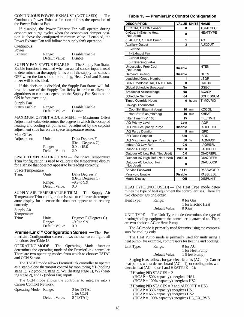
PremierLink™ Configuration Screen — The Pre-mierLink Configuration screen allows the user to configure allfunctions. See Table 13.OPERATING MODE — The Operating Mode functiondetermines the operating mode of the PremierLink controller.There are two operating modes from which to choose: TSTATand CCN Sensor.
The TSTAT mode allows PremierLink controller to operateas a stand-alone thermostat control by monitoring Y1 (coolingstage 1), Y2 (cooling stage 2), W1 (heating stage 1), W2 (heat-ing stage 2), and G (indoor fan) inputs.
The CCN mode allows the controller to integrate into aCarrier Comfort Network.Operating Mode: Range: 0 for TSTAT
1 for CCNDefault Value: 0 (TSTAT)
Table 13 — PremierLink Control Configuration
HEAT TYPE (NOT USED) — The Heat Type mode deter-mines the type of heat equipment the controller uses. There aretwo choices: gas or electric.Heat Type: Range: 0 for Gas
1 for Electric HeatDefault Value: 0 (Gas)
UNIT TYPE — The Unit Type mode determines the type ofheating/cooling equipment the controller is attached to. Thereare two choices: AC or Heat Pump.
The AC mode is primarily used for units using the compres-sors for cooling only.
The Heat Pump mode is primarily used for units using aheat pump (for example, compressors for heating and cooling).Unit Type: Range: 0 for AC
1 for Heat PumpDefault Value: 1 (Heat Pump)
Staging is as follows for gas electric units (AC = 0), Carrierheat pumps with a defrost board (AC = 1), or cooling units withelectric heat (AC = 0 or 1 and HEATYPE = 1):
If Heating PID STAGES = 2(HCAP = 50% capacity) energized HS1.(HCAP = 100% capacity) energizes HS2.
If Heating PID STAGES = 3 and AUXOUT = HS3(HCAP = 33% capacity) energizes HS1(HCAP = 66% capacity) energizes HS2(HCAP = 100% capacity) energizes H3_EX_RVS
DESCRIPTION VALUE UNITS NAME0=TSTAT, 1=CCN Sensor 0 TSTATCFG0=Gas, 1=Electric Heat(Not Used) 0 HEATTYPE
0=AC Unit, 1=Heat Pump 1 ACAuxiliary Output 3 AUXOUT
0=None1=Exhaust Fan2=Heat Stage3=Reversing Valve
Unoccupied Free Cool(Not Used) Disable NTEN
Demand Limiting Disable DLENLoadshed Group Number 1 LSGPCCN Broadcast OAT, ENTH,OAQ 0 OATBCGlobal Schedule Broadcast No GSBCBroadcast Acknowledge No BCACKSchedule Number 64 SCHEDNUMTimed Override Hours 0 hours TIMOVRIDLinkage Thermostat
Cool Strt Bias(min/deg) 10 min KCOOLHeat Strt Bias(min/deg) 10 min KHEAT
Filter Timer hrs* 100 15 FIL_TIMRIAQ Priority Level Low IAQPIAQ Pre-Occupancy Purge Disable IAQPURGEIAQ Purge Duration 5 min IQPDIAQ Delta Setpoint 650 IAQDIAQ Maximum Damper Pos. 50 % IAQMAXPIndoor AQ Low Ref. 0.0 IIAQREFLIndoor AQ High Ref. 2000.0 IIAQREFHOutdoor AQ Low Ref. (Not Used) 0.0 OIAQREFLOutdoor AQ High Ref. (Not Used) 2000.0 OIAQREFHOutdoor AQ Lockout Point(Not Used) 0 OIAQLOCK
Service Password 1111 PASSWORDPassword Enable Disable PASS_EBLMetric Display Off DISPUNIT
19
Staging occurs as follows for heat pump (AC = 1) units and(AUXOUT = 3) configured for reversing valve:
If Heating PID STAGES = 2(HCAP = 50% capacity) energizes CMP1 and CMP2,then 2 seconds later energizes H3_EX_RVS.(100% capacity) energizes HS1 and HS2.
If Heating PID STAGES = 3(33% capacity if) energizes CMP1 and CMP2, then2 seconds later energizes H3_EX_RVS.(66% capacity) energizes HS1(100% capacity) energizes HS2
AUXILIARY OUTPUT — The Auxiliary Output function isused to define the specific use of the Auxiliary Output on thecontroller board.
The output will be energized or deenergized by the appro-priate algorithm that uses that specific output.Auxiliary Output is displayed as one of the following:
0 = None 2 = Heat Stage1 = Exhaust Fan 3 = Reversing Valve
Auxiliary Output: Range: 0 to 3Default Value: 3
UNOCCUPIED FREE COOL (NOT USED) — The Unoc-cupied Free Cool function is used during unoccupied periods topre-cool the space using outside air when outside conditionsare suitable.Unoccupied Free Cool: Range: Disable/Enable
Default Value: Disable
DEMAND LIMITING — The Demand Limiting function isused to limit operating capacity of the unit to prevent systemoverloads. Both Heating and Cooling capacity is limited.
When the Demand Limit option is enabled, the control willrespond to the Loadshed Controller commands, such as Red-line Alert, Shed, Unshed, and Redline Cancel. If equipped withthe expansion I/O board, the control will also respond to theLoadshed Hardware input.DemandLimiting: Range: Disable/Enable
Default Value: DisableLOADSHED GROUP NUMBER — The Loadshed GroupNumber function defines the Loadshed table number (LDSH-DxxS, where xx is the configured loadshed group number) thatthe controller will respond to when a broadcast for Redline/Loadshed has been detected on the CCN bus. Unoccupied Free Cool: Range: 1 to 16
Default Value: 1
CCN, BROADCAST OAT, ENTHALPY, OAQ — Config-ures the controller to CCN broadcast any or all of the pointvalues for Outside Air Temperature (OAT), Enthalpy (ENTH),and Outdoor Air Quality (OAQ).Example: To broadcast OAQ and ENTH but not OAT, the cor-responding bitmap is 110; the binary equivalent of the decimalnumber 6. The configuration decision would then be set to a 6.CCN Broadcast, OAT, Enthalpy,OAQ Allowable Entries:
0 — None 5 — OAT and OAQ1 — OAT Only 6 — ENTH and OAQ2 — ENTH Only 7 — OAT, ENTH and OAQ3 — OAT and ENTH4 — OAQ OnlyDefault Value: 0 (disabled, no broadcasts performed)
GLOBAL SCHEDULE BROADCAST — The Global Sched-ule Broadcast setting configures the controller to broadcast orreceive a global schedule. If set to Yes, the controller will act asa global schedule master and its schedule will be broadcast tothe CCN. If set to No, the controller will not broadcast a globalschedule and it will receive the configured schedule number.Global ScheduleMaster: Range: No/Yes
Default Value: No
BROADCAST ACKNOWLEDGER — The Broadcast Ac-knowledger setting configures the controller to recognizebroadcast messages that appear on its CCN bus. NOTE: For proper CCN bus operation, there should be onlyone device per CCN bus that is configured as the BroadcastAcknowledger. Acknowledger: Range: No/Yes
Default Value: No
SCHEDULE NUMBER — The Schedule Number deter-mines which Global Occupancy Schedule that the controllerwill follow. A value of 64 disables global occupancy fromCCN and will decide Occupancy from its local schedule. Avalue between 65 and 99 will allow the controller to follow theglobal occupancy schedule of the number broadcast over CCN.Occupancy ScheduleNumber Range: 64 to 99
Default Value: 64
TIMED OVERRIDE HOURS — The Timed Override Hoursfunction is used to configure a timed override duration byentering the number of hours the override will be in effect.Pressing the override button on a space temperature sensor willcause an override.Timed OverrideHours: Range: 0 to 4
Default Value: 0
LINKAGE THERMOSTAT — The Linkage Thermostat starttime biases allow the installer to configure the time (per de-gree) the space should take to recover in the Heat and Coolmodes for optimum start with a Linkage Thermostat. Thesenumbers will be used to calculate the Start Bias time.Cool Start Bias: Units: Minutes/Degree
Range: 0 to 60Default Value: 10
Heat Start Bias Units: Minutes/DegreeRange: 0 to 60Default Value: 10
FILTER TIMER HOURS — The Filter Timer Hours config-uration determines when the filter status will display a “Dirty”alarm. When the Filter Timer Hours is configured to a valueother than zero and fan run time exceeds the value configured,the filter status will display “Dirty” and a CCN alarm will begenerated. Setting the configured Filter Timer Hours value tozero will disable the alarm condition. The value of the timer isstored in EEPROM to protect it in the event of a power failure.The value is stored every 24 hours.Filter Timer Hours: Range: 0 to 99
Default Value: 15 (where 15*100=1500)

20
INDOOR AIR QUALITY PRIORITY LEVEL — The IndoorAir Quality Priority Level, when set to Low, ensures that com-fort is not being compromised by bringing in too much outdoorair to maintain IAQ set point. When an override conditiontakes place, IAQ control is disabled, and Economizer Mini-mum Position is set to the user configured value MDP. Whenset to High, IAQ control is always active regardless of indoorcomfort conditions. The controller will temper cold air OAT<55 F to prevent cold blow.Indoor Air QualityPriority Level: Range: High/Low
Default Value: Low
INDOOR AIR QUALITY PREOCCUPANCY PURGE —The Indoor Air Quality Preoccupancy Purge brings in freshoutdoor air before the Occupied mode begins. The IAQ Pre-Occupancy Purge is used to lower carbon dioxide levels belowthe IAQ set point before Occupied mode starts.
The Purge is started two hours before the occupied time andlasts for the specified duration.Indoor Air QualityPreoccupancyPurge: Range: Disable/Enable
Default Value: DisableINDOOR AIR QUALITY PURGE DURATION — TheIndoor Air Quality Purge Duration specifies the duration ofIAQ Pre-Occupancy purge. The Purge is started two hoursbefore the occupied time and lasts for the specified duration.Indoor Air QualityPurge Duration: Display Units: Minutes
Display Range: 0 to 60Default Value: 5
INDOOR AIR QUALITY DELTA SET POINT — TheIndoor Air Quality Delta Set Point specifies the highestIndoor Air Quality level (measured in ppm) allowed within thespace whenever unit is in Occupied mode (or Supply Fan Onfor units with Thermostat control) and Indoor Air Qualitysensor is installed.Indoor Air QualityDelta Set Point: Display Units: PPM (parts per
million)Display Range: 1 to 5000Default Value: 650
INDOOR AIR QUALITY MAXIMUM DAMPER POSI-TION — This point displays the upper limit of the Indoor AirQuality minimum damper position calculated by the IAQcontrol.
For example, IAQ is calculating 100% Minimum DamperPosition, but this decision is set to 50%, IAQ Minimum Damp-er Position will be clamped to 50%.NOTE: When IAQ priority is set to HIGH, this value mustreflect the maximum outdoor air percent that the equipmentcan heat or cool at worst conditions.Indoor Air QualityMaximum DamperPosition: Display Units: % Open
Display Range: 0 to 100Default Value: 50
INDOOR AIR QUALITY SENSOR — The Indoor Air Qual-ity sensor defines the value in parts per million (ppm) whichcorrelates to the low and high voltage readings from the sensor.
Low Reference specifies the Low Point of the Indoor IAQSensor Range in ppm.Low Reference: Units: PPM (parts per million)
Range: 0 to 5000Default Value: 0
High Reference specifies the High Point of the Indoor IAQSensor Range in ppm.High Reference: Units: PPM (parts per million)
Range: 0 to 5000Default Value: 2000
OUTDOOR AIR QUALITY SENSOR (NOT USED) —The Outdoor Air Quality sensor defines the value in parts permillion (ppm) which correlates to the low and high voltagereadings from the sensor.
Low Reference specifies the Low Point of the Outdoor IAQSensor Range in ppm.Low Reference: Units: PPM (parts per million)
Range: 0 to 5000Default Value: 0
High Reference specifies the High Point of the OutdoorIAQ Sensor Range in ppm.High Reference: Units: PPM (parts per million)
Range: 0 to 5000Default Value: 2000
OUTDOOR AIR QUALITY LOCKOUT POINT (NOTUSED) — When set to non-zero value, the IAQ algorithmwill compare the Outdoor IAQ reading against this decisionand disable the IAQ control whenever the value of OAQexceeds this configured value.Outdoor Air Quality LockoutPoint: Range: 0 to 5000
Default Value: 0
SERVICE PASSWORD — The Service Password functiondefines the password needed to access the controller via theNavigator interface. Service Password: Range: 0000 to 9999
Default Value: 1111
PASSWORD ENABLE — The Password Enable function isused to require a password when attempting to access the con-troller via the Navigator interface. PasswordEnable: Range: Enable/Disable
Default Value: Disable
METRIC DISPLAY — The Metric Display function is usedto toggle the Navigator display between US and Metric units. Metric Display: Range: On/Off
Default Value: Off
Occupancy Maintenance Screen — The Occupan-cy Maintenance screen is used to check the occupied schedule.Information concerning the current occupied period is dis-played. See Table 14.
Table 14 — Occupancy Maintenance
DESCRIPTION VALUE UNITS NAMEMode 0 MODECurrent Occupied Period 0 PERIODOverride in Progress No OVERLASTOverride Duration 0 min OVERDURAOccupied Start Time 00:00 OCCSTARTUnoccupied Start Time 00:00 UNSTARTNext Occupied Day NXTOCCDNext Occupied Time 00:00 NXTOCCTNext Unoccupied Day NXTUNODNext Unoccupied Time 00:00 NXTUNOTLast Unoccupied Day PRVUNODLast Unoccupied Time 00:00 PRVUNOT

21
MODE — The Mode point displays the current occupiedmode for the controller. If the controller is following its ownlocal schedule this is the result of the local schedule status. Ifthe controller is configured to follow a global schedule, thispoint displays the mode last received from a global schedulebroadcast. Mode: Display Range: 0 to 1
Default Value: 0Network Access: None
CURRENT OCCUPIED PERIOD — If the controller is con-figured to determine occupancy locally, the Current OccupiedPeriod point is used to display the current period determiningoccupancy.Current OccupiedPeriod: Display Range: 1 to 8
Default Value: 0Network Access: None
OVERRIDE IN PROGRESS — The Override in Progresspoint is used to display if an occupancy override is in progress.The point will display “Yes” if an override is in progress, or“No” if there is no override.Override InProgress: Display Range: Yes/No
Default Value: NoNetwork Access: None
OVERRIDE DURATION — The Override Duration pointdisplays the number of minutes remaining for an occupancyoverride that is in effect. If the override duration value down-loaded is in hours, the value will be converted to minutes. If theoccupancy schedule is occupied when override is initiated, thecurrent occupancy period will be extended by the number ofhours/minutes requested.
If the current occupancy period is unoccupied when the oc-cupancy override is initiated, the mode will change to occupiedfor the duration of hours/minutes downloaded. If the occupan-cy override is due to end after the start of the next occupancyperiod, the mode will transition from occupancy override to oc-cupied without becoming unoccupied, and the occupancy over-ride timer will be reset.OverrideDuration: Display Units: Minutes
Display Range: 0 to 240Default Value: 0Network Access: None
OCCUPIED START TIME — The Occupied Start Timepoint shows the time that the current occupied mode began. Ifthe current mode is unoccupied or the controller is following aglobal schedule, the value displayed by this point will remain atdefault.OccupiedStart Time: Display Range: 00:00 to 24:00
Default Value: 00:00Network Access: None
UNOCCUPIED START TIME — The Unoccupied Start Timepoint shows the time that the current occupied mode will end.This will also be the beginning of the next unoccupied mode. Ifthe current mode is unoccupied or the controller is following aglobal schedule, the value displayed by this point will remain atdefault.UnoccupiedStart Time: Display Range: 00:00 to 24:00
Default Value: 00:00Network Access: None
NEXT OCCUPIED DAY — The Next Occupied Day pointdisplays the day of the week when the next occupied periodwill begin. This point is used with the Next Occupied Time sothe user will know when the next occupied period will occur. Ifthe controller is following a global schedule this point willremain at default.Next OccupiedDay: Display Range: MON, TUE, WED,
THU, FRI, SAT, SUNDefault Value: No display (Blank)Network Access: None
NEXT OCCUPIED TIME — The Next Occupied Time pointdisplays the time of day when the next occupied period willbegin. This point is used with the Next Occupied Day so theuser will know when the next occupied period will occur. If thePremierLink™ controller is following a global schedule thispoint will remain at default.Next OccupiedTime: Display Range: 00:00 to 24:00
Default Value: 00:00Network Access: None
NEXT UNOCCUPIED DAY — The Next Unoccupied Daypoint displays the day of the week when the next unoccupiedperiod will begin. This point is used with the Next UnoccupiedTime so the user will know when the next unoccupied periodwill occur. If the controller is following a global schedule thispoint will remain at default. Next UnoccupiedDay: Display Range: MON, TUE, WED,
THU, FRI, SAT, SUNDefault Value: No display (Blank)Network Access: None
NEXT UNOCCUPIED TIME — The Next Unoccupied Timepoint displays the time of day when the next unoccupiedperiod will begin. This point is used with the Next UnoccupiedDay so the user will know when the next unoccupied periodwill occur. If the controller is following a global schedule thispoint will remain at default.Next UnoccupiedTime: Display Range: 00:00 to 24:00
Default Value: 00:00Network Access: None
LAST UNOCCUPIED DAY — The Last Unoccupied Daypoint displays the day of the week when the controller lastchanged from occupied to the Unoccupied mode. This point isused in conjunction with the Last Unoccupied Time to knowthe last time and day when the controller became unoccupied.If the controller is following a global schedule this point willremain at default.Last UnoccupiedDay: Display Range: MON, TUE, WED,
THU, FRI, SAT, SUNDefault Value: No display (Blank)Network Access: None
LAST UNOCCUPIED TIME — The Last Unoccupied Timepoint displays the time of day when the controller last changedfrom occupied to the Unoccupied mode. This point is read inconjunction with the Last Unoccupied Day to know the lasttime and day when the controller became unoccupied. If thecontroller is following a global schedule this point will remainat default.Last UnoccupiedTime Display Range: 00:00 to 24:00
Default Value: 00:00Network Access: None

22
Maintenance Screen — The Maintenance Screen isused to service the PremierLink™ controller. See Table 15.THERMOSTAT CONTROL — Indicates the result of theconfiguration decision to control in the thermostat or sensormode.ThermostatControl: Display Range: No/Yes
Default Value: Yes Network Access: Read Only
OCCUPIED — The Occupied point indicates whether or notthe controller is operating in the Occupied mode.Occupied: Display Range: No/Yes
Default Value: NoNetwork Access: Read/Write
TIMED OVERRIDE IN EFFECT — The Timed Override InEffect point shows if a timed override is currently in effect.Timed Overridein Effect: Display Range: No/Yes
Default Value: NoNetwork Access: Read Only
START BIAS TIME — The Start Bias Time, in minutes, iscalculated by the controller during the unoccupied period (asneeded) to bring the temperature up or down to the set pointunder the optimum start routine. The start time bias for heatand cool are configurable. This value will be reported to theLinkage Thermostat if it is used. It cannot be used with GlobalScheduling.Start Bias Time: Display Units: Minutes
Display Range: 0 to 180Default Value: 0Network Access: Read Only
HEAT — The Heat point shows if there is a demand for heat inthe space. The space temperature must be below the OccupiedLow or Unoccupied Low set point.NOTE: When a control mode ends, “NO” mode must be com-pleted before opposite mode can begin.Heat: Display Range: No/Yes
Default Value: NoNetwork Access: None
COOL — The Cool point shows if there is a demand for cool-ing in the space. The space temperature must be above theOccupied High or Unoccupied High set point.NOTE: When a control mode ends, “NO” mode must be com-pleted before opposite mode can begin.Cool: Display Range: No/Yes
Default Value: NoNetwork Access: None
IAQ CONTROL — Indicates weather or not IAQ control isactive in the controller. IAQ control of the minimum damperposition is active whenever the configured parameters for theIAQ PID calculate a minimum position greater than the config-ured economizer minimum position. IAQ Control: Display Range: No/Yes
Default Value: No Network Access: Read Only
DEMAND LIMIT — Indicates that a command has beenreceived to limit capacity or reduce capacity of the heating orcooling.Demand Limit: Display Range: No/Yes
Default Value: No Network Access: Read Only
TEMP COMPENSATED START — Indicates that the con-troller has started the equipment prior to occupancy in order tobe at the occupied set points at the start of occupancy.TempCompensatedStart: Display Range: No/Yes
Default Value: No Network Access: Read Only
IAQ PRE-OCCUPANCY PURGE — Indicates that the pre-occupancy purge mode is currently active.IAQPre-occupancyPurge: Display Range: No/Yes
Default Value: No Network Access: Read Only
UNOCCUPIED FREE COOLING — Indicates that unoccu-pied free cooling is in effect.Unoccupied FreeCooling: Display Range: No/Yes
Default Value: No Network Access: Read Only
FIRE SHUTDOWN — Indicates (in a sensor mode) that theFire shutdown input has been sensed. This will also cause thesupply fan and heating and cooling to be turned off.Fire Shutdown: Display Range: No/Yes
Default Value: No Network Access: Read/Write
LINKAGE CONTROL — Indicates if the controller is receiv-ing linkage communication.Linkage Control: Display Range: No/Yes
Default Value: No Network Access: Read/Write
FIELD/STARTUP TEST — This point is used to enable acontroller field test. When forced to Yes, the controller will per-form a test of all outputs and reset to “NO” at end of test. Thetest may be aborted at any time by forcing value to NO.Field/StartupTest: Display Range: No/Yes
Default Value: No Network Access: Read/Write
HEAT SUBMASTER REFERENCE — When in sensormode, the Heat Submaster Reference point displays the supplyair temperature calculated by the heating PID loop. This valueis compared to the actual supply air temperature to determinethe number of required stages. When in the thermostat mode,the value displayed is zero.Heat SubmasterReference: Display Units: Degrees F (Degrees C)
Display Range: 40.0 to 150.0Default Value: 40Network Access: Read Only
COOL SUBMASTER REFERENCE — The Cool Submas-ter Reference point displays the supply air temperature calcu-lated by the cooling PID loop when in sensor mode. This valueis compared to the actual supply air temperature to determinethe number of required stages. When in the thermostat mode,the value displayed is zero.Cool SubmasterReference: Display Units: Degrees F (Degrees C)
Display Range: 40.0 to 150.0Default Value: 150Network Access: Read Only

23
ECONOMIZER SUBMASTER REFERENCE (NOTUSED) — This point displays the supply air temperature deter-mined by the Economizer PID calculation. EconomizerSubmasterReference: Display Units: Degrees F (Degrees C)
Display Range: 48 to 120Default Value: 120Network Access: Read Only
ECONOMIZER SUBMASTER GAIN (NOT USED) —Displays the current Submaster gain multiplier in use to calcu-late the economizer damper position. At temperatures below45 F this number will decrease to slow the rate of movement ofthe economizer damper.EconomizerSubmaster Gain: Display Range: –20 to 20
Default Value: –5.5Network Access: Read Only
COMPRESSOR STARTS — Displays the total number ofcompressor starts.CompressorStarts: Default Value: 0
Network Access: Read Only
COMPRESSOR 1 RUN TIME — Displays the number ofrun hours of compressor no. 1.Compressor 1Run Time: Display Units: Hours
Default Value: 0Network Access: Read Only
COMPRESSOR 2 RUN TIME — Displays the number ofrun hours of compressor 2.Compressor 2Run Time: Display Units: Hours
Default Value: 0Network Access: Read Only
SUPPLY FAN RUN TIME — Displays the number of supplyfan run hours. This is not the same timer used for the filter sta-tus. A separate timer is used to keep track of the run hours sincethe last filter change.Supply FanRun Time: Display Units: Hours
Default Value: 0Network Access: Read Only
LINKAGE THERMOSTAT — The following Linkage Ther-mostat points display the standard values received from aLinkage Thermostat (if one is being used to provide spacetemperature, set point and occupancy information).LinkageStatus: Display Range: 0 to 3
Default Value: 2Network Access: None
The Supervisory Element displays the address of the devicesending the linkage supervisory table to the PremierLink™controller.Supervisory Element: Default Value: 0
Network Access: Read OnlyThe Supervisory Bus displays the bus number of the device
sending the linkage supervisory table to the PremierLinkcontroller.Supervisory Bus: Default Value: 0
Network Access: Read Only
The Supervisory Block displays the block or tablenumber of the linkage table occurrence in the supervisorydevice. Some linkage supervisory devices may containmore than one linkage table for different air sources. Supervisory Block: Default Value: 0
Network Access: Read OnlyThe Average Occupied Heat Set Point displays the
Occupied Heat set point from the Linkage Thermostat.Average OccupiedHeat Set Point: Display Units: Degrees F (Degrees C)
Display Range: 0.0 to 99.9Default Value: 0.0Network Access: None
The Average Occupied Cool Set Point displays the Occu-pied Cool set point from the Linkage Thermostat.Average OccupiedCool Set Point: Display Units: Degrees F (Degrees C)
Display Range: 0.0 to 99.9Default Value: 0.0Network Access: None
The Average Unoccupied Heat Set Point displays the Unoc-cupied heat set point from the Linkage Thermostat.Average UnoccupiedHeat Set Point: Display Units: Degrees F (Degrees C)
Display Range: 0.0 to 99.9Default Value: 0.0Network Access: None
The Average Unoccupied Cool Set Point displays the Unoc-cupied cool set point from the Linkage Thermostat.Average UnoccupiedCool Set Point: Display Units: Degrees F (Degrees C)
Display Range: 0.0 to 99.9Default Value: 0.0Network Access: None
The Average Zone Temperature displays the space tempera-ture from the Linkage Thermostat.Average ZoneTemperature: Display Units: Degrees F (Degrees C)
Display Range: 0.0 to 99.9Default Value: 0.0Network Access: None
The Average Occupied Zone Temperature displays thespace temperature from the Linkage Thermostat during occu-pied periods.Average OccupiedZone Temperature: Display Units: Degrees F (Degrees C)
Display Range: 0.0 to 99.9Default Value: 0.0Network Access: None
The Occupancy Status point displays a 1 if occupancy is re-ported by the Linkage Thermostat. The Occupancy Statuspoint displays a 0 if occupancy is not reported by the LinkageThermostat.OccupancyStatus: Display Range: 0, 1
Default Value: 0Network Access: None

Manufacturer reserves the right to discontinue, or change at any time, specifications or designs without notice and without incurring obligations.PC 111 Catalog No. 535-00091 Printed in U.S.A. Form 50-9SI Pg 24 11-02 Replaces: NewBook 1 4
Tab 5a 5a
Copyright 2002 Carrier Corporation
Table 15 — Maintenance
NOTE: Bold values indicate points that can be forced through communications.
DESCRIPTION VALUE UNITS STATUS FORCE NAMEThermostat Control No TSTATOccupied Yes OCCUPTimed Override in Effect No TIMOVStart Bias Time 0 min STRTBIASHeat No HEATCool No COOLIAQ Control No IAQCLDemand Limit No DEMLTTemp Compensated Start No TCSTRIAQ Pre-Occupancy Purge No IQPRGUnoccupied Free Cool No NTFCLFire Shutdown No FIRESLinkage Control No DAVCLField/Startup Test No FIELDHeat Submaster Ref 40.0 dF SHSRCool Submaster Ref 150.0 dF CCSREconomizer Submaster Ref 120.0 dF ECONSREconomizer Submastr Gain 0.00 ECONGNCompressor Starts 0.00 CMPSTCompressor 1 Runtime 0.00 HOURS CM1RTCompressor 2 Runtime 0.00 HOURS CM2RTSupply Fan Runtime 17.00 HOURS FANRTLinkage Thermostat
Linkage Status 2 LINKSTATSupervisory Element 0 SUPE-ADRSupervisory Bus 0 SUPE-BUSSupervisory Block 0 BLOCKNUM
Average Occ Heat Setpt 0.0 dF OCLOSTPTAverage Occ Cool Setpt 0.0 dF OCHISTPTAverage Unoc Heat Setpt 0.0 dF UNLOSTPTAverage Unoc Cool Setpt 0.0 dF UNHISTPTAverage Zone Temp 0.0 dF AZTAverage Occ Zone Temp 0.0 dF AOZTOccupancy Status (1=occ) 1 OCCSTAT