Embed Size (px)
Citation preview
GENERAL
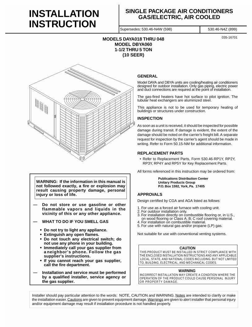
Model DAYA and DBYA units are cooling/heating air conditionersdesigned for outdoor installation. Only gas piping, electric powerand duct connections are required at the point of installation.
The gas-fired heaters have hot surface to pilot ignition. Thetubular heat exchangers are aluminized steel.
This appliance is not to be used for temporary heating ofbuildings or structures under construction.
INSPECTION
As soon as a unit is received, it should be inspected for possibledamage during transit. If damage is evident, the extent of thedamage should be noted on the carrier’s freight bill. A separaterequest for inspection by the carrier’s agent should be made inwriting. Refer to Form 50.15-NM for additional information.
REPLACEMENT PARTS• Refer to Replacement Parts, Form 530.46-RP1Y, RP2Y,
RP3Y, RP4Y and RP5Y for Key Replacement Parts.
All forms referenced in this instruction may be ordered from:
Publications Distribution CenterUnitary Products GroupP.O. Box 1592, York, Pa. 17405
APPROVALS
Design certified by CGA and AGA listed as follows:
1. For use as a forced air furnace with cooling unit.2. For outdoor installation only.3. For installation directly on combustible flooring or, in U.S., on wood flooring or Class A; B; C roof covering material.4. For installation on combustible material.5. For use with natural gas and/or propane (LP) gas.
Not suitable for use with conventional venting systems.
Installer should pay particular attention to the words: NOTE, CAUTION and WARNING. Notes are intended to clarify or makethe installation easier. Cautions are given to prevent equipment damage. Warnings are given to alert installer that personal injuryand/or equipment damage may result if installation procedure is not handled properly.
CAUTION
THE ENCLOSED INSTALLATION INSTRUCTIONS AND ANY APPLICABLELOCAL, STATE, AND NATIONAL CODES INCLUDING, BUT NOT LIMITEDTO, BUILDING, ELECTRICAL, AND MECHANICAL CODES.
THIS PRODUCT MUST BE INSTALLED IN STRICT COMPLIANCE WITH
WARNING
OPERATION OF THE PRODUCT COULD CAUSE PERSONAL INJURYO R PRO PERTY DAM AG E.
INCORRECT INSTALLATION MAY CREATE A CONDITION WHERE THE
— Do not store or use gasoline or otherflammable vapors and liquids in thevicinity of this or any other appliance.
— WHAT TO DO IF YOU SMELL GAS
• Do not try to light any appliance.• Extinguish any open flames.• Do not touch any electrical switch; do
not use any phone in your building.• Immediately call your gas supplier from
a neighbor’s phone. Follow the gassupplier’s instructions.
• If you cannot reach your gas supplier,call the fire department.
— Installation and service must be performedby a qualified installer, service agency orthe gas supplier.
WARNING: If the information in this manual isnot followed exactly, a fire or explosion mayresult causing property damage, personalinjury or loss of life.
035-16701
INSTALLATIONINSTRUCTION
SINGLE PACKAGE AIR CONDITIONERSGAS/ELECTRIC, AIR COOLED
Supersedes: 530.46-N4W (598) 530.46-N4Z (899)
MODELS DAYA018 THRU 048MODEL DBYA0601-1/2 THRU 5 TON
(10 SEER)
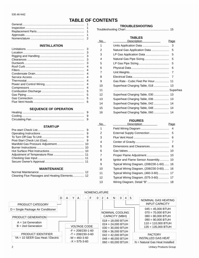
TABLE OF CONTENTSGeneral ............................................................................. 1Inspection ......................................................................... 1Replacement Parts ........................................................... 1Approvals.......................................................................... 1Nomenclature ................................................................... 2
INSTALLATIONLimitations ........................................................................ 3Location ............................................................................ 3Rigging and Handling ....................................................... 3Clearances ....................................................................... 3Ductwork........................................................................... 3Roof Curb ......................................................................... 4Filters ................................................................................ 4Condensate Drain............................................................. 4Service Access................................................................. 4Thermostat ....................................................................... 4Power and Control Wiring................................................. 4Compressors .................................................................... 4Combustion Discharge ..................................................... 5Gas Piping ........................................................................ 5Gas Connection................................................................ 5Flue Vent Hoods ............................................................... 6
SEQUENCE OF OPERATIONHeating ............................................................................. 9Cooling.............................................................................. 9Circulating Fan.................................................................. 9
START-UPPre-start Check List.......................................................... 9Operating Instructions ...................................................... 9To Turn Off Gas To Unit..................................................... 9Post-Start Check List (Gas).............................................. 9Manifold Gas Pressure Adjustment.................................. 10Burner Instructions ........................................................... 10Hot Surface Pilot Instructions ........................................... 10Adjustment of Temperature Rise ...................................... 11Checking Gas Input .......................................................... 11Secure Owner’s Approval ................................................. 11
MAINTENANCENormal Maintenance ........................................................ 12Cleaning Flue Passages and Heating Elements.............. 12
D A Y A - F 02 5N
NOMENCLATURE
PRODUCT GENERATION
A = 1st GenerationB = 2ed Generation
PRODUCT CATEGORY
D = Single Package Air Conditioner
PRODUCT IDENTIFIERYA = 10 SEER Gas Heat / Electric
VOLTAGE CODE
-F = 208/230-1-60-T = 208/230-3-60-W = 460-3-60 -X = 575-3-60
NOMINAL COOLINGCAPACITY (MBH)
018 = 18,000 BTUH024 = 24,000 BTUH030 = 30,000 BTUH036 = 36,000 BTUH042 = 42,000 BTUH048 = 48,000 BTUH060 = 60,000 BTUH
FACTORYINSTALLED GAS HEAT
N = Natural Gas Heat Installed
0 44NOMINAL GAS HEATING
INPUT CAPACITY
045 = 45,000 BTUH070 = 70,000 BTUH080 = 80,000 BTUH090 = 90,000 BTUH
110 = 110,000 BTUH135 = 135,000 BTUH
TROUBLESHOOTINGTroubleshooting Chart ...................................................... 15
TABLES No. Description Page
1 Units Application Data ................................. 3
2 Natural Gas Application Data ...................... 5
3 LP Gas Application Data ............................. 5
4 Natural Gas Pipe Sizing............................... 5
5 LP Gas Pipe Sizing...................................... 5
6 Physical Data ............................................... 6
7 Unit Weights................................................. 7
8 Electrical Data.............................................. 7
9 Gas Rate - Cubic Feet Per Hour.................. 11
10 Superheat Charging Table, 018 ................... 13
11 ..................................................................... Superhea
12 Superheat Charging Table, 030 ................... 13
13 Superheat Charging Table, 036 ................... 13
14 Superheat Charging Table, 042 ................... 14
15 Superheat Charging Table, 048 ................... 14
16 Superheat Charging Table, 060 ................... 14
FIGURES No. Description Page
1 Field Wiring Diagram ................................... 4
2 External Supply Connection ........................ 5
3 Flue Vent Hood ............................................ 6
4 Center of Gravity.......................................... 7
5 Dimensions and Clearances........................ 8
6 Gas Valves ................................................... 10
7 Proper Flame Adjustment............................ 10
8 Ignitor and Flame Sensor Assembly............ 10
9 Typical Wiring Diagram, (208/230-1-60) ...... 16
10 Typical Wiring Diagram, (208/230-3-60) ...... 16
11 Typical Wiring Diagram, (460-3-60) ............. 17
12 Typical Wiring Diagram, (575-3-60) ............. 17
13 Wiring Diagram, Detail “B” ........................... 18
530.46-N4Z
2 Unitary Products Group
LIMITATIONS
These units must be installed in accordance with the followingnational and local safety codes.
1. National Electrical Code ANSI/NFPS No. 70 or CanadianElectrical Code Part 1, C22.1 (latest editions).
2. National Fuel Gas Code Z223.1 or CAN/CGA B149.1 or .2Installation Code.
3. Local gas utility requirements.
4. Local plumbing and waste water codes and other applica-ble local codes.
Refer to Table 1 for unit application data and to Table 2 for gasheat application data.
If components are to be added to a unit to meet local codes, theyare to be installed at the dealer’s and/or the customer’s expense.
Size of unit for proposed installation should be based on heatloss/heat gain calculations made in accordance with industryrecognized procedures identified by the Air Conditioning Con-tractors of America.
LOCATION
Use the following guidelines to select a suitable location forthese units.
1. Unit is designed for outdoor installation only.
2. Condenser must have an unlimited supply of air. Where achoice of location is possible, position unit on either northor east side of building.
WARNING: Excessive exposure of this furnace to contami-nated combustion air may result equipment dam-age or personal injury. Typical contaminatesinclude: permanent wave solutions, chlorinatedwaxes and cleaners, chlorine based swimmingpool chemicals, water softening chemicals, carbontetrachloride, Halogen type refrigerants, cleaningsolvents (e.g. perchloroethylene), printing inks,paint removers, varnishes, hydrochloric acid, ce-ments and glues, antistatic fabric softeners forclothes dryers, masonry acid washing materials.
3. For ground level installation, a level pad or slab should beused. The thickness and size of the pad or slab used shouldmeet local codes and unit weight. Do not tie the slab to thebuilding foundation.
4. For roof top installation, be sure the structure will supportthe weight of the unit plus any field installed components.Unit must be installed on a level roof curb or appropriateangle iron frame providing adequate support under thecompressor/condenser section.
5. Maintain level tolerance of unit to 1/8" maximum.
RIGGING OR HANDLING
Care must be exercised when moving the unit. Do not removeany packaging until the unit is near the place of installation. Rigunit with slings placed under the unit. Spreader bars of sufficientlength should be used across the top of the unit.
BEFORE LIFTING A UNIT, MAKE SURE THAT ITS WEIGHTIS DISTRIBUTED EQUALLY ON THE CABLES SO THAT ITWILL LIFT EVENLY.
Units may also be moved or lifted with a fork-lift. Slottedopenings in the skid are provided for this purpose. Forks mustpass completely through the base.
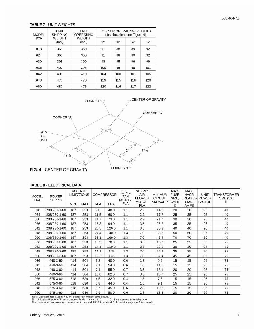
Refer to Table 7 for unit weights and to Figure 4 for approximatecenter of gravity.
CLEARANCES
All units require certain clearances for proper operation andservice. Refer to Figure 5 for the clearances required forcombustion, construction, servicing and proper unit operation.
WARNING: Do not permit overhanging structures or shrubs toobstruct the condenser air discharge, combustionair inlet or vent outlet.
DUCT WORK
These units are adaptable to downflow use as well as rearsupply and return air duct openings. To convert to downflow,use the following steps:
1. Remove the duct covers found in the bottom return andsupply air duct openings. There are four (4) screws securingeach duct cover (save these screws to use later).
2. Install the duct covers, removed in step one, to the rearsupply and return air duct openings. Secure with the four(4) screws used in step one.
3. Seal the duct covers with silicone caulk.
Duct work should be designed and sized according to themethods of the Air Conditioning Contractors of America(ACCA), as set forth in their Manual D.
A closed return duct system shall be used. This shall notpreclude use of economizers or ventilation air intake. Flexiblejoints may be used in the supply and return duct work tominimize the transmission of noise.
CAUTION: When fastening duct work to the side duct flanges onthe unit, insert the screws through the duct flanges only.DO NOT insert the screws through the casing. Outdoorduct work must be insulated and waterproofed.
NOTE: Be sure to note supply and return openings.
Refer to Figure 5 for information concerning rear and bottomsupply and return air duct openings.
INSTALLATION
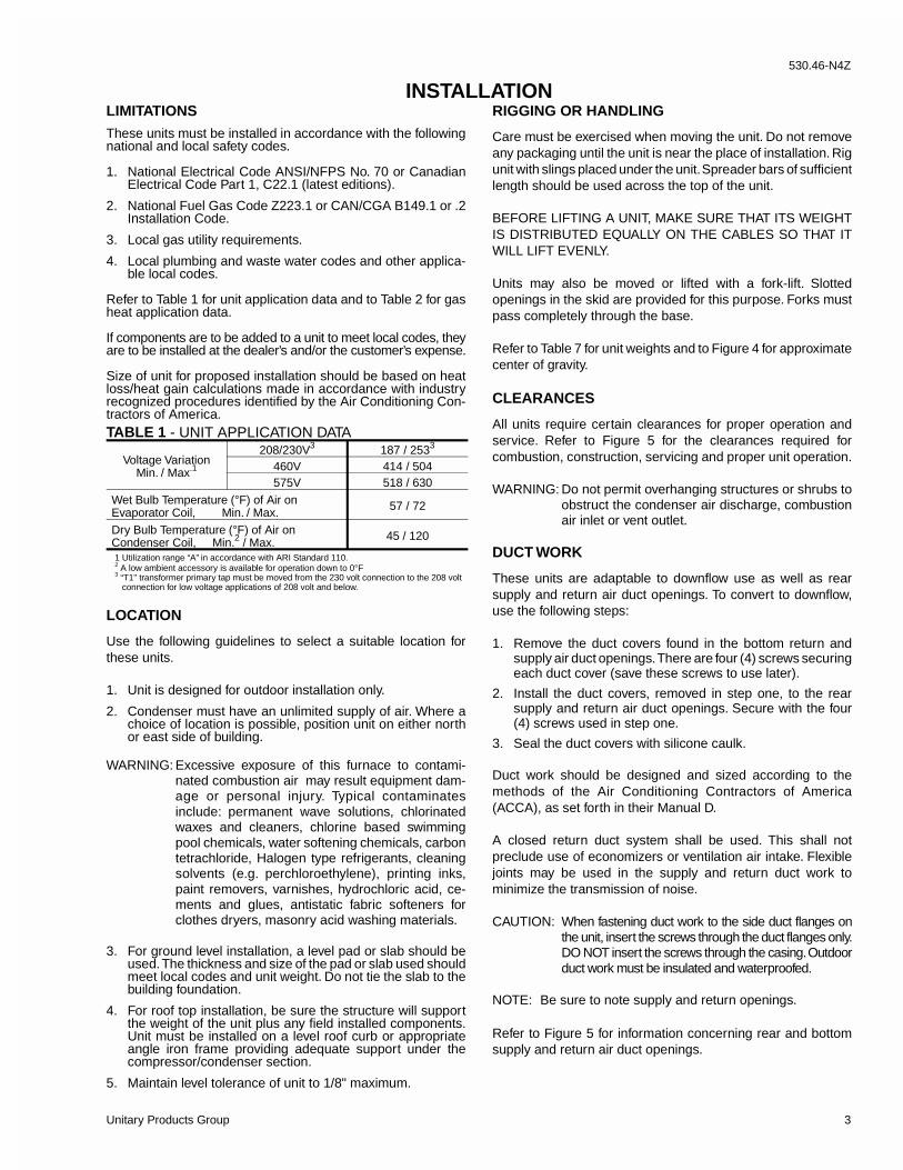
Voltage VariationMin. / Max.1
208/230V3 187 / 2533
460V 414 / 504575V 518 / 630
Wet Bulb Temperature (°F) of Air onEvaporator Coil, Min. / Max. 57 / 72
Dry Bulb Temperature (°F) of Air onCondenser Coil, Min.2 / Max. 45 / 120
1 Utilization range “A” in accordance with ARI Standard 110.2 A low ambient accessory is available for operation down to 0°F3 “T1" transformer primary tap must be moved from the 230 volt connection to the 208 volt connection for low voltage applications of 208 volt and below.
TABLE 1 - UNIT APPLICATION DATA
530.46-N4Z
Unitary Products Group 3
ROOF CURB
On applications when a roof curb is used, the unit must bepositioned on the curb so the front of the unit is tight againstthe curb.
FILTERS
Single phase units are shipped without a filter and is the respon-sibility of the installer to secure a filter in the return air ductworkor install a Filter/Frame Kit (1FF0110 for the DAYA018 thruDAYA042 and 1FF0112 for the DAYA048 and DBYA060).
A filter rack and filters are standard on three phase units.
NOTE: Filters on the DAYA048 and DBYA060 units require theuse of a 5⁄16" nut driver for removal.
Filters must always be used and must be kept clean. Whenfilters become dirt laden, insufficient air will be delivered by theblower, decreasing your units efficiency and increasing operat-ing costs and wear-and-tear on the unit and controls.
Filters should be checked monthly especially since this unit isused for both heating and cooling.
CONDENSATE DRAIN
A condensate trap is recommended to be installed in thecondensate drain. The plumbing must conform to local codes.Use a sealing compound on male pipe threads. Install thecondensate drain line (3⁄4“ NPTF) to spill into an open drain.
SERVICE ACCESS
Access to all serviceable components is provided by the follow-ing removable panels:
• Blower compartment• Gas control/electrical service access
Refer to Figure 5 for location of these access panels andminimum clearances.
THERMOSTAT
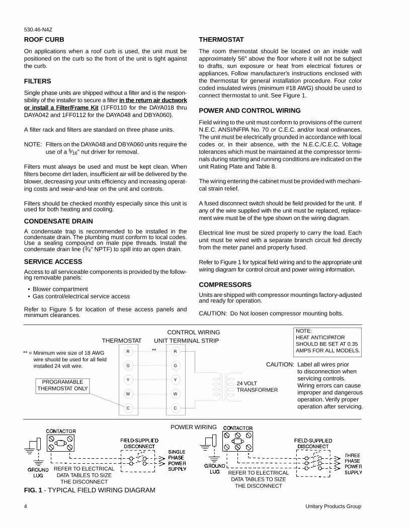
The room thermostat should be located on an inside wallapproximately 56" above the floor where it will not be subjectto drafts, sun exposure or heat from electrical fixtures orappliances. Follow manufacturer’s instructions enclosed withthe thermostat for general installation procedure. Four colorcoded insulated wires (minimum #18 AWG) should be used toconnect thermostat to unit. See Figure 1.
POWER AND CONTROL WIRING
Field wiring to the unit must conform to provisions of the currentN.E.C. ANSI/NFPA No. 70 or C.E.C. and/or local ordinances.The unit must be electrically grounded in accordance with localcodes or, in their absence, with the N.E.C./C.E.C. Voltagetolerances which must be maintained at the compressor termi-nals during starting and running conditions are indicated on theunit Rating Plate and Table 8.
The wiring entering the cabinet must be provided with mechani-cal strain relief.
A fused disconnect switch should be field provided for the unit. Ifany of the wire supplied with the unit must be replaced, replace-ment wire must be of the type shown on the wiring diagram.
Electrical line must be sized properly to carry the load. Eachunit must be wired with a separate branch circuit fed directlyfrom the meter panel and properly fused.
Refer to Figure 1 for typical field wiring and to the appropriate unitwiring diagram for control circuit and power wiring information.
COMPRESSORS
Units are shipped with compressor mountings factory-adjustedand ready for operation.
CAUTION: Do Not loosen compressor mounting bolts.
�
�
�
�
�
�
��
�
�
24 VOLTTRANSFORMER
UNIT TERMINAL STRIPTHERMOSTAT
NOTE:HEAT ANTICIPATORSHOULD BE SET AT 0.35AMPS FOR ALL MODELS.
CAUTION: Label all wires priorto disconnection whenservicing controls.Wiring errors can causeimproper and dangerousoperation. Verify properoperation after servicing.
PROGRAMABLETHERMOSTAT ONLY
CONTROL WIRING
** = Minimum wire size of 18 AWG wire shuold be used for all field installed 24 volt wire.
**
REFER TO ELECTRICALDATA TABLES TO SIZE
THE DISCONNECT
REFER TO ELECTRICALDATA TABLES TO SIZE
THE DISCONNECT
POWER WIRING
FIG. 1 - TYPICAL FIELD WIRING DIAGRAM
530.46-N4Z
4 Unitary Products Group
Scroll compressors operate in one direction only. If a threephase scroll compressor is experiencing:
• Low amperage draw• Similar discharge and suction pressures• Increased noise level
then the compressor is operating in reverse. To correct thiscondition, switch any two (2) line voltage leads at the contactor.Please note, single phase scroll compressor will start and runin one direction only. The reverse operation is not a concern.
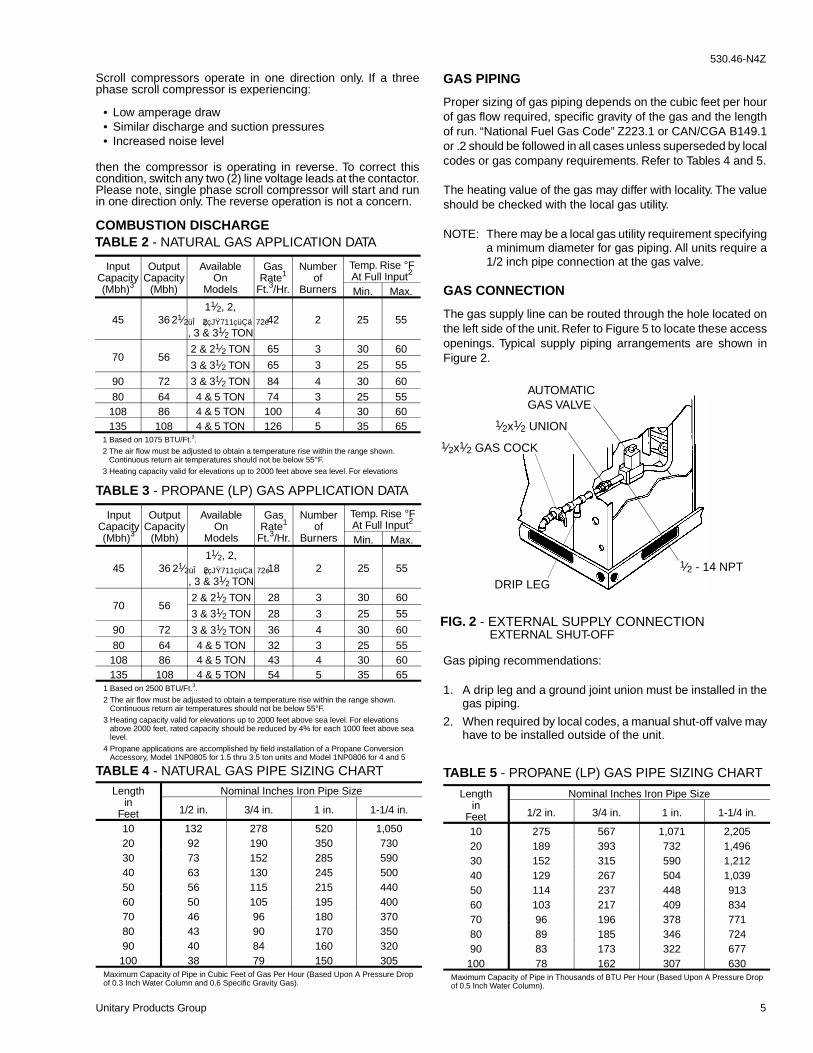
COMBUSTION DISCHARGE
GAS PIPING
Proper sizing of gas piping depends on the cubic feet per hourof gas flow required, specific gravity of the gas and the lengthof run. “National Fuel Gas Code” Z223.1 or CAN/CGA B149.1or .2 should be followed in all cases unless superseded by localcodes or gas company requirements. Refer to Tables 4 and 5.
The heating value of the gas may differ with locality. The valueshould be checked with the local gas utility.
NOTE: There may be a local gas utility requirement specifyinga minimum diameter for gas piping. All units require a1/2 inch pipe connection at the gas valve.
GAS CONNECTION
The gas supply line can be routed through the hole located onthe left side of the unit. Refer to Figure 5 to locate these accessopenings. Typical supply piping arrangements are shown inFigure 2.
Gas piping recommendations:
1. A drip leg and a ground joint union must be installed in thegas piping.
2. When required by local codes, a manual shut-off valve mayhave to be installed outside of the unit.
FIG. 2 - EXTERNAL SUPPLY CONNECTIONEXTERNAL SHUT-OFF
1⁄2x1⁄2 UNION
1⁄2x1⁄2 GAS COCK
AUTOMATICGAS VALVE
1⁄2 - 14 NPT
DRIP LEG
InputCapacity(Mbh)3
OutputCapacity
(Mbh)
AvailableOn
Models
GasRate1
Ft.3/Hr.
Numberof
Burners
Temp. Rise °FAt Full Input2
Min. Max.
45 3611⁄2, 2,
21⁄2üÎ ç2çJŸ711çüÇä 72é
, 3 & 31⁄2 TON42 2 25 55
70 562 & 21⁄2 TON 65 3 30 60
3 & 31⁄2 TON 65 3 25 55
90 72 3 & 31⁄2 TON 84 4 30 60
80 64 4 & 5 TON 74 3 25 55108 86 4 & 5 TON 100 4 30 60135 108 4 & 5 TON 126 5 35 65
1 Based on 1075 BTU/Ft.3.2 The air flow must be adjusted to obtain a temperature rise within the range shown. Continuous return air temperatures should not be below 55°F.3 Heating capacity valid for elevations up to 2000 feet above sea level. For elevations
TABLE 2 - NATURAL GAS APPLICATION DATA
InputCapacity(Mbh)3
OutputCapacity
(Mbh)
AvailableOn
Models
GasRate1
Ft.3/Hr.
Numberof
Burners
Temp. Rise °FAt Full Input2
Min. Max.
45 3611⁄2, 2,
21⁄2üÎ ç2çJŸ711çüÇä 72é
, 3 & 31⁄2 TON18 2 25 55
70 562 & 21⁄2 TON 28 3 30 60
3 & 31⁄2 TON 28 3 25 55
90 72 3 & 31⁄2 TON 36 4 30 60
80 64 4 & 5 TON 32 3 25 55108 86 4 & 5 TON 43 4 30 60135 108 4 & 5 TON 54 5 35 65
1 Based on 2500 BTU/Ft.3.2 The air flow must be adjusted to obtain a temperature rise within the range shown. Continuous return air temperatures should not be below 55°F.3 Heating capacity valid for elevations up to 2000 feet above sea level. For elevations above 2000 feet, rated capacity should be reduced by 4% for each 1000 feet above sea level.4 Propane applications are accomplished by field installation of a Propane Conversion Accessory, Model 1NP0805 for 1.5 thru 3.5 ton units and Model 1NP0806 for 4 and 5
TABLE 3 - PROPANE (LP) GAS APPLICATION DATA
Lengthin
Feet
Nominal Inches Iron Pipe Size
1/2 in. 3/4 in. 1 in. 1-1/4 in.
10 132 278 520 1,05020 92 190 350 73030 73 152 285 59040 63 130 245 50050 56 115 215 44060 50 105 195 40070 46 96 180 37080 43 90 170 35090 40 84 160 320
100 38 79 150 305Maximum Capacity of Pipe in Cubic Feet of Gas Per Hour (Based Upon A Pressure Dropof 0.3 Inch Water Column and 0.6 Specific Gravity Gas).
TABLE 4 - NATURAL GAS PIPE SIZING CHART
Lengthin
Feet
Nominal Inches Iron Pipe Size
1/2 in. 3/4 in. 1 in. 1-1/4 in.
10 275 567 1,071 2,20520 189 393 732 1,49630 152 315 590 1,21240 129 267 504 1,03950 114 237 448 91360 103 217 409 83470 96 196 378 77180 89 185 346 72490 83 173 322 677
100 78 162 307 630Maximum Capacity of Pipe in Thousands of BTU Per Hour (Based Upon A Pressure Dropof 0.5 Inch Water Column).
TABLE 5 - PROPANE (LP) GAS PIPE SIZING CHART
530.46-N4Z
Unitary Products Group 5
3. Use wrought iron or steel pipe for all gas lines. Pipe dopeshould be applied sparingly to male threads only.
CAUTION: If flexible stainless steel tubing is allowed by theauthority having jurisdiction, wrought iron or steel pipemust be installed at the gas valve and extend aminimum of two (2) inches outside of the unit casing.
WARNING: Natural gas may contain some propane. Propane,being an excellent solvent, will quickly dissolvewhite lead or most standard commercial com-pounds. Therefore, a special pipe dope must beapplied when wrought iron or steel pipe is used.Shellac base compounds such as Gaskolac orStalastic, and compounds such as Rectorseal #5,Clyde’s or John Crane may be used.
4. All piping should be cleaned of dirt and scale by hammeringon the outside of the pipe and blowing out the loose dirt andscale. Before initial start-up, be sure that all of the gas linesexternal to the unit have been purged of air.
5. The gas supply should be a separate line and installed inaccordance with all safety codes as prescribed under “Limita-tions”. After the gas connections have been completed, openthe main shut-off valve admitting normal gas pressure to themains. Check all joints for leaks with soap solution or othermaterial suitable for the purpose. NEVER USE A FLAME.
6. The furnace and its individual manual shut-off valve mustbe disconnected from the gas supply piping system duringany pressure testing of that system at test pressures inexcess of 1/2 psig (3.48 kPa).
The furnace must be isoulated from the gas supply pipingsystem by closing its individual manual shut-off valve duringany pressure testing of the gas supply piping system at testpressures equal to or less than 1/2 psig (3.48 kPa).
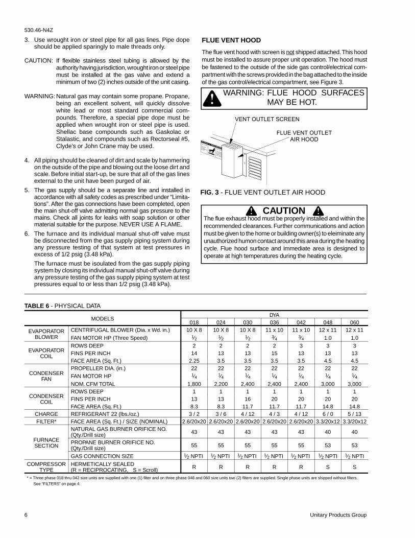
FLUE VENT HOOD
The flue vent hood with screen is not shipped attached. This hoodmust be installed to assure proper unit operation. The hood mustbe fastened to the outside of the side gas control/electrical com-partment with the screws provided in the bag attached to the insideof the gas control/electrical compartment, see Figure 3.
CAUTIONThe flue exhaust hood must be properly installed and within therecommended clearances. Further communications and actionmust be given to the home or building owner(s) to eleiminate anyunauthorized humon contact around this area during the heatingcycle. Flue hood surface and immediate area is designed tooperate at high temperatures during the heating cycle.
WARNING: FLUE HOOD SURFACESMAY BE HOT.
FIG. 3 - FLUE VENT OUTLET AIR HOOD
TABLE 6 - PHYSICAL DATA
MODELSDYA
018 024 030 036 042 048 060
EVAPORATORBLOWER
CENTRIFUGAL BLOWER (Dia. x Wd. in.) 10 X 8 10 X 8 10 X 8 11 x 10 11 x 10 12 x 11 12 x 11
FAN MOTOR HP (Three Speed) 1⁄2 1⁄2 1⁄2 3⁄4 3⁄4 1.0 1.0
EVAPORATORCOIL
ROWS DEEP 2 2 2 2 3 3 3FINS PER INCH 14 13 13 15 13 13 13FACE AREA (Sq. Ft.) 2.25 3.5 3.5 3.5 3.5 4.5 4.5
CONDENSERFAN
PROPELLER DIA. (in.) 22 22 22 22 22 22 22FAN MOTOR HP 1⁄4 1⁄4 1⁄4 1⁄4 1⁄4 1⁄4 1⁄4NOM. CFM TOTAL 1,800 2,200 2,400 2,400 2,400 3,000 3,000
CONDENSERCOIL
ROWS DEEP 1 1 1 1 1 1 1FINS PER INCH 13 13 16 20 20 20 20FACE AREA (Sq. Ft.) 8.3 8.3 11.7 11.7 11.7 14.8 14.8
CHARGE REFRIGERANT 22 (lbs./oz.) 3 / 2 3 / 6 4 / 12 4 / 3 4 / 12 6 / 0 5 / 13FILTER* FACE AREA (Sq. Ft.) / SIZE (NOMINAL) 2.6/20x20 2.6/20x20 2.6/20x20 2.6/20x20 2.6/20x20 3.3/20x12 3.3/20x12
FURNACESECTION
NATURAL GAS BURNER ORIFICE NO.(Qty./Drill size) 43 43 43 43 43 40 40
PROPANE BURNER ORIFICE NO.(Qty./Drill size) 55 55 55 55 55 53 53
GAS CONNECTION SIZE 1⁄2 NPTI 1⁄2 NPTI 1⁄2 NPTI 1⁄2 NPTI 1⁄2 NPTI 1⁄2 NPTI 1⁄2 NPTI
COMPRESSORTYPE
HERMETICALLY SEALED(R = RECIPROCATING, S = Scroll) R R R R R S S
* = Three phase 018 thru 042 size units are supplied with one (1) filter and on three phase 048 and 060 size units two (2) filters are supplied. Single phase units are shipped without filters. See “FILTERS” on page 4.
� � � � � � � � � � � �
� � � � � � � � �
� � � � � � �
530.46-N4Z
6 Unitary Products Group
491⁄825
24 471⁄4
CENTER OF GRAVITY
FRONTOF
UNIT
CORNER "C"
CORNER "D"
CORNER "A"
CORNER "B"FIG. 4 - CENTER OF GRAVITY
TABLE 7 - UNIT WEIGHTS
MODELDYA
UNITSHIPPINGWEIGHT
(lbs.)
UNITOPERATING
WEIGHT(lbs.)
CORNER OPERATING WEIGHTS(lbs., location, see Figure 4)
"A" "B" "C" "D"
018 365 360 91 88 89 92
024 365 360 91 88 89 92
030 395 390 98 95 96 99
036 400 395 100 96 98 101
042 405 410 104 100 101 105
048 475 470 119 115 116 120
060 480 475 120 116 117 122
TABLE 8 - ELECTRICAL DATA
MODELDYA
POWERSUPPLY
VOLTAGELIMITATIONS
➀COMPRESSOR COND.
FANMOTOR,
FLA
SUPPLYAIR
BLOWERMOTOR,
FLA
MINIMUMCIRCUIT
AMPACITY
MAX.FUSESIZE,AMPS
➁
MAX.HACR
BREAKERSIZE,AMPS
UNITPOWERFACTOR
TRANSFORMERSIZE (VA)
➂MIN. MAX. RLA LRA
018 208/230-1-60 187 253 9.0 48.0 1.1 2.2 14.5 20 20 .96 40024 208/230-1-60 187 253 11.5 60.0 1.1 2.2 17.7 25 25 .96 40030 208/230-1-60 187 253 14.7 73.0 1.1 2.2 21.7 30 30 .96 40036 208/230-1-60 187 253 17.3 94.0 1.1 3.5 26.2 35 35 .96 40042 208/230-1-60 187 253 20.5 120.0 1.1 3.5 30.2 40 40 .96 40048 208/230-1-60 187 253 24.4 140.0 1.3 7.0 38.8 50 50 .96 40060 208/230-1-60 187 253 32.1 169.0 1.3 7.0 48.4 70 70 .96 40036 208/230-3-60 187 253 10.9 78.0 1.1 3.5 18.2 25 25 .96 75042 208/230-3-60 187 253 14.1 110.0 1.1 3.5 22.2 30 30 .96 75048 208/230-3-60 187 253 14.1 105 1.3 7.0 25.9 35 35 .96 75060 208/230-3-60 187 253 19.3 123 1.3 7.0 32.4 45 45 .96 75036 460-3-60 414 504 5.8 40.0 0.6 1.8 9.6 15 15 .96 75042 460-3-60 414 504 7.1 54.0 0.6 1.8 11.2 15 15 .96 75048 460-3-60 414 504 7.1 55.0 0.7 3.5 13.1 20 20 .96 75060 460-3-60 414 504 10.0 62.0 0.7 3.5 16.7 25 25 .96 75036 575-3-60 518 630 4.5 32.0 0.4 1.5 7.5 15 15 .96 75042 575-3-60 518 630 5.8 44.0 0.4 1.5 9.1 15 15 .96 75048 575-3-60 518 630 5.7 45.0 0.6 2.8 10.5 15 15 .96 75060 575-3-60 518 630 7.9 50.0 0.6 2.8 13.3 20 20 .96 75
Note; Electrical data based on 104°F outdoor air ambient temperature.➀ = Utilization Range “A” in accordance with ARI Standard 110. ➁ = Dual element, time delay type.➂ = If economizer or motorized damper are to be used, 75 VA is required. Refer to price pages for future details.
530.46-N4Z
Unitary Products Group 7
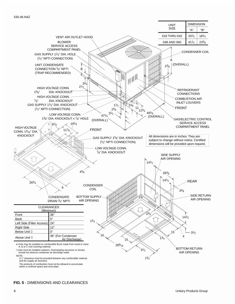
FIG. 5 - DIMENSIONS AND CLEARANCES
CLEARANCES(Minimum)
Front 36"Back 0"Left Side (Filter Access) 24"Right Side 12"Below Unit ➀ 0"
Above Unit ➁ 36" (For Condenser Air Discharge)
CONDENSERCOIL
154
REAR
SIDE RETURNAIR OPENING
SIDE SUPPLYAIR OPENING
BOTTOM RETURNAIR OPENING
15
141⁄2
283⁄8
33⁄8
31⁄2
289⁄16
21⁄2
23⁄8
13⁄4
13⁄4
13⁄4
31⁄215
141⁄2
141⁄2
BOTTOM SUPPLYAIR OPENING
B
A
23⁄8
GAS SUPPLY 11⁄4“ DIA. HOLE(1⁄2“ NPTI CONNECTION)
CONDENSER COIL
123⁄4491⁄8
471⁄4LOW VOLTAGE CONN.13⁄8“ DIA. KNOCKOUT x 7⁄8“ HOLE
HIGH VOLTAGE CONN.7⁄8“ DIA. KNOCKOUT
VENT AIR OUTLET HOOD
FRONT
COMBUSTION AIRINLET LOUVERS
GAS/ELECTRIC CONTROLSERVICE ACCESS
COMPARTMENT PANEL
BLOWERSERVICE ACCESS
COMPARTMENT PANEL
(OVERALL)
(OVERALL)
(OVERALL)
31⁄2
53⁄811⁄225⁄8
REFRIGERANTCONNECTIONS
GAS SUPPLY 11⁄4“ DIA. KNOCKOUT(1⁄2“ NPTI CONNECTION)
33⁄4
All dimensions are in inches. They aresubject to change without notice. Certifieddimensions will be provided upon request.
11
HIGH VOLTAGE CONN.13⁄8“ DIA. KNOCKOUT
UNIT CONDENSATECONNECTION 3⁄4“ NPTI(TRAP RECOMMENDED)
CONDENSATEDRAIN 3⁄4“ NPTI
LOW VOLTAGE CONN.7⁄8“ DIA. KNOCKOUT
HIGH VOLTAGECONN. 13⁄32“ DIA.
KNOCKOUTGAS SUPPLY 15⁄8“ DIA. KNOCKOUT
(1⁄2“ NPTI CONNECTION)
FRONT
191⁄4
117⁄8
87⁄8
6
45⁄8
263⁄4
UNITSIZE
DIMENSION
“A” “B”
018 THRU 042 331⁄2 181⁄4
048 AND 060 411⁄2 233⁄8
á Units may be installed on combustible floors made from wood or class A, B or C roof covering material.í Units must be installed outdoors. Overhanging structures or shrubs should not obstruct condenser air discharge outlet.NOTE: A 1" clearance must be provided between any combustible material and the supply air ductwork. The products of combustion must not be allowed to accumulate within a confined space and recirculate.
530.46-N4Z
8 Unitary Products Group
The unit is controlled by a conventional four wire heating/cool-ing thermostat common to this class of equipment.
HEATING
When the thermostat calls for "HEAT", the thermostat terminal"W" is energized, energizing the combustion air blower.
After airflow is established, the air proving switch closes, thehot surface ignitor is energized and the pilot valve opensigniting the pilot flame. The system will try to light the pilot for90 seconds. After 90 seconds, the pilot valve will close and thesystem will retry in 5 minutes.
The flame rod senses a flame and de-energizes the ignitoropening the main gas valve and the main burners light.
30 seconds after the main burners light the circulating fan isenergized at the heating speed.
When the thermostat is satisfied, terminal "W" is de-energized,de-energizing the ignition system closing the gas valve.
After a 5 second postpurge timing period, the combustion airblower is de-energized and the heat fan off timing begins.
When this field selected heat fan off timing is completed thecirculating fan is de-energized.
If the primary, rollout or auxiliary limit switches open, thethermostat and ignition system is de-energized and the gasvalve closes. The combustion blower and the circulating fan, atheat speed, are energized.
The combustion blower remains energized for the 5 secondpostpurge timing period if the primary, rollout or auxiliary limit
switches remake the contact (the rollout and auxiliary limitswitches must be manually reset). The circulating fan remainsenergized for the selected heat delay off timing.
Normal operation of the system resumes.
COOLING
When the thermostat calls for "COOL", the thermostat termi-nals "G" and "Y" are energized signaling the compressor andoutdoor fan to run.
After a cool fan on delay timing of 2 seconds, the circulating fanis energized at cooling speed.
When the thermostat is satisfied, terminals "G" and "Y" arede-energized, de-energizing the compressor and outdoor fan.
After a cool fan off delay timing of 30 seconds the circulatingfan is de-energized.
CIRCULATING FAN
When the thermostat calls for "FAN", the thermostat terminal"G" is energized signaling the circulating fan to run at the heatspeed 2 seconds after the "G" terminal is energized.
If a call for "HEAT" occurs, the circulating fan continues to runat the heat speed.
If a call for "COOL" occurs, the circulating fan switches to coolspeed after a 4 second delay.
When the thermostat ends the call for "FAN", the thermostatterminal "G" is de-energized, de-energizing the circulating fan.
SEQUENCE OF OPERATION
START-UPPRE-START CHECK LIST
Complete the following checks before starting the unit.
1. Check the type of gas being supplied. Be sure that it is thesame as listed on the unit nameplate.
2. Make sure that the vent outlet air hoods has been properlyinstalled.
OPERATING INSTRUCTIONS
1. STOP! Read the information on the unit safety label.
2. Set the thermostat to the “OFF” position.
3. Turn off all electrical power to the unit.
4. DO NOT try to light the burners by hand. This appliance isequipped with an ignition device which automatically lightsthe burners.
5. Remove the access panel.
6. Turn the gas valve switch to the “OFF” position.
7. Wait five (5) minutes to clear out any gas. If you then smellgas, STOP! Follow “B” in the information on the unit safetylabel. If you don’t smell gas, go to the next step.
8. Turn the gas valve switch to the “ON” position.
9. Replace the control access panel.
10. Turn on all electric power to the unit.
11. Set the thermostat to the desired setting.
12. If the unit will not operate, follow the instructions “To TurnOff Gas To Appliance” and call your service technician orgas supplier.
TO TURN OFF GAS TO UNIT1. Set the thermostat to the “OFF” position.
2. Turn off all electric power to the appliance if service is to beperformed.
3. Remove the control access panel.
4. Turn the gas valve switch to the “OFF” position. DO NOTFORCE.
5. Replace the control access panel.
POST-START CHECK LIST (GAS)
After the entire control circuit has been energized and theheating section is operating, make the following checks:
1. Check for gas leaks in the unit piping as well as the supply
530.46-N4Z
Unitary Products Group 9
2. Check for correct manifold gas pressures. See “CheckingGas Input”.
3. Check the supply gas pressure. It must be within the limitsshown on rating nameplate. Supply pressure should bechecked with all gas appliances in the building at full fire. Atno time should the standby gas line pressure exceed 10.5",nor the operating pressure drop below 4.5" for natural gasunits. If gas pressure is outside these limits, contact thelocal gas utility for corrective action.
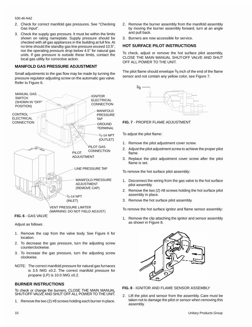
MANIFOLD GAS PRESSURE ADJUSTMENT
Small adjustments to the gas flow may be made by turning thepressure regulator adjusting screw on the automatic gas valve.Refer to Figure 6.
Adjust as follows:
1. Remove the cap from the valve body. See Figure 6 forlocation.
2. To decrease the gas pressure, turn the adjusting screwcounterclockwise.
3. To increase the gas pressure, turn the adjusting screwclockwise.
NOTE: The correct manifold pressure for natural gas furnacesis 3.5 IWG ±0.2. The correct manifold pressure forpropane (LP) is 10.0 IWG ±0.2.
BURNER INSTRUCTIONS
To check or change the burners, CLOSE THE MAIN MANUALSHUT-OFF VALVE AND SHUT OFF ALL POWER TO THE UNIT.
1. Remove the two (2) #8 screws holding each burner in place.
2. Remove the burner assembly from the manifold assemblyby moving the burner assembly forward, turn at an angleand pull back.
3. Burners are now accessible for service.
HOT SURFACE PILOT INSTRUCTIONS
To check, adjust or remove the hot surface pilot assembly,CLOSE THE MAIN MANUAL SHUT-OFF VALVE AND SHUTOFF ALL POWER TO THE UNIT.
The pilot flame should envelope 3⁄8 inch of the end of the flamesensor and not contain any yellow color, see Figure 7.
To adjust the pilot flame:
1. Remove the pilot adjustment cover screw.
2. Adjust the pilot adjustment screw to achieve the proper pilotflame.
3. Replace the pilot adjustment cover screw after the pilotflame is set.
To remove the hot surface pilot assembly:
1. Disconnect the wiring from the gas valve to the hot surfacepilot assembly.
2. Remove the two (2) #8 screws holding the hot surface pilotassembly in place.
3. Remove the hot surface pilot assembly.
To remove the hot surface ignitor and flame sensor assembly:
1. Remove the clip attaching the ignitor and sensor assemblyas shown in Figure 8.
2. Lift the pilot and sensor from the assembly. Care must betaken not to damage the pilot or sensor when removing thisassembly.
FIG. 6 - GAS VALVE
FIG. 7 - PROPER FLAME ADJUSTMENT
FIG. 8 - IGNITOR AND FLAME SENSOR ASSEMBLY
3⁄8MANUAL GASSWITCH(SHOWN IN “OFF”POSITION)
PILOTADJUSTMENT
MANIFOLDPRESSURETAP
1⁄2-14 NPT(OUTLET)
PILOT GASCONNECTION
IGNITORELECTRICALCONNECTION
CONTROLELECTRICALCONNECTION GROUND
TERMINAL
1⁄2-14 NPT(INLET)
LINE PRESSURE TAP
VENT PRESSURE LIMITER(WARNING: DO NOT FIELD ADJUST)
MANIFOLD PRESSUREADJUSTMENT(REMOVE CAP)
530.46-N4Z
10 Unitary Products Group
3. After maintenance of the pilot assembly, always measurethe resistance across the ignitor. If the resistance is greaterthan 10 ohms, discard the ignitor and replace it with a newignitor.
ADJUSTMENT OF TEMPERATURE RISE
The temperature rise (or temperature difference between thereturn air and the heated air from the furnace) must lie withinthe range shown on the rating plate and the data in Tables 2and 3.
After the temperature rise has been determined, the CFM canbe calculated as follows:
After about 20 minutes of operation, determine the furnacetemperature rise. Take readings of both the return air and theheated air in the ducts about six feet from the furnace wherethey will not be affected by radiant heat. Increase the blowerCFM to decrease the temperature rise; decrease the blowerCFM to increase the rise.
DIRECT DRIVE BLOWER
All units have direct drive multi-speed blower motors. Refer tothe unit wiring diagram and connect the blower motor for thedesired CFM.
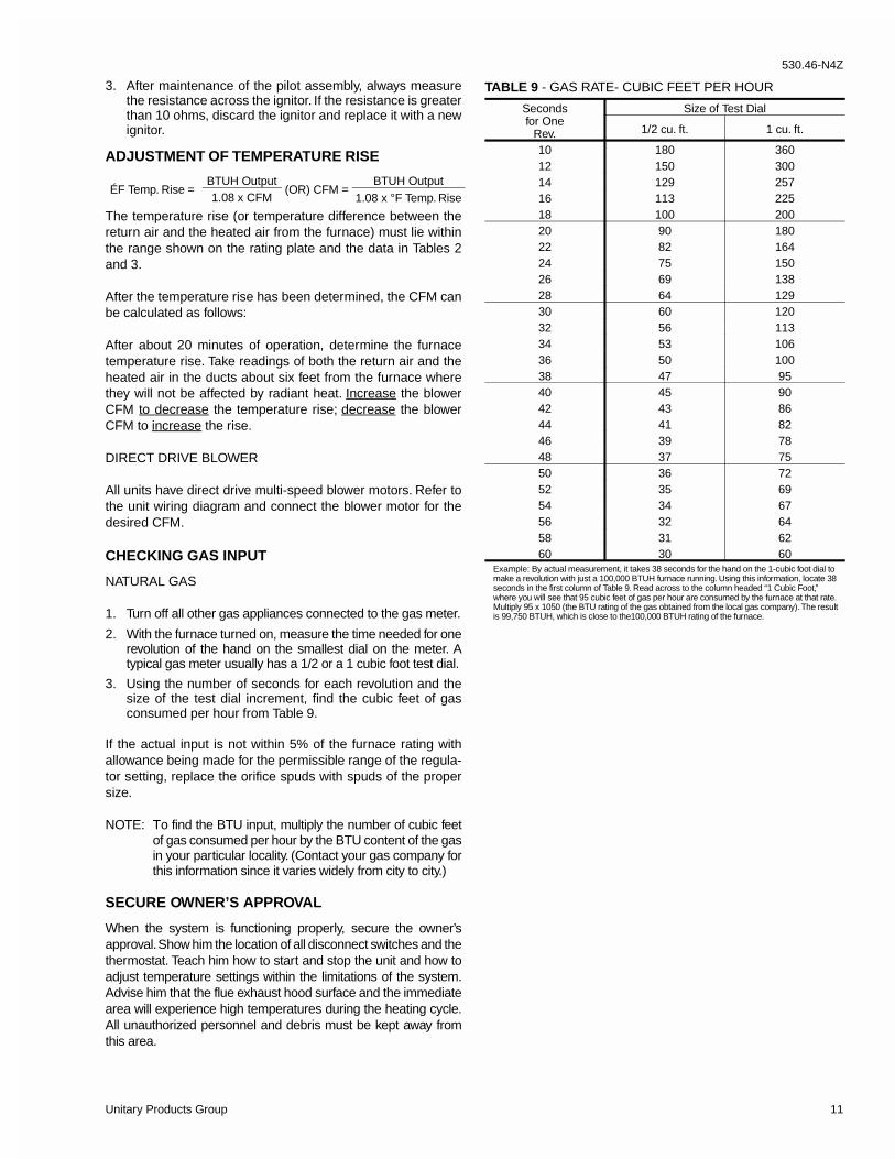
CHECKING GAS INPUT
NATURAL GAS
1. Turn off all other gas appliances connected to the gas meter.
2. With the furnace turned on, measure the time needed for onerevolution of the hand on the smallest dial on the meter. Atypical gas meter usually has a 1/2 or a 1 cubic foot test dial.
3. Using the number of seconds for each revolution and thesize of the test dial increment, find the cubic feet of gasconsumed per hour from Table 9.
If the actual input is not within 5% of the furnace rating withallowance being made for the permissible range of the regula-tor setting, replace the orifice spuds with spuds of the propersize.
NOTE: To find the BTU input, multiply the number of cubic feetof gas consumed per hour by the BTU content of the gasin your particular locality. (Contact your gas company forthis information since it varies widely from city to city.)
SECURE OWNER’S APPROVAL
When the system is functioning properly, secure the owner’sapproval. Show him the location of all disconnect switches and thethermostat. Teach him how to start and stop the unit and how toadjust temperature settings within the limitations of the system.Advise him that the flue exhaust hood surface and the immediatearea will experience high temperatures during the heating cycle.All unauthorized personnel and debris must be kept away fromthis area.
ÉF Temp. Rise = BTUH Output
(OR) CFM =BTUH Output
1.08 x CFM 1.08 x °F Temp. Rise
TABLE 9 - GAS RATE- CUBIC FEET PER HOUR
Secondsfor One
Rev.
Size of Test Dial
1/2 cu. ft. 1 cu. ft.
10 180 36012 150 30014 129 25716 113 22518 100 20020 90 18022 82 16424 75 15026 69 13828 64 12930 60 12032 56 11334 53 10636 50 10038 47 9540 45 9042 43 8644 41 8246 39 7848 37 7550 36 7252 35 6954 34 6756 32 6458 31 6260 30 60
Example: By actual measurement, it takes 38 seconds for the hand on the 1-cubic foot dial tomake a revolution with just a 100,000 BTUH furnace running. Using this information, locate 38seconds in the first column of Table 9. Read across to the column headed “1 Cubic Foot,”where you will see that 95 cubic feet of gas per hour are consumed by the furnace at that rate.Multiply 95 x 1050 (the BTU rating of the gas obtained from the local gas company). The resultis 99,750 BTUH, which is close to the100,000 BTUH rating of the furnace.
530.46-N4Z
Unitary Products Group 11
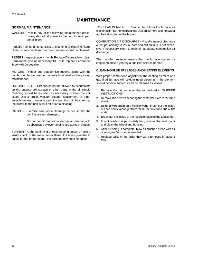
NORMAL MAINTENANCE
WARNING: Prior to any of the following maintenance proce-dures, shut off all power to the unit, to avoid per-sonal injury.
Periodic maintenance consists of changing or cleaning filters.Under some conditions, the main burners should be cleaned.
FILTERS - Inspect once a month. Replace Disposable or cleanPermanent Type as necessary. DO NOT replace PermanentType with Disposable.
MOTORS - Indoor and outdoor fan motors, along with thecombustion blower are permanently lubricated and require nomaintenance.
OUTDOOR COIL - Dirt should not be allowed to accumulateon the outdoor coil surface or other parts in the air circuit.Cleaning should be as often as necessary to keep the coilclean. Use a brush, vacuum cleaner attachment, or othersuitable means. If water is used to clean the coil, be sure thatthe power to the unit is shut off prior to cleaning.
CAUTION: Exercise care when cleaning the coil so that thecoil fins are not damaged.
Do not permit the hot condenser air discharge tobe obstructed by overhanging structures or shrubs.
BURNER - At the beginning of each heating season, make avisual check of the main burner flame. If it is not possible toadjust for the proper flame, the burners may need cleaning.
TO CLEAN BURNERS - Remove them from the furnace asexplained in “Burner Instructions”. Clean burners with hot waterapplied along top of the burner.
COMBUSTION AIR DISCHARGE - Visually inspect dischargeoutlet periodically to insure soot and dirt buildup is not exces-sive. If necessary, clean to maintain adequate combustion airdischarge.
The manufacture recommends that the furnace system beinspected once a year by a qualified service person.
CLEANING FLUE PASSAGES AND HEATING ELEMENTS
With proper combustion adjustment the heating element of agas fired furnace will seldom need cleaning. If the elementshould become sooted, it can be cleaned as follows:
1. Remove the burner assembly as outlined in “BURNERINSTRUCTIONS”.
2. Remove the screws securing the restrictor plate to the tubesheet.
3. Using a wire brush on a flexible wand, brush out the insideof each heat exchanger from the burner inlet and flue outletends.
4. Brush out the inside of the restrictor plate to the tube sheet.
5. If soot build-up is particularly bad, remove the vent motorand clean the wheel and housing.
6. After brushing is complete, blow all brushed areas with airor nitrogen. Vacuum as needed.
7. Replace parts in the order they were removed in steps 1thru 3.
MAINTENANCE530.46-N4Z
12 Unitary Products Group
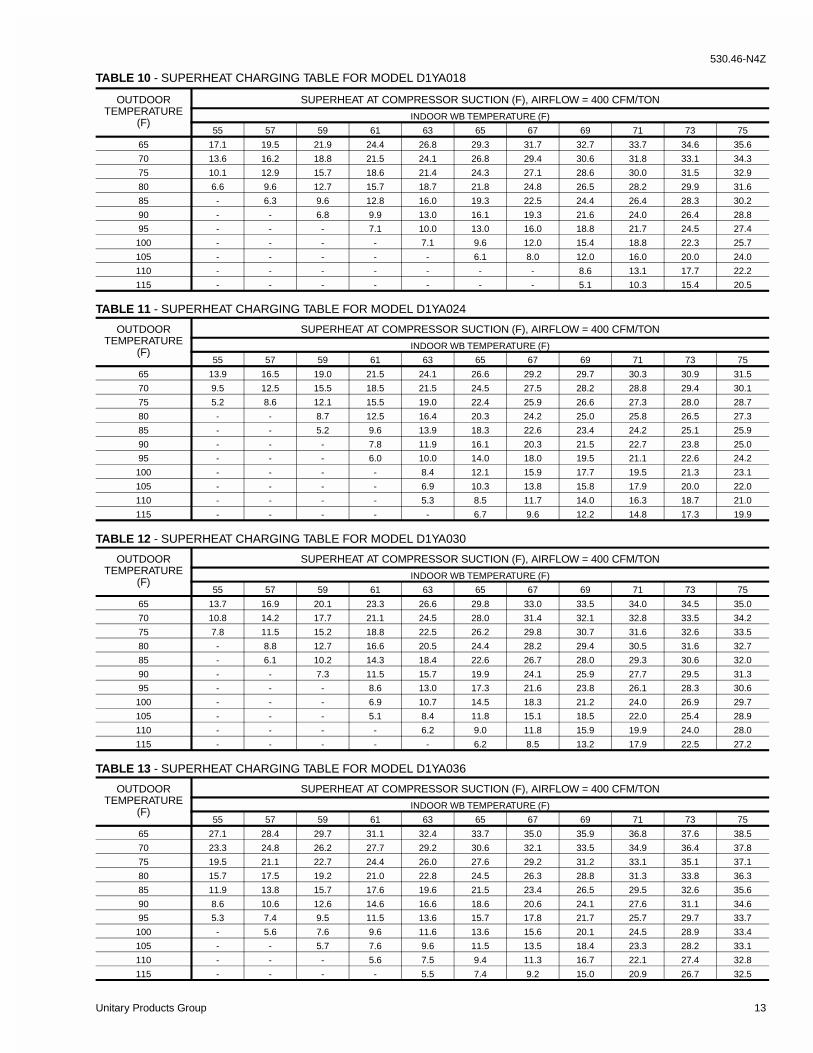
TABLE 11 - SUPERHEAT CHARGING TABLE FOR MODEL D1YA024
OUTDOORTEMPERATURE
(F)
SUPERHEAT AT COMPRESSOR SUCTION (F), AIRFLOW = 400 CFM/TON
INDOOR WB TEMPERATURE (F)
55 57 59 61 63 65 67 69 71 73 75
65 13.9 16.5 19.0 21.5 24.1 26.6 29.2 29.7 30.3 30.9 31.5
70 9.5 12.5 15.5 18.5 21.5 24.5 27.5 28.2 28.8 29.4 30.1
75 5.2 8.6 12.1 15.5 19.0 22.4 25.9 26.6 27.3 28.0 28.7
80 - - 8.7 12.5 16.4 20.3 24.2 25.0 25.8 26.5 27.3
85 - - 5.2 9.6 13.9 18.3 22.6 23.4 24.2 25.1 25.9
90 - - - 7.8 11.9 16.1 20.3 21.5 22.7 23.8 25.0
95 - - - 6.0 10.0 14.0 18.0 19.5 21.1 22.6 24.2
100 - - - - 8.4 12.1 15.9 17.7 19.5 21.3 23.1
105 - - - - 6.9 10.3 13.8 15.8 17.9 20.0 22.0
110 - - - - 5.3 8.5 11.7 14.0 16.3 18.7 21.0
115 - - - - - 6.7 9.6 12.2 14.8 17.3 19.9
TABLE 12 - SUPERHEAT CHARGING TABLE FOR MODEL D1YA030
OUTDOORTEMPERATURE
(F)
SUPERHEAT AT COMPRESSOR SUCTION (F), AIRFLOW = 400 CFM/TON
INDOOR WB TEMPERATURE (F)
55 57 59 61 63 65 67 69 71 73 75
65 13.7 16.9 20.1 23.3 26.6 29.8 33.0 33.5 34.0 34.5 35.0
70 10.8 14.2 17.7 21.1 24.5 28.0 31.4 32.1 32.8 33.5 34.2
75 7.8 11.5 15.2 18.8 22.5 26.2 29.8 30.7 31.6 32.6 33.5
80 - 8.8 12.7 16.6 20.5 24.4 28.2 29.4 30.5 31.6 32.7
85 - 6.1 10.2 14.3 18.4 22.6 26.7 28.0 29.3 30.6 32.0
90 - - 7.3 11.5 15.7 19.9 24.1 25.9 27.7 29.5 31.3
95 - - - 8.6 13.0 17.3 21.6 23.8 26.1 28.3 30.6
100 - - - 6.9 10.7 14.5 18.3 21.2 24.0 26.9 29.7
105 - - - 5.1 8.4 11.8 15.1 18.5 22.0 25.4 28.9
110 - - - - 6.2 9.0 11.8 15.9 19.9 24.0 28.0
115 - - - - - 6.2 8.5 13.2 17.9 22.5 27.2
TABLE 10 - SUPERHEAT CHARGING TABLE FOR MODEL D1YA018
OUTDOORTEMPERATURE
(F)
SUPERHEAT AT COMPRESSOR SUCTION (F), AIRFLOW = 400 CFM/TON
INDOOR WB TEMPERATURE (F)
55 57 59 61 63 65 67 69 71 73 75
65 17.1 19.5 21.9 24.4 26.8 29.3 31.7 32.7 33.7 34.6 35.6
70 13.6 16.2 18.8 21.5 24.1 26.8 29.4 30.6 31.8 33.1 34.3
75 10.1 12.9 15.7 18.6 21.4 24.3 27.1 28.6 30.0 31.5 32.9
80 6.6 9.6 12.7 15.7 18.7 21.8 24.8 26.5 28.2 29.9 31.6
85 - 6.3 9.6 12.8 16.0 19.3 22.5 24.4 26.4 28.3 30.2
90 - - 6.8 9.9 13.0 16.1 19.3 21.6 24.0 26.4 28.8
95 - - - 7.1 10.0 13.0 16.0 18.8 21.7 24.5 27.4
100 - - - - 7.1 9.6 12.0 15.4 18.8 22.3 25.7
105 - - - - - 6.1 8.0 12.0 16.0 20.0 24.0
110 - - - - - - - 8.6 13.1 17.7 22.2
115 - - - - - - - 5.1 10.3 15.4 20.5
TABLE 13 - SUPERHEAT CHARGING TABLE FOR MODEL D1YA036
OUTDOORTEMPERATURE
(F)
SUPERHEAT AT COMPRESSOR SUCTION (F), AIRFLOW = 400 CFM/TON
INDOOR WB TEMPERATURE (F)
55 57 59 61 63 65 67 69 71 73 75
65 27.1 28.4 29.7 31.1 32.4 33.7 35.0 35.9 36.8 37.6 38.5
70 23.3 24.8 26.2 27.7 29.2 30.6 32.1 33.5 34.9 36.4 37.8
75 19.5 21.1 22.7 24.4 26.0 27.6 29.2 31.2 33.1 35.1 37.1
80 15.7 17.5 19.2 21.0 22.8 24.5 26.3 28.8 31.3 33.8 36.3
85 11.9 13.8 15.7 17.6 19.6 21.5 23.4 26.5 29.5 32.6 35.6
90 8.6 10.6 12.6 14.6 16.6 18.6 20.6 24.1 27.6 31.1 34.6
95 5.3 7.4 9.5 11.5 13.6 15.7 17.8 21.7 25.7 29.7 33.7
100 - 5.6 7.6 9.6 11.6 13.6 15.6 20.1 24.5 28.9 33.4
105 - - 5.7 7.6 9.6 11.5 13.5 18.4 23.3 28.2 33.1
110 - - - 5.6 7.5 9.4 11.3 16.7 22.1 27.4 32.8
115 - - - - 5.5 7.4 9.2 15.0 20.9 26.7 32.5
530.46-N4Z
Unitary Products Group 13
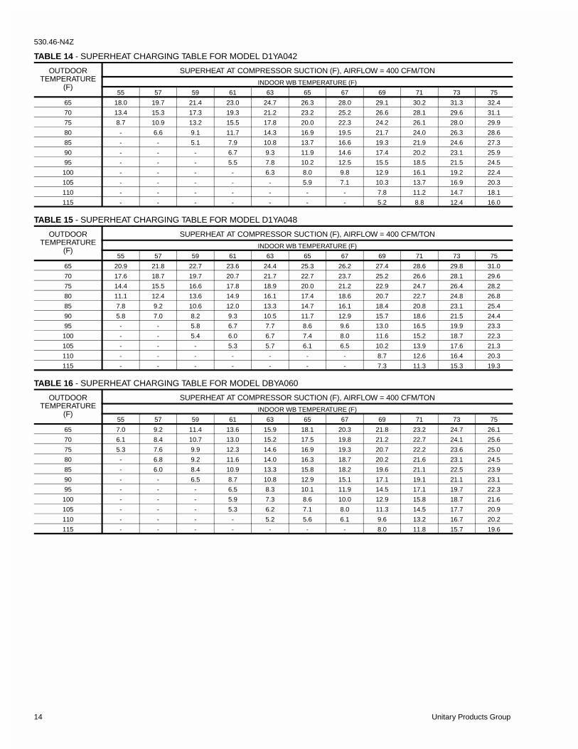
TABLE 14 - SUPERHEAT CHARGING TABLE FOR MODEL D1YA042
OUTDOORTEMPERATURE
(F)
SUPERHEAT AT COMPRESSOR SUCTION (F), AIRFLOW = 400 CFM/TON
INDOOR WB TEMPERATURE (F)
55 57 59 61 63 65 67 69 71 73 75
65 18.0 19.7 21.4 23.0 24.7 26.3 28.0 29.1 30.2 31.3 32.4
70 13.4 15.3 17.3 19.3 21.2 23.2 25.2 26.6 28.1 29.6 31.1
75 8.7 10.9 13.2 15.5 17.8 20.0 22.3 24.2 26.1 28.0 29.9
80 - 6.6 9.1 11.7 14.3 16.9 19.5 21.7 24.0 26.3 28.6
85 - - 5.1 7.9 10.8 13.7 16.6 19.3 21.9 24.6 27.3
90 - - - 6.7 9.3 11.9 14.6 17.4 20.2 23.1 25.9
95 - - - 5.5 7.8 10.2 12.5 15.5 18.5 21.5 24.5
100 - - - - 6.3 8.0 9.8 12.9 16.1 19.2 22.4
105 - - - - - 5.9 7.1 10.3 13.7 16.9 20.3
110 - - - - - - - 7.8 11.2 14.7 18.1
115 - - - - - - - 5.2 8.8 12.4 16.0
TABLE 15 - SUPERHEAT CHARGING TABLE FOR MODEL D1YA048
OUTDOORTEMPERATURE
(F)
SUPERHEAT AT COMPRESSOR SUCTION (F), AIRFLOW = 400 CFM/TON
INDOOR WB TEMPERATURE (F)
55 57 59 61 63 65 67 69 71 73 75
65 20.9 21.8 22.7 23.6 24.4 25.3 26.2 27.4 28.6 29.8 31.0
70 17.6 18.7 19.7 20.7 21.7 22.7 23.7 25.2 26.6 28.1 29.6
75 14.4 15.5 16.6 17.8 18.9 20.0 21.2 22.9 24.7 26.4 28.2
80 11.1 12.4 13.6 14.9 16.1 17.4 18.6 20.7 22.7 24.8 26.8
85 7.8 9.2 10.6 12.0 13.3 14.7 16.1 18.4 20.8 23.1 25.4
90 5.8 7.0 8.2 9.3 10.5 11.7 12.9 15.7 18.6 21.5 24.4
95 - - 5.8 6.7 7.7 8.6 9.6 13.0 16.5 19.9 23.3
100 - - 5.4 6.0 6.7 7.4 8.0 11.6 15.2 18.7 22.3
105 - - - 5.3 5.7 6.1 6.5 10.2 13.9 17.6 21.3
110 - - - - - - - 8.7 12.6 16.4 20.3
115 - - - - - - - 7.3 11.3 15.3 19.3
TABLE 16 - SUPERHEAT CHARGING TABLE FOR MODEL DBYA060
OUTDOORTEMPERATURE
(F)
SUPERHEAT AT COMPRESSOR SUCTION (F), AIRFLOW = 400 CFM/TON
INDOOR WB TEMPERATURE (F)
55 57 59 61 63 65 67 69 71 73 75
65 7.0 9.2 11.4 13.6 15.9 18.1 20.3 21.8 23.2 24.7 26.1
70 6.1 8.4 10.7 13.0 15.2 17.5 19.8 21.2 22.7 24.1 25.6
75 5.3 7.6 9.9 12.3 14.6 16.9 19.3 20.7 22.2 23.6 25.0
80 - 6.8 9.2 11.6 14.0 16.3 18.7 20.2 21.6 23.1 24.5
85 - 6.0 8.4 10.9 13.3 15.8 18.2 19.6 21.1 22.5 23.9
90 - - 6.5 8.7 10.8 12.9 15.1 17.1 19.1 21.1 23.1
95 - - - 6.5 8.3 10.1 11.9 14.5 17.1 19.7 22.3
100 - - - 5.9 7.3 8.6 10.0 12.9 15.8 18.7 21.6
105 - - - 5.3 6.2 7.1 8.0 11.3 14.5 17.7 20.9
110 - - - - 5.2 5.6 6.1 9.6 13.2 16.7 20.2
115 - - - - - - - 8.0 11.8 15.7 19.6
530.46-N4Z
14 Unitary Products Group
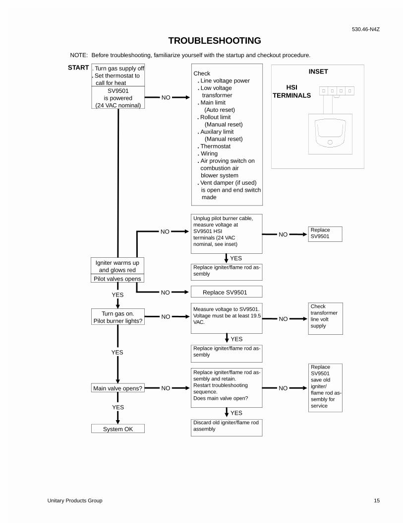
TROUBLESHOOTING
YES
. Turn gas supply off
. Set thermostat to call for heat
SV9501is powered
(24 VAC nominal)
Igniter warms upand glows red
Pilot valves opens
Turn gas on.Pilot burner lights?
Check . Line voltage power . Low voltage
transformer . Main limit
(Auto reset) . Rollout limit
(Manual reset) . Auxilary limit
(Manual reset) . Thermostat . Wiring . Air proving switch on combustion air blower system
. Vent damper (if used) is open and end switch
made
Unplug pilot burner cable,measure voltage atSV9501 HSIterminals (24 VACnominal, see inset)
Replace igniter/flame rod as-sembly
Replace SV9501
Measure voltage to SV9501.Voltage must be at least 19.5VAC.
NO
NO
NO
NOYES
NO
NO
Main valve opens?
System OK
Replace igniter/flame rod as-sembly
Replace igniter/flame rod as-sembly and retain.Restart troubleshootingsequence.Does main valve open?
Discard old igniter/flame rodassembly
YES
YES
NONO
INSET
HSITERMINALS
START
YES
YES
ReplaceSV9501
Checktransformerline voltsupply
ReplaceSV9501save oldigniter/flame rod as-sembly forservice
NOTE: Before troubleshooting, familiarize yourself with the startup and checkout procedure.
530.46-N4Z
Unitary Products Group 15
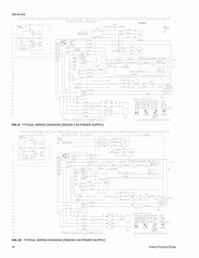
FIG. 9 - TYPICAL WIRING DIAGRAM (208/230-1-60 POWER SUPPLY)
FIG. 10 - TYPICAL WIRING DIAGRAM (208/230-3-60 POWER SUPPLY)
(See page 18)
530.46-N4Z
16 Unitary Products Group
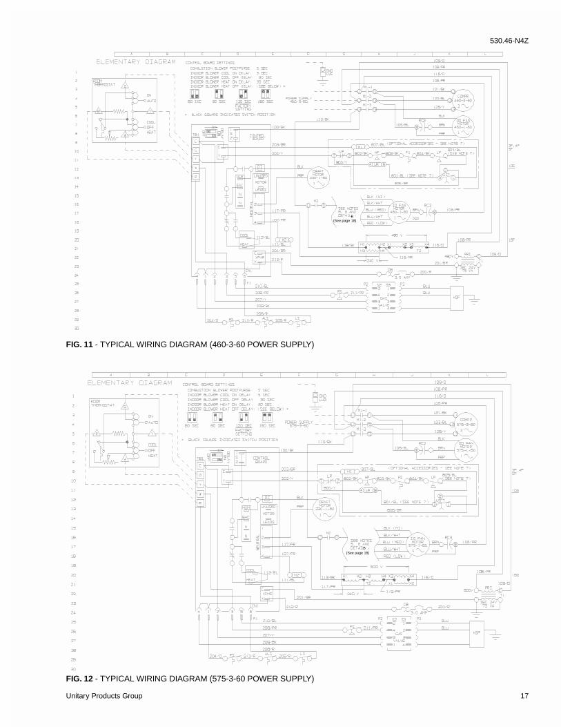
FIG. 11 - TYPICAL WIRING DIAGRAM (460-3-60 POWER SUPPLY)
FIG. 12 - TYPICAL WIRING DIAGRAM (575-3-60 POWER SUPPLY)
(See page 18)B
(See page 18)B
530.46-N4Z
Unitary Products Group 17
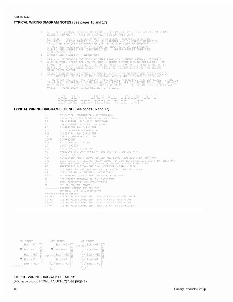
TYPICAL WIRING DIAGRAM NOTES (See pages 16 and 17)
TYPICAL WIRING DIAGRAM LEGEND (See pages 16 and 17)
FIG. 13 - WIRING DIAGRAM DETAIL “B”(460 & 575-3-60 POWER SUPPLY) See page 17
530.46-N4Z
18 Unitary Products Group

NOTES530.46-N4Z
Unitary Products Group 19

Subject to change without notice. Printed in U.S.A.Copyright by Unitary Products Group 1999. All rights reserved. 530.46-N4Z
5005 InterstateDriveNorth
NormanOklahoma73069
UnitaryProductsGroup