Embed Size (px)
Citation preview

GR - UM -140-A- 01
Growatt 10000TL3-S
Growatt 12000TL3-S
Growatt 9000TL3-S
Growatt 12000TL3
Growatt 8000TL3-S
Growatt 7000TL3-S
Growatt 6000TL3-S
Growatt 5000TL3-S
Growatt 4000TL3-S
Growatt 3000TL3-S
Growatt 11000TL3-S
Growatt 13000TL3-S
Growatt 15000TL3-S
Installation &
Operation Manual
Shenzhen Growatt New Energy Technology CO.,LTD
No.28 Guangming Road, Longteng Community, Shiyan, Bao'an District, Shenzhen, P.R.China
+ 86 755 2747 1942
[email protected] www.ginverter.com
T
E
W

Information on this Manual
1.1Documents use
1.2 Symbols Used
1.3 Glossary
Safety
2.1 Intended Use
Product Description
3.1 Inverter overview
3.2 Type label
3.3 Size and weight
3.4 Transportation
Unpacking
Index
1
2
3
4
2.2 Safety Precautions
Installation5 5.1 Safety instruction
5.2 Selecting the Installation Location
2.3 Assembly Warnings
2.4 Electrical Connection Warnings
2.5 Operation Warnings
2.6 Symbols on the inverter
3.5 Storage of Inverter
3.6 The advantage of the inverter
5.3 Installation guide
5.4 Electrical Connections
5.5 Grid Type
Start-Up and shut down the inverter
7 7.1 Start-Up the inverter
7.2 Shut down the Inverter
Commissioning6 6.1 Commission the Inverter
6.2 Operation Modes
6.3 Country Setting and LCD Display
6.4 Double MPPT of the TL3-S
6.5 Communication
Maintenance and Cleaning8 8.1 Cleaning the Inverter
8.2 Checking the DC Disconnect
Trouble shooting 9
10.1 Dismantling the Inverter
10.2 Packing the Inverter
Decommissioning10
10.3 Disposing of the Inverter
Specification11
Certificates
PV system installation12
13
11 .1 Specification of TL3-S
11.2 DC connector info
11 .3 Torque Values
11.4 Spare Parts and Accessories
Contact14
9.1 Error Messages displayed on LCD
9.2 System fault
9.3 Inverter warning
9.4 Inverter fault
12.1 Single inverter
12.2 Multi inverters

Store this manual where it will be accessible at all times. We assume no liability for
any damage caused by failure to observe these instructions. For possible changes in
this manual, SHENZHEN GROWATT NEW ENERGY TECHNOLOGY CO.,LTD accepts no
responsibilities to inform the users.
Information on this Manual1
1.1 Documents use
1.1.2 Target Group
1.1.3 Storage of the manual
This installation guide contains installation, commissioning, communication, trouble
shooting. Information of Growatt TL3-S series inverters:
This manual is for qualified persons who will operate, maintenance, service and
repaired inverters.
With this installation guide, users are able to install and operate the inverters easily.
This manual does not cover any details concerning equipment connected to the
inverter. Store this manual where accessible at all times.
1.1.1 Validity
WARNING
CAUTION
NOTICE
Information
WARNING indicates a hazardous situation which, if not
avoided, could result in death or serious injury.
WARNING indicates a hazardous situation which, if not
avoided, could result in death or serious injury.
NOTICE indicates a situation which, if not avoided, could result
in property damage.
Information that you must read and know to ensure optimal
operation of the system.
1 2
1.2 Symbols Used
The following types of safety instructions and general information appear in this
document as described below:
Symbol Description
Read the manual
DANGER
DANGER indicates a hazardous situation which, if not avoided,
will result in death or serious injury.
Growatt 3000TL3-S
Growatt 4000TL3-S
Growatt 5000TL3-S
Growatt 6000TL3-S
Growatt 7000TL3-S
Growatt 8000TL3-S
Growatt 9000TL3-S
Growatt 10000TL3-S
Growatt 11000TL3-S
Growatt 12000TL3
Growatt 12000TL3-S
Growatt 13000TL3-S
Growatt 15000TL3-S
1.1.4 Additional InformationFor further information on special topics in the download area at www.ginverter.com
1.3 Glossary
AC
Abbreviation for "Alternating Current"
DC
Abbreviation for "Direct Current"
Energy
Energy is measured in Wh (watt hours), kWh (kilowatt hours) or MWh (megawatt
hours).

Safety 2 2.1 Intended Use
TL3-S series inverters are grid-tied inverters which convert DC current generated by
PV modules into AC current and feed it into the public grid in three-phase. TL3-S
series inverters are multi-string inverters with multi-MPP trackers, which mean they
are able to connect to different PV module arrays.
The inverter may only be operated with a permanent connection to the public power
grid. The inverter is not intended for mobile use. Any other or additional use is not
considered as intended use. The manufacturer/supplier is not responsible for any
damages resulting from unintended use. Damage caused by such unintended use is
at the sole risk of the operator.
As drawings shown above, a complete Grid-tied PV system consists of PV modules,
DC fuse or breaker (only for France, the other country is optional), PV inverters,
public grid and other components. Moreover, PV inverters always act as key
components.
PV modules Capacitive Discharge Currents
PV modules with large capacities relative to earth, such as thin-film PV modules with
cells on a metallic substrate, may only be used if their coupling capacity does not
exceed 2.2uF. During feed-in operation, a leakage current flows from the cells to
earth, the size of which depends on the manner in which the PV modules are installed
(e.g. foil on metal roof) and on the weather (rain, snow). This "normal" leakage
current may not exceed 100mA due to the fact that the inverter would otherwise
automatically disconnect from the electricity grid as a protective measure.
3 4
Grid-tied PV system Overview:
Fig1.1
When design a PV system contains any Growatt inverters, the system designing
software “ShineDesign” (download from site: www.ginverter.com) will provide
adequate supports.
Power is measured in W (watts), kW (kilowatts) or MW (megawatts). Power is an
instantaneous value. It displays the power your inverter is currently feeding into the
power distribution grid.
Power rate
Power rate is the radio of current power feeding into the power distribution grid and
the maximum power of the inverter that can feed into the power distribution grid.
Power Factor
Power factor is the ratio of true power or watts to apparent power.
PV
Abbreviation for photovoltaic
Wireless communication accessories (optional)
The external wireless communication technology is a radio technology that allows
the inverter and other communication products to communicate with each other.
Power
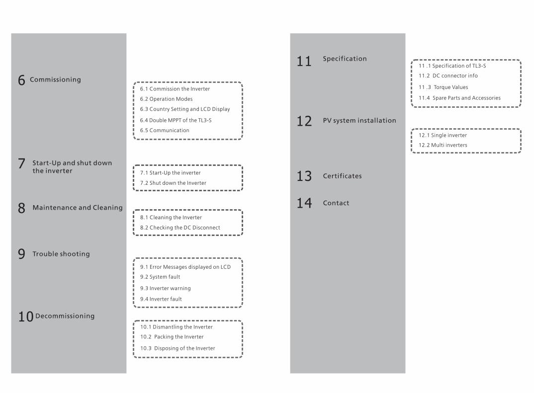
WARNING
Make all electrical connections (e.g. conductor termination, fuses,
PE connection, etc.) in accordance with prevailing regulations.
When working with the inverter powered on, adhere to all
prevailing safety regulations to minimize risk of accidents.The inverter may only be operated with PV generators (modules and
cabling) with protective insulation. Do not connect any source other
than PV modules to the inverter.Systems with inverters typically require additional control (e.g.,
switches, disconnects) or protective devices (e.g., fuse, circuit
breaker) depending upon the prevailing safety rules.
CAUTION
Housegrid:
Public grid:
Energy flows into the house grid. The consumers connected,
for example, household devices or lighting, consume the
energy. The energy left over is fed into the public grid. When
the UE series inverters do not generate any energy, e.g., at
night, the consumers which are connected are supplied by the
public grid. The energy displayed on the LCD of inverter is for
reference only. When energy is fed into the public grid, the
energy meter spins backwards.
Energy is fed directly into the public grid. The UE series
inverters need install a separate energy meter. The energy
produced is compensated at a rate depending on the electric
power company.
2.5 Operation Warnings
WARNING
Ensure all covers and doors are closed and secure during operation.Although designed to meet all safety requirements, some parts and
surfaces of Inverter are still hot during operation. To reduce the risk
of injury, do not touch the heat sink at the back of the PV-Inverter or
nearby surfaces while Inverter is operating.Incorrect sizing of the PV plant may result in voltages being present
which could destroy the inverter.
Turn the rotary switch of the DC Disconnect to the Off position ; immediately. Contact installer.
The Growatt inverter is to be used solely to feed solar energy
converted photovoltaically into the public grid. The inverter is
suitable for mounting indoors and outdoors.You can use the AC current generated as follows:
5 6
2.2 Safety Precautions
The TL3-S series Inverter is designed and tested according to Internalational safety
requirements; however, certain safety precautions must be observed when installing
and operating this inverter. Read and follow all instructions, cautions and warnings
in this installation manual. If questions arise, please contact our technical services at
+86 (0)755 2747 1942.
2.3 Assembly Warnings
CAUTION
WARNING
The inverter may only be operated with a permanent connection to
the public power grid. The inverter is not intended for mobile use.
Any other or additional use is not considered the intended use. The
manufacturer/supplier is not liable for damage caused by such
unintended use. Damage caused by such unintended use is at the
sole risk of the operator.Prior to installation, inspect the unit to ensure absence of any
transport or handling damage, which could affect insulation
integrity or safety clearances; failure to do so could result in safety
hazards.Unauthorized removal of necessary protections, improper use,
incorrect installation and operation may lead to serious safety,
shock hazards or equipment damage.In order to minimize the potential of a shock hazard due to
hazardous voltages, cover the entire solar array with dark material
prior to connecting the array to any equipment.
Grounding the PV modules: Comply with the local requirements for
grounding the PV modules and the PV generator.We recommend connecting the generator frame and other
electrically conductive surfaces in a manner which ensures
continuous conduction and ground these in order to have optimal
protection of the system and personnel.
2.4 Electrical Connection Warnings
DANGER
Some components in the inverter are live. Touching live components
can result in serious injury or death.Danger to life due to high voltages in the inverter All work on the inverter may be carried out by qualified
personnel only. The appliance is not to be used by children or persons with
reduced physical, sensory or mental capabilities, or lack of
experience and knowledge, unless they have been given supervision
or instruction.Children are forbidden to play around the inverter.
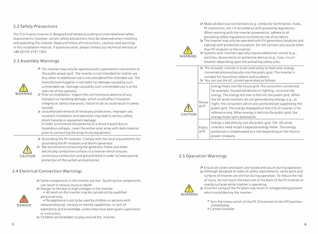
Product Description 3
3.1 Inverter overview
Position Description
7 8
A LCD
B LED
C Rs232 & DIP switch for RS485 configuration and External communication accessories power
D AC output
E RS 485
F DRM PORT(Only for Australia)
G DC switch
H* PV input terminals
I Series Number
J Type label
* 3000-6000TL3-S 7000-11000TL3-S & 12000TL3 2 pairs,12000-15000TL3-S 3 pairs.
&
All operations regarding transport, installation and start-up,
including maintenance must be operated by qualified, trained
personnel and in compliance with all prevailing codes and
regulations.Anytime the inverter has been disconnected from the power
network, use extreme caution as some components can retain
charge sufficient to create a shock hazard; to minimize occurrence
of such conditions, comply with all corresponding safety symbols
and markings present on the unit and in this manual.In special cases, there may still be interference for the specified
application area despite maintaining standardized emission limit
values (e.g. when sensitive equipment is located at the setup
location or when the setup location is near radio or television
receivers).In this case, the operator is obliged to take proper action
to rectify the situation.Possible damage to health as a result of the effects of radiation! Do not stay closer than 20 cm to the inverter for any length of
time.
CAUTION
Symbol Explanation
2.6 Symbols on the inverter
Electrical voltage!
Risk of burns!
Point of connection for grounding protection.
Direct Current (DC)
Alternating Current (AC)
CE mark.The inverter complies with the requirements of the applicable EC
guidelines.
Operation after 5 minutes
EU waste electrical and electronic equipment (WEEE) label
Read the manual

9 10
The inverter is thoroughly tested and inspected strictly before delivery. Our inverters leave
our factory in proper electrical and mechanical condition. Special packaging ensures safe
and careful transportation. However, transport damage may still occur. The shipping
company is responsible in such cases. Thoroughly inspect the inverter upon delivery.
Immediately notify the responsible shipping company if you discover any damage to the
packaging which indicates that the inverter may have been damaged or if you discover
any visible damage to the inverter. We will be glad to assist you, if required. When
transporting the inverter, the original or equivalent packaging should to be used, and the
maximum layers for original carton is four, as this ensures safe transport.
3.4 Transportation
3.5 Storage of Inverter
If you want to storage the inverter in your warehouse, you should choose an
appropriate location to store the inverter.The unit must be stored in original package and desiccant must be left in the
package.The storage temperature should be always between -25℃and +60℃. And the
storage relative humidity should be always between 0 and 95%.If there are lots of inverters need to be stored, the maximum layers for original
carton is four.After long term storage, local installer or service department of manufacturer
should perform a comprehensive test before installation
Information
After long term storage, the Real Time Clock of the inverter
maybe not correct, it will cause the Energy produced today
(E_day) error, you need to set the time and date, refer to 6.3.5
setting inverter time and date.
3.6 The advantage of inverter
The features of inverter are below:
Dual independent MPP trackers
Integrated DC disconnect switch
RS485/Wifi /RF/GPRS
Wide PV voltage range:160V~1000/1100V
The maximum efficiency is 98.3%
IP65 environmental protection
Easy to install
Symbol Description Explanation
Tap symbol Indicates display operation (see Section 6).
Inverter state symbol
Green/constant
Red/constant
Red/flashing
Operation
Fault
Software update
3.2 Type label
The type labels provide a unique identification of the inverter (The
type of product, Device-specific characteristics, Certificates and
approvals). The type labels are on the right-hand side of the
enclosure.The Certificate Number is just for SAA.
Symbol on the inverter
******
XXX
XXX
3.3 Size and weight
A(mm) B(mm) C(mm) D(mm) Weight(kg)
3000-6000 TL3-S
7000-110000 TL3-S
12000-150000 TL3-S
393
393
393
480
480
480
200
200
200
473
473
473
21.2
22
23.5

Unpacking4
Before opening the packing box of UE series inverter, please note that whether there
are any visible external damages.
Once open the packing box, please check the delivery for completeness and for any
visible external damages of the inverter. If there are anything damaged or missing,
please contact your dealer. Complete delivery should contain as follows.
Item Number Description
Information
Though the packaging box of TL3-S is durable, please treat the
packing box gently and avoid dispose the packing box.11 12
A 1 Inverter
B 1 Quick installation guide
C 3 Cable gland for AC connection
D 4 M4 cross recessed countersunk head screws
E 1 Rs485 terminals
F 4 Expansion bolt
G 5/1 Cord End Terminal/AC connector
H
I*
1
2/3
RJ 45 PLUG Only for Australia( )
PV connectors
-- 1 User manual (not show in the picture)
Installation 5
5.1 Safety instruction
Danger to life due to fire or explosion Despite careful construction, electrical devices can cause fires.Do not install the inverter on easily flammable materials and where
flammable materials are stored.
Risk of burns due to hot enclosure partsMount the inverter in such a way that it cannot be touched
inadvertently.
Possible damage to health as a result of the effects of radiation!In special cases, there may still be interference for the specified application
area despite maintaining standardized emission limit values (e.g. when
sensitive equipment is located at the setup location or when the setup
location is near radio or television receivers).In this case, the operator is
obliged to take proper action to rectify the situation.Never install the inverter near the sensitive equipment(e.g. Radios,
telephone, television, etc)Do not stay closer than 20 cm to the inverter for any length of time unless it
is absolutely necessary.We assumes no responsibility for compliance to EMC regulations for the
complete system.
All electrical installations shall be done in accordance with the local and
national electrical codes. Do not remove the casing. Inverter contains no
user serviceable parts. Refer servicing to qualified service personnel. All
wiring and electrical installation should be conducted by a qualified
service personnel.Carefully remove the unit from its packaging and inspect for external
damage. If you find any imperfections, please contact your local dealer.Be sure that the inverters connect to the ground in order to protect
property and personal safety.The inverter must only be operated with PV generator. Do not connect
any other source to it.Both AC and DC voltage sources are terminated inside the PV Inverter.
Please disconnect these circuits before servicing.This unit is designed to feed power to the public power grid (utility) only.
Do not connect this unit to an AC source or generator. Connecting
Inverter to external devices could result in serious damage to your
equipment.
* 3000-11000TL3-S & 12000TL3-S 2 Pairs* 12000TL3-S & 15000TL3-S 3 Pairs
A B
C D E F G H I

5.2 Selecting the Installation Location
5.2.1 This is guidance for installer to choose a suitable installation
location, to avoid potential damages to device and operators.
1) The wall selected to install the inverter must be strong and firm enough to support and bear the weight of the inverter for a long period time. 2) The location selected must be suitable for inverters' dimension. (Refer to 3.3 Dimensions and Fig.5.2 Required Clearances) 3) Do not install the inverter on structures constructed of flammable or thermo labile materials. 4) Never install the inverter in environment of little or no air flow, nor dust environment. 5) The Ingress Protection rate is IP65 which means the inverter can be installed outdoors and indoors. 6) Do not expose the inverter to direct sunlight, in order to avoid the power and efficiency derating caused by excessive heating. 7) The ambient temperature of the inverter should be -25℃~+60℃.
8) The installation location must be freely and safely to get at all times. 9) Vertically installation and make sure the connection of inverter must be downwards. Never install horizontal and avoids forward and sideways tilt.( Refer to drawings below)
13 14
When a photovoltaic panel is exposed to light, it generates a DC voltage.
When connected to this equipment, a photovoltaic panel will charge the
DC link capacitors. Energy stored in this equipment's DC link capacitors presents a risk of
electric shock. Even after the unit is disconnected from the grid and
photovoltaic panels, high voltages may still exist inside the PV-Inverter.
Do not remove the casing until at least 5 minutes after disconnecting all
power sources.Although designed to meet all safety requirements, some parts and
surfaces of Inverter are still hot during operation. To reduce the risk of
injury, do not touch the heat sink at the back of the PV-Inverter or nearby
surfaces while Inverter is operating.
Fig5.1
11) Do not install the inverter near television antenna or any other antennas and antenna cables. 12) Do not install the inverter in living area, the noise caused by the machine may affect on daily life.13) For security reasons, don't install the inverter in place where the children can reach.
10) Notice the minimum clearances of the inverter. (Refer to 3.3 Dimensions and Fig.5.2 Required Clearances).
Fig5.2
5.3 Installation guide
5.3.1 Mounting Expansion Bolt
DANGER
In order to avoid electrical shock or other injury, inspect existing
electronic or plumbing installations before drilling holes.
To mount the inverter on the wall, we should mount expansion bolt to the
wall firmly first.

Hint: Data units in mmSteps:
Drill four holes for expansion bolt use the Fix Hole Paper as template.
Fix the mounting expansion bolt on the wall as the figures shown below, combine
four expansion bolt with four M6 nuts. Refer to Fig 5.4.
Fig5.3
15 16Fig5.4
5.3.2 Mounting Inverter
WARNING
Falling equipment can cause serious or even fatal injury, never
mount the inverter on the bracket unless you are sure that the
mounting frame is really firmly mounted on the wall after carefully
checking.
After expansion bolt is firmly mounted on the wall, then mount the inverter on
expansion bolt. Rise up the inverter a little higher than expansion bolt. Considering the weight of inverter, you need to hang on the inverter. During the process please maintain the balance of the TL3-S. Hang the inverter on the expansion bolt. After confirming the inverter is stuck on expansion bolt, fasten four M6 screws. Refer to Fig 5.5.
Fig5.5
Connection of a second protective conductorIn some installation countries, a second protective conductor is required to
prevent a touch current inthe event of a malfunction in the original protective conductor.For installation countries falling within the scope of validity of the IEC standard
62109, you must installthe protective conductor on the AC terminal with a conductor cross-section of at
least 10 mm²Cu.Or Install a second protective conductor on the earth terminal with the same cross-
section as the original protective conductor on the AC terminal. This prevents touch current if the
original protective conductor fails.
Installation Guide
1.Please make sure that the thickness of the wall for inverter installation
is more than 60mm ;2.
3.
4.
Please place the bitmap horizontally on the wall and confirm the level
by level;
Please mark the holes in the 4 mounting holes of hole pattern;
Drill a hole with a depth of 55mm at the mark with a drill of φ8mm;
5.
6.Please hang the inverter on the expansion bolt and tighten the nut
with a wrench.
Please expand the bolt with a hammer into the hole in the wall and
install the nut(including elastic flat pad), do not tighten the nut.
20
0m
m(
7.
87
inch)
446mm(17.56inch)

17 18
5.3.3 Installation layout
Information
Avoid exposing inverter to direct sunlight, rain or snow to extend
the inverter service life despite the IP65 protection degree. Exposure
to the sunlight may cause additional internal heating which will
cause power derating.
More than one inverter need to be installed, the dimensions below should be
considered.
Fig5.6
Fig5.7
Fig 5.8
Recommend awning installation, the purpose is to extend the inverter service life and
reduce the power derating of the inverter. The dimension of the awning, refer to Fig
5.9.
Fig 5.9

19 20
5.4 Electrical Connections
5.4.1 Safety
DANGER
Danger to life due to lethal voltages! High voltages which may cause electric shocks are present in
the conductive parts of the inverter. Prior to performing any
work on the inverter, disconnect the inverter on the AC and
DC sides
WARNING
Danger of damage to electronic components due to
electrostatic discharge.
Take appropriate ESD precautions when replacing and
installing the inverter.
5.4.2 Wiring AC Output
Conditions for the AC ConnectionYou must comply with the connection requirements of your utility operator.All usages must comply with the regulations.Residual-current protective deviceThe inverter is equipped with an integrated universal residual-current monitoring unit. If the network operator stipulates a residual-current protective device, you must use a
residual-current protective device that triggers in the event of a residual-current of
300 mA or more.
Load disconnection unitYou must install a separate three-phase miniature circuit-breaker or other load
disconnection unit for each inverter in order to ensure that the inverter can be safely
disconnected under load. Measure the public grid voltage and frequency (Voltage: 400Vac; Frequency: 50Hz/60Hz; 3-Phase); Open the breaker between the PV inverter and utility; Specification of AC breaker:
Cable requirements:
1. The AC side terminals of the inverter are like the following figure,Fig. 6a, it is clear to confirm that 'L1, L2, L3' represents three live line output, "N" represents neutral line and is grounding line.2. The five cables should be put through the protection shell, as Fig. 6 b, crimp five standard cables with Cord End Terminal. Tighten all screws.Refer to Fig. 6c.3. Fasten the protection shell onto the bottom of the inverter, make sure the four screws are tightened, the completed appearance is like the below figure Fig. 6d.
Connection to the AC side terminal
a) b)
c) d)
Fig 6
5.4.3 Wiring DC Input
Danger to life due to lethal voltages! Before connecting the PV array, ensure that the DC switch and AC
breaker are disconnect from the inverter. NEVER connect or
disconnect the DC connectors under load.DANGER
5000-7000TL3-S 16A/400V8000TL3-S 20A/400V
9000-12000TL3-S 25A/400V15000TL3-S
3000-4000TL3-S
32A/400V
10A/400V
Outside diameter of cabel(mm)
AWG8
AWG10
AWG12
AWG14
ConductorCross section
38m
3000TL3-S4000TL3-S
5000TL3-S6000TL3-S
8000TL3-S
9000TL3-S
10000TL3-S
11000TL3-S
12000TL3-S13000TL3-S15000TL3-S
40m 31.5m
Max. cable length(m)
18-25
28m 23m25m
40m
17m60m
64m 55m 44.5m 36.5m 27m
54m/
/
/ / / /
/ / / /
///
/

21 22
WARNING
Improper operation during the wiring process can cause fatal injury to
operator or unrecoverable damage to the inverter. Only qualified
personnel can perform the wiring work.
Risk of damage to the inverter. If the voltage of the PV modules exceeds the maximum input voltage of
the inverter, it can be destroyed by the overvoltage. This will void all
warranty claims.Do not connect strings to the inverter that have an open-circuit voltage
greater than the maximum input voltage of the inverter.
To reduce the risk of electric shock, avoid touching the live components
and treat the terminals carefully.
Information
Please use the same brand male and female PV connectors.Under any conditions the total circuit current should never exceed the
Max. Current.
NOTICE
Excessive voltages can destroy the measuring deviceOnly use measuring devices with a DC input voltage range up to at least
1000 Vdc.
1 Check the connection cables of the PV modules for correct polarity and make sure that the maximum input voltage of the inverter is not exceeded. 2 The diagram drawing of DC side is shown as below, notice that the connectors are in paired (male and female connectors).
Fig 6.1
F i g 6 . 2

5.4.4 Grounding
AC Grounding
The TL3-S series inverter must be connected to the AC grounding conductor of the
power distribution grid via the ground terminal (PE).
PV Grounding
The grounding conductor in the framework of the PV array must be connected to the
PV grounding conductor and the DC grounding conductor. The cross-section of the
grounding conductor corresponds to the cross-section of the largest conductor in the
DC system.
DC Grounding Conductor
A DC grounding conductor may be required by the Authority Having Jurisdiction
(AHJ). Use the terminal block for the PV grounding conductor and DC grounding
conductor.
5 In order to seal the inverter, all unneeded DC inputs must be closed with sealing
plugs:Cable requirements:
Model Diameter(mm) Area(mm²) AWG
3000-15000TL3-S 1.63-2.05 2.0-4 14-12
3 Check the assembled DC connectors for correct polarity and connect them to the inverter.4 The maximum string currents are varying from different inverter types.
Model Max.current
7000TL3-S
3000-6000TL3-S
8000-9000TL3-S
10000-11000TL3-S
12000TL3
12000-15000TL3-S
11.5A/11.5A
11A/11A
11.5A/11.5A
13A/13A
11.5A/11.5A
20A/10A
Ground kit
If PV modules of the PV system require POSITIVE or NEGATIVE to connect to
GROUND, the output of inverter should connect to grid with an isolating
transformer. The connection method is below:
N of transformer should not be connected to PE.
Inverter
L1
L2
L3
N
PE
5.5 Grid Type
5.5.1 Common grid type
Based on the local GRID standards, it may select different connection types. In the
following you will find an overview of the most common type of grid structure.
Transformer
L1
L2
L3
PEN
PE
TL3
TN-CTransformer
L1
L2
L3
N
PE
TL3
TN-STransformer
L1
L2
L3
N
PE
TL3
TN-C-S
Transformer
L1
L2
L3
N
PE
TL3
TTTransformer
L1
L2
L3
PE
TL3
IT
5.5.2 Compatibility Table
Grid type TN-C grid TN-S grid TN-C-S grid TT grid IT grid
Grid type
3000-15000TL3-S
yes(N and PE of inverter both should connect to PEN of grid.)
yes yes yes,if UN-PE < 30V
yes,if UN-PE < 30V
23 24

25 26
6 Commissioning 6.1 Commission the Inverter
1) Remove all covers from the PV array.2) Check the PV and AC voltage.3) Plug in the PV input.4) Turn the DC Disconnect to position "I".5) If the inverter is connected with PV panel arrays and the input voltage is higher than 160Vdc, while the AC grid is not connected yet, LCD will display messages in order as below: Company info Basic info State info The LCD will display “ AC V outrange “at State info and the LED turns red. Please check all information on the LCD, operate by knocks you will see the different parameters. Single knock to Light the backlight State info (single knock) Input info (single knock) Output info
6) Turn on the AC breaker between inverter and grid, the
system will operate automatically.7) Under normal operating conditions, the LCD displays
'Power: xx.xx Kw' at State info, this is the power feed into
grid. The LED turns green.8) Check the time and date of inverter as follow:Single knock to Light the backlight State info (Thrice
knock) Inverter info (single knock) System Time(double
knock), if they are not correct, please set them, refer to
6.3.5 setting inverter time and date.9) Finish commissioning.
6.2 Operation Modes
Normal Mode
In this mode, the inverter works normally and LED turns green. Whenever the DC voltage is higher than 200Vdc, inverter converts power to grid Whenever the DC voltage is lower than 180Vdc, the inverter will work in waiting status and attempt to connect the grid. In waiting state the inverter consumes just power generated by the PV panel to monitor the internal system. Notes: The inverter starts up automatically when DC power from the PV panel is sufficient.
Fault Mode
The internal intelligent controller can continuously monitor and adjust the system
status. If inverter finds any unexpected conditions such as system fault and inverter
fault, the fault information will be displayed on the LCD. In fault mode the LED turns
red.Notes: a) Detailed fault information refers to Chapter 9 Trouble shooting. b) When PV Isolation error occurred in SAA safety standard, the buzzer will give an alarm every fifteen seconds.
Derating mode
When AC frequency is higher than 50.3Hz(settable), the inverter will derate its
output power according to the rule. When user set the output limit command to the inverter, the inverter will also limit
the output according to the setting.In this derating mode, the LCD will show “DERATING”.
6.3 Country Setting and LCD Display
In the lower right corner of inverter there is the LCD display. We can check inverter
running state, historical generation data, etc, on the LCD screen. Items displayed can
be changed by knock; you can also change some inverter parameters by knock.
6.3.1 Location of the country setting DIP switch
The DIP switch is located on the left of the RS232 interface at the bottom of the
inverter, as the figure below.
To reduce the risk of electric shock, before selecting country, please turn
off DC input and AC grid, than unscrew the dam-board of the DIP switch
by appropriate tool.WARNING
Shutdown Mode
Inverters automatically stop running during periods of little or no sunlight. In
shutdown mode the inverters take no power from the grid and panel, and the LCD
and LED turns off.Notes: If the PV string DC voltage is too low, the inverter will also turn to Shutdown
Mode.
Country setting DIP switch

27 28
The internal structure of the DIP switch is as the following figure:
6.3.2 DIP switch option corresponding to the country
DANGER
When you setting the DIP, you must turn off the AC breaker and DC
breaker.
Information
After setting the DIP, please power on the inverter and check the
model display. If the last character of the model name is
corresponding to the country safety standard as the above table, it
means your setting is successful.You should change the time displayed on the LCD of inverter to
your local time after inverter starts up.If the country is set incorrectly, please shut down the inverter
and set again.
When the cables of AC side and DC side are all well connected, before
commissioning, the country safety standard must be selected by the DIP switch. The DIP switch is composed of four-digit binary number PINS. The different
combination of the four PINS can represent different inverter's model, which is
corresponding to the local grid standard. Each small white PIN has two statuses,
when set upward to 'ON', its value turns to '1', when set downward, its value turns
to '0'. Concerning the matching of the PIN status and the country safety standard,
please refer to the table below:
Switch to country table 6.3.1
DIP switch status Country Model display
VDE 0126 GTXXXXXXX1
G59-3 GTXXXXXXX2
4 23 1ON5
4 23 1ON5
AS4777-Australia GT0XXXXXX3
CEI 0-21 GT0XXXXXX4
SP1699/Spain GT0XXXXXX5
Greece GT0XXXXXX6
VDE-AR-N4105 GT0XXXXXX7
G83-2 GT0XXXXXX8
EN50438-Ireland GT0XXXXXX9
CQC GT0XXXXXXA
EN50438-Default GT0XXXXXXB
4 23 1ON5
4 23 1ON5
4 23 1ON5
4 23 1ON5
4 23 1ON5
4 23 1ON5
4 23 1ON5
4 23 1ON5
4 23 1ON5

29 30
IEC61727&IEC62116 GT0XXXXXXC
Belgium GT0XXXXXXD
Thailand MEA GT0XXXXXXE
4 23 1ON5
4 23 1ON5
4 23 1ON5
4 23 1ON5 Thailand PEA GT0XXXXXXF
4 23 1ON5
4 23 1ON5
4 23 1ON5
4 23 1ON5
4 23 1ON5
AS4777_Newzealand GT1XXXXXX0
Reserved GT1XXXXXX1
India GT1XXXXXX2
EN50438_Demark GT1XXXXXX3
EN50438_Sweden GT1XXXXXX4
EN50438_Norway GT1XXXXXX5
VFR2013 GT1XXXXXX6
VFR2014 GT1XXXXXX7
Reserved GT1XXXXXX8
Reserved GT1XXXXXX9
4 23 1ON5
4 23 1ON5
4 23 1ON5
4 23 1ON5
4 23 1ON5

31 32
6.3.3 Display interface
Overall display interface introduction
Th
ree
Double Double
Once
Double
Set Date/Time Date:2012/04/05
Time:14:20:38
Once
Double
AC V Control: Enable
Model: PV0000F161
FW Version:
DH 1.0–DH 0.0
1 AC F Outrange
Time:14:20:30
FW Version:
Build:dhaa-0101
Date:2012/04/05
Time: 14:20:38
Once
Once
Once
Once
Once
Once
Double
Double
Double Once
Once
Double Once Once
Double Once Once
Once
Double Once Once
Once Once
Once
Once
Once
AC VA/Watt: VA W
Connect OK
AC V Control :
Disable/Enable
Set Com Address 003
Set Com Address 003
AC V Control : Disable
Input Word:123 000
Input Word:123 123
Growatt PV Inverter
SerNo: PR34200090
Setting
Model: PVBC00F161
FW Version:
DH 1.0–DH 0.0
Connect in: s
Etoday: 50 .2 Kwh
Power info
Input Info
Eall: 2000 Kwh
Etoday: 50 .2 Kwh
PV1 Volt: V Power: W
PV2 Volt: VPower: W
Output InfoGridFreq:50.0Hz
Set Info
Inverter infoSerNo: PR34200090
COM Addr: 003
Power Rate: 20%P_Factor: 1.0
AC VA/Watt: VA W
1. Once: Next page
2. Double:Enter 3.Three: Enter the setting4.Four: Back to cycle display interface
AC Error Record1 AC F Outrange
Date:2016/04/06
1 AC F Outrange
AC F:48Hz
2 AC V Outrange
AC V:20.2V
2 AC V Outrange
Date:2016/04/06
2 AC V Outrange
Time:14:20:30
Eall: 2000 Kwh
AC Volt A/B/C 230V/230V/230V
Set Language Set Language English
Once
On
ce
Once
Double
Fig6.3 Overall display interface
Power on display
After inverter restarts, the background light will last for 2 seconds. You can check the
inverter series number, model, firmware version. Refer Fig6.3.1.
Growatt PV Inverter
SerNo: PR34200090
Model: PVBC00F161
FW Version:
DH 1.0–DH 0.0
Fig6.3.1Power on display
6.3.4 Operate by knock
Knock type and definition
Table 6.3.2 Knock definition list
Knock type Definition
Single knock Down
Double knock Enter
Knock four times Back to cycle display interface
The inverter can support four kinds of knock: single knock, double knock, third
Knock, Knock four times. Each kind of knock has different function. Refer to
specified definition in Table 6.3.2.
Three knock Make sure setting
Light backlight and single knock to check running information
Before light the backlight, the four types of knock functions are the same, which is
just lighting the backlight. Note that the background lighting will automatically turn
off if there is no knock detected in 10 seconds.
During cloudy days or in the area of low light, it’s inconvenient for users to check
inverter running information such as status, input data, output data, energy
generated. In this case user can light the backlight and check those data by single
knock, a single knock will switch LCD screen to a following interface.

6.3.5 Data checking and parameters setting
Cycle display
If you do not knock the enclosure lid, LCD display following information cycle by
cycle. Refer Fig 6.3.3.
Fig 6.3.3 Cycle display
Parameters setting
AC VA/Watt: VA W
Etoday: 50 .2 Kwh
Eall: 2000 Kwh
Fig 6.3.4 is the setting information. Single knock, the Text will display the setting.
Double knock, the Text will display”input123: 000”. Single knock to go back Setting
page. Double knock the enclosure lid ready to input password. Single knock to
change value of first, double knock enter into next position. Konck three times when
the bit was “123”, it will go into Setting options.
Input Word:123 000
Input Word:123 000
Double
Input Word:123 100
Input Word:123 100
Input Word:123 110
Once
Once
Double
Input Word:123 120
On
ce
Input Word:123 120
Double
Input Word:123 121
Once
Input Word:123 122
Once
Input Word:123123
Once
Setting
Double
Three
Input OK
33 34
Fig 6.3.4 setting second level menu and its sub-menus
Set Com Address 001
Set Language
Set Date/Time
AC V Control :
Disable/Enable
Once
Once
Once
Setting
Three
Set LanguageEnglish
Double
AC V Control :
Disable
Double
Double Date:2012/04/05
Time: 14:20:38
Setting language
To change inverter’s displaying language, please select Setting->Set language, then
LCD screen will display current language type, single knock to change current
language, knock three times will save changes and displays “Set OK! Current
Language English” Refer Fig 6.3.5. Knock four times to exit setting.
Set Language
Set Language English
Set Language xxxx
Once
Three
Set OK
Fig 6.3.5 setting language
Please note in order to prevent disoperation, system language won’t be change in
second level menu “Set language”, but it will be only if user saves save the choice by
knock three times and LCD displays “Set OK!”
Setting inverter’s COM addressWhen communicating with monitoring software or device, the software or device
may regard inverter’s COM address as communication address (Also may use
inverter’s serial number as communication address).The COM address could be
assigned. The second level menu “Set COM Addr” of setting is to set inverter’s COM
address.

35 36
Setting COM addressInput password->Setting language->Set COM addr-> is the current address of
inverter.”Double knock the enclosure lid ready to input COM addr. Single knock to
change COM Addr. Knock three times to save COM Addr. Refer Fig 6.3.6. Knock four
times to exit setting.
Set Com Address 001
Set Com Address 001
Set Com Address
012
Set Com Address
002
Set Com Address 002
Set Com Address
012
Set Com Address
112
Set OK
Double
Once
Double
Once
Double
Once
Three
Fig 6.3.6 current COM Addr
Setting inverter time and dateInverter provides a system clock; user must set the system time after installation, as
the historical statistic data for a period were based on the clock. User can set the
following time parameters: year, month, day, hour, minute.
Input password->Setting-> 2017/03/27 00:38 ->is the current time. Double knock to
go into setting. Single knock to change time. Konck three times to save time. Knock
four times to exit setting. Refer Fig 6.3.7.
Date: 2012/04/05
Time: 14:20:38
Date: 2013/04/05
Time: 14:20:38
Date: 2013/04/05
Time: 14:20:38
Date: 2013/05/05
Time: 14:20:38
Set Date/Time Date: 2013/05/06
Time: 14:20:38
Date: 2013/05/06
Time: 14:20:38
Date: 2013/05/06
Time: 15:20:38
Date: 2013/05/06
Time: 15:20:38
Date: 2013/05/06
Time: 15:21:38
Set OK
Double
Once
Double
Once
Double
Once
Double
Once
Double
Once
Three
Date: 2013/05/05
Time: 14:20:38
Fig 6.3.7 inverter date and time
6.4 Double MPPT of the TL3-S
The TL3-S includes dual input section to process two strings with independent MPPT,
high speed and precise MPPT algorithm for real-time power tracking and energy
harvesting, as well as transformerless operation for high performance, the max
conversion efficiency is up to 98.3%. The wide input voltage range makes the
inverter suitable to low power operation as well as the high power operation.
As the weather influence and the location of two MPPT PV arrays different, the
power of the MPPT A inputs is different from the power inputs of the MPPT B at the
same time, the TL3-S works at a non-symmetrical input status. But the MPPT
algorithm of the inverter makes it tracking the maximum power point of every MPPT
channel to improve the energy utilization of the PV arrays.
6.5 Communication
6.5.1 Using shinebus to set the information of the inverter or update firmware
About the software of shinebus and the usage of it please download from the web:
www.growatt.com

37 38
6.5.2 Monitor the inverters
The inverter provides RS485 interface and RS232 interface to communicate with
remote PC or logger. User can monitor the inverter status via the following types of
communication systems.
You can update firmware via RS232 or Rs485
The connecting diagram as follow:
Active power control with a ripple control signal receiver
Through RS485 interface-RS485-232 /RS232 converter-PC.
Information
If you plan to update firmware via RS485, please disconnect the
monitor device.
Through RS485 interface-Data logger-PC.
Plan A:
Through RS232 interface- wireless module-Data logger-Internalet.

39 40
Plan B
Information
When three phase inverter and single-phase inverter shared a RS485
communication line, the total length of which does not exceed 1km
and device number should not be more than 32.
6.5.3 RS485 cable connection
Rs485 cable connection
Pin1------- TR-(B)
Pin2------- Shielding layer or no connection
Definitions of RS485 PLUG (standard) as follows:
Pin1------- TR-(B)
Pin2------- Shielding layer or no connection
Pin3------- TR+(A)
Pin3------- TR+(A)
1. Please loosen four screws, take down the RS485 waterproof cover from inverter. If
you don’t choose RS485 as communication method, keep it on the inverter.

41 42
2. Slightly loosen the swivel nut, remove the filler-plug from the M16 cable gland.
Information
Pull cables outwards to confirm whether they are installed firmly
3. Make the cable through the hole of cable gland and put the cable into the Rs485
terminals, fix all cables with screwdriver (‘1’to’ T/R-(B)’, ‘3’to’ T/R+(A)’, ‘2’ to the
shielding layer or no connection). The type of cable is recommended as STP, FTP,ASTP.
4. Plug in two terminals. Cover the fix board.
Information
Tighten 4 pcs screws first, then tighten cable gland.
5. Tighten 4pcs screws and cable gland.
Note:
1) As to the connection between inverters, please refer to the following figure.
2) As to the connection between inverter and ShineWebBox, please refer to the
following figure.
6.5.4 Inverter demand response modes (DRMs,only for Australia)
This series inverter has the function of demand response modes, We use RJ45 socket
as inverter DRED connection.
6.5.4.1 Definitions of RJ45 socket pins as follows:

43 44
Pin1------- DRM5
Pin2------- DRM6
Pin3------- DRM7
Pin5------- RefGen
Pin6------- COM/DRM0
Pin4------- DRM8
Pin7------- NC
Pin8------- NC
6.5.4.2 Definitions of RJ45 plug pins as follows
No. of RJ45 plug
1
2
4
5
3
6
7
white and orange
orange
blue
white and Blue
white and green
green
white and brown
Color of the wires
8 brown
6.5.4.3 Method of asserting demand response modes
MODE
DRM0
DRM5
DRM7
DRM8
DRM6
5
1
3
4
2
Rj45 socket Asserted by shorting pins
Operate the disconnection device
Do not generate power
Do not generate at more than 75% of rated power AND Sink reactive power if capable
Increase power generation (subject to constraints from other active DRMs)
Do not generate at more than 50% of rated power
Requirement
8
5
5
5
5
Start-Up and shut down the inverter 7
7.1 Start-Up the inverter
1.Turn on the AC grid breaker;
2.Turn on the DC switch of the inverter, and the inverter will start automatically when
the input voltage is higher than 160V.
7.2 Shut down the Inverter
1.Turn off the AC grid breaker;
2.Turn off the DC switch of the inverter.
3.Check the inverter operating status.
4.Until the display of LCD goes out, the inverter is shut down.
Once the output power is derating because of too high warming, some tips can help
you solve such problems:
The air grills are clogged. To clean the air grills or heat sink.
Ventilation of installation location is poor. Choose appropriate installation
location before mounting.
8.1 Cleaning the Inverter
If the inverter is dirty, turn-off the AC breaker and DC switch, waiting the inverter
shut down, then clean the enclosure lid and the display using only a wet cloth. Do not
use any cleaning agents (e.g. solvents or abrasives).
8.2 Checking the DC Disconnect
8 Maintenance and Cleaning
Check for externally visible damage and discoloration of the DC Disconnect and the
cables at regular intervals. If there is any visible damage to the DC Disconnect, or
visible discoloration or damage to the cables, contact the installer.
Once a year, turn the rotary switch of the DC Disconnect from the “On” position
to the “Off” position 5 times in succession. This cleans the contacts of the rotary
switch and prolongs the electrical endurance of the DC Disconnect.

45 46
9 Trouble shooting
Our quality control program assures that every inverter is manufactured to accurate
specifications and is thoroughly tested before leaving our factory. If you have
difficulty in the operation of your inverter, please read through the following
information to correct the problem.
9.1 Error Messages displayed on LCD
An error message will be displayed on the LCD screen when a fault occurs. The faults
consist of system fault and inverter fault.
You may be advised to contact manufacturer in some situation, please provide the
following information.
Information concerning the inverter:
Serial number
Model number
Error message on LCD
Short description of the problem
Grid voltage
DC input voltage
Can you reproduce the failure? If yes, how?
Has this problem occurred in the past?
What was the ambient condition when the problem occurred?
Manufacturer name and model number of the PV panel
Output power of the panel
Voc of the panel
Vmp of the panel
Imp of the panel
Number of panels in each string
Information concerning the PV panels:
If it is necessary to replace the unit, please ship it in the original box.
9.2 System fault
System fault (system faults are mainly caused by system instead of inverter, please
check the items as instructed below before replacing inverter).
Error message Description Suggestion
Error: 124 No AC connection Check AC wiring.
Check the status of AC breaker
PV Isolation Low Insulation problem 1. Check if panel enclosure ground
properly.
2. Check if inverter ground properly.
3. Check if the DC breaker gets wet.
4. Check the impedance of PV (+) & PV (-)
between ground (must be more than 50
KΩ or 1000 KΩ (VDE 0126)). If the error
message is displayed despite the above
checking passed, contact Growatt.
Residual I High
Error: 126
Leakage current too
high
1.Restart the invert.
2. If error message still exists, contact
Growatt.
PV Voltage High
Error: 128
The DC input voltage is
exceeding the maximum
tolerable value.
1. Disconnect the DC switch immediately.
2. Check the voltage of each PV string with
multimerter.
3. If the voltage of PV string is lower than
1000V, contact Growatt.
Error: 125
Auto Test Failed Auto test didn’t pass. Restart inverter, repeat Auto Test, if
problem still exist, contact Growatt.
AC V Outrange
Error: 129
Utility grid voltage is out
of permissible range.
Please switch off DC switch.
Check AC wiring, especially neutral and
ground wire.
Check grid voltage is complied with local
grid standard. Restart inverter, if problem
still exist, Contact Growatt.
AC F Outrange
Error: 130
Utility grid frequency out
of permissible range.
Please switch off DC switch.
Check AC wiring, especially neutral and
ground wire.
Check grid frequency is complied with local
grid standard. Restart inverter, if problem
still exist, Contact Growatt.

47 48
9.3 Inverter warning
Warning code Meanings Suggestion
Warning103 Restart the inverter. If the warning still
exist, please contact customer service to
replace the COM board.
Warning 105 Fail to write EEPROM. Restart the inverter. If the warning still
exist, please contact our customer service
to replace the COM board.
9.4 Inverter fault
Error code Meanings Suggestion
Fail to read EEPROM.
Warning104 Uptate the right version firmware.firmware version is not
consistent.
Error: 101 Restart inverter, if problem still exist,
update the firmware;
Change control board or COM
board, if problem still exist, contact
Growatt.
Communication board has not
received data from control board
for 10 seconds.
Error: 117 Relay fault. Restart inverter, if problem still exist,
Contact Growatt.
Error: 107 Restart inverter, if problem still exist,
Contact Growatt.
The AC voltage sampled by the
main MCU and redundant MCU is
not the same.
Error: 116 Bus sample fault Restart inverter, if problem still exist,
Contact Growatt.
Warning 109
Warning 108 PV 1 or PV2 Circuit short
PV 1 or PV2 boost broken
Check the PV panel polarity.
Restart the inverter. If the warning still
exist, please contact Growatt customer
service to replace the POWER board.
Restart the inverter. If the warning still
exist, please contact Growatt customer
service to replace the power board.
Error: 103 EEPROM fault. Restart inverter, if problem still exist,
Contact Growatt.
Error: 121 Control board has not received
data from Communication board
for 5S.
Restart inverter, if problem still exist,
update the firmware;
Change control board or COM
board, if problem still exist, contact
Growatt.
Error: 120 Current unbalance Restart inverter, if problem still exist,
change power board, or contact
Growatt.
Error: 122 Bus over voltage Restart inverter, if problem still exist,
Contact Growatt.
Error: 119 GFCI fault. Restart inverter, if problem still exist,
Contact Growatt.
Error: 127 Output High DCI Restart inverter, if problem still exist,
Contact Growatt.
Error: 131 Over Temperature If the ambient temperature of
inverter is lower than 60°C, restart
inverter, if error message still exists,
contact Growatt.

49 50
10 Decommissioning
10.1 Dismantling the Inverter
1. Disconnect the inverter as described in section 7.
2. Remove all connection cables from the inverter.
CAUTION
Danger of burn injuries due to hot enclosure parts!
Wait 20 minutes before disassembling until the housing has
cooled down.
3. Screw off all projecting cable glands.
4. Lift the inverter off the bracket and unscrew the bracket screws.
10.2 Packing the Inverter
If possible, always pack the inverter in its original carton and secure it with tension
belts. If it is no longer available, you can also use an equivalent carton. The box must
be capable of being closed completely and made to support both the weight and the
size of the inverter.
10.3 Disposing of the Inverter
Do not dispose of faulty inverters or accessories together
with household waste. Please accordance with the disposal
regulations for electronic waste which apply at the
installation site at that time. Ensure that the old unit and,
where applicable, any accessories are disposed of in a
proper manner.
11 Specification
11.1 Specification of TL3-S
Model 3000TL3-S 4000TL3-S 6000TL3-S 5000TL3-S
Specification
Input data
Max. DC power 3600W 4800W 6000W 7200W
Max. DC voltage 1000V 1000V 1000V 1000V
Start Voltage 140V 140V 140V 140V
PV voltage range 140V-1000V 140V-1000V 140V-1000V 140V-1000V
MPP voltage range/
DC nominal voltage200V-1000V /620V
Max. PV Isc 16A/16A 16A/16A 16A/16A 16A/16A
Number of independent
MPP trackers/strings per
MPP tracker
2/1+1 2/1+1
Full load voltage
range 160V-800V 200V-800V 250V-800V 290V-800V
Max. input current 11A/11A 11A/11A 11A/11A 11A/11A
Backfeed current 0A 0A 0A 0A
Output (AC)
Inrush current <15A <15A <15A <15A
Max output fault
current
Max output overload
protection
Nominal AC voltage
range
AC grid frequency 50/60Hz 50/60Hz 50/60Hz 50/60Hz
AC grid frequency range 44-55Hz/54-65Hz
Nominal AC voltage 230V/400V 230V/400V 230V/400V 230V/400V
Max. output current 4.5A 6.1A 7.6A 9.1A
Rated AC output power 3kW 4kW 5kW 6kW
Max AC apparent power 3kVA 4kVA 5kVA 6kVA
22A 22A 22A 22A
10A 10A 16A 16A
310~476V 310~476V 310~476V 310~476V
2/1+12/1+1

Topology transformerless
Cooling concept Natural convection
Environmental Protection
RatingIP 65
Relative humidity 0...100%
Features
DC connection H4/MC4(opt)
AC connection Screw terminal
Display
Interfaces:
RS232/RS485/GPRS
/RF/Wifi
yes/yes/opt/opt
/opt
Warranty: 5 years
/ 10 yearsyes /opt
Certificates and
approvals
EN61000-6-2,EN61000-6-3,EN61000-3-2,EN61000-3-3,
IEC62109-1,IEC62109-2,CE,VDE0126,NB/T32004-2013
LCD
Self-consumption night <0.5 W
51 52
Efficiency
Max efficiency 98.0% 98.0% 98.0%
Euro-eta 96.7% 96.9% 97.1%
MPPT efficiency 99.5% 99.5% 99.5%
Power factor at rated power 1 1 1 1
Adjustable displacement
power factor
THDi @Full load&THDv<1%
0.8leading - 0.8laging
AC grid connection type
<3% <3% <3% <3%
3W+N+PE 3W+N+PE 3W+N+PE 3W+N+PE
Protection devices
DC reverse polarity
protection
yes yes yes yes
yes
yes
yes
yes
yes
yes
DC switch for each MPPT yes yes yes
Output AC overcurrent
protection yes yes yes
Output AC overvoltage
Protection - Varistor yes yes yes
Ground fault monitoring yes yes yes
Grid monitoring yes yes yes
Integrated all-pole
sensitive
leakage current
monitoring unit
yes yes yes
General Data
Dimensions(W/H/D)
in mm
Weight
Operating
temperature range
–25 °C ... +60 °C
(–13 °F ... +140 °F)
With derating above 45 °C(113 °F)
Noise emission (typical) ≤ 35 dB(A)
480*448*200
21.2kg
Altitude 3000m
98.0%
96.5%
99.5%

Model 7000TL3-S 8000TL3-S 9000TL3-S
Specification
Input data
Max. DC power 8400W 9600W 10800W
Max. DC voltage 1000V 1000V 1000V
Start Voltage 160V 160V 160V
PV voltage range 160V-1000V 160V-1000V 160V-1000V
MPP voltage range/
DC nominal voltage200V-1000V /600V
Max. PV Isc 16A/16A 16A/16A 16A/16A
Number of independent
MPP trackers/strings per
MPP tracker2/1+1
Full load voltage
range 320V-850V 360V-850V 400V-850V
Max. input current 11.5A/11.5A 11.5A/11.5A 11.5A/11.5A
Backfeed current 0A 0A 0A
Output (AC)
Inrush current <15A <15A <15A
Max output fault
current
Max output overload
protection
Nominal AC voltage
range
AC grid frequency 50/60Hz 50/60Hz 50/60Hz
AC grid frequency range 44-55Hz/54-65Hz
Nominal AC voltage 230V/400V 230V/400V 230V/400V
Max. output current 11.7A 13.3A 15A
Rated AC output power 7kW 8kW 9kW
Max AC apparent power 7.7kVA 8.8kVA 9.9kVA
33A 33A 33A
16A 20A 25A
310~476V 310~476V 310~476V
2/1+12/1+1
Efficiency
Max efficiency 98.3% 98.3%
Euro-eta 97.8% 98%
MPPT efficiency 99.5% 99.5%
Power factor at rated power 1 1 1
Adjustable displacement
power factor
THDi @Full load&THDv<1%
0.8leading - 0.8laging
AC grid connection type
<3% <3% <3%
3W+N+PE 3W+N+PE 3W+N+PE
Protection devices
DC reverse polarity
protection
yes yes yes
DC switch for each MPPT yes yes yes
Output AC overcurrent
protection yes yes yes
Output AC overvoltage
Protection - Varistor yes yes yes
Ground fault monitoring yes yes yes
Grid monitoring yes yes yes
Integrated all-pole
sensitive
leakage current
monitoring unit
yes yes yes
General Data
Dimensions(W/H/D)
in mm
Weight
Operating
temperature range
–25 °C ... +60 °C
(–13 °F ... +140 °F)
With derating above 45 °C(113 °F)
Noise emission (typical) ≤ 35 dB(A)
480*448*200
22kg
Altitude 3000m
98.3%
97.5%
99.5%
53 54

Topology transformerless
Cooling concept Natural convection
Environmental Protection
RatingIp65
Relative humidity 0...100%
Features
DC connection H4/MC4(opt)
AC connection Screw terminal
Display
Interfaces:
RS232/RS485/GPRS
/RF/Zigbee/Wifi
yes/yes/opt/opt
/opt/opt
Warranty: 5 years
/ 10 yearsyes /opt
Certificates and
approvals
EN61000-6-2,EN61000-6-3,EN61000-3-2,EN61000-3-3,
IEC62109-1,IEC62109-2,CE,VDE0126,NB/T32004-2013
LCD
Self-consumption night <0.5 W Model 10000TL3-S 11000TL3-S 12000TL3
Specification
Input data
Max. DC power 12000W 14400W 14400W
Max. DC voltage 1000V 1000V 1100V
Start Voltage 160V 160V 160V
PV voltage range 160V-1000V 160V-1000V 160V-1000V
MPP voltage range/
DC nominal voltage200V-1000V /600V
Max. PV Isc 16A/16A 16A/16A 16A/16A
Number of independent
MPP trackers/strings per
MPP tracker2/1+12/1+12/1+1
Full load voltage
range 450V-850V 450V-850V 550V-850V
Max. input current 13A/13A 13A/13A 11.5A/11.5A
Backfeed current 0A 0A 0A
Output (AC)
Inrush current <15A <15A <15A
Max output fault
current
Max output overload
protection
Nominal AC voltage
range
AC grid frequency 50/60Hz 50/60Hz 50/60Hz
AC grid frequency range 44-55Hz/54-65Hz
Nominal AC voltage 230V/400V 230V/400V 230V/400V
Max. output current 16.7A 18.3A 19A
Rated AC output power 10kW 11kW 12kW
Max AC apparent power 11kVA 12.1kVA 13.2kVA
33A 33A 44A
25A 25A 25A
310~476V 310~476V 310~476V
55 56
(note 1)

57 84
Efficiency
Max efficiency 98.3% 98.3%
Euro-eta 98% 97.8%
MPPT efficiency 99.5% 99.5%
Power factor at rated power 1 1 1
Adjustable displacement
power factor
THDi @Full load&THDv<1%
0.8leading - 0.8laging
AC grid connection type
<3% <3% <3%
3W+N+PE 3W+N+PE 3/N/PE
Protection devices
DC reverse polarity
protection
yes yes yes
DC switch for each MPPT yes yes yes
Output AC overcurrent
protection yes yes yes
Output AC overvoltage
Protection - Varistor yes yes yes
Ground fault monitoring yes yes yes
Grid monitoring yes yes yes
Integrated all-pole
sensitive
leakage current
monitoring unit
yes yes yes
General Data
Dimensions(W/H/D)
in mm
Weight
Operating
temperature range
–25 °C ... +60 °C
(–13 °F ... +140 °F)
With derating above 45 °C(113 °F)
Noise emission (typical) ≤ 35 dB(A)
480*448*200
22kg 22kg 23.5kg
Altitude 3000m
98.3%
98%
99.5%
Topology transformerless
Cooling concept Natural convection
Environmental Protection
RatingIp65
Relative humidity 0...100%
Features
DC connection H4/MC4(opt)
AC connection Screw terminal
Display
Interfaces:
RS232/RS485/GPRS
/RF/Zigbee/Wifi
yes/yes/opt/opt
/opt/opt
Warranty: 5 years
/ 10 yearsyes /opt
Certificates and
approvals
EN61000-6-2,EN61000-6-3,EN61000-3-2,EN61000-3-3,
IEC62109-1,IEC62109-2,CE,VDE0126,NB/T32004-2013
LCD
Self-consumption night <0.5 W
Note 1:Max. output current is 15.9A for UK market.of Growatt 10000TL3-S

59 60
Model 12000TL3-S 13000TL3-S 15000TL3-S
Specification
Input data
Max. DC power 14400W 15600W 18000W
Max. DC voltage 1100V 1100V 1100V
Start Voltage 160V 160V 160V
PV voltage range 160V-1000V 160V-1000V 160V-1000V
MPP voltage range/
DC nominal voltage200V-1000V /600V
Max. PV Isc 16A/16A 16A/16A 16A/16A
Number of independent
MPP trackers/strings per
MPP tracker
2/2+1
Full load voltage
range 480V-850V 480V-850V 520V-850V
Max. input current 20A/10A 20A/10A 20A/10A
Backfeed current 0A 0A 0A
Output (AC)
Inrush current <15A <15A <15A
Max output fault
current
Max output overload
protection
Nominal AC voltage
range
AC grid frequency 50/60Hz 50/60Hz 50/60Hz
AC grid frequency range 44-55Hz/54-65Hz
Nominal AC voltage 230V/400V 230V/400V 230V/400V
Max. output current 19A 20.6A 23.8A
Rated AC output power 12kW 13kW 15kW
Max AC apparent power 13.2kVA 14.3kVA 16.5kVA
44A44A 44A
25A 32A 32A
310~476V 310~476V 310~476V
2/2+1 2/2+1
Efficiency
Max efficiency 98.3% 98.3%
Euro-eta 98% 98%
MPPT efficiency 99.5% 99.5%
Power factor at rated power 1 1 1
Adjustable displacement
power factor
THDi @Full load&THDv<1%
0.8leading - 0.8laging
AC grid connection type
<3% <3% <3%
3W+N+PE 3W+N+PE 3W+N+PE
Protection devices
DC reverse polarity
protection
yes yes yes
DC switch for each MPPT yes yes yes
Output AC overcurrent
protection yes yes yes
Output AC overvoltage
Protection - Varistor yes yes yes
Ground fault monitoring yes yes yes
Grid monitoring yes yes yes
Integrated all-pole
sensitive
leakage current
monitoring unit
yes yes yes
General Data
Dimensions(W/H/D)
in mm
Weight
Operating
temperature range
–25 °C ... +60 °C
(–13 °F ... +140 °F)
With derating above 45 °C(113 °F)
Noise emission (typical) ≤ 35 dB(A)
480*448*200
23.5kg
Altitude 3000m
98.3%
98%
99.5%

61 62
Topology transformerless
Cooling concept Natural convection
Environmental Protection
RatingIp65
Relative humidity 0...100%
Features
DC connection H4/MC4(opt)
AC connection Screw terminal
Display
Interfaces:
RS232/RS485/GPRS
/RF/Zigbee/Wifi
yes/yes/opt/opt
/opt/opt
Warranty: 5 years
/ 10 yearsyes /opt
Certificates and
approvals
EN61000-6-2,EN61000-6-3,EN61000-3-2,EN61000-3-3,
IEC62109-1,IEC62109-2,CE,VDE0126,NB/T32004-2013
LCD
Self-consumption night <0.5 W11.2 DC connector info
DC connector Specification:
11.3 Torque Values
Enclosure lid screws 0.7Nm(6.2 1bf.in)
Shell and RS232 screws 0.7Nm(6.2 1bf.in)
AC terminal 0.6Nm(5.2 1bf.in)
M6 socket head cap screws
for securing the enclosure
at the bracket
2Nm(18 1bf.in)
Contact size 4mm2/12 AWG
30A
Rated system voltage 1000V DC(TUV)
Contact resistance 0.25mΩ TYP
Degree of protection(mated) Ip67
Socket contact material Copper. Tin plated
Insulation material PC, UL94 V-0
Ambient temperature range -40℃ to +90℃
Strip length 7.0mm(9/32)
Cable jacket diameter 4.5 to 7.8mm(3/16: to 5/16”)
Rated current(at 90℃)
Additional ground screws 2Nm(181bf.in)

63 64
11.4 Spare Parts and Accessories
In the following table you will find the optional accessories for your product. If
required, you can order these from SHENZHEN GROWATT NEW ENERGY
TECHNOLOGY CO., LTD or your dealer.
Name Description
Communication interface
Wi-Fi Communication interface
Shine WebBox Communication data logger
Shine Vision receiver Communication data logger receiver
Shine Vision emitter Communication data logger emitter
ShineLAN
Growatt order number
MR00.0001402
MR00.0001700
MR00.0000201
MR00.0000601
MR00.0003100
PV system installation 12
12.2 Multi inverters
12.1 DC connector info

65
13 Certificates
TL3-S series is designed to use worldwide, hence the inverters meet different safety
standards of variety countries and regions.
Model Certificates
3000-15000TL3-S CE ,VDE0126-1-1, N4105,IEC 62109 ,AS4777,CEC,IEC61727,
IEC62116,EN50438,IEC60068,IEC61683,CEI 0-21,G83,G59
14 Contact
If you have technical problems concerning our products, contact your installer or
manufacturer. During inquiring, please provide below information:
1. Inverter type
2. Modules information
3. Communication method
4. Serial number of Inverters
5. Error code of Inverters
6. Display of inverter
Shenzhen Growatt New Energy Technology CO.,LTD
No.28 Guangming Road, Longteng Community, Shiyan, Bao'an District, Shenzhen, P.R.China
+ 86 755 2747 1942
[email protected] www.ginverter.com
T
E
W