Embed Size (px)
Citation preview

Nevco Inc
301 E Harris
Greenville, IL 62246
Phone: (618) 664-0360
Toll Free: (800)851-4040
Installation & Service Manual LED, Backlit & Non-Backlit Scorer’s Tables
3-IN-1 Series
November 2016

2
WELCOME
Dear Customer:
This manual is provided for your use during shipping, handling, storage,
installation, and service of your Nevco Scorer's Table. It has been written with
consideration to people at various levels of electrical/electronic experience. Step
by step instructions, detailed drawings, photos and explanations are included.
We ask that you read through this manual very carefully to ensure proper
installation. Should you desire further and more detailed training, please contact
us at your convenience. We hope you will be pleased with the versatility and
convenience that your new Nevco Scorer's Table has to offer. This manual is
subject to updates and changes without notice.
Sincerely
Nevco
3
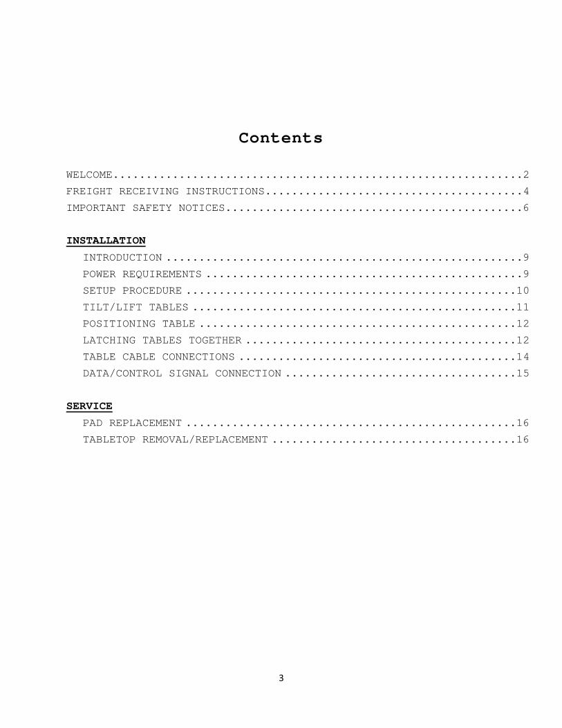
Contents
WELCOME..............................................................2
FREIGHT RECEIVING INSTRUCTIONS.......................................4
IMPORTANT SAFETY NOTICES.............................................6
INSTALLATION
INTRODUCTION ......................................................9
POWER REQUIREMENTS ................................................9
SETUP PROCEDURE ..................................................10
TILT/LIFT TABLES .................................................11
POSITIONING TABLE ................................................12
LATCHING TABLES TOGETHER .........................................12
TABLE CABLE CONNECTIONS ..........................................14
DATA/CONTROL SIGNAL CONNECTION ...................................15
SERVICE
PAD REPLACEMENT ..................................................16
TABLETOP REMOVAL/REPLACEMENT .....................................16

4
FREIGHT RECEIVING INSTRUCTIONS
Please follow the procedure below when receiving shipments.
I. When receiving and unloading a shipment, inspect all items
carefully. It is the responsibility of the receiver to
identify any damage or shortages at the time of equipment
receipt.
A. If a shortage occurs, note the specific item shorted on the
freight bill while the driver is present.
B. Check the shipment for obvious signs of damage to
containers, or note specifically which item is damaged.
Damage to containers may or may not mean damage to
merchandise. Damaged containers should be opened and the
extent of damage to merchandise should be noted on the
delivery receipt.
C. In the case of concealed damage (damage identified after the
shipment was accepted), it is important to do the following:
1. Immediately report hidden damage to the local terminal
(contact may be made by phone but must be followed up
in writing) and request an inspection to verify the
damage and to determine a cause. This must be done
within 15 days after receipt of delivery.
2. Retain all packaging for inspector (both outer
container and any inner packing) in the same condition
and area where the damage was discovered.
3. After inspection has been completed, damaged goods must
be held for carrier's advice as to disposition unless
merchandise can be repaired or sold at a reasonable
discount.
D. It is the duty of the consignee to accept freight even though damaged (unless damaged beyond repair and practically
worthless). The fact that goods are damaged during
transportation through causes for which the carrier is
responsible, does not of itself justify the consignee in
refusing to receive them. Consignee should accept delivery
and take all necessary steps to minimize the loss. If the
goods can be repaired for a reasonable amount, the consignee
5
should arrange for such repairs and file a claim with the
carrier. If goods can be sold at a reasonable price in
damaged condition, the consignee should arrange to sell the
merchandise and secure the best available price for them, and
then files a claim with the carrier for the loss, if any.
II. Take digital photos, if possible. These photos can
be sent to Nevco and the freight carrier.
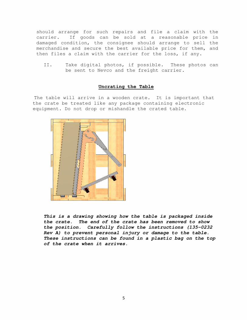
Uncrating the Table
The table will arrive in a wooden crate. It is important that
the crate be treated like any package containing electronic
equipment. Do not drop or mishandle the crated table.
This is a drawing showing how the table is packaged inside
the crate. The end of the crate has been removed to show
the position. Carefully follow the instructions (135-0232
Rev A) to prevent personal injury or damage to the table.
These instructions can be found in a plastic bag on the top
of the crate when it arrives.

6
IMPORTANT SAFETY NOTICES
The words WARNING, CAUTION, and NOTE are used throughout
this manual to call attention to important information
directives. The definition of each is as follows:
WARNING: A procedure which, if not properly followed, may
cause serious injury or death to yourself or
others. Equipment may also sustain damage if a
warning is disregarded.
CAUTION: A procedure which may cause slight injury or damage
to the equipment.
NOTE: A procedure which aids during installation and
service of the equipment
.
WARNING: All instructions in this manual should be strictly
observed for safety reasons and to preserve the
product warranty.
WARNING: Read and understand this instruction manual and
your employer’s safety practices before attempting
to work on equipment described in this manual.
Follow all OSHA (Occupational Safety and
Health Administration), State, and Local
regulations and guidelines which may be relevant to
the work being performed.
WARNING: Appropriate safety harnesses should be used by all
personnel working above ground level.
WARNING: Before opening the cabinet, be certain all power is
turned off at the main breaker panel. There may be
up to 240 Volts A.C. in the display cabinet. The
power may be turned on for troubleshooting after
the equipment is opened, but only by qualified
personnel.

7
WARNING: All power connections are to be made by a licensed
electrician in strict accordance with the latest
National Electric Code and any Local codes which
may apply.
8
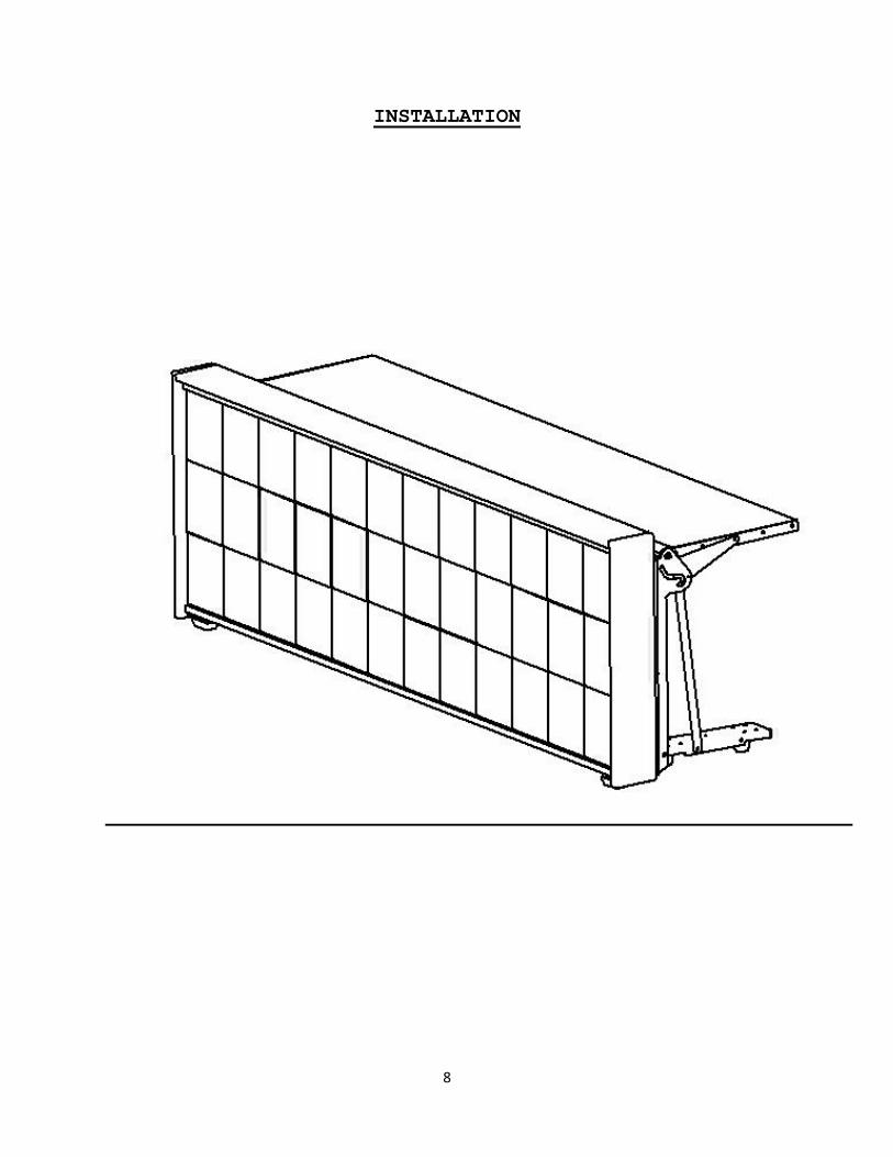
INSTALLATION

9
INTRODUCTION
This manual covers the installation and service of 3-in-1
Scorer's Table.
Please review this manual carefully before proceeding with the
installation. Some variations in the cabinet design and
electrical power run may occur on any given installation.
CAUTION: All instructions in this manual should be followed
both for safety reasons and to preserve the product warranty.
POWER REQUIREMENTS
The "power run" is the main power which goes out to the Scorer's
Table location from a fused breaker panel or disconnect located
inside your facility. This power run should be installed by a
licensed electrician in accordance with all governing laws and
codes that affect the area of installation.
The power required for the display cartridge is found in the
table in Appendix A. Each table has its own standard NEMA 5-15
power cord for applying power to the cartridge of the table.
Each table also has a row of 120Vac convenience power outlets
for powering computers, scoring equipment and other electrical
items that may be needed at the table location. Nevco recommends
that you provide at least a 10-Amp service to these outlets on
each table. This outlet strip is on its own power cord and
separate from the one that runs the backlighting or LEDs for the
display. This is done so that the customer has the option of
powering the displays separate from the control equipment if
they prefer. The power strip is capable of 20Amps but this is
not typically needed for low power devices that are typically
used on the table top. The power cord for the display is located
under the table top on the back left of the cabinet (as viewed
from the back) and the power cord for the convenience power
outlets is located under the table top in the middle of the
cabinet.

10
SETUP PROCEDURE
1) Position tables close to where they need to be
located/used.
2) Lift all scorers’ tables.
3) Make sure all data & power cables are stored away from the
pinch points between the tables so they cannot be damaged when
tables are latched together.
4) Position the first table where it needs to go.
5) Position and latch the next table to it. (Make sure table
are inline and straight with one another.)
6) Repeat step five until all tables are connected.
7) Connect the data cables (black RJ-45 Ethernet Cable) from
table to table, and the NEMA power cable. All connections will
be located under the table top.
8) Connect the main power to the NEMA power cable.
9) Connect the main data/Ethernet connection to the sign.
(RJ45 or HDMI)
10) Verify that the LED video display works properly.
11) Verify that every table has 120Vac to its convenience power
outlets.

11
TILT / LIFT TABLES
CAUTION: Tables should only be tilted or lifted on a level
surface. When a table is in the tilted position it
becomes very easy to move and will start rolling if
the surface is not level.
CAUTION: The tables should not be latched together unless
all tables have been lifted first. This is needed
to prevent physical damage to the tables/signs and
also to keep power and data cables from getting
pinched and damaged.
CAUTION: Tables should only be moved when they are in the
tilted position.
To lift the scorers table you will need to lift or “swing” the
table top upwards while pushing the cabinet forward to a
vertical position. (Figure 1-3)
Figure 1-3

12
POSITIONING TABLE
After the tables have been tilted they can be rolled to the
location where needed. The tilted position allows the tables to
be easily moved and turned.
Position the tables so that they are in the proper order. Each
table is numbered to identify its proper location. Each table
is labeled in the wire tray in line with the power strip. The
numbering starts on the right most table as viewed from the back
side. If you have more than one set of table configurations,
these labels will also be labeled to indicate the proper set
each table goes with. Example: If you have a 6-Table
configuration for one side of the gym and a 2-Table
configuration for the other; you will have the following labels:
A1, A2, A3, A4, A5, A6, B1, & B2. All of the "A" tables are for
the 6-table configuration and the "B" tables for the 2-table
configuration.
LATCHING TWO OR MORE TABLES TOGETHER
Each table is equipped with a mechanical latch on each end. This
allows the individual tables to be locked together to form one
long continuous table and also make sure that the LED video
display is properly aligned for proper video and graphic
projection without gaps or skew. To operate the latches you
will need the 5/16" extended Allen driver provided with each
setup. See the following pictures that show the Allen driver
and latch locations.
Figure 1-5(Latch Close-Up)
13
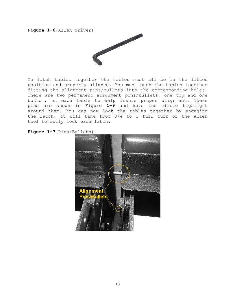
Figure 1-6(Allen driver)
To latch tables together the tables must all be in the lifted
position and properly aligned. You must push the tables together
fitting the alignment pins/bullets into the corresponding holes.
There are two permanent alignment pins/bullets, one top and one
bottom, on each table to help insure proper alignment. These
pins are shown in Figure 1-9 and have the circle highlight
around them. You can now lock the tables together by engaging
the latch. It will take from 3/4 to 1 full turn of the Allen
tool to fully lock each latch.
Figure 1-7(Pins/Bullets)

14
TABLE CABLE CONNECTIONS
There are three standard cable connections that need to be made
to each table. They all must be connected and latched correctly
for everything to function properly. Each is described here:
Data Cable: The data cable is for the LED video display.
The displays must be all connected together to allow the
video information and function control signals to be sent.
This cable looks like a standard RJ-45 LAN/Ethernet cable.
There is a RJ-45 port connector on each end of the table
for this cable to plug into. See Figures 1-10 thru 1-12
for connection view.
Power Cable: This will be a black heavy cord with a NEMA
power connector on the end. This cable must be connected
to allow power to get to the table. Each of these tables
will be powered separately by its own power service/cord.
Convenience Power Outlets: The Convenience Power Outlet is
a standard 6-plex power module that is built into the
table. The cord for this convenience power hangs out the
backside of the scorers table below the table top. This
cord should be plugged into the receptacle provided on the
backside of the scorers table.
Figure (1-6)

15
DATA/CONTROL SIGNAL CONNECTION
There will be one or more of the following connections needed to
properly allow the user to control the LED video display:
> HDMI video port (standard). This is a video port used to
connect the dislay director laptop included with the
scorer’s table shipment. Connect the laptop to the HDMI
port and you are up and running.
> RJ-45 input/output ports. This port is used for tables
that are used in conjunction with other LED tables. The
table with the HDMI cable is the master table and
Ethernet cables feed data from the master table to the
connecting tables.
> Video Data RJ-45 port. This connector/port looks just
like a standard Ethernet port but must NOT be connected
to a LAN or computer Ethernet port. This connection goes
from the Nevco provided video player directly to the LED
video display. This is typically used for a system
integrating scorer’s tables with other LED video
displays.
The type of the ports listed above configured on the table is
predetermined by the user when the tables are ordered.
For each multi-display setups there will be one "Client"
computer for each display and a director computer that tells all
of the client computers what to do. The director computer is the
one that runs the video or graphics as needed on command. The
player/decoder unit is a Nevco assembly that converts the DVI
signal, coming out of the client computer, to a format that the
LED video displays need. Depending on how the system is
ordered, these items can either be located in the tables or back
in a remote media room. In addition to the client computer is a
desktop or laptop computer that is needed for user interaction
with the display. In some cases the Admin & Client computers can
be combined into one.

16
SERVICE
PAD REPLACEMENT
Any of the pads may at some point need replacement. They are
the end pad, and the top pad.
The end pads come as a removable part that is held in place by
keyhole locks located on each end of the table. All you have to
do is lift these pads off the keyhole knobs and replace them
with the new pads.
The top pad is held in place by a hook and loop fastening
system. To remove the top pad lift gently at a single location
towards the end of the pad and continue lifting until the pad is
free.
TABLETOP REMOVAL/REPLACEMENT
Removing or installing a tabletop is a two person job, with each
person located and holding onto opposite ends of the tabletop.
With the tabletop in its lifted position the tabletop will need
to be unbolted from the shoulder bolts on the end of the tables.
Then the right rear vertical leg assembly should be loosened
from the frame. With the leg assembly loose, you can now remove
the table from the support hole on the vertical leg assembly.
The table is now free to remove. Install a tabletop by reversing
this procedure.

17
Appendix A
Non-Lit and Rear-Lit Signage Options
MODEL
NUMBER BACK-
LIGHTING DIMENSIONS TABLE
DEPTH IMPRINTABLE
AREA UPGRADEABLE EXPANDABLE POWER
(DISPLAY ONLY)
WT
LBS AMPS @ 120 VAC
ST-4-NL Non-Lit 4’L x 2’9”H x 34”D 1.2 x 0.88 x 0.85 m
19” (48cm) 46” x 29.50” Yes Yes n/a 115 n/a
ST-4-RL Rear-Lit 19” (48cm) 46” x 29.50” Yes Yes 24W 125 0.2
ST-8-NL Non-Lit 8’L x 2’9”H x 34”D 2.4 x 0.88 x 0.85 m
19” (48cm) 93.25” x 29.50” Yes Yes n/a 180 n/a
ST-8-RL Rear-Lit 19” (48cm) 93.25” x 29.50” Yes Yes 60W 190 0.5
ST-10-NL Non-Lit 10’L x 2’9”H x 34”D 3.05 x 0.88 x 0.85 m
19” (48cm) 112.25” x 29.50” Yes Yes n/a 210 n/a
ST-10-RL Rear-Lit 19” (48cm) 112.25” x 29.50” Yes Yes 60W 220 0.5
LED Options
MODEL NUMBER PITCH
MM COLOR DIMENSIONS TABLE DEPTH V PIXELS H PIXELS POWER
(DISPLAY ONLY)
WT
LBS AMPS @ 120 VAC
ST-8-LED-192 10 RGB Full Color 8’L x 2’9”H x 34”D 2.4 x 0.88 x 0.85 m
19” (48cm) 72 192 564 W 225 4.7
ST-8-LEDX240 10 RGB Full Color 19” (48cm) 72 240 696 W 230 5.8
ST-10-LEDX240 10 RGB Full Color 10’L x 2’9”H x 34”D 3.05 x 0.88 x 0.85 m
19” (48cm) 72 240 696 W 245 5.8
ST-10-LEDX288 10 RGB Full Color 19” (48cm) 72 288 840 W 250 7.0