Embed Size (px)
Citation preview
Instruction Manual - Loader
HMF 99781

Instruction Manual, Loaders
3HMF Technical Service Department Rev. 36-08
Important:
It is the employer’s responsibility that the loader operator has received the necessary instruction in operating the loader.
The operator must be familiar with the directions and instruction of this instruction manual as well as the HMF Safety Manual and the HMF Instruction Manual concerning the RCL Safety System.

Instruction Manual, Loaders
4HMF Technical Service Department Rev. 36-08
Instruction Manual, Loaders
5HMF Technical Service Department Rev. 36-08
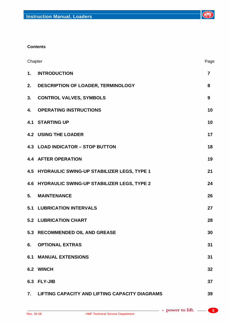
Contents Chapter Page
1. INTRODUCTION 7
2. DESCRIPTION OF LOADER, TERMINOLOGY 8
3. CONTROL VALVES, SYMBOLS 9
4. OPERATING INSTRUCTIONS 10
4.1 STARTING UP 10
4.2 USING THE LOADER 17
4.3 LOAD INDICATOR – STOP BUTTON 18
4.4 AFTER OPERATION 19
4.5 HYDRAULIC SWING-UP STABILIZER LEGS, TYPE 1 21
4.6 HYDRAULIC SWING-UP STABILIZER LEGS, TYPE 2 24
5. MAINTENANCE 26
5.1 LUBRICATION INTERVALS 27
5.2 LUBRICATION CHART 28
5.3 RECOMMENDED OIL AND GREASE 30
6. OPTIONAL EXTRAS 31
6.1 MANUAL EXTENSIONS 31
6.2 WINCH 32
6.3 FLY-JIB 37
7. LIFTING CAPACITY AND LIFTING CAPACITY DIAGRAMS 39
Instruction Manual, Loaders
6HMF Technical Service Department Rev. 36-08
7.1 LIFTING CAPACITY LABELS ON THE LOADER 39
7.2 LIFTING CAPACITY DIAGRAMS 39
8. TECHNICAL DATA 40
8.1 LOADING GROUPS 40
9. WORKING PRESSURE AND PUMP PERFORMANCE 40
10. DESCRIPTION OF THE HYDRAULIC SYSTEM 41
11. LOAD MOMENT LIMITATION 42
12. HEAVY DUTY LIFTING - HDL 42
13. HOSES AND HYDRAULIC PIPES 43
14. BLEEDING OF AIR 43
15. REPAIR 43
Instruction Manual, Loaders
7HMF Technical Service Department Rev. 36-08
1. Introduction This instruction manual contains a description of the loader, instructions for operation as well as for maintenance and servicing of the loader. The instruction manual includes the following chapters: Chapters 1 through 8 contain general instructions for the daily operation of the loader. Chapters 9 through 15 are primarily aimed at operators, mounting and maintenance personnel and contain instructions for mounting, adjustment, inspection and maintenance. It is very important that you familiarize yourself with the contents of this manual before putting the loader into operation; the same of course applies to any assistants or co-users of the loader. This also goes for the other manuals and instructions delivered together with the loader, especially the Safety Manual, the Instruction Manual – RCL Safety System, as well as the Service Booklet. It is also important to attend the recommended service overhauls. These service overhauls are designed to ensure operational safety at all times and will also be of importance in case of warranty claims at a later stage, where great importance will be attached to whether these overhauls have been carried through by an authorized HMF service point or not. As HMF is constantly developing and improving the loaders, your loader model may have been changed slightly since printing of this instruction manual.
Instruction Manual, Loaders
8HMF Technical Service Department Rev. 36-08
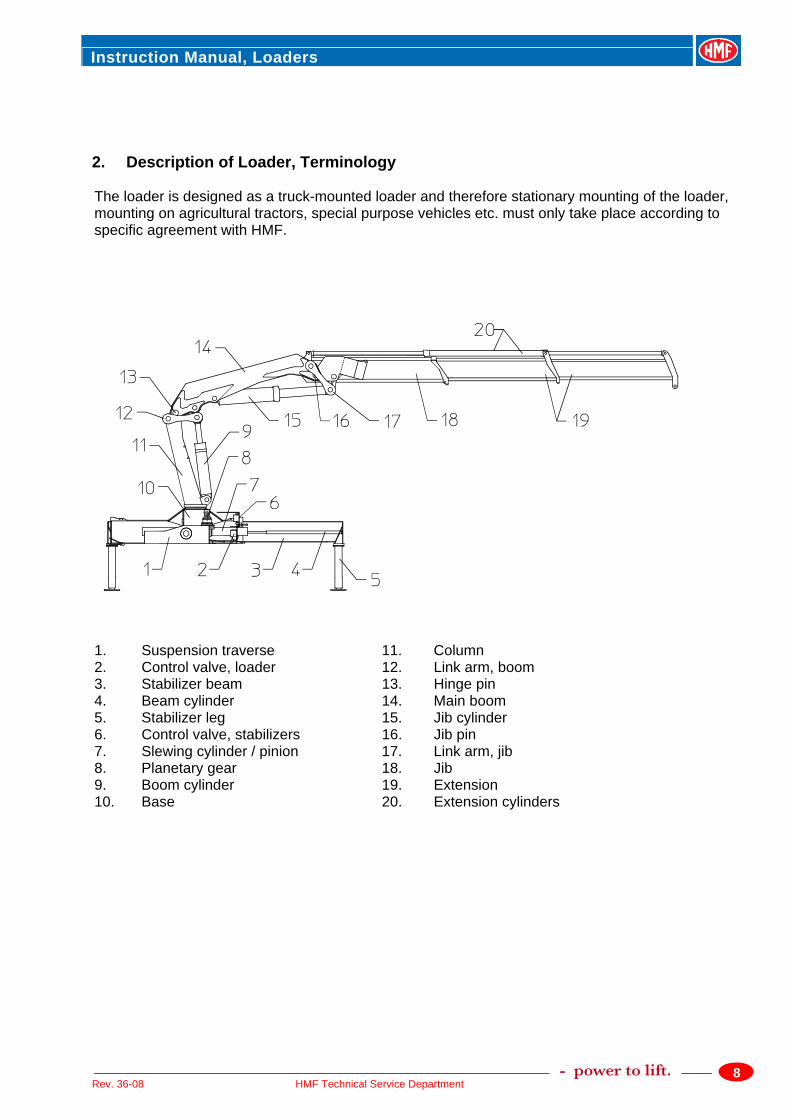
2. Description of Loader, Terminology The loader is designed as a truck-mounted loader and therefore stationary mounting of the loader, mounting on agricultural tractors, special purpose vehicles etc. must only take place according to specific agreement with HMF.
1. Suspension traverse 11. Column 2. Control valve, loader 12. Link arm, boom 3. Stabilizer beam 13. Hinge pin 4. Beam cylinder 14. Main boom 5. Stabilizer leg 15. Jib cylinder 6. Control valve, stabilizers 16. Jib pin 7. Slewing cylinder / pinion 17. Link arm, jib 8. Planetary gear 18. Jib 9. Boom cylinder 19. Extension 10. Base 20. Extension cylinders
Instruction Manual, Loaders
9HMF Technical Service Department Rev. 36-08
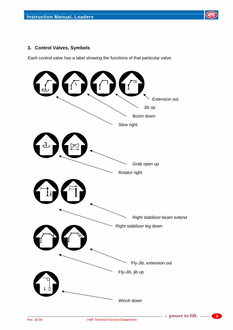
3. Control Valves, Symbols Each control valve has a label showing the functions of that particular valve.
Right stabilizer leg down
Right stabilizer beam extend
Slew right
Boom down
Jib up
Extension out
Winch down
Fly-Jib, extension out
Fly-Jib, jib up
Rotator right
Grab open up
Instruction Manual, Loaders
10HMF Technical Service Department Rev. 36-08
4. Operating Instructions 4.1 Starting Up Before loader operation, the operator must make sure that the loader operation does not entail any unnecessary risk. Special attention must be paid to the following factors: 1. The ground must be sufficiently firm to take up the pressure from the stabilizer legs. Use of
steel plates under the foot plates are recommended in case of heavy lifting. 2. The ground must not be slippery (i.e. covered with ice or sand). When the parking brake is
applied, the truck must be able to take up the horizontal forces from the loader without skidding or moving.
3. The truck must be parked in such a way that the operator has a complete view of the
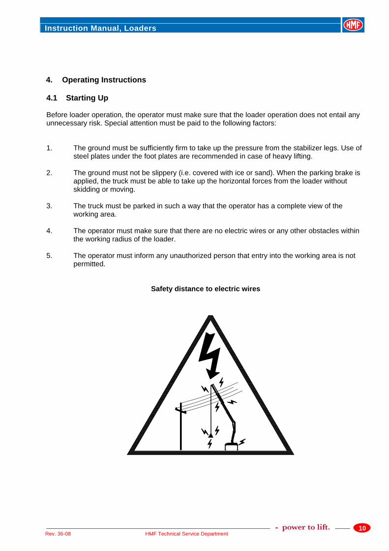
working area. 4. The operator must make sure that there are no electric wires or any other obstacles within
the working radius of the loader. 5. The operator must inform any unauthorized person that entry into the working area is not
permitted.
Safety distance to electric wires
Instruction Manual, Loaders
11HMF Technical Service Department Rev. 36-08
General rules: For all work in the proximity of power plants or overhead wires the following general rules apply: 1. Due care and caution must be exercised in the planning, instructing for and execution of
such work in order to prevent any risk or danger to people, equipment or goods. 2. Any power supply plant, installation or wire must be considered live until the responsible
power supply authority has provided a declaration to the opposite effect. 3. Any directions or guidelines from the responsible power supply authorities or public bodies
should be strictly observed. Any person or company directly responsible for the implementation of work in the proximity of overhead wires or electric power stations must make sure that all personnel involved in the execution of such work is familiar with any laws, rules or safety regulations, national as well as local, governing such work in the relevant country, territory or zone. Not until the operator has checked the above may loader operation start. 1. Switch the change-over valve, if any, to “loader”. 2. Engage the PTO at low revolutions. The engine revolution speed is regulated by means of the hand accelerator in order to
ensure that the oil flow from the hydraulic pump corresponds to the recommended pump flow for the loader.
When starting up in the cold, the oil should be allowed to circulate for a few minutes before operation starts.
3. Activate the parking brake of the vehicle. 4. Starting up:
a) Pull out the stop button – remember both sides of the loader, if necessary.
b) Push the green button once, the “RUN” diode is lit and the safety system is activated.
Instruction Manual, Loaders
12HMF Technical Service Department Rev. 36-08
Stabilizer function: c) Push the yellow button twice and the “FUNC” and “F5” diodes are lit. After 2 seconds
the diodes are turned off, but the stabilizer function remains activated. Now the stabilizer function is activated and items 5 through -7 below must be carried
out. Please note: On certain loader models the stabilizers are operated by means of the radio remote
control. Please see the IRC Instruction Manual .
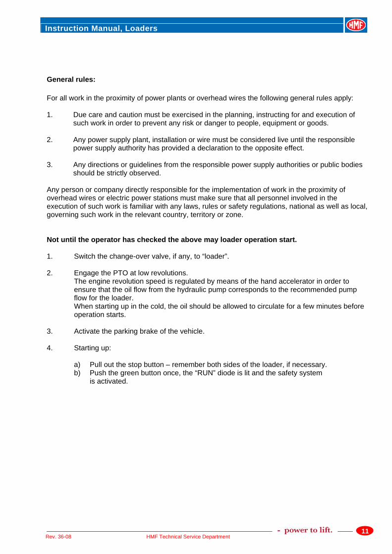
Loader function: d) Either: Activate one of the control levers of the loader’s control valve or: Push the yellow button twice; “FUNC” is lit and “F5” is turned off. All loader functions are now activated – carry out item 8. 5. Release the stabilizer lock and the safety lock, extend the stabilizer beam completely, and
lock it again. If the loader is equipped with a hydraulic extension function, it must only be used for extending and retracting the stabilizer beam. The stability of the loader and the vehicle is based on the stabilizers in their extreme position and the loader should only be used at maximum stabilizer spread. The operator must know whether or not the vehicle is stable in the area in front of the stabilizers (over the driver’s cab). Lower the stabilizer legs just enough to raise the truck chassis a little in its suspensions. The wheels must still have full contact with the ground. During loading of the truck the stabilizer legs must be raised from time to time, to ensure that the truck carries the weight of the load. The stabilizer legs are not designed to support this excessive load.
6. The best possible loader operation will be achieved when the vehicle is positioned as close
to horizontal as possible. Therefore, the vehicle should be levelled to horizontal position by means of the stabilizer legs before the loader is operated.
7. If the ground is not firm enough to take up the pressure of the stabilizer legs, a steel plate,
or the like must be placed under the foot plates.
Instruction Manual, Loaders
13HMF Technical Service Department Rev. 36-08
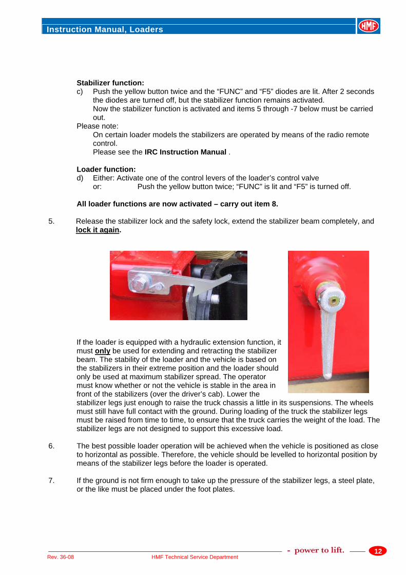
8. Unfolding the loader 8.1 Unfolding of a knuckle boom loader takes place as set out below.
I Extend the stabilizer beams completely. This also goes for the separate traverse (if any). II Lower the stabilizer legs according to items 5, 6, and 7 above. This also goes for the separate traverse (if any). III Important: The jib must be raised (the “jib down” movement of the lever), so that the jib is released
from the bracket. IV Raise the main boom and thereby release it from the bracket. Raise the main boom
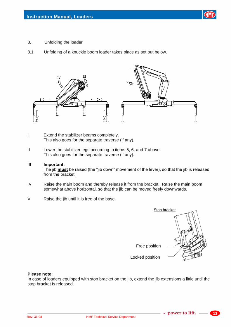
somewhat above horizontal, so that the jib can be moved freely downwards. V Raise the jib until it is free of the base. Please note: In case of loaders equipped with stop bracket on the jib, extend the jib extensions a little until the stop bracket is released.
Free position
Locked position
Stop bracket
Instruction Manual, Loaders
14HMF Technical Service Department Rev. 36-08
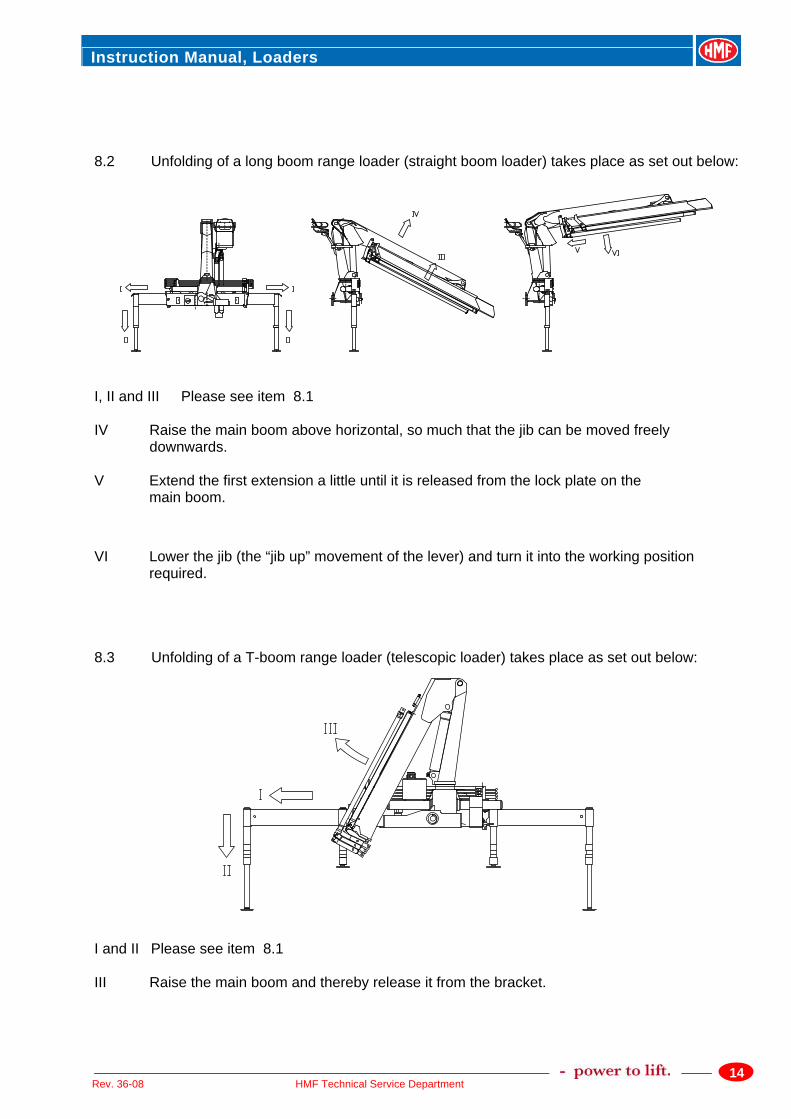
8.2 Unfolding of a long boom range loader (straight boom loader) takes place as set out below:
I, II and III Please see item 8.1 IV Raise the main boom above horizontal, so much that the jib can be moved freely
downwards. V Extend the first extension a little until it is released from the lock plate on the main boom.
VI Lower the jib (the “jib up” movement of the lever) and turn it into the working position
required. 8.3 Unfolding of a T-boom range loader (telescopic loader) takes place as set out below:
I and II Please see item 8.1 III Raise the main boom and thereby release it from the bracket.
Instruction Manual, Loaders
15HMF Technical Service Department Rev. 36-08
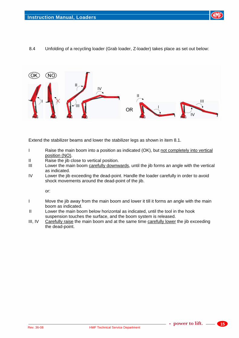
8.4 Unfolding of a recycling loader (Grab loader, Z-loader) takes place as set out below: Extend the stabilizer beams and lower the stabilizer legs as shown in item 8.1. I Raise the main boom into a position as indicated (OK), but not completely into vertical
position (NO). II Raise the jib close to vertical position. III Lower the main boom carefully downwards, until the jib forms an angle with the vertical
as indicated. IV Lower the jib exceeding the dead-point. Handle the loader carefully in order to avoid
shock movements around the dead-point of the jib. or: I Move the jib away from the main boom and lower it till it forms an angle with the main
boom as indicated. II Lower the main boom below horizontal as indicated, until the tool in the hook
suspension touches the surface, and the boom system is released. III, IV Carefully raise the main boom and at the same time carefully lower the jib exceeding
the dead-point.
Instruction Manual, Loaders
16HMF Technical Service Department Rev. 36-08
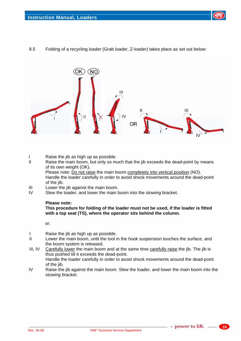
8.5 Folding of a recycling loader (Grab loader, Z-loader) takes place as set out below:
I Raise the jib as high up as possible. II Raise the main boom, but only so much that the jib exceeds the dead-point by means
of its own weight (OK). Please note: Do not raise the main boom completely into vertical position (NO).
Handle the loader carefully in order to avoid shock movements around the dead-point of the jib.
III Lower the jib against the main boom. IV Slew the loader, and lower the main boom into the stowing bracket.
Please note: This procedure for folding of the loader must not be used, if the loader is fitted with a top seat (TS), where the operator sits behind the column.
or:
I Raise the jib as high up as possible. II Lower the main boom, until the tool in the hook suspension touches the surface, and
the boom system is released. III, IV Carefully lower the main boom and at the same time carefully raise the jib. The jib is
thus pushed till it exceeds the dead-point. Handle the loader carefully in order to avoid shock movements around the dead-point of the jib.
IV Raise the jib against the main boom. Slew the loader, and lower the main boom into the stowing bracket.
Instruction Manual, Loaders
17HMF Technical Service Department Rev. 36-08
4.2 Using the Loader When the loader has been unfolded, the work can begin. The lifting capacity of the loader is shown on the lifting capacity diagram on the loader and in the Loader Data. The capacity limits indicated must never be exceeded. The loader is designed to lift loads vertically and therefore diagonal stresses should be avoided. Consequently it is not permitted to drag loads across the ground using the extension cylinders or the slewing system. These functions must only be activated once the load is free of the ground. When mounting a grab, the total weight (grab, rotator and sand/contents) must not exceed the loader’s lifting capacity at maximum reach. The grab/clamshell bucket must be used for moving excavated soil only. Excavating is not permitted. Damage caused by maloperation of the loader will not be covered by the guarantee. If the load is extended so far that the loader’s lifting capacity is exceeded, the load moment increasing movements will be stopped. Please see the Instruction Manual - RCL Safety System. As regards non CE-loaders, the main boom will slowly begin to sink in case of overloading. To stop this movement, the load should be brought closer towards the loader column by means of the “extension retract”-movement. Never stand under the boom when the loader is working ! Please Note: Position the truck as closely to the load as possible, so that the load can be lifted on the shortest possible boom. The slewing system should be operated with care, especially when the main boom is at an acute angle with the jib. Do not activate the stabilizers when the loader is working. Never drive off with a suspended load.
Instruction Manual, Loaders
18HMF Technical Service Department Rev. 36-08
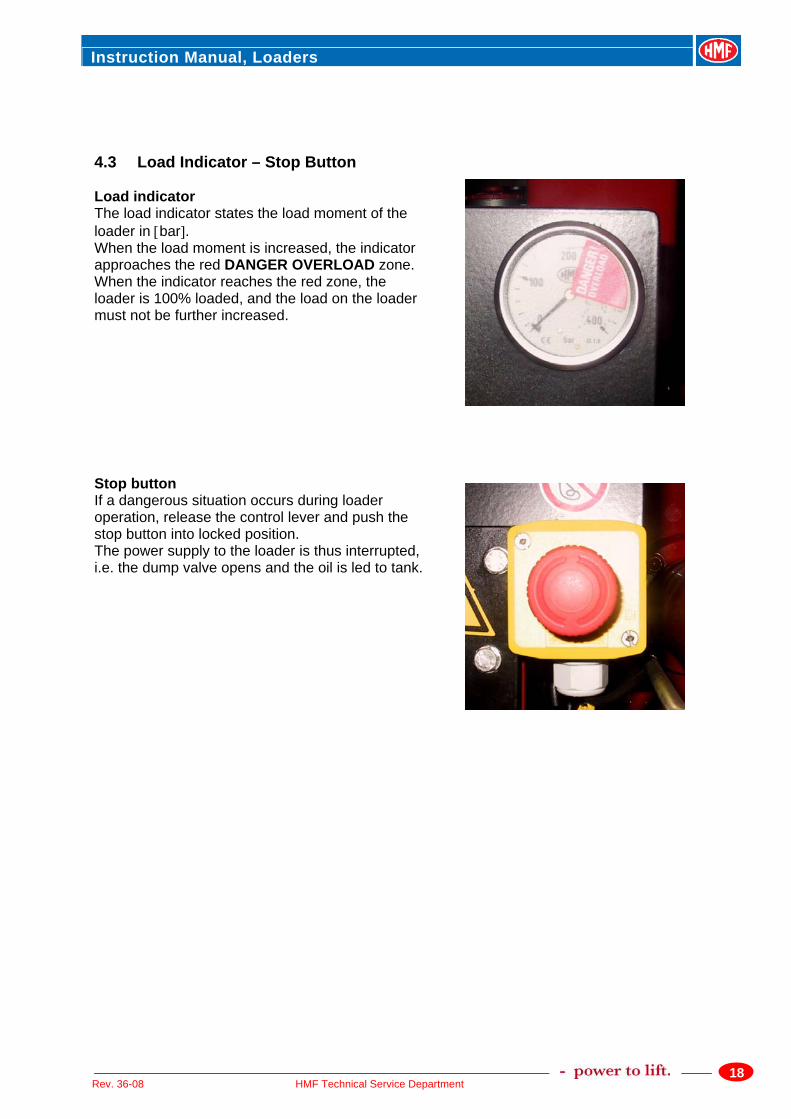
4.3 Load Indicator – Stop Button Load indicator The load indicator states the load moment of the loader in [bar]. When the load moment is increased, the indicator approaches the red DANGER OVERLOAD zone. When the indicator reaches the red zone, the loader is 100% loaded, and the load on the loader must not be further increased. Stop button If a dangerous situation occurs during loader operation, release the control lever and push the stop button into locked position. The power supply to the loader is thus interrupted, i.e. the dump valve opens and the oil is led to tank.
Instruction Manual, Loaders
19HMF Technical Service Department Rev. 36-08
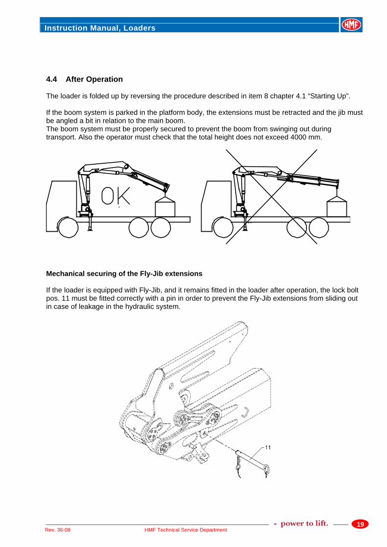
4.4 After Operation The loader is folded up by reversing the procedure described in item 8 chapter 4.1 “Starting Up”. If the boom system is parked in the platform body, the extensions must be retracted and the jib must be angled a bit in relation to the main boom. The boom system must be properly secured to prevent the boom from swinging out during transport. Also the operator must check that the total height does not exceed 4000 mm.
Mechanical securing of the Fly-Jib extensions If the loader is equipped with Fly-Jib, and it remains fitted in the loader after operation, the lock bolt pos. 11 must be fitted correctly with a pin in order to prevent the Fly-Jib extensions from sliding out in case of leakage in the hydraulic system.
Instruction Manual, Loaders
20HMF Technical Service Department Rev. 36-08
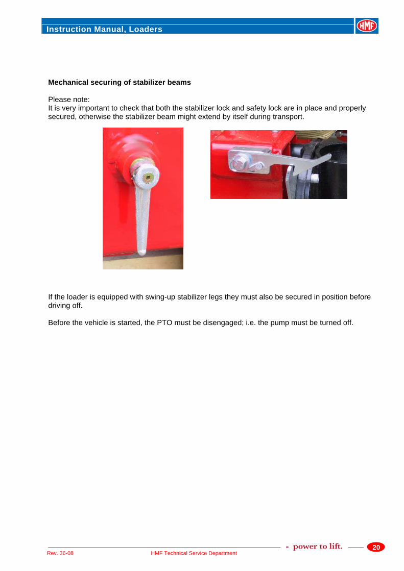
Mechanical securing of stabilizer beams Please note: It is very important to check that both the stabilizer lock and safety lock are in place and properly secured, otherwise the stabilizer beam might extend by itself during transport. If the loader is equipped with swing-up stabilizer legs they must also be secured in position before driving off. Before the vehicle is started, the PTO must be disengaged; i.e. the pump must be turned off.
Instruction Manual, Loaders
21HMF Technical Service Department Rev. 36-08
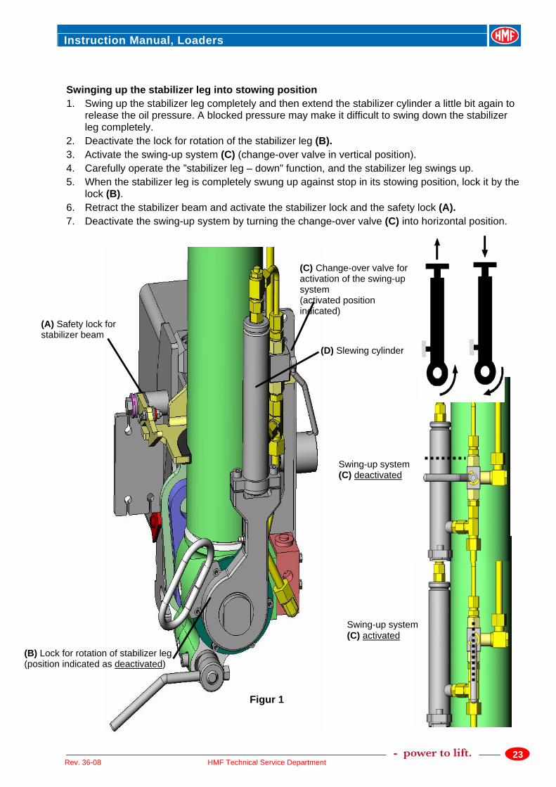
4.5 Hydraulic swing-up Stabilizer Legs, type 1 When the piston rod (D) of the slewing cylinder is extended (see figure 1), a swing-up mechanism is activated thus swinging up the stabilizer leg. The piston movement of the slewing cylinder is controlled by the piston movement of the stabilizer leg, when the swing-up system has been activated by means of the change-over valve (C). When activating the ”stabilizer – down” movement, the piston rod of the slewing cylinder is extended and the stabilizer leg swings up. Conversely the stabilizer leg swings down, when the “stabilizer – up” movement is activated. In case of a swing-up movement of 180°, the piston of the stabilizer leg moves approx. 25 mm. I.e. the stabilizer leg must be extended at least 25 mm, to be able to swing completely down. Important - with regards to personnel safety! • A safety distance of at least 1.5 metres to the rotation area of the stabilizer leg must be
observed when the stabilizer leg is swung up or down or when the stabilizer beam is extended.
• Always activate the lock for rotation of the stabilizer leg (B): when the stabilizer beam is retracted, while it is extended, and when the stabilizer leg is swung down.
• The stabilizer leg must be completely swung up against stop, and you must keep a safe distance to the rotation area of the stabilizer leg, before deactivating the lock for rotation of the stabilizer leg (B).
• If the vehicle is standing on a surface, which has an inclination of more than approx. 5 degrees in the direction of travel of the vehicle, it is not possible to swing down the stabilizer leg automatically from the stowing position. However, it is possible to swing down the stabilizer leg manually.
Swinging down the stabilizer leg from its stowing position 1. Important! Before extending the stabilizer beam, you must ensure that the piston rod is
completely extended from the slewing cylinder (D), i.e. that the stabilizer leg is completely swung up against stop in stowing position. Otherwise there is a risk of the stabilizer leg swinging down at uncontrolled speed. Carry out as follows:
Activate the swing-up system by turning the change-over valve (C) into vertical position. Carefully operate the ”stabilizer – down” movement (the stabilizer leg is swung up), until you are certain that the stabilizer leg is completely swung up.
Instruction Manual, Loaders
22HMF Technical Service Department Rev. 36-08
2. Make sure that the stabilizer leg is in a position where it is extended at least 30 mm. If it is not
extended, deactivate the swing-up system (change-over valve (C) is turned into horizontal position), and the stabilizer leg is extended until it is extended by at least 30 mm.
3. Make sure that the lock for rotation of the stabilizer leg (B) is activated. 4. Deactivate the stabilizer lock and the safety lock (A), and extend the beam completely. Keep a
safe distance to the rotation area of the stabilizer leg! If the stabilizer leg swings away from the stop in its stowing position, or if the stabilizer leg is swung down by mistake without the lock (B) being deactivated, you must repeat the procedure in item 1. Otherwise there is a risk of the stabilizer leg swinging down at uncontrolled speed, when deactivating the lock (B).
5. Deactivate the lock for rotation of the stabilizer leg (B), so that it is possible to swing down the stabilizer leg. Keep a safe distance to the rotation area of the stabilizer leg!
6. Make sure that the swing-up system is activated (change-over valve (C) in vertical position). 7. Carefully activate the ”stabilizer leg – up” function, and the stabilizer leg swings down. 8. When the stabilizer leg is completely swung down, lock it by the lock (B). 9. Deactivate the swing-up system by turning the change-over valve (C) into horizontal position. 10. Lower the stabilizer leg until the vehicle is correctly supported.
Instruction Manual, Loaders
23HMF Technical Service Department Rev. 36-08
Swinging up the stabilizer leg into stowing position 1. Swing up the stabilizer leg completely and then extend the stabilizer cylinder a little bit again to
release the oil pressure. A blocked pressure may make it difficult to swing down the stabilizer leg completely.
2. Deactivate the lock for rotation of the stabilizer leg (B). 3. Activate the swing-up system (C) (change-over valve in vertical position). 4. Carefully operate the ”stabilizer leg – down” function, and the stabilizer leg swings up. 5. When the stabilizer leg is completely swung up against stop in its stowing position, lock it by the
lock (B). 6. Retract the stabilizer beam and activate the stabilizer lock and the safety lock (A). 7. Deactivate the swing-up system by turning the change-over valve (C) into horizontal position.
(C) Change-over valve for activation of the swing-up system (activated position indicated)
(B) Lock for rotation of stabilizer leg (position indicated as deactivated)
(A) Safety lock for stabilizer beam (D) Slewing cylinder
Swing-up system (C) activated
Swing-up system (C) deactivated
Figur 1
Instruction Manual, Loaders
24HMF Technical Service Department Rev. 36-08
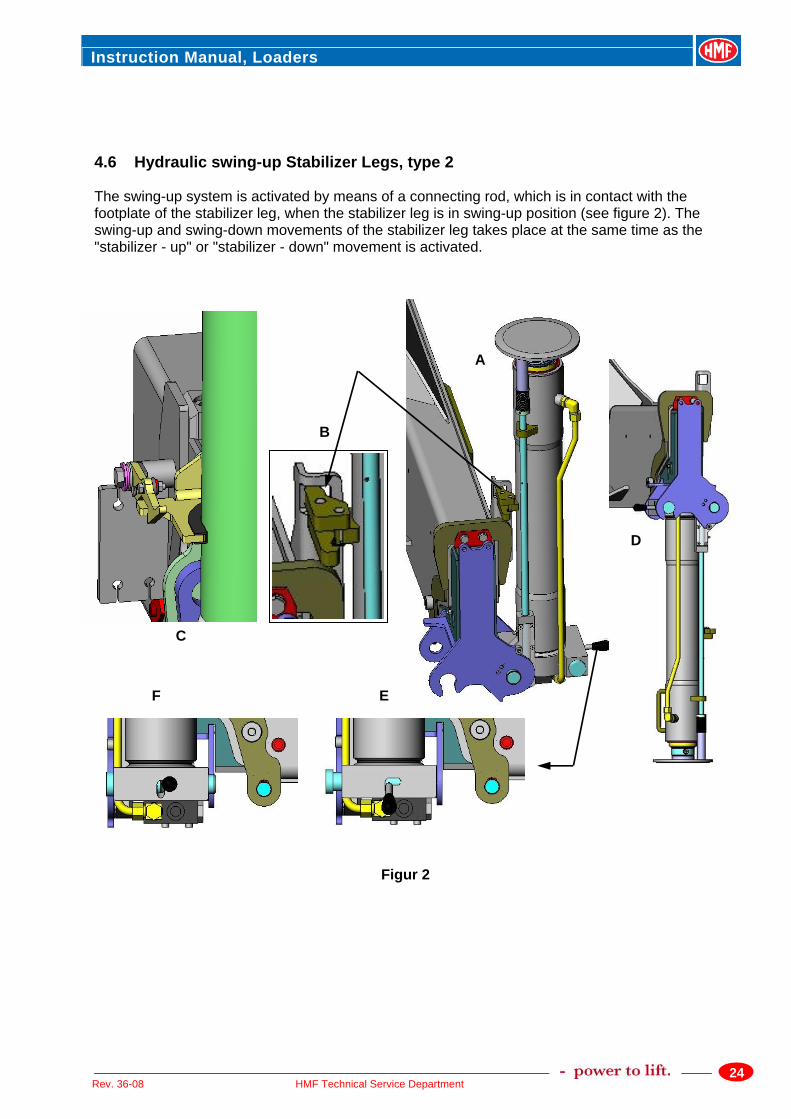
D
C
EF
B
A
Figur 2
4.6 Hydraulic swing-up Stabilizer Legs, type 2 The swing-up system is activated by means of a connecting rod, which is in contact with the footplate of the stabilizer leg, when the stabilizer leg is in swing-up position (see figure 2). The swing-up and swing-down movements of the stabilizer leg takes place at the same time as the "stabilizer - up" or "stabilizer - down" movement is activated.
Instruction Manual, Loaders
25HMF Technical Service Department Rev. 36-08
Swinging down the stabilizer leg from its stowing position 1. In stowing position (A) the stabilizer leg is fixed in a bracket (B). Before extending the stabilizer
beam, you must ensure that the stabilizer leg is completely swung up against stop in stowing position, and that the rod of the swing-up system is in contact with the footplate.
2. Deactivate the safety lock (C), and extend the stabilizer beam. Keep a safe distance to the rotation area of the stabilizer leg!
3. Deactivate the lock for rotation of the stabilizer leg – position (E), so that it is possible to swing down the stabilizer leg. Keep a safe distance to the rotation area of the stabilizer leg! If you try to swing down the stabilizer leg without deactivating this lock, you must repeat the procedure in item 1. Otherwise there is a risk of the stabilizer leg swinging down at uncontrolled speed, after deactivating the lock (E).
4. Carefully operate the ”stabilizer leg – down” function, and the stabilizer leg swings down. 5. When the stabilizer leg is completely swung down, activate the lock for rotation of the stabilizer
leg – position (F). 6. Lower the stabilizer leg until the vehicle is correctly supported. Swinging up the stabilizer leg into stowing position 1. Raise the stabilizer leg a little bit till the footplate no longer touches the surface. 2. Deactivate the lock for rotation of the stabilizer leg - position (E). 3. Raise the stabilizer leg – the last bit very slowly – until the rod of the swing-up system is in
contact with the footplate. 4. Carefully activate the ”stabilizer leg – up” function, and the stabilizer leg swings up. 5. When the stabilizer leg is completely swung up against stop in stowing position, activate the lock
for rotation of the stabilizer leg – position (F). 6. Retract the stabilizer beam and activate the safety lock (C).
Instruction Manual, Loaders
26HMF Technical Service Department Rev. 36-08
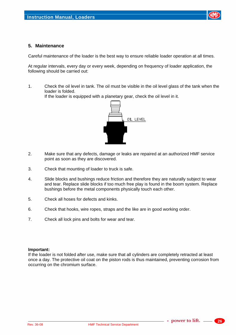
5. Maintenance Careful maintenance of the loader is the best way to ensure reliable loader operation at all times. At regular intervals, every day or every week, depending on frequency of loader application, the following should be carried out: 1. Check the oil level in tank. The oil must be visible in the oil level glass of the tank when the
loader is folded. If the loader is equipped with a planetary gear, check the oil level in it.
2. Make sure that any defects, damage or leaks are repaired at an authorized HMF service
point as soon as they are discovered. 3. Check that mounting of loader to truck is safe. 4. Slide blocks and bushings reduce friction and therefore they are naturally subject to wear
and tear. Replace slide blocks if too much free play is found in the boom system. Replace bushings before the metal components physically touch each other.
5. Check all hoses for defects and kinks. 6. Check that hooks, wire ropes, straps and the like are in good working order. 7. Check all lock pins and bolts for wear and tear. Important: If the loader is not folded after use, make sure that all cylinders are completely retracted at least once a day. The protective oil coat on the piston rods is thus maintained, preventing corrosion from occurring on the chromium surface.
Instruction Manual, Loaders
27HMF Technical Service Department Rev. 36-08
5.1 Lubrication Intervals The column/planetary gear: after 50 hours of operation /1 month (whatever occurs first) The pinion, if fitted: The ball bearings of the pinion: after 50 hours of operation /1 month (whatever occurs first) The rack/the pinion of the column after 50 hours of operation /1 month (whatever occurs first) (loader base excl. oil) Base bearings: after 20 hours of operation/1 week (whatever occurs first) Extension system/ after 50 hours of operation /1 month (whatever occurs first) slide blocks Guide rail on after 50 hours of operation /1 month (whatever occurs first) extension cylinders Pin connections/ after 50 hours of operation /1 month (whatever occurs first) bolts Stabilizer beams when required Control valves and when required rod connections (oil spray) Please note: After some time of standstill, the loader has to be lubricated again independently of the above lubrication intervals. Lubricate the loader according to the following lubrication chart.
Instruction Manual, Loaders
28HMF Technical Service Department Rev. 36-08
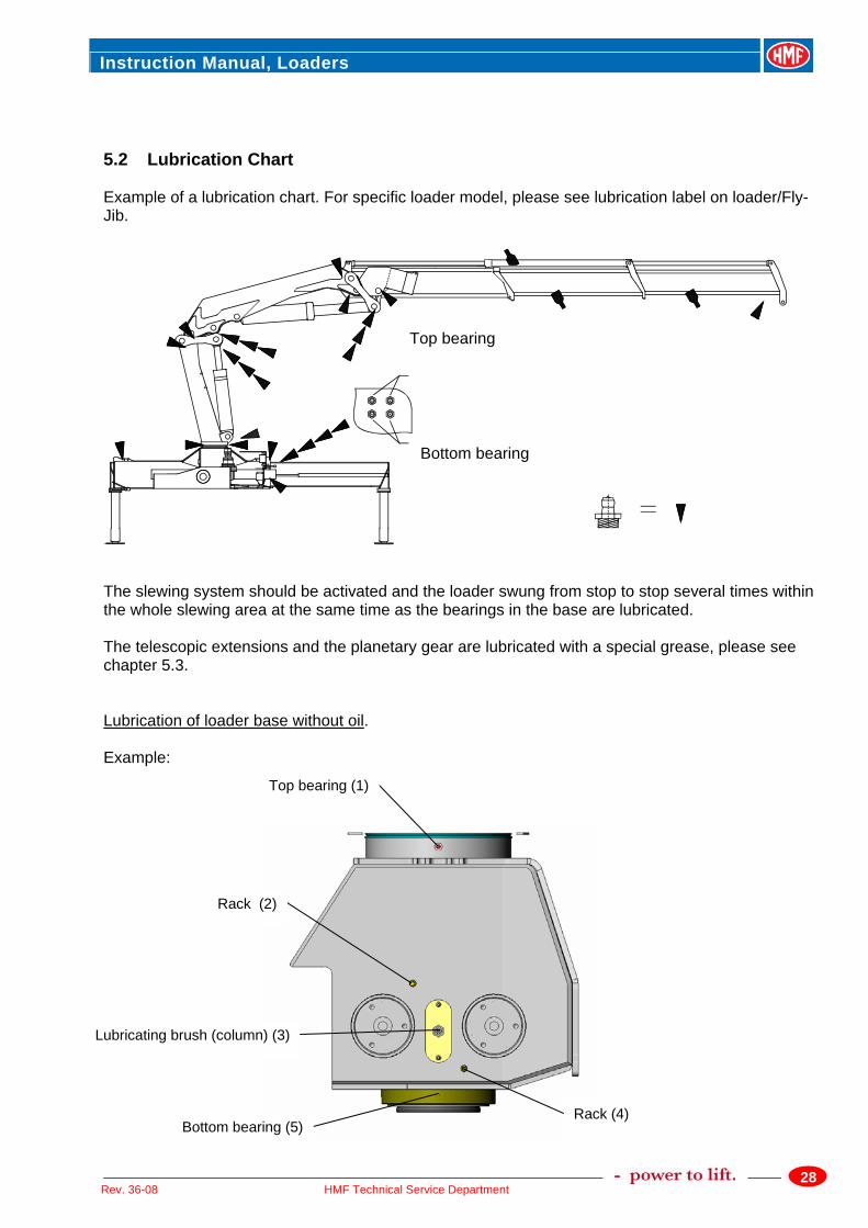
5.2 Lubrication Chart Example of a lubrication chart. For specific loader model, please see lubrication label on loader/Fly-Jib.
The slewing system should be activated and the loader swung from stop to stop several times within the whole slewing area at the same time as the bearings in the base are lubricated. The telescopic extensions and the planetary gear are lubricated with a special grease, please see chapter 5.3. Lubrication of loader base without oil. Example:
Top bearing
Bottom bearing
Lubricating brush (column) (3)
Rack (4)
Top bearing (1)
Rack (2)
Bottom bearing (5)
Instruction Manual, Loaders
29HMF Technical Service Department Rev. 36-08
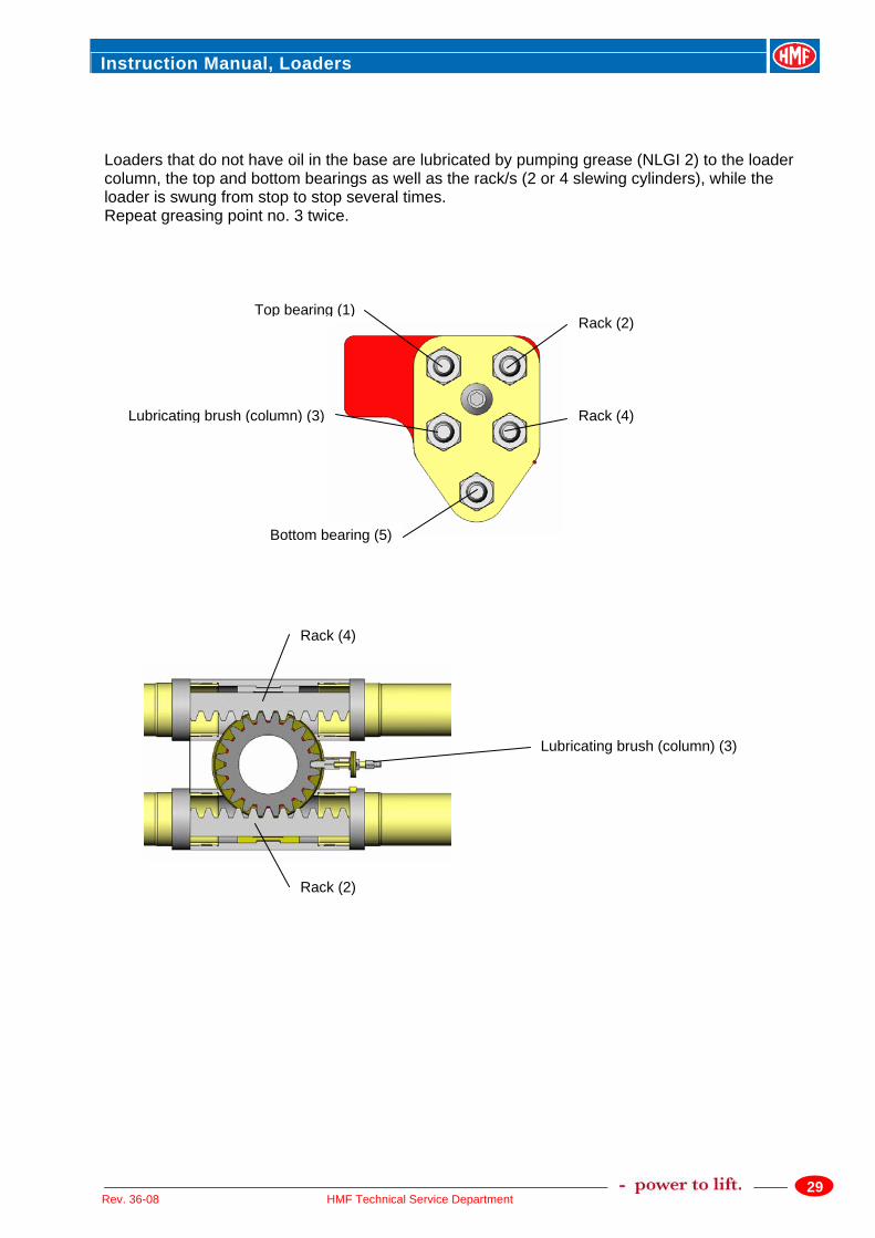
Loaders that do not have oil in the base are lubricated by pumping grease (NLGI 2) to the loader column, the top and bottom bearings as well as the rack/s (2 or 4 slewing cylinders), while the loader is swung from stop to stop several times. Repeat greasing point no. 3 twice.
Rack (2)
Rack (4) Lubricating brush (column) (3)
Bottom bearing (5)
Top bearing (1)
Lubricating brush (column) (3)
Rack (4)
Rack (2)
Instruction Manual, Loaders
30HMF Technical Service Department Rev. 36-08
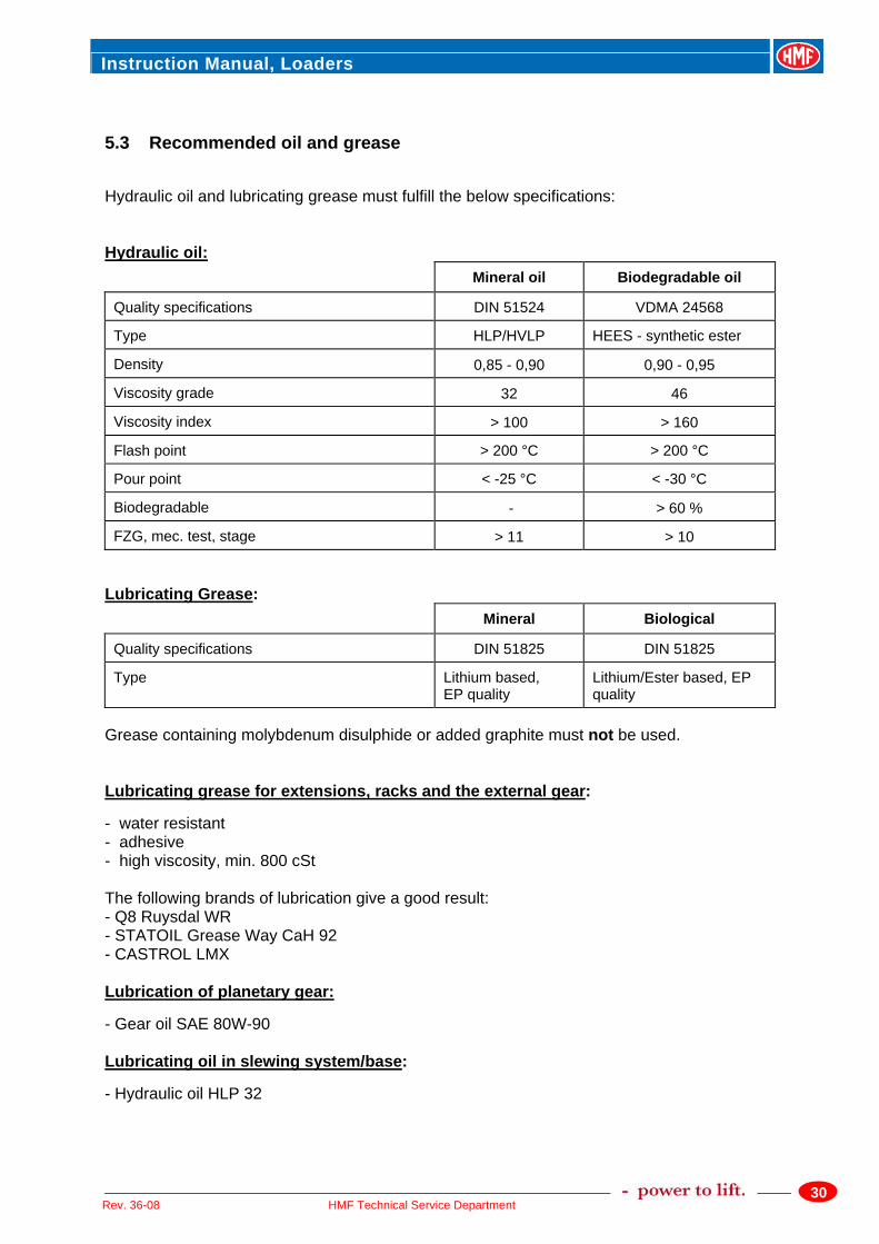
5.3 Recommended oil and grease Hydraulic oil and lubricating grease must fulfill the below specifications: Hydraulic oil: Mineral oil Biodegradable oil
Quality specifications DIN 51524 VDMA 24568
Type HLP/HVLP HEES - synthetic ester
Density 0,85 - 0,90 0,90 - 0,95
Viscosity grade 32 46
Viscosity index > 100 > 160
Flash point > 200 °C > 200 °C
Pour point < -25 °C < -30 °C
Biodegradable - > 60 %
FZG, mec. test, stage > 11 > 10 Lubricating Grease: Mineral Biological
Quality specifications DIN 51825 DIN 51825
Type Lithium based, EP quality
Lithium/Ester based, EP quality
Grease containing molybdenum disulphide or added graphite must not be used. Lubricating grease for extensions, racks and the external gear: - water resistant - adhesive - high viscosity, min. 800 cSt The following brands of lubrication give a good result: - Q8 Ruysdal WR - STATOIL Grease Way CaH 92 - CASTROL LMX Lubrication of planetary gear: - Gear oil SAE 80W-90 Lubricating oil in slewing system/base: - Hydraulic oil HLP 32
Instruction Manual, Loaders
31HMF Technical Service Department Rev. 36-08
6. Optional extras Various extras are available with the loader: • Fly-Jib • Manual extensions • Winch • Pallet fork • Grab / Rotator • Radio remote control Some loaders can as standard be equipped with optional extras such as manual extensions, winch and Fly-Jib. For these loaders you will – apart from the description in this manual – also find enclosed technical data and pressure setting diagrams as well as lifting capacity diagrams for the Fly-Jib. You should always consult an authorized HMF dealer/service point before mounting any kind of optional extra. This also applies to equipment already in your possession. Please note: All optional extras on the loader must be protected by the safety system. Please see the Instruction Manual – RCL Safety System. Welding onto or drilling into the structural components of the loader will automatically invalidate any liability on the part of HMF. 6.1 Manual Extensions When working with manual extensions, please note: The load limits indicated for manual extension must never be exceeded. Great care should be taken if the slewing system is to be activated during work with manual extensions. If the loader is fitted with manual extensions or other extras, the lifting capacity of the loader must be reduced by the weight of these extras. Always check that lock bolts are fitted correctly with a pin. If the loader is fitted with several extensions and a certain lifting job requires the use of one extension only, use the extension with the largest box profile. Only pull out the manual extensions when the jib is as close to horizontal as possible. If the jib is pointing downwards when the lock bolt is removed, the extensions will drop out at uncontrollable speed. This may ruin the stop at the risk of resulting in personal injury. The load must not be extended from the stop, i.e., the extension lock pins must always remain in place.
Instruction Manual, Loaders
32HMF Technical Service Department Rev. 36-08
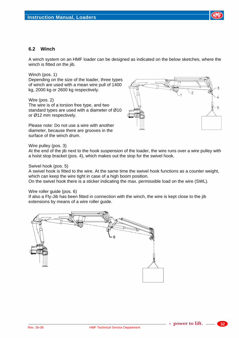
6.2 Winch A winch system on an HMF loader can be designed as indicated on the below sketches, where the winch is fitted on the jib. Winch (pos. 1) Depending on the size of the loader, three types of winch are used with a mean wire pull of 1400 kg, 2000 kg or 2600 kg respectively. Wire (pos. 2) The wire is of a torsion free type, and two standard types are used with a diameter of Ø10 or Ø12 mm respectively. Please note: Do not use a wire with another diameter, because there are grooves in the surface of the winch drum. Wire pulley (pos. 3) At the end of the jib next to the hook suspension of the loader, the wire runs over a wire pulley with a hoist stop bracket (pos. 4), which makes out the stop for the swivel hook. Swivel hook (pos. 5) A swivel hook is fitted to the wire. At the same time the swivel hook functions as a counter weight, which can keep the wire tight in case of a high boom position. On the swivel hook there is a sticker indicating the max. permissible load on the wire (SWL). Wire roller guide (pos. 6) If also a Fly-Jib has been fitted in connection with the winch, the wire is kept close to the jib extensions by means of a wire roller guide.
Instruction Manual, Loaders
33HMF Technical Service Department Rev. 36-08
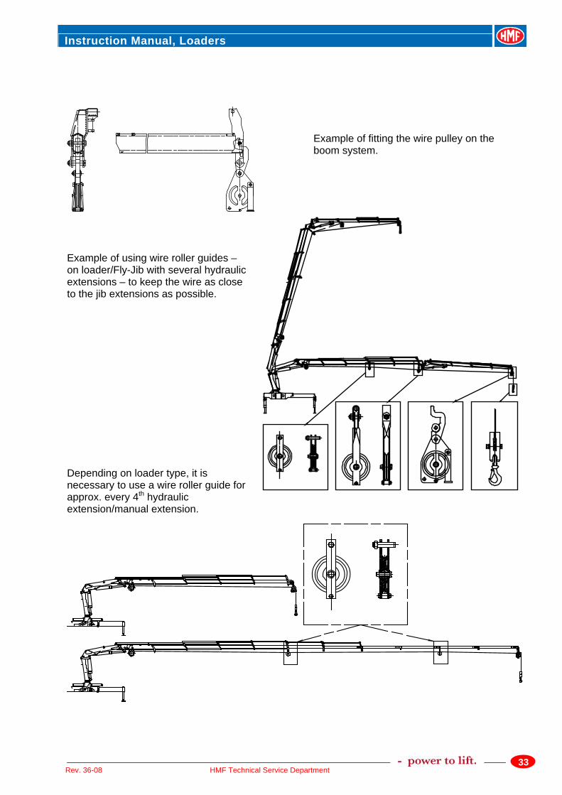
Example of fitting the wire pulley on the boom system.
Example of using wire roller guides – on loader/Fly-Jib with several hydraulic extensions – to keep the wire as close to the jib extensions as possible. Depending on loader type, it is necessary to use a wire roller guide for approx. every 4th hydraulic extension/manual extension.
Instruction Manual, Loaders
34HMF Technical Service Department Rev. 36-08
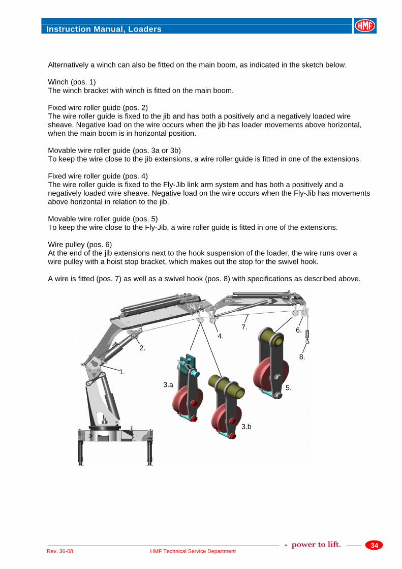
Alternatively a winch can also be fitted on the main boom, as indicated in the sketch below. Winch (pos. 1) The winch bracket with winch is fitted on the main boom. Fixed wire roller guide (pos. 2) The wire roller guide is fixed to the jib and has both a positively and a negatively loaded wire sheave. Negative load on the wire occurs when the jib has loader movements above horizontal, when the main boom is in horizontal position. Movable wire roller guide (pos. 3a or 3b) To keep the wire close to the jib extensions, a wire roller guide is fitted in one of the extensions. Fixed wire roller guide (pos. 4) The wire roller guide is fixed to the Fly-Jib link arm system and has both a positively and a negatively loaded wire sheave. Negative load on the wire occurs when the Fly-Jib has movements above horizontal in relation to the jib. Movable wire roller guide (pos. 5) To keep the wire close to the Fly-Jib, a wire roller guide is fitted in one of the extensions. Wire pulley (pos. 6) At the end of the jib extensions next to the hook suspension of the loader, the wire runs over a wire pulley with a hoist stop bracket, which makes out the stop for the swivel hook. A wire is fitted (pos. 7) as well as a swivel hook (pos. 8) with specifications as described above.
1.
2.
3.a
3.b
5.
4. 7.
8.
6.
Instruction Manual, Loaders
35HMF Technical Service Department Rev. 36-08
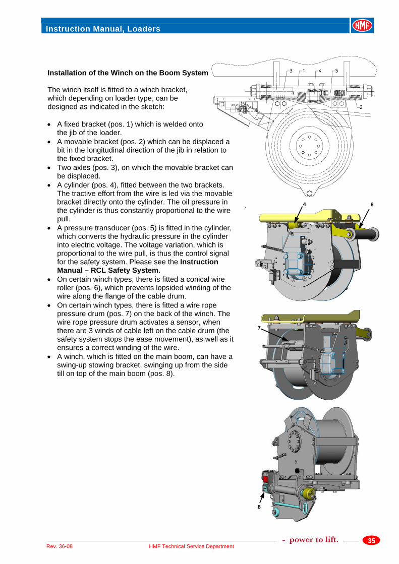
Installation of the Winch on the Boom System The winch itself is fitted to a winch bracket, which depending on loader type, can be designed as indicated in the sketch: • A fixed bracket (pos. 1) which is welded onto
the jib of the loader. • A movable bracket (pos. 2) which can be displaced a
bit in the longitudinal direction of the jib in relation to the fixed bracket.
• Two axles (pos. 3), on which the movable bracket can be displaced.
• A cylinder (pos. 4), fitted between the two brackets. The tractive effort from the wire is led via the movable bracket directly onto the cylinder. The oil pressure in the cylinder is thus constantly proportional to the wire pull.
• A pressure transducer (pos. 5) is fitted in the cylinder, which converts the hydraulic pressure in the cylinder into electric voltage. The voltage variation, which is proportional to the wire pull, is thus the control signal for the safety system. Please see the Instruction Manual – RCL Safety System.
• On certain winch types, there is fitted a conical wire roller (pos. 6), which prevents lopsided winding of the wire along the flange of the cable drum.
• On certain winch types, there is fitted a wire rope pressure drum (pos. 7) on the back of the winch. The wire rope pressure drum activates a sensor, when there are 3 winds of cable left on the cable drum (the safety system stops the ease movement), as well as it ensures a correct winding of the wire.
• A winch, which is fitted on the main boom, can have a swing-up stowing bracket, swinging up from the side till on top of the main boom (pos. 8).
4 6
8
7
Instruction Manual, Loaders
36HMF Technical Service Department Rev. 36-08
Warning when working with loader and
winch • The loader safety system prevents the loader and winch system from being overloaded, but
being the operator you are still responsible for safe operation of the loader/winch. • Do not try to lift a load that weighs more than indicated on the SWL label on the swivel hook.
The value indicates the max. permissible stress on the wire. • Always operate the winch in a considerate way, and make sure that the wire has a correct
winding and not for instance lopsided winding. • Never make diagonal movements with the winch. Only make vertical lifts with a winch. • Never drag a load across a surface. The winch is only meant for lifting vertically. • Constantly keep the wire tight when working with a winch. Stop the winch down movement as
soon as the load is placed on the surface. • Always operate the winch up movement carefully when the hook reaches the hoist stop. • Avoid fast movements with the winch when working at a long reach. • Avoid oscillation of the load when it is hanging in a long wire. • Operate the winch carefully up and down, when working in high positions with loader and Fly-
Jib, if any. • Extend the jib extensions to the position where the load is to be handled by means of the winch.
Avoid extending the extensions on the loader and the Fly-Jib when a load is hanging in the wire. • Always respect when the safety system stops the loader/winch function and check what was the
reason for the loader stop.
Instruction Manual, Loaders
37HMF Technical Service Department Rev. 36-08
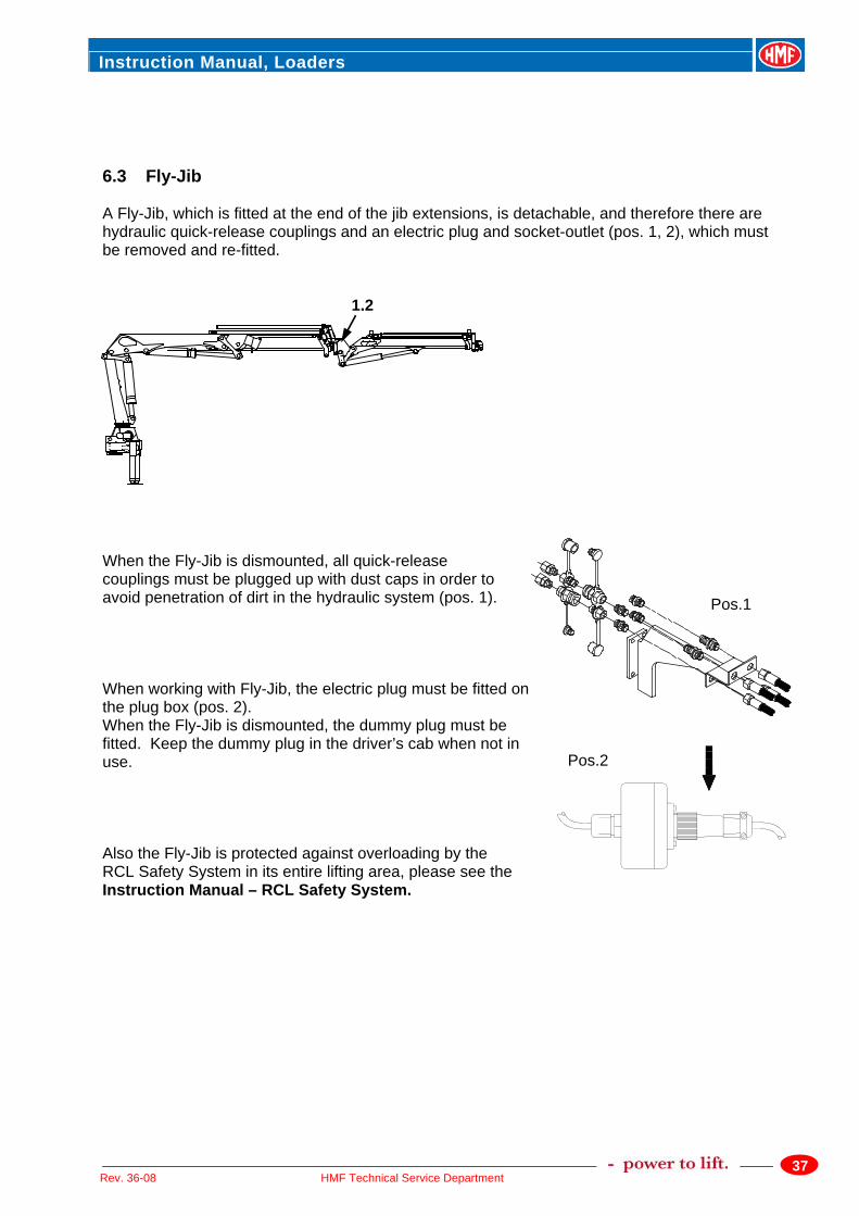
6.3 Fly-Jib A Fly-Jib, which is fitted at the end of the jib extensions, is detachable, and therefore there are hydraulic quick-release couplings and an electric plug and socket-outlet (pos. 1, 2), which must be removed and re-fitted. When the Fly-Jib is dismounted, all quick-release couplings must be plugged up with dust caps in order to avoid penetration of dirt in the hydraulic system (pos. 1). When working with Fly-Jib, the electric plug must be fitted on the plug box (pos. 2). When the Fly-Jib is dismounted, the dummy plug must be fitted. Keep the dummy plug in the driver’s cab when not in use. Also the Fly-Jib is protected against overloading by the RCL Safety System in its entire lifting area, please see the Instruction Manual – RCL Safety System.
1,2
Pos.1
Pos.2
Instruction Manual, Loaders
38HMF Technical Service Department Rev. 36-08
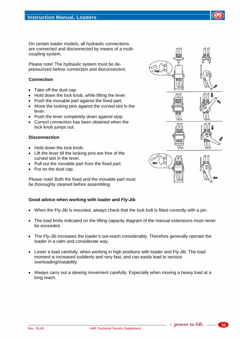
On certain loader models, all hydraulic connections are connected and disconnected by means of a multi-coupling system. Please note! The hydraulic system must be de-pressurized before connection and disconnection. Connection • Take off the dust cap. • Hold down the lock knob, while lifting the lever. • Push the movable part against the fixed part. • Move the locking pins against the curved slot in the
lever. • Push the lever completely down against stop. • Correct connection has been obtained when the
lock knob jumps out. Disconnection • Hold down the lock knob. • Lift the lever till the locking pins are free of the
curved slot in the lever. • Pull out the movable part from the fixed part. • Put on the dust cap. Please note! Both the fixed and the movable part must be thoroughly cleaned before assembling. Good advice when working with loader and Fly-Jib • When the Fly-Jib is mounted, always check that the lock bolt is fitted correctly with a pin. • The load limits indicated on the lifting capacity diagram of the manual extensions must never
be exceeded. • The Fly-Jib increases the loader’s out-reach considerably. Therefore generally operate the
loader in a calm and considerate way. • Lower a load carefully, when working in high positions with loader and Fly-Jib. The load
moment is increased suddenly and very fast, and can easily lead to serious overloading/instability.
• Always carry out a slewing movement carefully. Especially when moving a heavy load at a
long reach.

Instruction Manual, Loaders
39HMF Technical Service Department Rev. 36-08
7. Lifting Capacity and Lifting Capacity Diagrams 7.1 Lifting Capacity Labels on the Loader From the factory, the loader is equipped with lifting capacity labels for the loader as well as for the optional extras, if any (manual extensions, Fly-Jib). These labels must, just like any other labels on the loader, be intact and legible. If the label has been damaged or removed, you can get a new one from HMF. Use the part number at the bottom of the label, if any, or see the spare parts catalogue. 7.2 Lifting Capacity Diagrams As a supplement to the loader’s lifting capacity labels, the Loader Data booklet contains loads and lifting capacities of the different K-versions in standard applications, i.e. special applications and customized loaders and options are not taken into consideration. In these cases we refer to the supplementary documentation delivered and/or the lifting capacity labels on the loader. The lifting capacity limits indicated must never be exceeded.
Instruction Manual, Loaders
40HMF Technical Service Department Rev. 36-08
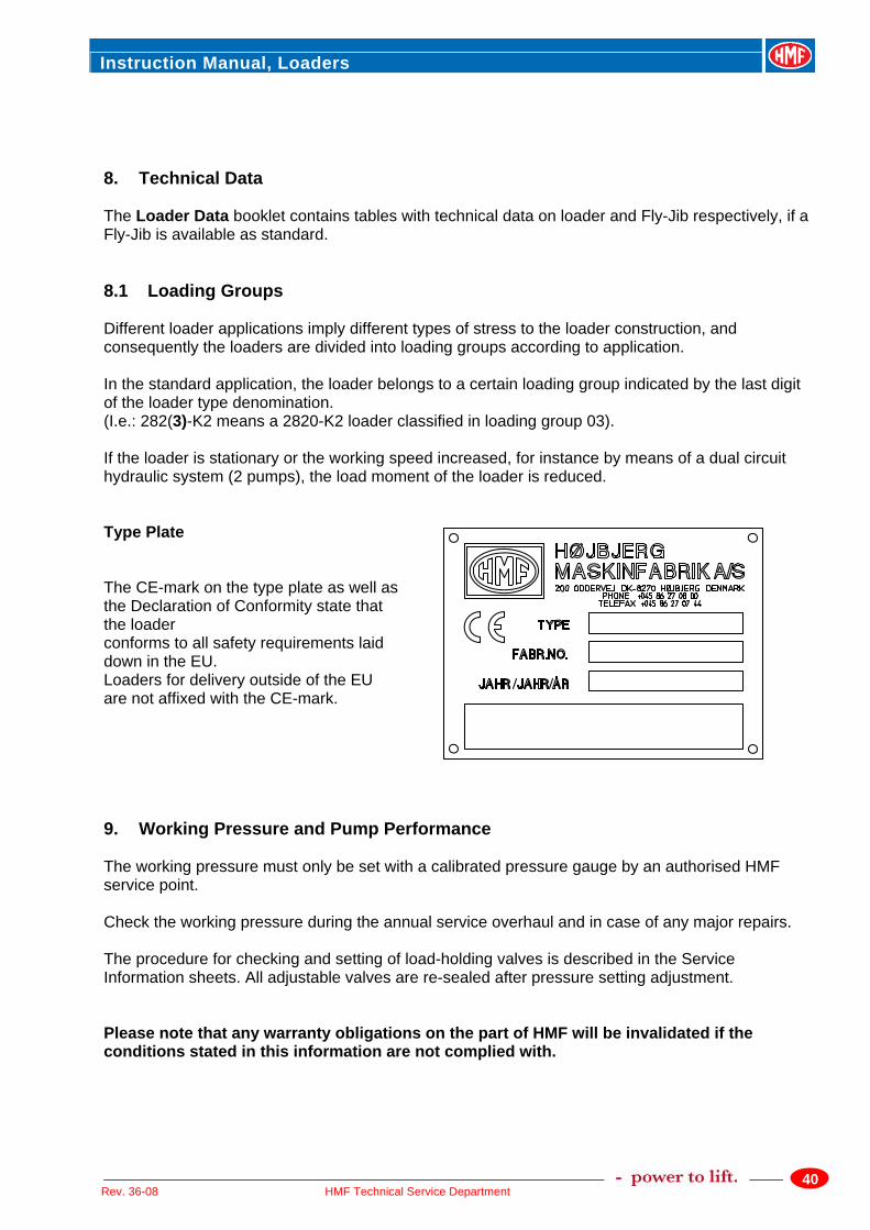
8. Technical Data The Loader Data booklet contains tables with technical data on loader and Fly-Jib respectively, if a Fly-Jib is available as standard. 8.1 Loading Groups Different loader applications imply different types of stress to the loader construction, and consequently the loaders are divided into loading groups according to application. In the standard application, the loader belongs to a certain loading group indicated by the last digit of the loader type denomination. (I.e.: 282(3)-K2 means a 2820-K2 loader classified in loading group 03). If the loader is stationary or the working speed increased, for instance by means of a dual circuit hydraulic system (2 pumps), the load moment of the loader is reduced. Type Plate The CE-mark on the type plate as well as the Declaration of Conformity state that the loader conforms to all safety requirements laid down in the EU. Loaders for delivery outside of the EU are not affixed with the CE-mark. 9. Working Pressure and Pump Performance The working pressure must only be set with a calibrated pressure gauge by an authorised HMF service point. Check the working pressure during the annual service overhaul and in case of any major repairs. The procedure for checking and setting of load-holding valves is described in the Service Information sheets. All adjustable valves are re-sealed after pressure setting adjustment. Please note that any warranty obligations on the part of HMF will be invalidated if the conditions stated in this information are not complied with.
Instruction Manual, Loaders
41HMF Technical Service Department Rev. 36-08
10. Description of the Hydraulic System The valve block of the loader is of the "sandwich" type, i.e., it is made up of a number of separate control valves; this ensures great flexibility and low maintenance costs. A main relief valve is fitted in the inlet section of the valve block to ensure that the oil pressure in the pump line does not exceed the permissible limit. This valve is adjustable and must always remain sealed. Port relief valves are mounted at the ports of the individual control valves in order to limit the pressure in the individual circuits. Normally the port relief valves will be pre-set and unadjustable. The boom, jib and extension cylinders are fitted with load holding valves with the following functions: 1. Protection of cylinders against excessive pressure 2. Checking of the lowering speed of the boom 3. Maintaining the boom in position during operations where a fixed boom position is required. 4. Locking the boom and maintaining the load in position in case of hose or pipe rupture. The stabilizer cylinders are equipped with a piloted check valve, which locks the cylinder in case of damage to the hydraulic system.
Important: The main relief valve, the load holding valves, the dump valve and the external relief valve are sealed. If these seals are broken or removed, the HMF warranty will automatically be invalidated. Therefore, it is in your own interest to have the seals checked from time to time and to make sure that they are replaced by an authorized HMF service point, should they be damaged. Any modification or alteration to the hydraulic system must be in accordance to specific agreement with HMF and such alterations should always take place at an authorized HMF service point.
Instruction Manual, Loaders
42HMF Technical Service Department Rev. 36-08
11. Load Moment Limitation The loader is equipped with a load moment limitation system (LMB). This system ensures that the permissible load moment is never exceeded, irrespective of the operator’s doings. However, it is important to keep in mind that the LMB-system does not necessarily ensure sufficient vehicle stability. Before starting to work with the loader, the operator must always make sure that the vehicle is stable in the entire slewing area of the loader. However, if the loader is equipped with an EVS-system (Electronic Vehicle Stability), the stability of the vehicle is ensured in the entire working area, because the system is constantly checking the vehicle, and immediately stopping the load moment increasing movement in case of instability, irrespective of the operator’s doings. Description of the LMB-system is in the manual: Instruction Manual - RCL Safety System. It is of great importance that the operator is familiar with the safety system! 12. Heavy Duty Lifting - HDL If the loader is equipped with a Heavy Duty Lifting (HDL) system, an increased lifting capacity is obtained, although at reduced speed. When the loader reaches its normal lifting capacity limit, the HDL-system will automatically couple in, irrespective of the operator’s doings, and the oil flow to the control valve will be reduced to approx. 20% of the normal oil flow. At the same time the loader lifting capacity is increased by approx. 10% in the entire working area of the loader. When the HDL-system couples in, the operator will be able to continue extending the load without interruption, although at reduced speed. If the load moment is reduced to the permitted load limits again, the HDL-system will increase the oil flow to normal and the working speed will increase again. However, the automatic disconnection implies that all control levers have been into neutral position at the same time as the load moment has been reduced to the permitted load limit. Please also see chapter on “Heavy Duty Lifting, HDL” in the manual: Instruction Manual - RCL Safety System.
Instruction Manual, Loaders
43HMF Technical Service Department Rev. 36-08
13. Hoses and Hydraulic Pipes The hoses must comply with the DIN 20 022 2SN standards. The pipes are manufactured in St.35.4C-NBK. 14. Bleeding of Air If for some reason air has entered into the hydraulic system, the loader is bled as follows: 1. Raise and lower each stabilizer leg twice. 2. Extend and retract the boom cylinder twice. 3. Extend and retract the jib cylinder twice with the main boom pointing downwards and twice
with the main boom pointing upwards. 4. Extend and retract the extension cylinder twice with the jib cylinder pointing almost
vertically upwards and twice with the jib cylinder pointing almost vertically downwards. 15. Repair If you discover defects, damage or leaks they should be repaired as soon as possible. Always take your repairs to an authorized HMF service point. Repairs to the hydraulic system must only be made by an authorized service point. When you order spare parts for your loader, please state: • Loader type • Loader serial number
This information can be found in this instruction manual or stamped into the metal plate on the backside of the loader column.